

Lowrance LST3800 User Manual
Pub. 988-0064-351
LST-3800
In-Dash Digital Sonar Gauge
Installation & Operation Instructions
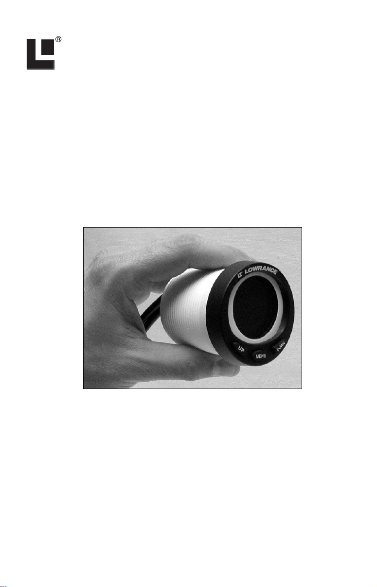
The LST-3800 is a depth and temperature gauge that comes with a 200
kHz transducer, features deep and shallow alarms and has three main
page displays. It can show depth in Meters or Feet, temperature in Fahrenheit or Celsius and its display may be set to rotate between Temperature, Depth or Dual display pages. The unit fits in a standard 2-1/8" (54
mm) hole used by most marine equipment manufacturers.
The 3800 is designed to display water depth and surface water temperature, but you MUST have a transducer with built-in temp sensor to receive temperature information.
LST-3800 temperature gauge.
Mounting Preparations
When installed, the gauge's bezel will cover a circular area at least 2-1/2"
(64 mm) wide on the front of the dash. To mount the unit, make sure
there is at least 4-1/8" (105 mm) from the front of the dash to any obstruction behind the dash. The maximum usable dash thickness is 1-1/8"
(28.5 mm). Also, make certain there is room to route the unit's cables.
The following figure shows gauge dimensions.
1
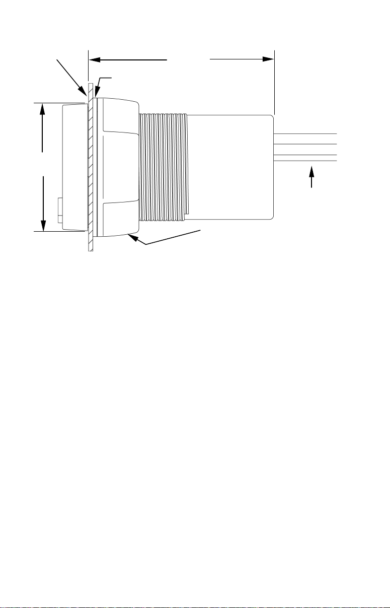
Gasket
Dash
2-1/2"
(64 mm)
Dash installation, cross-section view.
4-1/8"
(105 mm)
Cables
Threaded mounting collar
Caution:
You should read over the entire installation section before drilling
any holes in your vessel!
You can install this gauge in some other order if you prefer, but we recommend the installation sequence summarized below:
1. Determine the location for the gauge so you can plan how and where to
route the cables. This will help you make sure you have enough cable
length for the desired configuration.
2. Determine the location of your battery or other power connections,
along with the power cable route.
3. Determine the location for the alarm buzzer and its wire route.
4. If you want to turn on the gauge backlights whenever you turn on your
dashboard lights, locate your boat's dash light switch and determine how
to route the dash light wires to it.
6. Install transducer, connect power wires to the battery and route the
power/transducer cable to the gauge location.
7. Install the gauge, and connect the power/transducer cable.
8. Connect the buzzer wires and install the buzzer. If desired, connect the
dash light wires to the boat's dash light switch.
2
Recommended Tools and Supplies
Supplies are not included, unless otherwise indicated. If the dash does
not have a standard 2-1/8" (54 mm) hole, you will need a drill or saw to
make the hole. Carefully measure the dash thickness and the hole area
before cutting or drilling. The buzzer installation requires two cable ties.
If you need to extend any of the wires, use a minimum of 24-gauge wire
and wire connectors of your choice. Wire nuts or electrical tape are required to cap any unused bare wires.
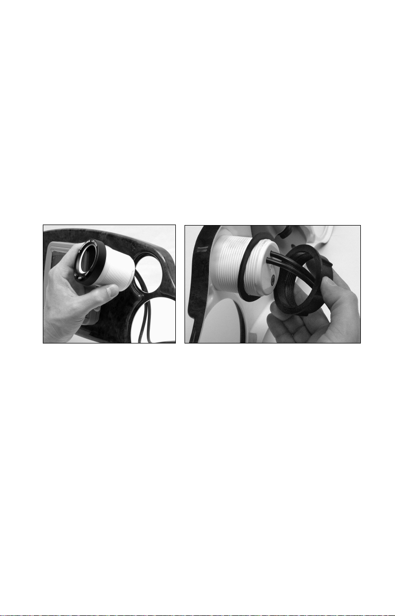
When you determine the location for the LST-3800, drill a 2-1/8" (54 mm)
hole in the dash or use an existing gauge hole. Slide the cables through
the hole from the front side of the dash, then push the LST-3800 housing
through the hole until it is flush with the dash surface. Make sure the
gauge is aligned correctly. Next, slide the rubber gasket and plasticmounting collar over the cables and onto the back side of the gauge.
Insert gauge through the hole in the front side of the dash (left). Slide
the rubber gasket over the cables, followed by the plastic collar (right).
Slide the gasket forward so it is flush with the back of the dash, then
screw on the mounting collar, turning it until it fits snugly against the
gasket and the back of the dash.
Find a buzzer location that is protected from the elements, but still will
allow you to hear the buzzer. We recommend connecting the buzzer
wires, then using two cable ties to attach the buzzer to one or both of the
cables at the back of the gauge.
Finish the installation by connecting the cables as described in the following wiring diagrams and photos.
Wiring
The LST-3800 operates from 10 to 15 volts DC (12-volt system). It must
be wired to a 1-amp fuse. Failure to use a fuse with this product
WILL VOID the warranty and could result in damage to the unit
or your boat.
3
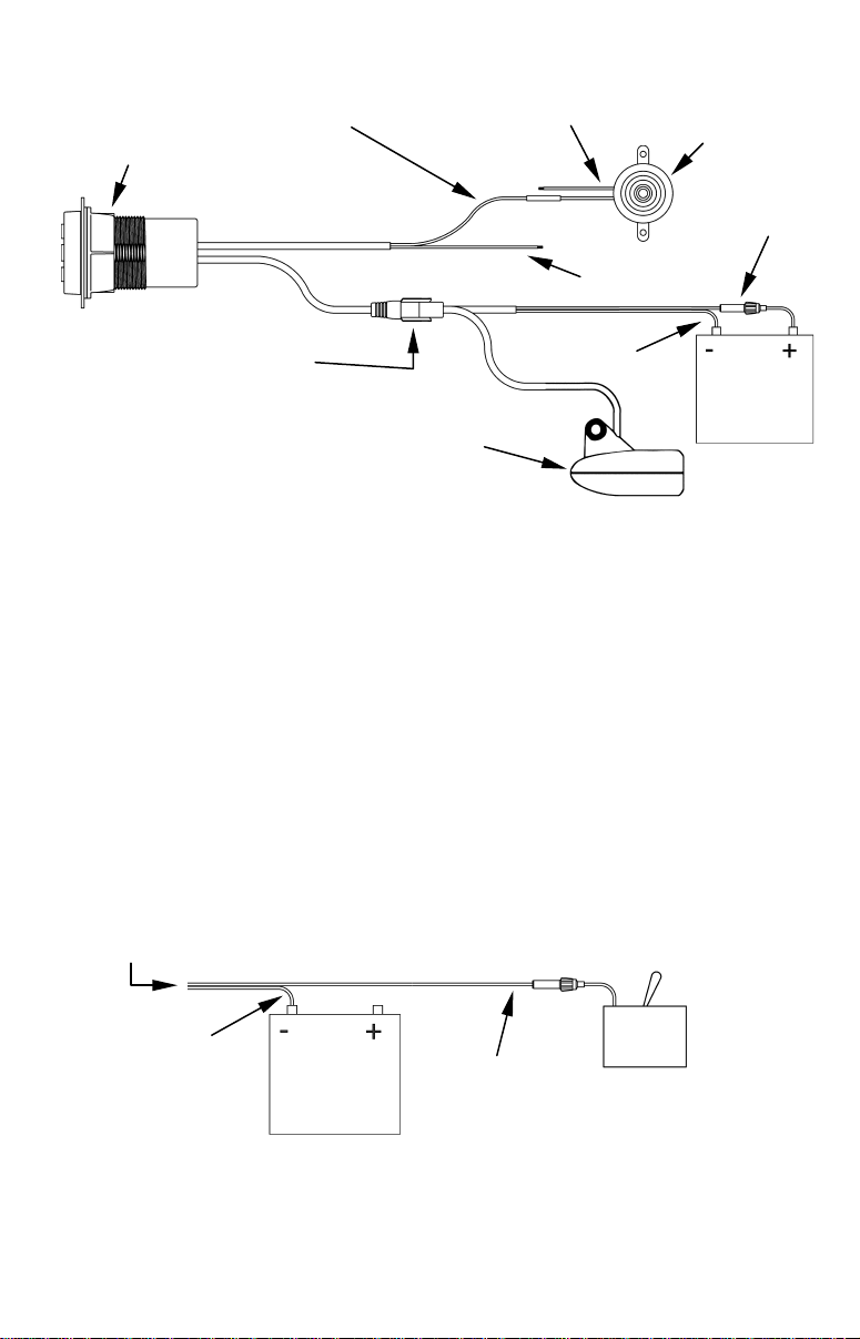
LST 3800 housing
and fuse
Power/transducer cable
Buzzer
LST black wire to
switch
wire
and fuse
buzzer black wire
Transducer
LST-3800 cable connections.
Buzzer red wire
to boat power
Red wire
Red to dash
light switch
Black
wire
12 volt
battery
In the configuration above, the unit is always on. It will draw 11 milliamps of current with the backlight off and 40 milliamps with the backlight on full brightness. Typically, the maximum recommended current
load on a boat in storage is about 50 milliamps. A battery will self discharge at a rate of about 9 milliamps. A battery's normal discharge plus
the gauge current (lights off) amounts to approximately 20 milliamps,
well below the recommended load limit in storage.
To automatically have the gauge backlights turn on when you turn on the
other dashboard lights, connect the red dash light wire to the switch controlling the dash lights.
If you want to turn off the gauge when your not using it, connect the red
wire from the power/transducer cable to your boat's accessory switch, or
install an optional switch between the unit and the power source. See the
following figure.
Power/transducer
Black
This wire configuration lets you turn off the gauge when it's not in use.
12 volt
battery
Red wire
4
Accessory
 Loading...