

Page 1

INSTALLATION AND OPERATION
MANUAL
MODEL LRG-1510C
GRAYLINE® RECORDER
Printed in U.S.A.
988-0055-08
LOWRANCE
•
12000 F. SKELLY DR.. TULSA. OKLA. 74128
ELECTRONICS,
INC.
PDF compression, OCR, web-optimization with CVISION's PdfCompressor
Page 2
NOTICE
Periodically
move
any
sensitivity
oil
or
wash
film
may
Transducer Face with
that
even
collect Oil and dirt on the face will reduce
may
prevent
the
GOT A PROBLEM? LET US HELP!
It
have a
you
before
help
Assistance can often be extended
problem
sending
one of our Authorized
Customer Service
Please detail the
ment
be able to save
may
If it is determined that
tions will be
provided.
SCHEMATIC DIAGRAM AND PARTS LIST
Should
rance TRUELINE
Electronics, Inc.,
sure and
SONAR INSTRUMENT
desire a Schematic
you
us the Model Number and Serial Number of
give
with
it in for
Department
problem you
RECORDER,
12000 East
your
repair.
Service Centers or the Lowrance
the inconvenience of
you
unit must be
your
Skelly Drive, Tulsa,
sounding.
sonar
by telephone
in
Tulsa,
are
experiencing.
Diagram
send
$1.00
and water to re-
soap
unit,
please give
us a chance to
or letter. Write or call
Electronics, Inc.,
OK.
(Toll-free 1-800-331-3889).
Our Service
returning your
returned,
and Parts list for
to PARTS
full
shipping
your
Lowrance
LIST,
Oklahoma 74128. Be
Depart-
unit.
instruc-
Low-
your
25
PDF compression, OCR, web-optimization with CVISION's PdfCompressor
Page 3
SPECIFICATIONS
Depth Ranges
Operating Frequency:
Pulse
Length: (duration
Operating Voltage:
Output
Current
Power:
Operating
Weight
Dimension:
Minimum .
Maximum.
With Gimbal Mount
Width 121/4'
Height
Depth
—
LRG-1510C
of
pulse):
0- 30 feet
0- 60 feet
0-120
feet
0-360 feet
192 kHz
second); accuracy
0.6
percent
volts DC
to 1.8
printing density
power.
900 watts
watts
(112
8.5 lb.
51/4"
(3.9 Kg)
Instrument
Width 9½"
Height
Depth
(192,000 cycles per
is within
its.
amps depending
and
output
on
typical peak-to-peak
RMS)
Only
7½"
5¼"
INDEX
What It Is .
How It Works.
What It Tells You
Installation
Operation
Scale
Sensitivity
Suppression
Paper Speed
GRAYLINE® ©
How To Read
Paper Loading
Graphs
2
3
4
6
7
7
7
8
8
9
10
13
19
20
22
23
23
24
25
1
24
Stylus Replacement
Stylus
Maintenance
Belt
Replacement
Do's and Don'ts
Trouble
Specifications
Shooting
How to Obtain Service
p
PDF compression, OCR, web-optimization with CVISION's PdfCompressor
Page 4
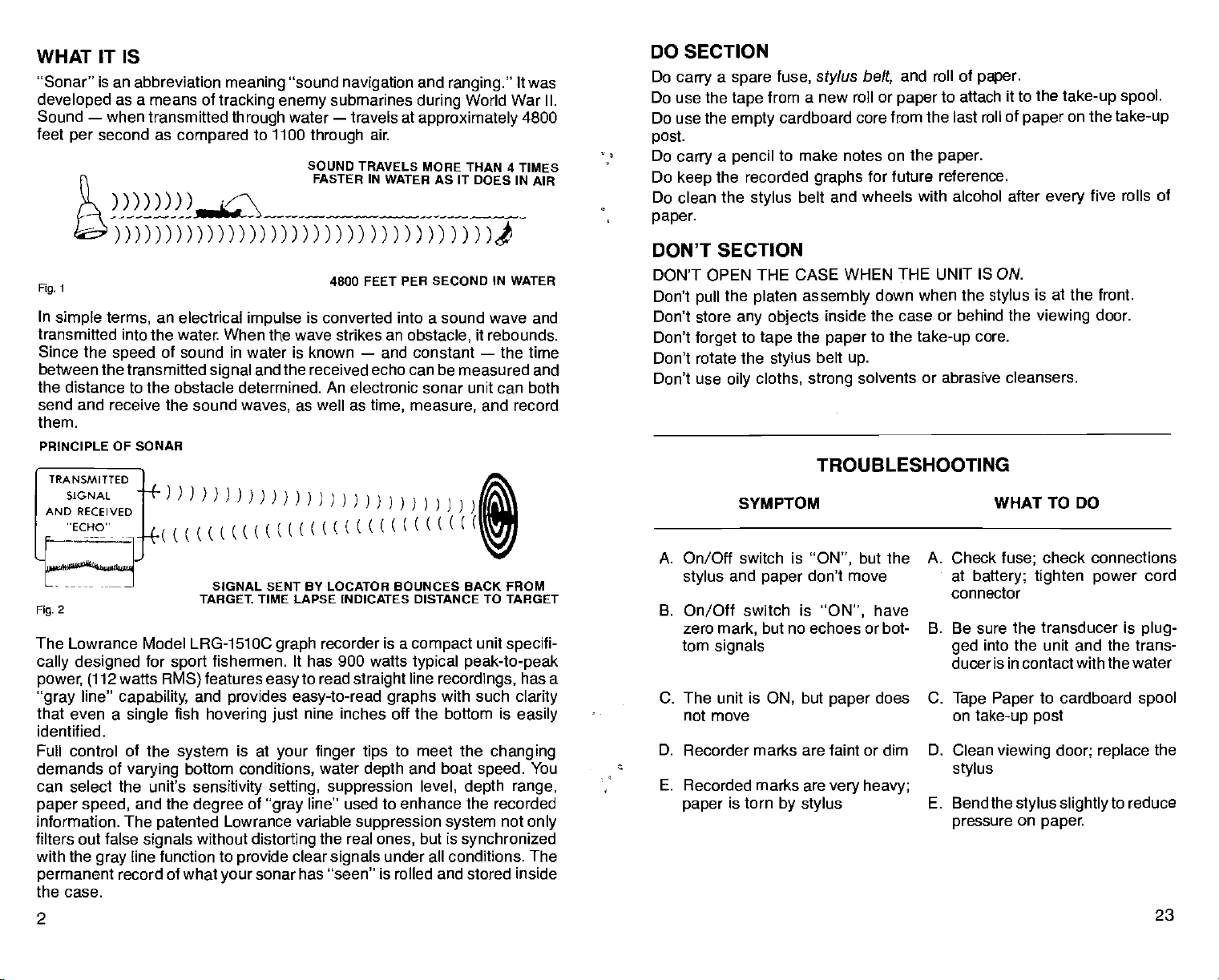
WHAT IT
Sonar" is an
developed
Sound
feet
—
when
second as
per
-
is
abbreviation
as a means of
transmitted
compared
_____
meaning
tracking enemy
through
sound
submarines
water — travels at
to 1100
through
SOUND
FASTER IN WATER AS IT
air.
and
ranging."
during
World War II.
approximately
DOES
navigation
TRAVELS MORE THAN 4
)DDDflflDDflDflfl) )flflflfl)
)I
It was
4800
TIMES
IN
AIR
DO SECTION
Do
Do use the
Do use the
post.
Do
Do
Do clean
paper.
a
carry
spare
tape
empty
carry a pencil
the recorded
keep
the
stylus
fuse,
sty!us
from a new roll or
cardboard core from
to make notes on the
graphs
and roll of
belt,
to attach
paper
the last roll of
paper.
for future reference.
belt and wheels with alcohol after
paper.
it to the
take-up spool.
on the
paper
every
five
take-up
rolls of
DON'T SECTION
4800 FEET PER SECOND IN WATER
In
simple terms,
transmitted into the water. When
Since the
between the transmitted
speed
an electrical
impulse
is converted into a sound wave and
wave strikes an
the
of sound in water is known
and the received echo can be measured and
signal
obstacle,
—
and constant
it
rebounds.
—
the time
the distance to the obstacle determined. An electronic sonar unit can both
send and receive the sound
them.
PRINCIPLE OF SONAR
TRANSMITTED
SIGNAL
ANDRECEIvED
((((((
waves,
(N
L
SIGNAL SENT BY
2
Fig.
The Lowrance Model LRG-1510C
cally designed
power, (112
line"
gray
that even a
identified.
Full control of the
demands of
for
watts
capability,
single
varying
can select the unit's
paper speed,
information. The
filters out false
with the
permanent
and the
signals
line function to
gray
record of what
TARGEt TIME
fishermen. It has 900 watts
sport
features
RMS)
and
fish
system
patented
provides
hovering
is at
bottom
conditions,
sensitivity setting, suppression
degree
Lowrance variable
without
provide
your
as well as
LAPSE INDICATES DISTANCE TO
recorder is a
graph
to read
easy
easy-to-read
nine inches off the bottom is
just
your finger tips
water
of
distorting
line" used to enhance
gray
the real
clear
sonar has "seen"
time, measure,
LOCATOR BOUNCES
straight
graphs
to meet the
depth
suppression system
ones,
signals
under all conditions. The
is rolled and stored inside
and record
I
BACK FROM
TARGET
compact
typical
line
and boat
level, depth range,
but is
unit
specif
peak-to-peak
recordings,
with
such
changing
speed.
the
recorded
not
synchronized
has a
clarity
easily
only
You
the case.
2
DON'T OPEN THE CASE WHEN THE UNIT
Don't
Don't store
Don't
Don't rotate the
Don't use
the
pull
forget
oily
platen assembly
any objects
to
tape
stylus
cloths,
inside
the
paper
belt
strong
down when the
the case or behind the
to the
take-up
up.
solvents or abrasive cleansers.
TROUBLESHOOTING
SYMPTOM WHAT TO DO
A.
On/Off
stylus
B.
On/Off
i-
zero
tom
C. The unit is
switch is
and
switch is
mark,
signals
"ON",
but the
have
paper
"ON",
don't move
but no echoes or bot-
ON,
but
paper
does
not move
D. Recorder marks are faint or dim D, Clean
E.
Recordedmarksareveryheavy;
is torn
paper
by stylus
A. Check
B. Be sure the transducer is
C.
E. Bend the
IS ON.
at the front,
is
stylus
viewing
core.
check connections
fuse;
at
battery; tighten power
connector
into the unit and the trans-
ged
door.
cord
plug-
duceris in contact with the water
Tape Paper
on
take-up post
stylus
to cardboard
viewing door; replace
stylus slightly
pressure
on
paper.
spoo1
the
to reduce
23
PDF compression, OCR, web-optimization with CVISION's PdfCompressor
Page 5
MAINTENANCE
NOTE: The
platen assembly
the
platen
to remove
Black carbon dust is created
oil-free
pressure compressed
from
After
should be
carbon dust.
stylus may
is
when
changing
stylus.
to clean the
rag
moving parts/f
five rolls of
every
wiped
Strong
All mechanical connections
haven't
DO NOT
DO NOT wash the unit
remove salt
HIGH VOLTAGE is
attempt
electronic section.
Corrosion
splices,
checked
The face of the
periodically
oily
worked loose.
any type
appy
accumulations, dust,
should be made
occur
may
or at the
periodically
transducer,
with mild
film. This is essential to have
the water.
Periodically,
cloth
page
the rubber roller
dampened
16,
Figure 29).
with
be
damaged
down.
pulled
the
viewing
air
may
the air is
paper,
clean with a soft
solvents or abrasive cleaners should not be used.
should be checked
of lubricant to the motors or
with
running
present
in the transmittersection when the unit is ON. No
by any
at the
power plug,
battery
connections.
cleaned as
and
if mounted on the transom should be washed
water to remove
soapy
alcohol,
it
if
is
A/ways
paper
during
move the
rolls. Rememberto
the
door and metal
in front of the
to the back side
stylus
move the belt down
recording process.
platen
behind the
platen
Use a
when the
paper.
be used to blow dust out of the case and
and free of oil.
dry
the
or road
unauthorized
belt and the wheels
stylus
moistened with
rag
water.
grime
in the fuse holder or
periodically
Wiping
is all that's
person
alcohol to remove
gear
it with a
to
modify
it rides on
to be sure
trains.
cloth to
damp
necessary.
or
repairthe
power
All electrical connections should be
with 400
accumulated road
any
grit sandpaper.
grime
drive should be cleaned with a
good
on the
to
improve
necessary
contact between the transducer and
paper
the friction on the drive shaft.
of
soft,
Low
away
they
cord
or
(See
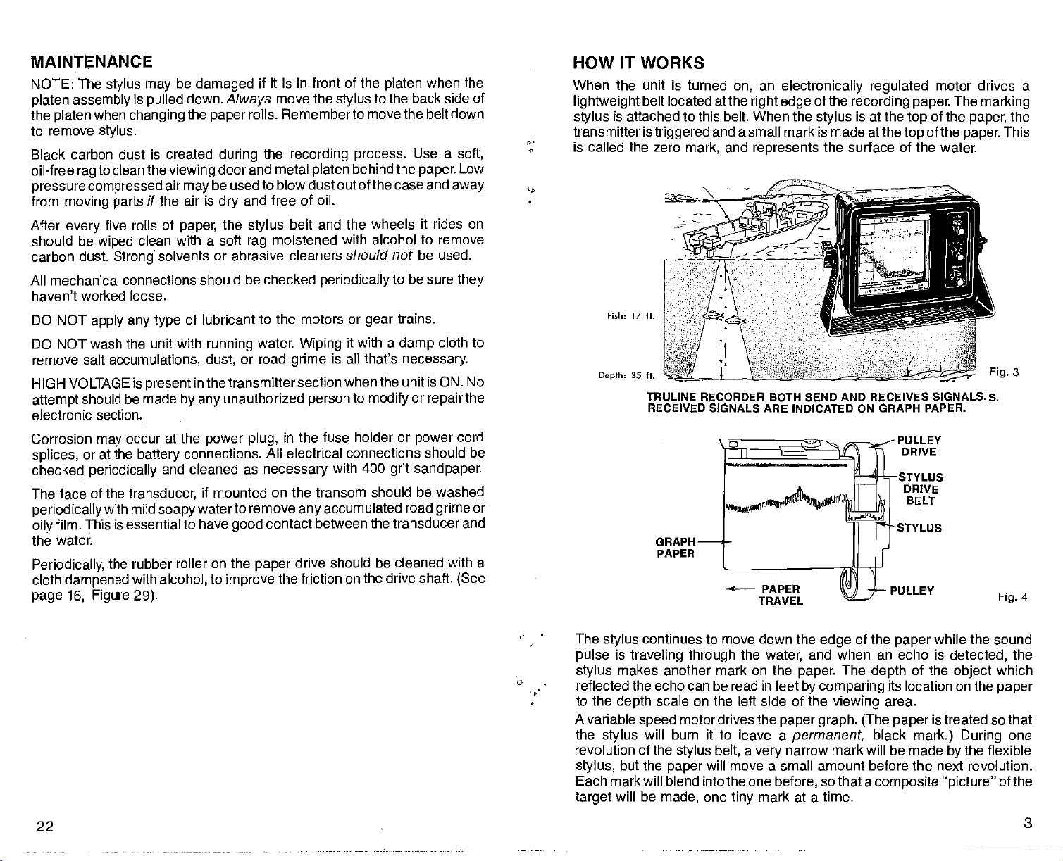
HOW IT WORKS
When the unit is turned
lightweight
stylus
transmitter is
is called the zero
Depth: 35 ft.
belt located atthe
is attached to this belt. When the
triggered
Fieh: 17 ft.
TRULINE RECORDER BOTH SEND AND RECEIVES SIGNALS. S.
RECEIVED SIGNALS ARE INDICATED ON GRAPH PAPER.
and a small mark is made at the
and
mark,
—
an
on,
right edge
represents
PAPER
TRAVEL
electronically regulated
of the
recording paper.
is at the
stylus
top
top
the surface of the water.
DRIVE
BELT
STYLUS
PULLEY
motor drives a
The
of the
of the
marking
paper,
paper.
Fig.
This
Fig.
the
3
4
The
pulse
C
• ;
stylus
reflected the echo can be read in feet
to the
A variable
the
revolution of the
stylus,
Each mark will blend into the one
target
22
PDF compression, OCR, web-optimization with CVISION's PdfCompressor
continues to move down the
stylus
is
traveling through
makes another mark on the
scale on the left side of the
depth
motor drives the
speed
will burn it to leave a
stylus
but the
will be
stylus
paper
made,
the
a
belt,
will move a small amount before the next revolution.
one
very
tiny
of the
edge
and when an echo is
water,
The
paper.
depth
by comparing
viewing
paper graph. (The paper
permanent,
black
narrow mark will be made
before,
mark at a time.
so that a
composite "picture"
while the
paper
detected,
the
of
its location on the
area.
object
is treated so that
mark.) During
the flexible
by
sound
the
which
paper
one
of the
Page 6

WHAT IT TELLS YOU
Small boat sonar
examine bottom
LRG-1S1OC
bottom are
game
contours,
be shown
identified
characteristic 'arched"
roundings — layers
under
shown.
0—
—
10
—
20
—
30
given
—
fish
submerged shipwrecks
separately
—
conditions,
good
systems
contours,
far
goes
beyond
—
schools of bait fish are
there is a continuous
—
concentrations of
at
trolling speeds
signature
of water with different
and vertical movement of
are
routinely
and locate
the
ordinary.
used to measure water
fish — but the
easily
display
—
fish as close
individual fish are
which
algae,
distinguishes
Clues to the
distinguished
of
information about bottom
together
moss or
commonly
temperatures
fish, (up
capability
composition
as six inches will
plankton
recorded with a
them
from their sur-
can be detected
or
down),
from
depth,
of the
of the
solitary
can be
can be
1
60
38
5
Fig.
LOWRANCE
This is a
sample
A and 0 indicate
represents
bottom surface which
surface,
time for a sonar
doubled. If the true bottom
If the true
indicate
baitfish scattered from 4 feet to 20 feet. It is
medium size fish
of the
return to the bottom and reflect back to the receiver
large
paper graph (H)
STRAIGHT LINE RECORDER
of the
graph printout by
bottom
an echo
signal
were ten
depth
fish. The thermocline is indicated at 28 feet
by
depths
second
(a
causes the sonar
signal)
to travel to the
reading
then the echo would occur 20 feet. C and F
feet,
their arched"
indicates "zero" or the water's surface.
a Lowrance
of 16 feet and 46 feet
caused from a
signal
bottom and back to the surface has
is 16
feet,
signatures.
Straight
Line Recorder.
respectively.
hard or reflective
very
to bounce back to the water's
Therefore,
the
also
will
echo
possible
appear
(G)
to see small and
The dark line
at 32 feet.
with schools of
across the
B
the
top
4.
5. Position the new belt on
6. Close
the belt at the
Grasp
move it
other
forefinger. (See Figure 38.)
gently
to the left while
stylus
the wheels
remove the old one. BE SURE the
UP.
the front of the case. Latch
holder with the thumb and
pushing
the belt off the
by reversing
fingers
both catches on the
the
of the new
Fig.
forefinger
wheels with the
procedure
stylus
top
used to
are
pointed
of the
and
unit.
PDF compression, OCR, web-optimization with CVISION's PdfCompressor
Page 7

Fig.
Fig.
35
37
The 30' scale
samples
therefore, increasing
.r' "
p'7
gives you
below).
BOTTOM
a new dimension in resolution
The LRG-1S100 does this without
life of
stylus
-Is
THIS IS WHAT A REPRESENTATIVE
and detail.
increasing
belt,
stylus, bearings
AREA WOULD LOOK LIKE ON THE 0-30' SCALE.
motor
and the motor itself.
(See
speed,
chart
Fig.
—
10'
—
25'
'—30'
6
5'
p
7. After
installing,
Figure 37)
against
the left
the stainless
leg
8. Close the front of
STYLUS BELT
High voltage
TURN THE UNIT OFF.
1.
2. Release both
the case front to
of
3. The
20
PDF compression, OCR, web-optimization with CVISION's PdfCompressor
stylus
platen assembly.
DOWN to
if the
bend the
down more
the case. Latch both catches on the
REPLACEMENT
is
present
catches on
expose
belt rides over two wheels located at the
Refer to
position
the
won't
stylus
right leg
steel
plate.
(but
—
down so that more
not so far that it
CAUTION
all the
print
way
If it still does not
digs
—
down the
pressure
all the
print
into the
top
paper, (See
is exerted
way,
paper).
of the case.
in the electronic section when the unit is
turned on.
thetop
stylus
of the case. Pull out and down on the
the
Figure
at the center of
stylus
4 on
belt.
page
3. Move
the
platen.
right edge
the front of the belt
bend
top
of the
occasional
We
pro.
from
THIS IS WHAT THE SAME AREA
0-60' SCALE.
fisherman,
encourage you
investment and to boost
your
BE SURE to insert the two rubber
on
gimbal
diameter)
gimbal
between
ment
friction to hold the unit at
bracket. The
of
grommet goes
bracket so that it is sandwiched
gimbal
(see drawings).
The LRG-1510C isa
complete
and flexible
to
bracket and sonar
The
sonar. Its controls
enough
the remainder of
study
UPPER
(SEE
side
larger
inside of
on
grommets
the desired
your boating
CHART)
grommets
(larger
instru-
provide
angle.
are
simple enough
to
satisfy
the most
this booklet to
and
fishing pleasure.
WOULD LOOK
____________________
for the
demanding
the most
get
7
Fig.
—
LIKE ON THE
0'
5
Page 8

INSTALLATION
MOUNTING
convenient area is suitable for
Any
for the best
gimbal
bracket for wood screws or thru-bolts. If
viewing angle.
There are
stiffener can be used on the back side of thin
If
the desired
mounting
trial run should be
readings
are not affected.
location is closer than 18" to a
with the unit/n
made,
POWER CONNECTIONS
12 volt DC
electrical
but if
ous
the
If a
any
crimp-type
power
plastic
system.
have
you
flashes on the
battery.
longer power
hardware store.
connections which can cause
electrical
for the
power
Power
problems
dial)
cable is
connectors.
Splices
tape.
depth
may
with electrical interference
it can be minimized
required,
Simple twisting
mounting, providing
eight mounting
operation,
sounder is
be
picked up
supplied
at an
by connecting power directly
use
should be soldered. If this can't be
ordinary
of
splices may
interference.
the unit can be tilted
holes in the base of the
necessary,
fiberglass panels.
magnetic compass,
a wooden
to be sure the
from the boat's 12 volt
accessory
(indicated by
#18
lamp
or
power buss,
cord available at
done,
result in intermittent
all
Tape
splices
a
compass
extrane-
to
use
with
STYLUS REPLACEMENT
—
High voltage
1. TURN THE UNIT OFF.
is
present
2. Release both catches on the
of the case front to
3. The
platen
at
the center of the
belt rides over two wheels located at the
stylus
assembly.
in
the electronic section when the unit is
expose
Move the front of the belt DOWN to
platen.
CAUTION
turned on.
of the case. Pull
top
the
stylus
belt.
—
and
out
(See Figure 34.)
down on the
right edge
position
the
top
of the
stylus
IMPORTANT
When
installing
with the unit is attached to the center
to the
power
cable in case either is ever shorted. A
fuse to the
8
Fig.
The
positive
unit is
protected
result if
NOTICE
the
source as
cable.
power
conducter in the
from accidental
battery
connections are
power cable,
possible.
Ground
(Negative)
power
make certain that the in-line fuse
conductor of the
This will
protect
connector is
(Positive)
both the unit and the
supplied
power
cable as close
to attach the
cable is the center conductor. The
polarity
wrong. (However,
reversals and no
the unit will
damage
not
supplied
power
will
work)
34
Fig.
4.
Hold the
by starting
holder.
stylus
5. Before
it to
Figure
6. Refer to
the tabs on
the
stylus away
belt
stylus
at its left
installing
35.
Figure
stationary
and
edge
the new
stylus,
36 to be sure the
the holder. Be sure it moves
from the
edge
with
one
finger,
moving
it out
be sure it is bent
new
stylus
freely
it
is
rubbing
and remove the old
from under the tabs on the
properly by comparing
is
positioned correctly
in the two slots. If
on until it does move
not,
stylus
under
bend
freely.
19
PDF compression, OCR, web-optimization with CVISION's PdfCompressor
Page 9

10. Push the
engages
11.
Close the front
Latch both catches on the
I
platen assembly
the catch inside the
of the case.
back to its
of the case.
top
of the case.
top
fl---
operating position.
(See Figure 32.)
C---
(See
Figure 33.)
Turn the unit on.
12.
Move the Chart
Speed
clockwise. Watch
the
paper long
enough
sure it is
smoothly
evenly
platen.
flutters or
paper
begins
up-hill', repeat
8.
Step
Be sure it
32
Fig.
knob
fully
to be
moving
and
across the
If the
to run
OPERATION
—
SCALE KNOB
select
recording depth.
are four
ON/OFF
positions:
AND SENSITIVITY KNOB
to turn the uniton. The
a
knob. When
information is
over
have
When
This is normal and is caused
of the
When detailed information about brush
dine is
to the illustration below to see what effect the
recorded information.
that
radio,
soft,
muddy
to be
higher.
high Sensitivity settings
water,
desired,
used to
weaker
is,
cruising,
desired,
bottoms,
making
the
Sensitivity
There
30 feet
60 feet
120 feet
360 feet
9
Fig.
—
Rotate the On/Off knob clockwise
Sensivity
signals
knob works much likethe
will be detected with
or at other times when
the
Sensitivity setting
(which produce
are
bythe returning signal reflecting
a second
trip
knob should be set at about 3/4
a second bottom
used,
to the bottom and back.
piles,
volume
higher settings
just simple
bottom-contour
can be low. In
weak
echoes),
echo will
individual fish or
Sensitivity setting
control
of the
water or
deep
the
setting
off the surface
the
point.
has on the
will
appear
thermo-
Refer
on
33
Fig.
PDF compression, OCR, web-optimization with CVISION's PdfCompressor
Page 10

.t!!_!Tflr7%1T.WV_
SENSITIVITY:
ONLY
THE BOTTOM SIGNAL
IS
DISPLAYED. ALL FISH
SIGNALS ARE LOST.
/4 SETTING
Fig.
"1
10
4-
SENSITIVITY: ¾ SETTING
A.
B. THERMOCLINE
C. BAITFISH
D.
-
I—
TREE
GAME FISH
ARCHED SIGNATURES DUE TO
VERY SLOW BOAT
SCHOOL
(NOTE:
ELONGATED
SPEED)
Fig.
ii
8. Draw the end
friction
core.
housing.)
roller,
(See Figure 30.) (Hint:
of the
over the
across the face of the
paper
take-up core,
small
and
strips
it
tape
of
tape may
platen,
squarely
be stored inside
around the
to the
take-up
Fig.
30
Recording
complished
higher.
information about this
SUPPRESSION KNOB — Is used to reduce interference
Noise,
electrical
disturbed
could
Fortunately,
signals. Advancing
these
This
pression
separate
page
Advance the knob
unwanted noise marks. Most of the time at low or
suppression
PAPER SPEED KNOB — Controls the
detail when
the
paper speed
maximum. This will show
speed
When
individual fish with an arched"
at
trolling speed
Refer to the section Arched
in
electronic
source,
terms,
(such
with the
important
is
any
as the
engine's ignition system),
Sensitivity
Signatures,"
function of
undesired
water which is called cavitation noise. In both
produce
unwanted,
patented design
unwanted marks on the
noise
pulses
short
are
the
Suppression
pulses
is exclusive with Lowrance.
settings,
the
graph
paper. (See page 11, Figure
relatively
short in time
knob will cause the
without
record becomes coarse and the
reducing
fish from the bottom or from other fish
12,
Figure 22.)
Therefore,
selling only
the lower the
as far as
necessary
suppression selling
will be needed.
trolling
and
knob
information from
charting
on the 360' scale in
looking
up
for
at least
proper
being compressed. (See
speed
or when
fish,
half-way.
fish arches at low
water,
deep
signature
your
signal.
the
of the chart
running
For best
the
can
knob at the
on
recorder,
It
compared
sensitivity
However,
will
usually
3/4
page
can be caused
or
air
by
cases,
system
with
be decreased.
to remove the
trolling speeds,
paper.
at
high speed,
detail,
speeds
'How to Read
paper speed
turn it
and
be ac-
or
point,
10
for more
from noise.
an
by
bubbles in
the noise
to real sonar
18.)
to
reject
in
any way.
high sup-
to
ability
(See
the better.
erratic,
no
For
good
turn
to
up
keeps high
Graphs.")
should be
9. Hold the
amount of tension on the
(See Figure 31.)
take-up spool,
and turn the
It should be
paper.
supply spool
snug against
clockwise to
put
the
a small
platen.
31
Fig.
17
PDF compression, OCR, web-optimization with CVISION's PdfCompressor
Page 11

6.
Remoove
Align
(See Fig. 28)
into
NOTE: Both
However,
take-up
notches should be
LPG-603 chart
when
sary
LPG-602
the
empty supply
core from the
the two notches in the core with the tabs on the
Push
the
paper
place.
LPG-602 and LPG-603 chart
to use
side of the chart
the
1/4"
comes with the notches so no modification is neces-
paper
the
using
paper
and LPG-603 chart
core from the LPG-602 chart
paper
drive,
wide
core on the
paper
chart drive without modification.
Side ifl the same manner.
right
lowertake-up spool.
retainer knob in and rotate it until it locks
can be used in this unit.
paper
notches must be cut into the core. These
3/16"
by
take-up
can be used on the
on both sides of the core.
deep
side of the
paper
supply
on the
paper
drive. Both
side of the
turned down to no more than
between
stylus
strikes,
the
half-way
paper
also be turned down to conserve
cerned with fine detail.
r
p.'
for the best record. If
is
running
paper
too fast. The
when not
gaps appear
paper speed may
looking
for fish or con-
,/'
•
b
L. -
BOULDERS/LARGE ROCKS
GRAYLINE OFF"
Fig.
12
BOULDERS/LARGE ROCKS Ag. 13
GRAYLINP:
"ON"
r:
I
I'-..'
7. Put a fresh roll of
spool
paper
end
must
caps
spool
on the
paper
in
position
supply
side
on the
(right)
off the bottom of the roll.
w
centering posts
of the
platen assembly.
(See Figure 21.)
of the
paper
The
r is.
GRAYLINE®: 'OFF'
A. FISH
B. TREES
C. FISH IN TREES
D. BAIT FISH SCHOOL
GRAYLINE®
',,-,
-
outline the
and
brush;
bottom returns
Hg.
29
Arrow indicates friction roller
or
weedy
gray
etc. In
control
bottom
line. Do not
water less
knob.
PDF compression, OCR, web-optimization with CVISION's PdfCompressor
/'
—C
14
Fig.
ON/OFF KNOB
bottom contour which
it can
also
a
give
very Strong signal
returns a weaker
advance the
than
30',
—
clues
control too far or it
click
just
GRAVLINP: "ON"
A. FISH
B.
TREES
C. FISH IN TREES
D. BAIT FISH SCHOOL
The
GRAYLINE® function
otherwise
might
to the
composition
a
causing
signal
wide
which is
emphasized
will
the knob "on"
be hidden
of the
line. A
gray
line on
gray
—
do not
can be used to
beneath
bottom. A hard
with a narrow
advance the
soft,
fish,
trees
muddy
trees,
Page 12

HOW TO READ GRAPHS
"ARCHED
is that
separates
shown below. The distance to
a fish when
sound is shown as
the
fish
SIGNATURES"
it can record individual fish with a characteristic arched mark that
them from their
it
moves into the sonar's cone of
'A" in
has moved to the center of the
the distance to it will be
and as
will increase
it moves out of the
as shown in line "C".
again
—
stationary
the
drawing.
shorter, (line "B"),
cone,
A remarkable
surroundings.
When
cone,
the distance
advantage
The reason for this is
of the LRG-15100
5. To remove the full
knob until it
removed from the
snaps
take-up
roll,
out.
(See Figure 26.)
paper spool
in and rotate the left
push
The roll can now be
end
caps. (See Figure 27.)
paper
retainer
easily
If a
partial
time on
but does not curve back
up
is because the transducer is not
aimed
Sharp,
knob is set at the 3/4
arch occurs most of the
unit
your
straight
well-defined
down.
mark curves
(the
signatures
point
down),
it
16
Fig.
will occur most often when the
or
higher. (See (C), Figure 17.)
Remember, too,
that there must be some movement between the fish and boat to
the arched mark.
17
Fig.
0—
—
20
—
30
—
40
—
50
—
60
THERMOCLINES — The
constant
junction
from
of a warm and cool
to bottom.
top
temperature
Layers
of water is called a thermocline. The
layer
and thickness of the thermocline can
lakes there
deep
important
Many
suspend just
to the fisherman because
times bait fish will be above the thermocline while
below it.
be two or
may
(See (G), Figure 17.)
more,
Your Lowrance Model LRG-1510C can detect this invisible
but the
higher.
Sensitivity
knob will
probably
of water in the lake is seldom
of
different
vary
at different
they
have to be set at the 3/4
temperatures form,
with the season or time of
depths.
are areas which fish are active.
Thermoclines are
larger game
layer
in the
Sensitivity
develop
and the
depth
In
day.
fish
water,
or
point,
1
Fig.
27
15
PDF compression, OCR, web-optimization with CVISION's PdfCompressor
Page 13

3. Move the
position
the belt
the
up
belt
stylus
marking stylus
—
the
stylus may
SPECIAL NOTE: The
down unless the
pulled
stylus
4. Pull out and down on
expose
25
Fig.
the
paper spools. (See Figure 25.)
DOWN,
(on
the
on the back side of the
be
damaged.
stylus may
be
damaged
right
side
of the
platen.
if the
has been moved to the back side of the
the tab at the
center of the
top,
viewing area),
NEVER move
platen assembly
platen.
platen assembly
to
is
to
High Speed (46 M.P.H.)
SUPPRESSION: OFF
SENSITIVITY: ON
NOTE POOR RECORD CAUSED
—
1/2 POSITION
BY NOT USING SUPPRESSION
WHEN AT HIGH SPEED.
18
Fig.
High Speed (46 M.P.H.)
SUPPRESSION: ON
SENSITIVITY:
ON
—
ADEQUATE SETTING
—
POSITION
1/2
I .
flg.1g
A. JIGGING A 1¾ oz. HOPKINS
'SPOON IN SUBMERGED TREE.
B. FISH SIGNALS
VERY SLOWLY
C. BAIT FISH
(BOAT
OVER
DRIFTING
FISH).
'1
SCALE: 0 TO 60 FEET
SPEED: SLOW
PAPER
SUPPRESSION: OFF
DEPTHS: RECORDED FROM
INCHES TO 7'/2 FEET
.:y ...:wfl®
M¼&VM I
18
IA
20
Fig.
GRAYLINE®: 'OFF"
A. FISH
14
PDF compression, OCR, web-optimization with CVISION's PdfCompressor
ON OR NEAR BOTTOM
GRAYLINE®:
A. FISH ON OR NEAR BOTTOM
"ON"
Page 14

tr\
____
-.
PAPER LOADING
—
CAUTION
1
High voltage
is
present
in the electronic section when the unit is
turned on.
—
/\t'
"N\2_
—
-
-
P
21
Fig.
A. FISH
B. JIGGING A
SUPPRESSIONz TOO HIGH SUPPRESSION: PROPER SElliNG
(NOTE
SCHOOLS OF BAIT FISH ARE ELON- SCHOOLS OF BAIT
GATED AND RUN
BOTTOM.)
DRIFTING UNDER BOAT.
FISH
MOVED FROM 13½ FEET
TO 21
FEET TO 12 FEET WHILE
DRIFTING/SWIMMING WITHIN
THE
CONE OF SOUND.
OFF 8011DM.
SCALE: 0 TO60 FEET
GRAYLINE! "ON"
THAT RECORDER SIGNALS FROM
LEAD-HEAD LURE
TOGETHER WITH THE
A. A
FISH SUSPENDED UNDER BOAT
B. FISH SWIMMING UP TOWARDS BOAT
C. SCHOOL OF BAIT FISH
D. SURFACE CLUTTER
SCALE: 0 TO 60 FEET
GRAYLINE®: "OFF"
Fig.22
DISTINCT INDIVIDUAL
(NOTE
FISH.)
1. TURN THE UNIT
2.
Release both catches on the
of the case front to
C
C
OFF
expose
I
of the case. Pull out and down on the
top
the
platen assembly. (See Figure 24.)
Fig.
top
23
.1
1
END-OF-PAPER MARKER
has a red line
2 to 3
feet before the end of
printed
at the bottom of
—
The
the
paper (See
graph paper
the
paper
to
Figure
used in the LRG-1510C
when there is
signify
23 on
Page 13.)
only
/
24
Fig.
PDF compression, OCR, web-optimization with CVISION's PdfCompressor
13
 Loading...