

Page 1
www.lowrance.com
Pub. 988-0105-971
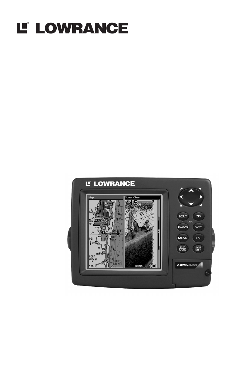
LMS-320, LMS-320DF
Fish-finding Sonar & Mapping GPS
Operation Instructions
Page 2

Copyright © 2002 Lowrance Electronics, Inc.
All rights reserved.
Lowrance
®
is a registered trademark of Lowrance Electronics, Inc.
MapCreate is a trademark of Lowrance Electronics, Inc.
Marine-Tex is a trademark of Illinois Tool Works Inc.
Navionics
is a registered trademark of Navionics, Inc.
Points of Interest Data in this unit are by infoUSA,
copyright 2001-2002, All Rights Reserved. infoUSA is a
trademark of infoUSA, Inc.
eXitSource Database, copyright 2001-2002 Zenrin Co.
Ltd. Exit Authority and eXitSource are trademarks of
Zenrin Co. Ltd.
Lowrance Electronics may find it necessary to change or end our
policies, regulations and special offers at any time. We reserve the right
to do so without notice. All features and specifications subject to change
without notice. All screens in this manual are simulated. On the cover:
LMS-320 shown. Other models covered in the manual are similar.
For free owner's manuals and other information,
visit our web site:
www.lowrance.com
Lowrance Electronics Inc.
12000 E. Skelly Dr.
Tulsa, OK USA 74128-2486
Printed in USA.
Page 3

Table of Contents
Sec. 1: Read Me First! ...............................................................1
Capabilities and Specifications: LMS-320 and LMS-320DF ........ 3
How LMS-320 Sonar Works ......................................................... 5
How LMS-320 GPS Works ........................................................... 6
Introduction to GPS and WAAS................................................... 8
How to Use this Manual: Typographical Conventions.............. 10
Sec. 2: Installation & Accessories ........................................ 13
Preparations................................................................................ 13
Transducer Installation.............................................................. 13
Recommended Tools and Supplies ......................................... 14
Selecting a Transducer Location............................................ 14
Transom Transducer Assembly and Mounting .....................16
Trolling Motor Bracket Installation....................................... 22
Transducer Orientation and Fish Arches .............................. 23
Shoot-Thru-Hull Preparation................................................. 23
Shoot-Thru-Hull Installation ................................................. 25
Sensor Chart ............................................................................... 27
Optional Speed Sensor Installation ....................................... 28
GPS Antenna/Receiver Module .................................................. 29
Power Connections...................................................................... 30
NMEA/DGPS Cable Connections............................................... 31
Mounting the Unit: Bracket, in-Dash or Portable .................... 33
Bracket Installation................................................................ 34
in-Dash Installation................................................................ 36
Portable Installation............................................................... 36
MMC or SDC Memory Card Installation................................... 37
Other Accessories........................................................................ 38
Sec. 3: Basic Sonar Operation............................................... 41
Keyboard .....................................................................................41
Power/Lights on and Off............................................................. 42
Main Menu .................................................................................. 42
Pages ........................................................................................... 44
Satellite Status Page .............................................................. 44
Navigation Page...................................................................... 45
Map Page................................................................................. 45
Sonar Page .............................................................................. 46
LMS-320 Series Sonar Quick Reference.................................... 49
Sonar Operations ........................................................................ 50
Fish Symbols vs. Full Sonar Chart ........................................ 52
Other Free Training Aids ....................................................... 53
Sec. 4: Sonar Options & Other Features ............................55
ASP (Advanced Signal Processing) ......................................... 55
i
Page 4

Alarms ......................................................................................... 56
Depth Alarms .......................................................................... 56
Zone Alarm .............................................................................. 57
Fish Alarm............................................................................... 58
Calibrate Speed........................................................................... 58
Chart Speed................................................................................. 59
Depth Cursor............................................................................... 60
Depth Range - Automatic ........................................................... 60
Depth Range - Manual................................................................ 61
Depth Range - Upper and Lower Limits ................................... 61
FasTrack .................................................................................. 63
Fish I.D. (Fish Symbols & Depths) ......................................... 63
FishTrack ................................................................................. 65
FishReveal ............................................................................... 66
Frequency (Change Transducer Frequency) .............................68
Grayline
..................................................................................... 69
HyperScroll .............................................................................. 71
Log Sonar Chart Data ................................................................ 71
Noise Rejection............................................................................ 71
Overlay Data ............................................................................... 71
Ping Speed & HyperScroll....................................................... 74
Reset Options .............................................................................. 75
Reset Water Distance ................................................................. 76
Set Keel Offset ............................................................................76
Sensitivity & Auto Sensitivity.................................................... 77
Sonar Color Mode........................................................................ 79
Sonar Page & Sonar Chart Display Options ............................. 79
Full Sonar Chart ..................................................................... 79
Split Zoom Sonar Chart.......................................................... 80
Split Frequency Sonar Chart ................................................. 81
Digital Data/Chart .................................................................. 82
Flasher..................................................................................... 83
Map with Sonar Split Screen ................................................. 84
Sonar Simulator.......................................................................... 84
Stop Chart ................................................................................... 86
Surface Clarity............................................................................ 87
Upper and Lower Limits ............................................................ 88
Zoom & Zoom Bar ....................................................................... 88
Zoom & Zoom Pan....................................................................... 89
Sec. 5: Sonar Troubleshooting.............................................. 91
Sec. 6: Basic GPS Operations................................................ 95
Keyboard .....................................................................................95
Power/Lights (Turn Unit On and Off) ....................................... 96
ii
Page 5

Main Menu .................................................................................. 96
Pages ........................................................................................... 98
Sonar Page .............................................................................. 98
Satellite Status Page .............................................................. 99
Navigation Page.................................................................... 100
Map Page............................................................................... 102
LMS-320 GPS Quick Reference................................................ 107
Find your Current Position ...................................................... 108
Moving around the Map: Zoom & Cursor Arrow Keys............ 108
Selecting any Map Item with the Cursor ................................ 109
Searching................................................................................... 109
Set a Waypoint.......................................................................... 111
Create Waypoint at Current Position .............................. 112
Create Waypoint on Map .................................................. 113
Create Waypoint by Entering a Position ......................... 113
Navigate to a Waypoint ............................................................ 113
Set Man Overboard (MOB) Waypoint...................................... 114
Navigate Back to MOB Waypoint ............................................ 114
Navigate to Cursor Position on Map........................................ 115
Navigate to a Point of Interest................................................. 117
Creating and Saving a Trail..................................................... 117
Displaying a Saved Trail .......................................................... 119
Navigating Trails...................................................................... 119
Visual Trailing ...................................................................... 120
Navigate a Trail (Forward)................................................... 120
Navigate a Back Trail (Backtrack, or Reverse) ................... 122
Transfer Custom Maps and GPS Data Files ........................... 122
Custom Maps:........................................................................ 122
GPS Data Files:..................................................................... 123
Cancel Navigation..................................................................... 125
Sec. 7: Advanced GPS Operations .....................................127
Find Distance from Current Position to Another Location .... 127
Find Distance from Point to Point ........................................... 127
Icons........................................................................................... 128
Create Icon on Map............................................................... 128
Create Icon at Current Position ........................................... 128
Delete an Icon ....................................................................... 128
Navigate to an Icon............................................................... 129
Routes........................................................................................ 130
Create and Save a Route ......................................................130
Delete a Route ....................................................................... 133
Edit a Route .......................................................................... 133
Navigate a Route................................................................... 134
iii
Page 6

Navigate a Route in Reverse ................................................ 134
Trails ......................................................................................... 135
Delete a Trail ........................................................................ 135
Edit a Trail Name ................................................................. 135
Edit a Trail Color .................................................................. 136
Edit a Trail Pattern .............................................................. 136
Utilities...................................................................................... 137
Alarm Clock........................................................................... 137
Sun/Moon Rise & Set Calculator.......................................... 137
Trip Calculator...................................................................... 137
Trip Down Timer................................................................... 137
Trip Up Timer ....................................................................... 137
Waypoints.................................................................................. 137
Delete a Waypoint................................................................. 137
Edit a Waypoint (Name, Symbol, Position) ......................... 137
Selecting a Waypoint ............................................................ 138
Set a Waypoint by Average Position .................................... 138
Set a Waypoint by Projecting a Position.............................. 138
Sec. 8: System & GPS Setup Options.................................141
Alarms ....................................................................................... 141
Auto Satellite Search................................................................ 142
Check MMC Files and Storage Space...................................... 143
Communications Port Configuration ....................................... 143
Configure DGPS........................................................................ 144
Configure NMEA ...................................................................... 145
Coordinate System Selection.................................................... 145
Map Fix.................................................................................. 146
Customize Page Displays ......................................................... 148
DGPS Status ............................................................................. 148
GPS Simulator .......................................................................... 148
Hide GPS Features ................................................................... 150
Initialize GPS............................................................................ 150
Map Auto Zoom......................................................................... 150
Map Data................................................................................... 151
Show Map Data..................................................................... 151
Pop-Up Map Info................................................................... 151
Map Boundaries .................................................................... 151
Fill Land Gray....................................................................... 152
Map Overlays (Range Rings; Lat/Long Grid) ...................... 152
Map Datum Selection ............................................................... 152
Map Detail Category Selection................................................. 153
Map Orientation ....................................................................... 154
Navionics
Charts..................................................................... 155
iv
Page 7

Display a Navionics Chart:................................................... 155
Port Information ...................................................................156
View Port Services Information: ..........................................156
Tidal Current Information ................................................... 157
to View Tidal Current Information: ..................................... 158
Tide Information ................................................................... 159
View Tide Information:......................................................... 159
Pop-Up Help.............................................................................. 161
Position Pinning........................................................................ 161
Reset Options ............................................................................ 162
Require DGPS ........................................................................... 162
Screen Contrast and Brightness .............................................. 163
Set Language ............................................................................ 164
Set Local Time .......................................................................... 164
Show WAAS Alarm................................................................... 165
Software Version Information.................................................. 165
Sounds and Alarm Sound Styles.............................................. 166
Track Smoothing....................................................................... 166
Trail Options ............................................................................. 167
Delete All Trails .................................................................... 167
Flash Trails on Screen Option.............................................. 167
Update Trail Option.............................................................. 167
Delete Trail ........................................................................... 168
New Trail............................................................................... 168
Trail Visible/Invisible and Other Trail Options .................. 169
Units of Measure....................................................................... 169
Sec. 9: Searching....................................................................171
Find Addresses.......................................................................... 171
Find any Item Selected by Map Cursor ................................... 174
Find Interstate Highway Exits ................................................ 175
Find Map Places or Points of Interest (POI) ........................... 177
Find Streets or Intersections.................................................... 179
Find Waypoints......................................................................... 182
Sec. 10: Supplemental Material.......................................... 185
v
Page 8

A CAREFUL NAVIGATOR NEVER RELIES ON ONLY ONE METHOD
TO OBTAIN POSITION INFORMATION.
WARNING!
When showing navigation data to a position (waypoint), a GPS unit will show
the shortest, most direct path to the waypoint. It provides navigation data to the
waypoint regardless of obstructions. Therefore, the prudent navigator will not
only take advantage of all available navigation tools when traveling to a waypoint, but will also visually check to make sure a clear, safe path to the waypoint
is always available.
When a GPS unit is used in a vehicle, the vehicle operator is solely responsible for operating the vehicle in a safe manner. Vehicle operators
must maintain full surveillance of all pertinent driving, boating or flying conditions at all times. An accident or collision resulting in damage to property, personal injury or death could occur if the operator of
a GPS-equipped vehicle fails to pay full attention to travel conditions
and vehicle operation while the vehicle is in motion.
CAUTION
WARNING!
vi
Page 9

Section 1: Read Me First!
How this manual can get you out on the road, fast!
Welcome to the exciting world of digital sonar and GPS! We know
you're anxious to begin navigating and finding fish, but we have a favor
to ask. Before you grab the unit and begin installing it, please give us a
moment or two to explain how our manual can help you get the best
performance from your compact, wide-screen, combination fish finder
and mapping GPS receiver.
First, we want to thank you for buying a Lowrance sonar/GPS unit.
Whether you're a first time user or a professional fisherman, you'll discover that your unit is easy to use, yet capable of handling demanding
navigation and sonar tasks. When you team your unit with our custom
mapping software MapCreate 6, you have an incredible combination.
You won't find another combination GPS and sonar unit with this much
power and this many features for this price!
Our goal for this book is to get you on the water fast, with a minimum
of fuss. Like you, we'd rather spend more time boating or fishing and
less time reading the manual!
So, we designed our book so that you don't have to read the whole thing
from front to back for the information you want. At the start (or end) of
each segment, we'll tell you what content is coming up next. If it's a
concept you're already familiar with, we'll show you how and where to
skip ahead for the next important topic. We've also made it easy to look
up any tips you may need from time to time. Here's how:
The manual is organized into 10 sections. This first section is an introduction to the LMS-320 or LMS-320DF, sonar and GPS. It tells you the
basics you need to know before you can make the unit look around and
tell you where you are, or look below the surface to find some fish.
Section 2 will help you install your unit, the transducer and the GPS
antenna module. We'll show you how to get the MultiMedia Card
(MMC) correctly installed inside the unit. We'll also tell you about some
of the available accessories.
Section 3 covers Basic Sonar Operation. It will show you how easy it is
to run your LMS-320 series sonar, right out of the box. This section features a one-page Sonar Quick Reference. (If you've already jumped
ahead and figured out how to install the unit yourself, and you
just can't wait any longer, turn to the Quick Reference on page
49 and head for the water with your LMS-320!)
1
Page 10

After you've gained some experience with your sonar, you'll want to
check out Section 4, which discusses more advanced Sonar Options and
Other Features.
When you come to a sonar menu command on the LMS-320 screen, you can
look it up in the manual by skimming over the table of contents, just flipping through Section 3 or scanning through the sonar options in Section 4.
If you're having difficulty with your sonar, you can find an answer to
the most common problems in Section 5, Sonar Troubleshooting.
The manual switches from sonar to navigation in Section 6, which introduces you to Basic GPS Operations. This section features a one-
page GPS Quick Reference on page 107.
Section 6 contains short, easy-to-scan GPS lessons that follow one another in chronological order. They're all you'll need to know to find your
way on the water quickly.
After you've learned the basics (or if you already have some GPS experience), you may want to try out some of LMS-320's many advanced
navigation features. That brings us to Section 7, Advanced GPS Opera-
tions. This section contains the rest of LMS-320's GPS command functions, organized in alphabetical order.
When you come to a GPS menu command on the LMS-320 screen, you can
look it up in the manual by skimming over the table of contents, just flipping through Section 6 or scanning through the command portion of Section 7.
LMS-320 is ready to use right out of the box, but you can fine tune and
customize it's operation with dozens of options. Since sonar is the unit's
key feature, we put the main sonar options in Section 4. Some options,
such as screen brightness settings, affect both sonar and GPS operations. We describe how to use those common options along with GPS
options in Section 8, System Setup and GPS Setup Options. Section 8 is
organized in alphabetical order.
In Section 9, we go into more detail on one of LMS-320's most remarkable GPS capabilities — Searching. We'll introduce a search example in
the Basic GPS Operation section, but there are so many map items you
can search for, we had to give this function it's own section in the manual! For example, did you know LMS-320 can look up business phone
numbers, functioning as a virtual Yellow Pages? We’ll show you how in
Section 9.
Finally, in Section 10, we offer Supplemental Material, including a list
of the GPS datums used, warranties and customer service information.
2
Page 11

Now, if you're into the fine details, glance over the next segment on
specifications to see just how much sonar and GPS power your unit contains. It's important to us (and our power users), but, if you don't care
how many watts of power the unit has, or how many waypoints LMS-320
can store, skip ahead to important information on how LMS-320 sonar
works, on page 5. (Background on GPS begins on page 6.)
Capabilities and Specifications: LMS-320 and LMS-320DF
General
Display:............................ 5.0" (12.7 cm) diagonal high contrast Film
SuperTwist LCD; programmable to viewing
preference.
Resolution:...................... 320 pixel x 320 pixel resolution; 102,400 total
pixels; 10-level gray scale definition.
Backlighting:.................. Incandescent backlit screen with multiple
lighting levels; backlit keypad.
Input power:................... 10 to 15 volts DC.
Current drain: ............... Sonar only: 500 ma lights off; 600 ma lights
on. With GPS and lights on: 700 ma.
Case size:......................... 5.4" H x 6.9" W x 3.4" D (13.8 x 17.6 x 8.6
cm); sealed and waterproof; suitable for
saltwater use.
MMC slots: ...................... One with waterproof door (SD card compati-
ble).
Back-up memory: .......... Built-in memory stores sonar records and
GPS data for decades. User settings are
stored when unit is turned off.
Languages:...................... 10; menu languages selectable by user.
Sonar
Frequency:...................... LMS-320DF: 50/200 kHz.
LMS-320: 200 kHz.
Transducers: .................... A dual-frequency Skimmer
transducer with
built-in temperature sensor is packed with the
LMS-320DF. It has 35°/12° cone angles. A single-frequency Skimmer transducer with builtin temperature sensor is packed with the
LMS-320. It has a 20° cone angle. Transducers
operate at speeds up to 70 mph (61 kts).
Transmitter: ................... 3,000 watts peak-to-peak/375 watts RMS.
3
Page 12

Sonar sounding
depth capability: ........... LMS-320DF: 2,500 feet/762 meters.
LMS-320: 1,000 feet/305 meters.
(Actual capability depends on transducer
configuration and installation, bottom composition and water conditions. All sonar
units typically read deeper in fresh water
than in salt water.)
Depth display:................ Continuous display.
Graph recording:........... Up to 256 MB on one MMC (or SD) card
Audible alarms: ............. Deep/shallow/fish/zone.
Automatic ranging:....... Yes, with instant screen updates.
Auto bottom track:........ Yes
Zoom bottom track: ...... Yes.
Split-screen zoom:......... Yes.
Surface water temp: ..... Yes, built into transducer.
Speed/distance log: ....... Yes, with optional speed sensor (sensor in-
cluded with LMS-320DF.)
GPS
Receiver/antenna: ......... External; LGC-12w 12 parallel channel
GPS/WAAS; DGPS beacon receiver optional.
Recording:........................ MMC & SD memory cards for recording GPS
trip details and displaying charts or custom
maps.
Background map:.......... Built-in custom, detailed Lowrance map.
Contains: enhanced detail of continental U.S.
and Hawaii. Includes more than 60,000 nav
aids and 10,000 wrecks/obstructions in
coastal and Great Lakes waters. Metro areas, selected major streets/highways and interstate exit services details included.
Custom mapping: .......... MapCreate version 6 software optional;
Navionics
charts (XL charts or HotMaps)
on MMC cards optional.
Mapping memory: ......... Up to 256 MB on one MMC (or SD) card.
Position updates: .......... Every second.
Position points: ............. 1,000 waypoints; 1,000 event marker icons.
4
Page 13

Audible alarms: ............. Arrival/off-course/anchor.
Graphic symbols for
waypoints or event
marker icons: ................. 42.
Routes:............................. 100; up to 100 waypoints per route.
Plot Trails: ...................... 10 savable; up to 9,999 points per trail.
Zoom range:.................... 37 ranges; 0.05 to 4,000 miles.
NOTE:
The above memory capacities refer only to LMS-320's on-board
memory. The amount of GPS or sonar data you can record and save
for recall later is only limited by the number of MMC cards you have.
NOTICE!
The storage temperature range for your unit is from -4 degrees to +167
degrees Fahrenheit (-20 degrees to +75 degrees Celsius). Extended stor-
age in temperatures higher or lower than specified will damage the liquid crystal display in your unit. This type of damage is not covered by
the warranty. For more information, contact the factory's Customer
Service Department; phone numbers are listed on the last page.
How LMS-320 Sonar Works
Sonar has been around since the 1940s, so if you already know how it
works, skip down to read about the relatively new technology of GPS.
But, if you've never owned a sonar fish finder, this segment will tell you
the under water basics.
Sonar is an abbreviation for SOund NA
ogy developed during World War II for tracking enemy submarines.
(Lowrance developed the world's first transistorized sportfishing sonar in
1957.) A sonar consists of a transmitter, transducer, receiver and display. In simple terms, here's how it finds the bottom, or the fish:
The transmitter emits an electrical impulse, which the transducer converts into a sound wave and sends into the water. (The sound frequency
can't be heard by humans or fish.) The sound wave strikes an object
(fish, structure, bottom) and bounces back to the transducer, which
converts the sound back into an electrical signal.
The receiver amplifies this return signal, or echo, and sends it to the
display, where an image of the object appears on the scrolling sonar
chart. The sonar's microprocessor calculates the time lapse between the
transmitted signal and echo return to determine the distance to the
object. The whole process repeats itself several times each second.
vigation and Ranging, a technol-
5
Page 14

Your LMS-320 can record a log of the sonar signals that scroll across
the screen and save them to the MMC memory card. (These recordings
are also called sonar charts or sonar graphs.) You can replay this sonar
log in the unit using the Sonar Simulator function, or play it back on a
personal computer using our free Sonar Viewer. The viewer is available
for download from the Lowrance web site, www.lowrance.com.
You can save several different sonar log files, erase 'em and record new
ones, over and over again. The size of your sonar recordings is only
limited by the free space available on your MMC.
How LMS-320 GPS Works
You'll navigate faster and easier if you understand how the LMS-320
scans the sky to tell you where you are on the earth — and, where
you're going. (But if you already have a working understanding of GPS
receivers and the GPS navigation system, skip on ahead to Section 2,
Installation & Accessories on page 13. If you're new to GPS, read on, and
you can later impress your friends with your new-found knowledge.)
First, think of your LMS-320 as a small but powerful computer. (But
don't worry — we made the LMS-320 series easy to use, so you don't
need to be a computer expert to find your way!) The unit includes a
keypad and a screen with menus so you can tell LMS-320 what to do.
The screen also lets LMS-320 show your location on a moving map, as
well as point the way to your destination.
This gimbal-mounted unit uses an external antenna/receiver module,
which makes the whole system work something like your car radio. But
instead of your favorite dance tunes, this receiver tunes in to a couple of
dozen GPS satellites circling the earth. (It will also listen in to the
WAAS satellites in orbit, but more about that in the upcoming segment
introducing you to GPS and WAAS.)
Your LMS-320 listens to signals from as many satellites as it can "see"
above the horizon, eliminates the weakest signals, then computes its
location in relation to those satellites. Once LMS-320 figures its latitude and longitude, it plots that position on the moving map shown on
the screen. The whole process takes place several times a second!
The performance doesn't stop there. Stored in the permanent memory
of each LMS-320 is a basic background map of the entire world. We lock
it in here at the factory — you can't change or erase this map.
The background map is suitable for many navigation chores, but for
maximum accuracy and much more detail, you need our optional mapmaking software, MapCreate 6. Some unit features — such as
6
Page 15

searching for businesses and addresses — won't work without a custom
MapCreate map. There is so much detail in our background map (and
even more in MapCreate) that we'll describe their contents and differences in Section 6, Basic GPS Operations, on page 95.
Another portion of LMS-320's onboard memory is devoted to recording
GPS navigation information, which includes waypoints, event marker
icons, trails and routes. This lets you look back the way you came.
Think of this data storage like the hard drive memory in a computer or
a tape in a cassette tape recorder. You can save several different GPS
data files, erase 'em and record new ones, over and over again. Like any
computer file, these GPS Data Files (file format *.usr) can be shared
between LMS-320s, other Lowrance GPS or sonar/GPS units, even personal computers.
LMS-320 has one more thing in common with a personal computer.
Just as computers have a floppy disk drive for storing and exchanging
files, the LMS-320 has a slot for an MMC (MultiMedia Card) or SDC
(Secure Digital card) flash memory card. These solid-state memory devices are about the size of a postage stamp, but can hold data ranging
from 8 MB to 128 MB in size. (Compare that to a floppy disk's 1.44 MB
capacity!) LMS-320 uses all that MMC space for two key GPS purposes.
(The MMC is also used to record sonar logs…see page 6.)
First, you can backup your onboard GPS Data Files by copying them to
the MMC. Since the MMC is removable (like a floppy disk or a cassette
tape), you can store these GPS Data Files on a personal computer
equipped with an MMC card reader. (Or store them on a pocketful of
MMCs, if you don't have a computer.) Our MapCreate mapping software can save, edit or create its own GPS Data Files, which can be
copied to the MMC and then loaded from the MMC into LMS-320's
memory. (NOTE: No matter where they come from, GPS Data Files
must be loaded from the MMC into memory before LMS-320 can use
them.)
The other key GPS use for MMCs is storage of special high-detail, custom maps, which you can produce on your computer with our MapCreate software. These MapCreate custom maps contain much greater detail than the basic background map. These Custom Map Files (file
format *.lcm) can also be shared between LMS-320s, other Lowrance
GPS or sonar/GPS units and personal computers. (For example, the
exact same MMC, custom map files and GPS data files can be used interchangeably between your gimbal-mounted LMS-320 and the handheld iFINDER GPS receiver.)
7
Page 16

LMS-320 automatically reads Custom Map Files directly from the
MMC or SDC. To use a custom map, all you need to do is slide an MMC
containing a map into the unit.
Introduction to GPS and WAAS
Well, now you know the basics of how LMS-320 does its work. You
might be ready to jump ahead to Section 2, Installation & Accessories,
on page 13, so you can mount your unit and plug in the power. Or you
might want to see how our text formatting makes the manual tutorials
easy to skim. If that's the case, move on to "How to Use This Manual"
on page 10. But, if you want to understand the current state of satellite
navigation, look over this segment describing how GPS and its new
companion WAAS work together to get you where you're going.
The Global Positioning System (GPS) was launched July 17, 1995 by
the United States Department of Defense. It was designed as a 24hour-a-day, 365-days-a-year, all weather global navigation system for
the armed forces of the U.S. and its allies. Civilian use was also available at first, but it was less accurate because the military scrambled
the signal somewhat, using a process called Selective Availability (SA.)
GPS proved so useful for civilian navigation that the federal government discontinued SA on May 2, 2000, after the military developed
other methods to deny GPS service to enemy forces. Reliable accuracy
for civilian users jumped from 100 meters (330 feet) under SA to the
present level of 10 to 20 meters (about 30 to 60 feet.)
Twenty-four satellites orbit 10,900 nautical miles above the Earth,
passing overhead twice daily. A series of ground stations (with precisely
surveyed locations) controls the satellites and monitors their exact locations in the sky. Each satellite broadcasts a low-power signal that identifies the satellite and its position above the earth. Three of these satellites
are spares, unused until needed. The rest virtually guarantee that at
least four satellites are in view nearly anywhere on Earth at all times.
8
Page 17
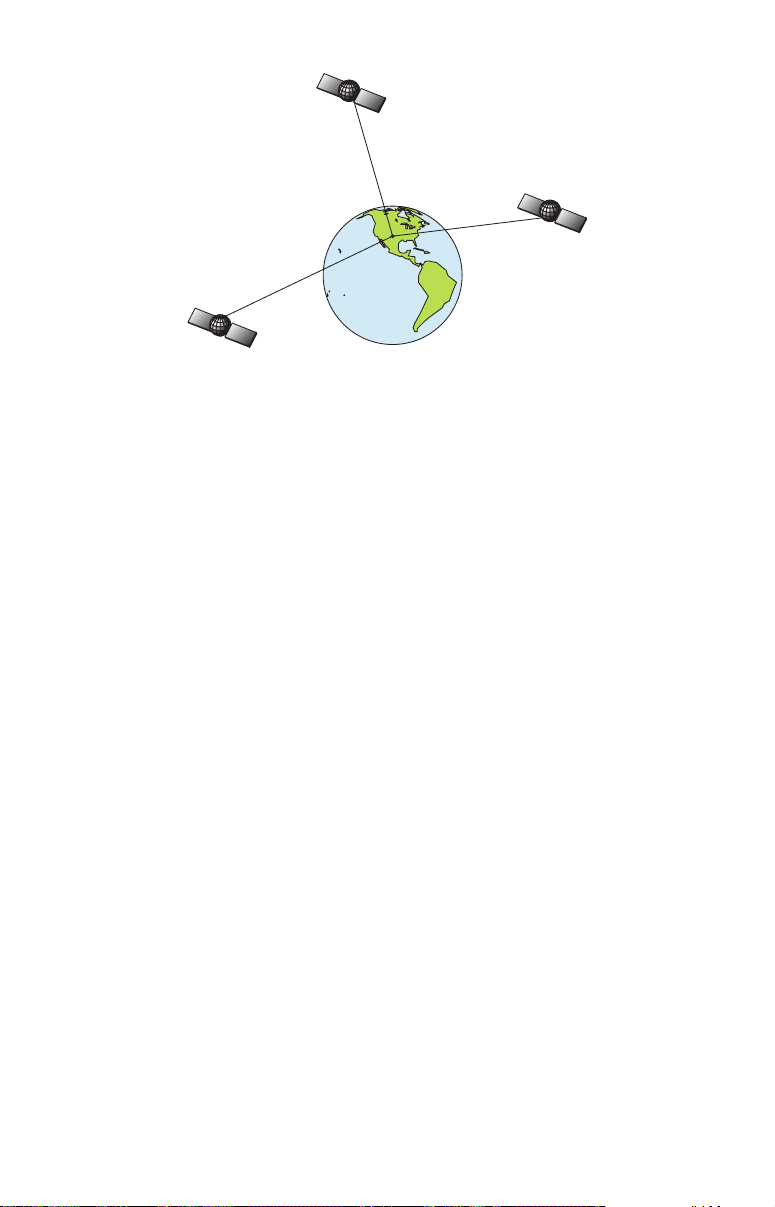
A minimum of three satellites are required to determine a 2D fix.
The system requires signal reception from three satellites in order to
determine a position. This is called a 2D fix. It takes four satellites to
determine both position and elevation (your height above sea level —
also called altitude.) This is called a 3D fix.
Remember, the unit must have a clear view of the satellites in order to
receive their signals. Unlike radio or television signals, GPS works at
very high frequencies. These signals can be easily blocked by trees,
buildings, an automobile roof, even your body.
Like most GPS receivers, LMS-320 doesn’t have a compass or any other
navigation aid built inside. It relies solely on the signals from the satellites to calculate a position. Speed, direction of travel, and distance
are all calculated from position information. Therefore, in order for
LMS-320 to determine direction of travel, you must be moving and the
faster, the better. This is not to say that it won’t work at walking or
trolling speeds — it will. There will simply be more "wandering" of the
data shown on the display.
GPS is plenty accurate for route navigation, but the U.S. Federal Aviation Administration has special needs for aircraft traffic control that go
beyond basic GPS. The FAA has a plan under way to boost GPS performance even further with its Wide Area Augmentation System, or
WAAS. This GPS add-on will include a time control element that will
help airliners fly closer together while avoiding collisions. In addition to
carefully spacing airplanes along travel corridors, WAAS will eventually make instrument landings and takeoffs more accurate as it replaces existing aviation navigation systems.
Non aviators can use WAAS signals to make their GPS navigation even
more accurate. Your LMS-320 receives both GPS and WAAS signals.
However, WAAS has some limits you should know about.
9
Page 18

First, the U.S. government has not completed construction of the WAAS
system, so it is not yet fully operational. The ground stations are in
place, but only a few of the needed WAAS satellites have been launched.
WAAS can boost the accuracy of land GPS navigation, but the system is
designed for aircraft. The satellites are in a fixed orbit around the
Equator, so they appear very low in the sky to someone on the ground
in North America. Aircraft and vessels on open water can get consistently good WAAS reception, but terrain, foliage or even large man-made
structures frequently block the WAAS signal from ground receivers.
You'll find that using your GPS receiver is both easy and amazingly
accurate. It’s easily the most accurate method of electronic navigation
available to the general public today. Remember, however, that this
receiver is only a tool. Always have another method of navigation available, such as a map or chart and a compass.
Also remember that this unit will always show navigation information
in the shortest line from your present position to a waypoint, regardless
of terrain! It only calculates position, it can’t know what’s between you
and your destination, for example. It’s up to you to safely navigate
around obstacles, no matter how you’re using this product.
How to use this manual: typographical conventions
Many instructions are listed as numbered steps. The keypad and arrow
"keystrokes" appear as boldface type. So, if you're in a real hurry (or
just need a reminder), you can skim the instructions and pick out what
menu command to use by finding the boldface command text. The following paragraphs explain how to interpret the text formatting for
those commands and other instructions:
Arrow Keys
The arrow keys control the movement of dotted cross-hair lines on your
mapping screen called the cursor. The arrow keys also control a horizontal line depth cursor on the sonar screen. The arrow keys help you
move around the menus so you can execute different commands. They
are represented by symbols like these, which denote the down arrow
key, the up arrow, the left arrow and the right arrow: ↓ ↑ ← →.
Keyboard
The other keys perform a variety of functions. When the text refers to a
key to press, the key is shown in bold, sans serif type. For example, the
"Enter/Icons" key is shown as
.
MENU
Menu Commands
A menu command or a menu option will appear in small capital letters, in
and the "Menu" key is shown as
ENT
10
Page 19

a bold sans serif type like this:
OUTE PLANNING
R
. These indicate that you are
to select this command or option from a menu or take an action of some
kind with the menu item. Text that you may need to enter or file names
you need to select are show in italic type, such as trail name.
Instructions = Menu Sequences
Most functions you perform with LMS-320 are described as a sequence
of key strokes and selecting menu commands. We've written them in a
condensed manner for quick and easy reading.
For example, instructions for navigating a trail would look like this:
1. From the Map Page, press
2. Press ↓ to Trail 1|
ENT
|→|↓ to
MENU|MENU
AVIGATE
N
|↓ to
|
ENT
MY T
.
RAILS
|
ENT
.
3. You are asked to wait while it converts the trail into a route.
4. The wait message disappears and the unit begins showing
navigation information along the trail. Now, begin moving and
follow your LMS-320.
Translated into complete English, step 1 above would mean: "Start on
the Map Page. Press the Menu key twice. Next, repeatedly press (or
press and hold) the down arrow key to scroll down the menu and select
(highlight) the My Trails menu command. Finally, press the Enter key."
Step 2 would mean: "Press the down arrow key repeatedly to scroll to
the trail named Trail 1, and press Enter. Next, press the right arrow
key and then the down arrow key to highlight the Navigate command,
then press Enter."
11
Page 20

Notes
12
Page 21

Section 2:
Installation & Accessories
Preparations
You can install the sonar and GPS systems in some other order if you
prefer, but we recommend this installation sequence:
CAUTION:
You should read over this entire installation section before drilling any holes in your vehicle or vessel!
1. Determine the approximate location for the sonar/GPS unit, so you
can plan how and where to route the cables for the antenna, transducer
and power. This will help you make sure you have enough cable length
for the desired configuration.
2. Determine the approximate location for the transducer and its cable
route.
3. Determine the approximate location for the GPS antenna module
and its cable route.
4. Determine the location of your battery or other power connection,
along with the power cable route.
5. Install the transducer and route the transducer cable to the sonar/GPS unit.
6. Install the GPS antenna and route the antenna cable to the sonar/GPS unit.
7. Install the power cable and route it to the sonar/GPS unit.
8. Mount the sonar/GPS unit.
Transducer Installation
These instructions will help you install your Skimmer
transom, on a trolling motor or inside a hull. These instructions cover
both single- and dual-frequency Skimmer transducers. Please read all
instructions before proceeding with any installation.
The smaller single-frequency Skimmers typically use a one-piece,
stainless steel mounting bracket. The larger dual-frequency Skimmers
typically use a two-piece, plastic mounting bracket. The trolling motor
mount uses a one-piece plastic bracket with an adjustable strap.
These are all "kick-up" mounting brackets. They help prevent damage if
the transducer strikes an object while the boat is moving. If the trans-
13
transducer on a
Page 22

ducer does "kick-up," the bracket can easily be pushed back into place
without tools.
Read these instructions carefully before attempting the installation.
Determine which of the mounting positions is right for your boat. Use
extreme care if mounting the transducer inside the hull, because once it
is epoxied into position, the transducer usually cannot be removed.
Remember, the transducer installation is the most critical part
of a sonar installation.
Recommended Tools and supplies
If you prefer the option of routing the cable through the transom, you
will need a 1" drill bit. A transom mount requires use of a high quality,
marine grade above- or below-waterline caulking compound. The following installation types also call for these recommended tools and required supplies (supplies are not included):
Single-frequency transom installations
Tools include: two adjustable wrenches, drill, #29 (0.136") drill bit, flathead screwdriver. Supplies: none.
Dual-frequency transom installations
Tools: two adjustable wrenches, drill, #20 (0.161") drill bit, flat-head
screwdriver. Supplies: four, 1" long, #12 stainless steel slotted wood
screws.
Single-frequency trolling motor installations
Tools: two adjustable wrenches, flat-head screwdriver. Supplies: plastic
cable ties.
Shoot-through hull installations
Tools: these will vary depending on your hull's composition. Consult your
boat dealer or manufacturer. Supplies: 100 grit sandpaper, good quality
epoxy adhesive.
Selecting a Transducer Location
1. The transducer must be placed in a location that has a smooth flow of
water at all times. If the transducer is to be mounted inside the hull,
then the chosen location must be in the water at all times. If the
transducer is not placed in a smooth flow of water, interference
caused by bubbles and turbulence will show on the sonar's display in
the form of random lines or dots whenever the boat is moving.
NOTE:
Some aluminum boats with strakes or ribs on the outside of the
hull create large amounts of turbulence at high speed. These boats
typically have large outboard motors capable of propelling the boat
14
Page 23
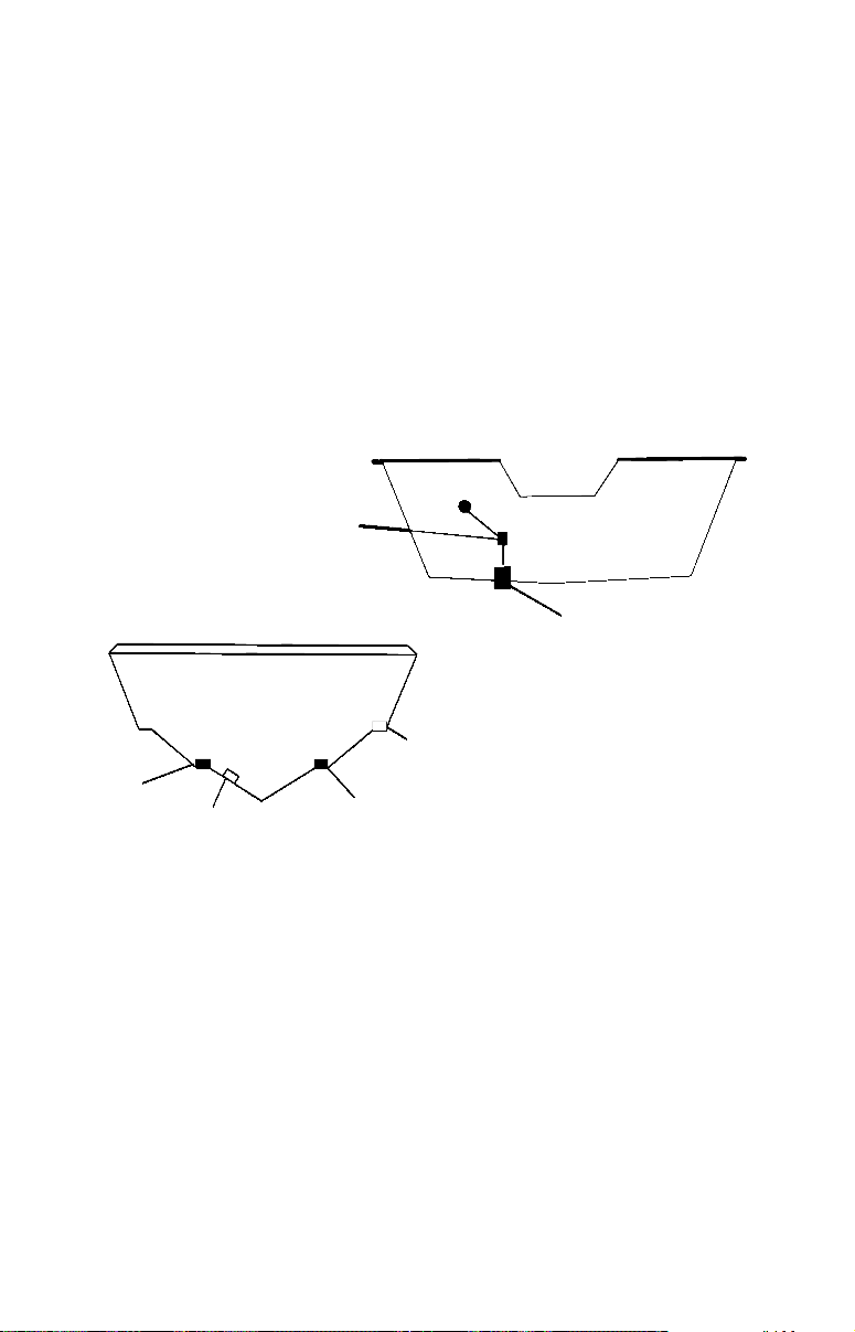
at speeds faster than 35 mph. Typically, a good location on aluminum boats is between the ribs closest to the engine.
2. The transducer should be installed with its face pointing straight
down, if possible.
3. If the transducer is mounted on the transom, make sure it doesn't inter-
fere with the trailer or hauling of the boat. Also, don't mount it closer
than approximately one foot from the engine's lower unit. This will prevent cavitation (bubble) interference with propeller operation.
4. If possible, route the transducer cable away from other wiring on the
boat. Electrical noise from engine wiring, bilge pumps and aerators
can be displayed on the sonar's screen. Use caution when routing the
transducer cable around these wires.
CAUTION: Clamp the transducer cable to transom near
the transducer. This will help
prevent the transducer from
entering the boat if it is
knocked off at high speed.
Good location
Poor location
Good
location
Poor angle
Good and poor transducer locations.
Good location
How low should you go?
For most situations, you should install your Skimmer transducer so
that its centerline is level with the bottom of the boat hull. This will
usually give you the best combination of smooth water flow and protection from bangs and bumps.
15
Page 24
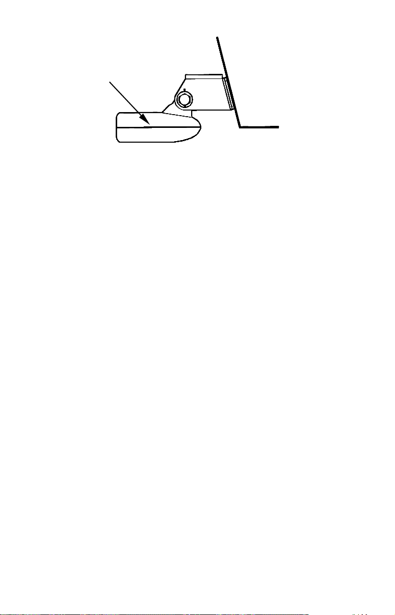
Transducer
centerline
Align transducer centerline with hull bottom.
Transom
Hull bottom
However, there are times when you may need to adjust the transducer
slightly higher or lower. (The slots in the mounting brackets allow you
to loosen the screws and slide the transducer up or down.) If you frequently lose bottom signal lock while running at high speed, the transducer may be coming out of the water as you cross waves or wakes.
Move the transducer a little lower to help prevent this.
If you cruise or fish around lots of structure and cover, your transducer
may be frequently kicking up from object strikes. If you wish, you may
move the transducer a little higher for more protection.
There are two extremes you should avoid. Never let the edge of the
mounting bracket extend below the bottom of the hull. Never let the
bottom – the face – of the transducer rise above the bottom of the hull.
Shoot-thru-hull vs. Transom Mounting
Typically, shoot-thru-hull installations give excellent high speed operation and good to excellent depth capability. There is no possibility of
damage from floating objects. It can't be knocked off when docking or
loading on the trailer.
However, the shoot-thru-hull installation does have its drawbacks.
First, some loss of sensitivity does occur, even on the best hulls. This
varies from hull to hull, even from different installations on the same
hull. This is caused by differences in hull lay-up and construction.
Second, the transducer angle cannot be adjusted for the best fish
arches. This can be a problem on some hulls that sit with the bow high
when at rest or at slow trolling speeds. Follow the procedure listed in
the shoot-thru-hull installation section at the end of this lesson to determine if you can satisfactorily shoot through the hull.
TRANSOM TRANSDUCER ASSEMBLY AND MOUNTING
The best way to install these transducers is to loosely assemble all of the
parts first, place the transducer's bracket against the transom and see if
you can move the transducer so that it's parallel with the ground.
16
Page 25
The following instructions sometimes vary depending on the mounting
bracket that came with your transducer. Single-frequency Skimmers
come with a one-piece stainless steel bracket, while dual-frequency
Skimmers come with a two-piece plastic mounting bracket. Use the set of
instructions that fits your model.
1. Assembling the bracket.
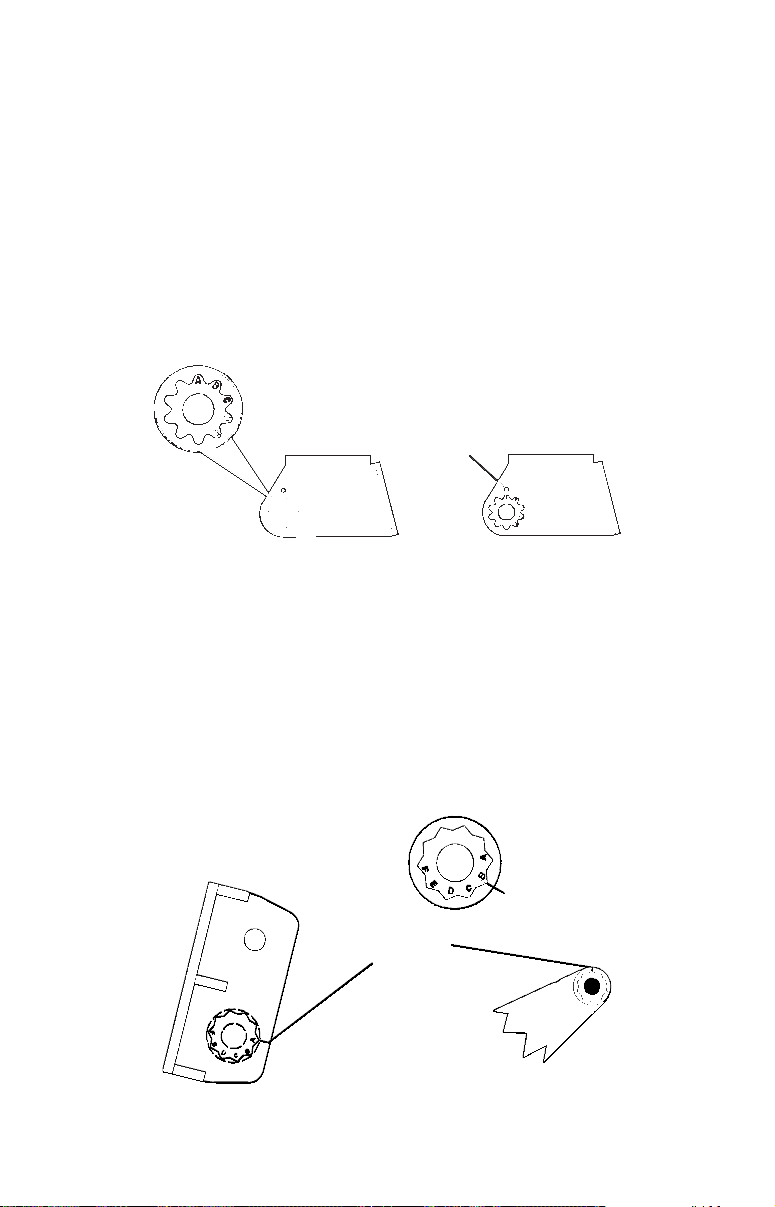
A. One-piece bracket: Press the two small plastic ratchets into the
sides of the metal bracket as shown in the following illustration. Notice
there are letters molded into each ratchet. Place each ratchet into the
bracket with the letter "A" aligned with the dot stamped into the metal
bracket. This position sets the transducer's coarse angle adjustment for a
14° transom. Most outboard and stern-drive transoms have a 14° angle.
Dot
Align plastic ratchets in bracket.
B. Two-piece bracket: Locate the four plastic ratchets in the transducer's hardware package. Press two ratchets into the sides of the plastic bracket and two on either side of the transducer as shown in the following illustrations. Notice there are letters molded into each ratchet.
Place the ratchets into the bracket with the letter "A" aligned with the
alignment mark molded into the bracket. Place the ratchets onto the
transducer with the letter "A" aligned with the 12 o'clock position on
the transducer stem. These positions set the transducer's coarse angle
adjustment for a 14° transom. Most outboard and stern-drive transoms have a 14° angle.
Alignment letters
Alignment
positions
Transducer
Transducer bracket
Insert and align ratchets.
17
Page 26
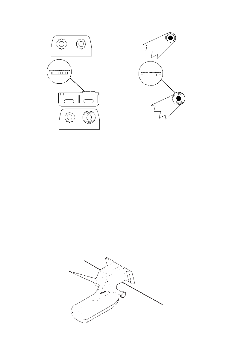
Transducer
bracket
Transducer
Ratchet
Add ratchets to bracket and transducer.
Ratchet
2. Aligning the transducer on the transom.
A. One-piece bracket: Slide the transducer between the two ratch-
ets. Temporarily slide the bolt though the transducer assembly and
hold it against the transom. Looking at the transducer from the side,
check to see if it will adjust so that its face is parallel to the ground.
If it does, then the "A" position is correct for your hull.
If the transducer's face isn't parallel with the ground, remove the
transducer and ratchets from the bracket. Place the ratchets into the
holes in the bracket with the letter "B" aligned with the dot stamped
in the bracket.
Reassemble the transducer and bracket and place them against the
transom. Again, check to see if you can move the transducer so it's
parallel with the ground. If you can, then go to step 3A. If it doesn't,
repeat step 2A, but use a different alignment letter until you can
place the transducer on the transom correctly.
Ratchets
Insert bolt and check transducer position on transom.
18
Page 27
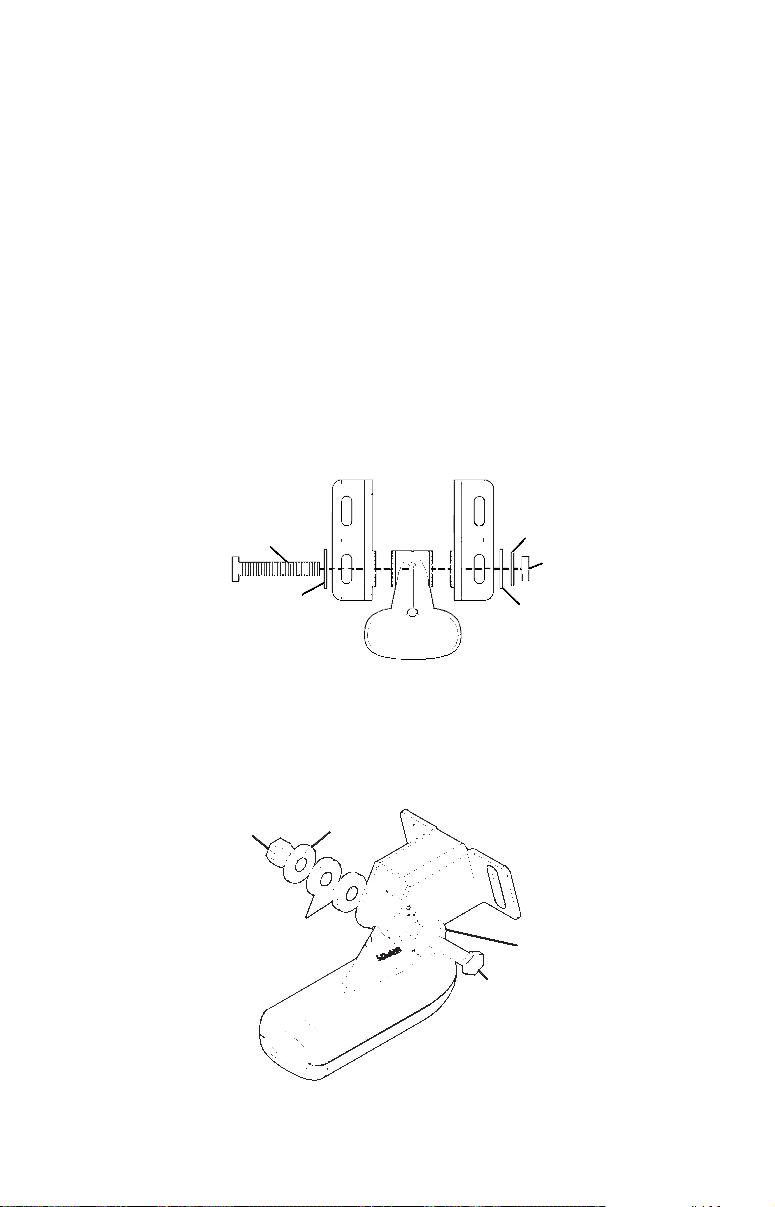
B. Two-piece bracket: Assemble the transducer and bracket as shown
in the following figure. Temporarily slide the bolt though the transducer
assembly but don't tighten the nut at this time. Hold the assembled
transducer and bracket against the transom. Looking at the transducer
from the side, check to see if it will adjust so that its face is parallel to
the ground. If it does, then the "A" positions are correct for your hull.
If the transducer's face isn't parallel with the ground, remove and
disassemble the transducer and ratchets. Place the ratchets into the
bracket holes with the letter "B" aligned with the bracket alignment
mark. Place them on the transducer aligned with the 12 o'clock position on the transducer stem.
Reassemble the transducer and bracket and place them against the
transom. Again, check to see if you can move the transducer so it's
parallel with the ground. If you can, then go to step 3B. If it doesn't,
repeat step 2B, but use a different alignment letter until you can
place the transducer on the transom correctly.
Bolt
Flat washer
Assemble transducer and bracket.
Lock washer
Nut
Flat washer
3. Assembling the transducer.
A. One-piece bracket: Once you determine the correct position for
the ratchets, assemble the transducer as shown in the following figure. Don't tighten the lock nut at this time.
Metal
Nut
Rubber
washers
Assemble transducer and bracket.
washer
Metal washer
Bolt
19
Page 28
B. Two-piece bracket: Once you determine the correct position for
the ratchets, assemble the transducer as shown in the figure in step
2B. Don't tighten the lock nut at this time.
4. Drilling mounting holes.
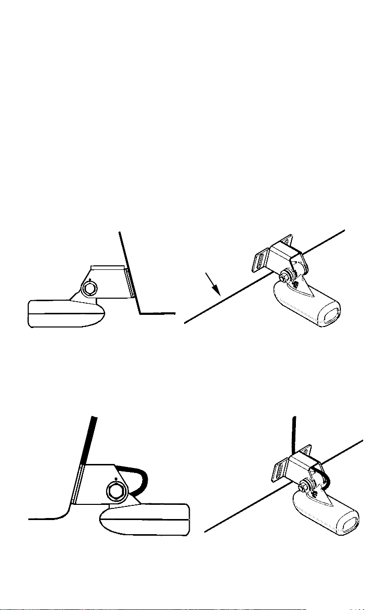
Hold the transducer and bracket assembly against the transom. The
transducer should be roughly parallel to the ground. The transducer's centerline should be in line with the bottom of the hull. Don't
let the bracket extend below the hull!
Mark the center of each slot for the mounting screw pilot holes. You
will drill one hole in the center of each slot.
Drill the holes. For the one-piece bracket, use the #29 bit (for the #10
screws). For the two-piece bracket, use the #20 bit (for the #12
screws).
Transom
Transom
Position transducer mount on transom and mark mounting holes.
Side view shown at left and seen from above at right.
5. Attaching transducer to transom.
A. One-piece bracket: Remove the transducer from the bracket and
re-assemble it with the cable passing through the bracket over the
bolt as shown in the following figures.
For single-frequency Skimmer, route cable over bolt and through
bracket. Side view shown at left and seen from above at right.
20
Page 29
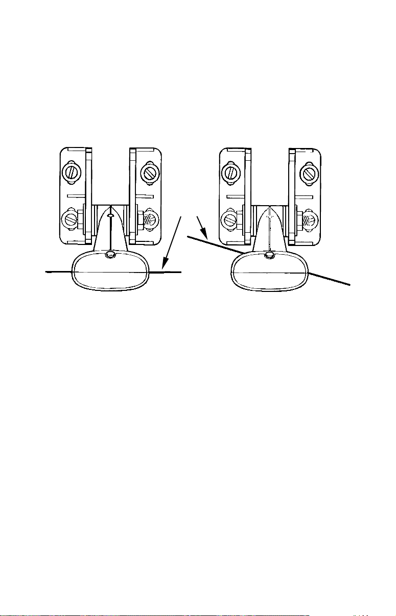
Both bracket types: Attach the transducer to the transom. Slide the
transducer up or down until it's aligned properly with the bottom of
the hull as shown in the preceding and following figures. Tighten the
bracket's mounting screws, sealing them with the caulking compound.
Adjust the transducer so that it's parallel to the ground and tighten
the nut until it touches the outer washer, then add 1/4 turn. Don't
over tighten the lock nut! If you do, the transducer won't "kick-up" if
it strikes an object in the water.
Bottom
of
hull
Flat-bottom hull Deep-"vee" hull
Align transducer centerline with hull bottom and attach transducer to
transom. Rear view of dual-frequency Skimmer shown.
6. Route the transducer cable through or over the transom to the sonar
unit. Make sure to leave some slack in the cable at the transducer. If
possible, route the transducer cable away from other wiring on the
boat. Electrical noise from the engine's wiring, bilge pumps, VHF radio
wires and cables, and aerators can be picked up by the sonar. Use caution when routing the transducer cable around these wires.
WARNING:
Clamp the transducer cable to the transom close to the
transducer. This can prevent the transducer from entering the boat if it is knocked off at high speed.
If you need to drill a hole in the transom to pass the connector through,
the required hole size be 1".
CAUTION:
If you drill a hole in the transom for the cable, make sure it is located above the waterline. After installation, be sure to seal the
hole with the same marine grade above- or below-waterline sealant used for the mounting screws.
21
Page 30
7. Make a test run to determine the results. If the bottom is lost at
high speed, or if noise appears on the display, try sliding the transducer bracket down. This puts the transducer deeper into the water,
hopefully below the turbulence causing the noise. Don't allow the
transducer bracket to go below the bottom of the hull!
TROLLING MOTOR BRACKET INSTALLATION
(single-frequency only)
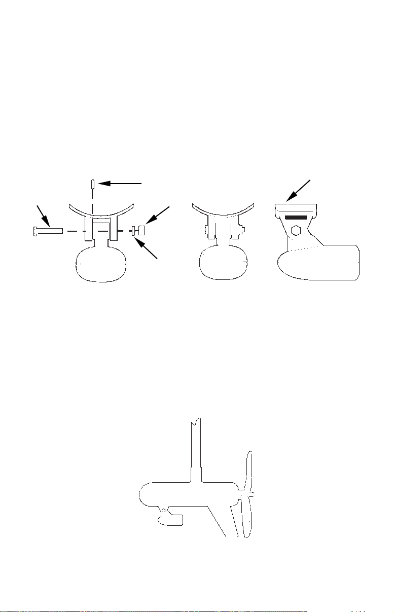
1. Attach the optional TMB-S bracket to the transducer as shown in the
following figure, using the hardware supplied with the transducer.
(Note: The internal tooth washer is supplied with the TMB-S.)
TMB-S bracket
Bolt
Internal tooth washer
Nut
Flat washer
Attach motor mounting bracket to transducer.
2. Slide the adjustable strap supplied with the TMB-S through the slot
in the transducer bracket and wrap it around the trolling motor. Position the transducer to aim straight down when the motor is in the
water. Tighten the strap securely.
3. Route the transducer cable alongside the trolling motor shaft. Use
plastic ties (not included) to attach the transducer cable to the trolling motor shaft. Make sure there is enough slack in the cable for the
motor to turn freely. Route the cable to the sonar unit and the transducer is ready for use.
Transducer mounted on trolling motor, side view.
22
Page 31
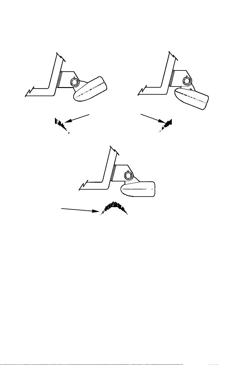
TRANSDUCER ORIENTATION AND FISH ARCHES
If you do not get good fish arches on your display, it could be because
the transducer is not parallel with the ground when the boat is at rest
in the water or at slow trolling speeds.
Partial fish arches
Transducer aimed
too far back
Transducer aimed
too far forward
Full fish arch
Proper transducer angle
Transducer angles and their effects on fish arches.
If the arch slopes up – but not back down – then the front of the transducer is too high and needs to be lowered. If only the back half of the
arch is printed, then the nose of the transducer is angled too far down
and needs to be raised.
NOTE:
Periodically wash the transducer's face with soap and water to remove any oil film. Oil and dirt on the face will reduce the sensitivity
or may even prevent operation.
SHOOT-THRU-HULL PREPARATION
The transducer installation inside a fiberglass hull must be in an area
that does not have air bubbles in the resin or separated fiberglass layers. The sonar signal must pass through solid fiberglass. A successful
23
Page 32
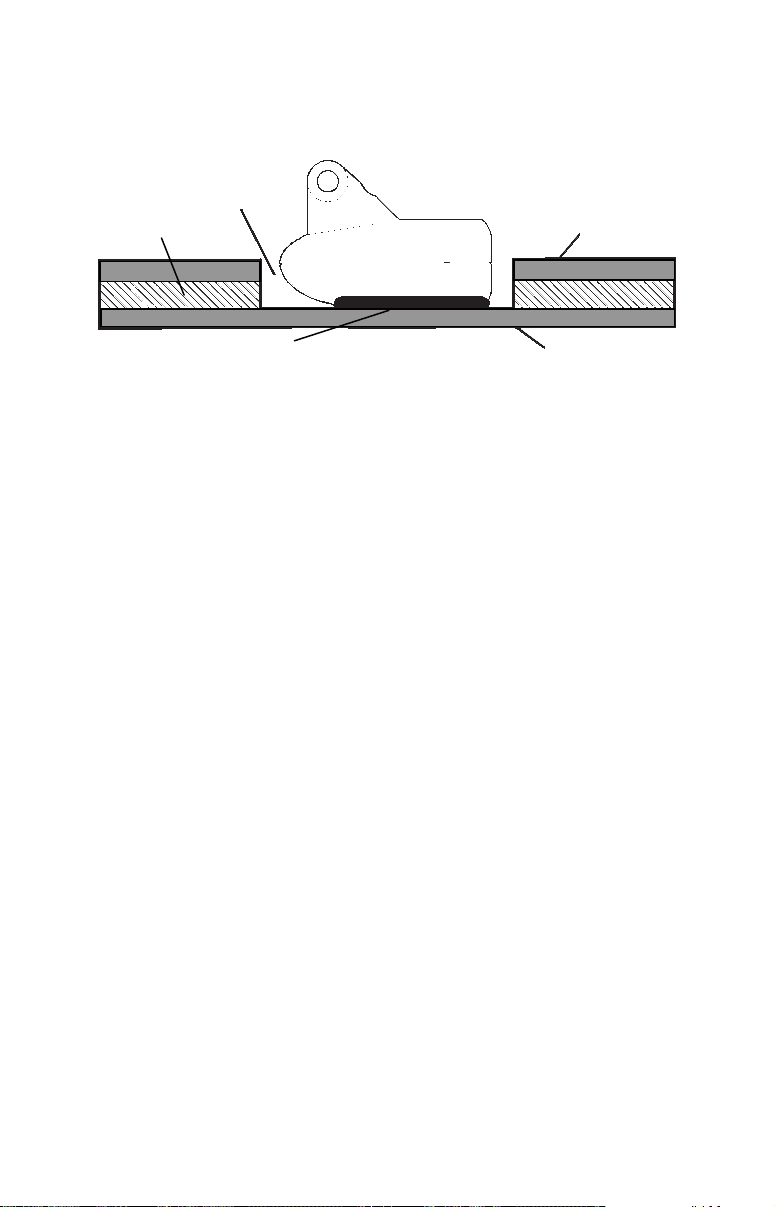
transducer installation can be made on hulls with flotation materials
(such as plywood, balsa wood or foam) between layers of fiberglass if
the material is removed from the chosen area.
Fill with epoxy
Flotation material
Inner hull
Epoxy to hull first
Epoxy the transducer to a solid portion of the hull.
Outer hull
For example, some (but not all) manufacturers use a layer of fiberglass,
then a core of balsa wood, finishing with an outer layer of fiberglass.
Removing the inner layer of fiberglass and the balsa wood core exposes
the outer layer of fiberglass. The transducer can then be epoxied directly to the outer layer of fiberglass. After the epoxy cures, the hull is
watertight and structurally sound. Remember, the sonar signal must
pass through solid fiberglass. Any air bubbles in the fiberglass or the
epoxy will reduce or eliminate the sonar signals.
WARNING:
Do not remove any material from your inner hull unless
you know the hull's composition. Careless grinding or
cutting on your hull can result in damage that could sink
your boat. Contact your boat dealer or manufacturer to
confirm your hull specifications.
To choose the proper location for thru-hull mounting, anchor the boat in
60 feet of water. Add a little water to the sump of the boat. Plug the
transducer into the sonar unit, turn it on, then hold the transducer over
the side of the boat. Adjust the sensitivity and range controls until a second bottom echo is seen on the display. (You will need to turn off both
automatic and ASP.) Don't touch the controls once they've been set.
Next, take the transducer out of the water and place it in the water in
the sump of the boat. Observe the sonar signal to see if there is a noticeable decrease in sensitivity. The second bottom signal may disappear and the bottom signal may decrease in intensity.
Move the transducer around to find the best location. If the sensitivity
control must be increased greatly to compensate, then the transducer
should be mounted on the outside of the hull. If not, then mark the lo-
24
Page 33
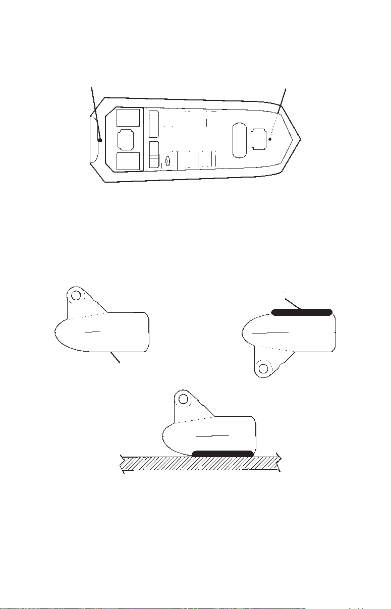
cation that shot through the hull the best and follow the instructions on
the following pages for a shoot-thru-hull mounting.
Transducer location
(high speed)
Shoot-thru-hull transducer locations for
high speed or trolling speed operation.
Transducer location
(trolling speed)
Shoot-thru-hull Installation
1. Make sure the area is clean, dry and free of oil or grease, then sand
both the inside surface of the hull and the face of the transducer with
100 grit sandpaper. The surface of the hull must be flat so the entire
transducer face is in contact with the hull prior to bonding.
Spread epoxy here
Sand this surface
Epoxy transducer to hull.
2. Follow the instructions on the epoxy package and mix it thoroughly.
Do not mix it too fast, because it will cause bubbles to form in the epoxy. Apply a small amount on the face of the transducer as shown
above, then spread a small amount onto the sanded area on the hull.
25
Page 34

Place the transducer into the epoxy, twisting and turning it to force
any air bubbles out from under the transducer face. The face of the
transducer should be parallel with the hull, with a minimum amount
of epoxy between the hull and transducer. After the epoxy dries,
route the cable to the sonar unit.
Speed/Temperature Sensors
This unit accepts up to three temperature sensors which can monitor
surface water, live well, air and virtually any other temperature. If you
want to use more than one temperature sensor or a speed sensor, you
must purchase the optional MY-4X adapter cable. You also need to be
careful when purchasing the temperature sensors, because each temperature sensor has its own fixed electronic "address." The sensors are
labeled "Water," "T-2" (or Temp-2) and "T-3" (or Temp-3).
The first "Water" temperature sensor is built into the transducer. This
is the sensor that measures surface water temperature. If you want two
(or more) temperature readings from other locations, you'll need to use
the proper sensors. For example, you can't use two additional T-3 sensors. The sensors that fit this unit are:
• TS-1X This sensor will over-ride the temperature sensor
built into the transducer and over-ride the temperature sensor in a ST-TGY combination sensor. (This sensor is not recommended.)
• TS-2X One sensor for "T-2" temperature display.
• TS-3X One sensor for "T-3" temperature display.
• SP-X One speed sensor for "Speed" display.
• ST-TGY This combination sensor will provide speed and
temperature readings, but the temperature
reading will be displayed as the "Water" temperature because it will over-ride the temperature sensor in the transducer. (This sensor is
not recommended.)
See the wiring diagram on the following page for temperature and
speed sensor combinations.
26
Page 35
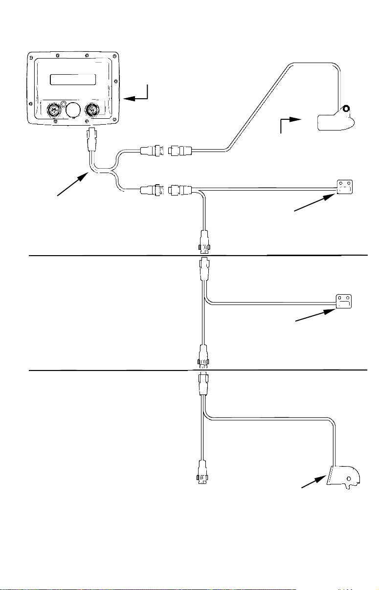
MY-4X
Cable
Three-temperature
sensor installation
Sensor Chart
LMS-320
rear view
Temperature
sensor built into
transducer
Two-temperature
sensor installation
TS-2X
temperature sensor
TS-3X
temperature sensor
Three-temperature sensor
installation with speed
SP-X speed sensor
27
Page 36
Optional Speed Sensor Installation
All the units in this series can display speed and distance traveled, but
only the LMS-320DF comes packed with a speed sensor. If you wish to
purchase an optional additional sensor for your unit, refer to the accessory ordering information inside the back cover of this manual. The
following instructions describe how to install the speed sensor.
Recommended tools for this job include: drill, 7/8" drill bit, 1/8" drill bit
for pilot holes, screwdriver. Required supplies for this job include: four
#8 stainless steel wood screws (3/4" long), high quality, marine grade
above- or below-waterline caulking compound.
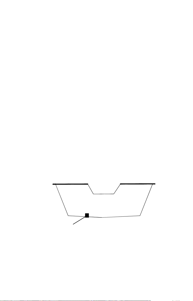
First find a location on the boat's transom where the water flow is
smoothest. Don't mount the sensor behind strakes or ribs. These will
disturb the water flow to the speed sensor. Make sure the sensor will
remain in the water when the boat is on plane. Also make sure the location doesn't interfere with the boat's trailer. Typically, the sensor is
mounted about one foot to the side of the transom's centerline.
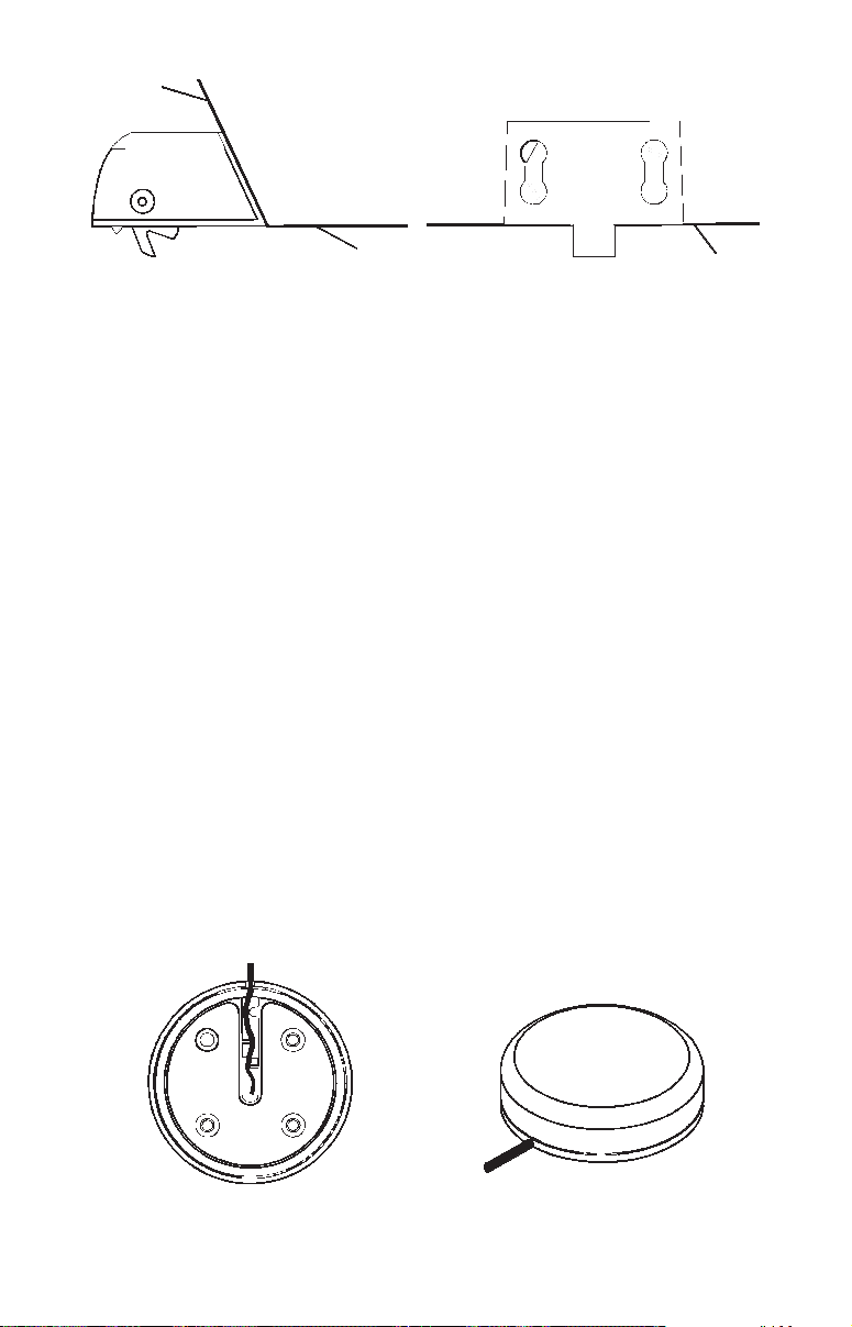
Once you've determined the proper location for the unit, place the sensor on the transom. The bottom of the bracket should be flush with the
hull's bottom. Using the sensor as a template, mark the hull for the
screws' pilot holes. Drill four 1/8" holes, one in each end of the slots.
Mount the sensor to the hull using #8 stainless steel wood screws (not
included). Use a high quality, marine grade above- or below-waterline
caulking compound to seal the screws. Make sure the sensor is flush
with the bottom of the hull and tighten the screws.
Good location
Stern view showing good location for mounting sensor on transom.
28
Page 37
Transom
Bottom of hull
Speed sensor mounting configuration:
side view (left) and rear view (right.)
Bottom of hull
If the base of the transom has a radius, fill the gap between the transom and the sensor with the caulking compound. This will help ensure
a smooth water flow.
Route the sensor's cable through or over the transom to the sonar unit.
If you need to drill a hole in the transom to pass the connector through,
the required hole size is 7/8".
CAUTION:
If you drill a hole in the transom for the cable, make sure it is located above the waterline. After installation, be sure to seal the
hole with the same marine grade above- or below-waterline sealant used for the screws.
The sensor is now ready for use. Connect the sensor to the in-line connector on the MY-4X adapter cable. If you have any questions concerning the installation of the sensor, please contact your local boat dealer.
GPS Antenna/Receiver Module
The LMS-320 series package includes the LGC-12w GPS module. This
device contains the unit's external antenna and receiver for GPS and
WAAS signals. The antenna/receiver module comes with a 25-foot extension cable. This module can be mounted on a flat surface or pole, or
a magnet is included for temporary mounting on any ferrous surface.
(The LGC-12s GPS module sold with earlier Lowrance equipment will
work with your unit, but it will not receive WAAS signals.)
LGC-12 Module, bottom view (left) and top view (right).
29
Page 38

You need to select an antenna installation location that has a clear, unobstructed view of the sky. After the module is installed, route the cable
to the LMS-320, plug it in the center socket on the back and your system is ready to use. See the module's instruction sheet, publication part
number 988-0147-39, for complete installation directions.
In an automobile, you may achieve good results by simply placing the
external antenna on the top of the dash, at the base of the windshield.
A piece of the rubber non-skid shelf liner material available in recreational vehicle supply stores will help hold the antenna in place. This
may not work well if you have a cab-over design pickup truck camper or
motor home. If dashboard reception is poor, simply relocate the antenna module elsewhere on the vehicle for a clearer view of the sky.
Power Connections
The unit works from a 12-volt battery system. For the best results, attach the power cable directly to the battery. You can attach the power
cable to an accessory or power buss, however you may have problems
with electrical interference. Therefore, it's safer to go ahead and attach
the power cable directly to the battery.
If possible, keep the power cable away from other boat wiring, especially the engine's wires. This will provide the best isolation from electrical noise. If the cable is not long enough, splice #18 gauge wire onto
it. The power cable has two wires, red and black. Red is the positive
lead, black is negative or ground. Make sure to attach the in-line fuse
holder to the red lead as close to the power source as possible.
For example, if you have to extend the power cable to the battery or
power buss, attach one end of the fuse holder directly to the battery or
power buss. This will protect both the unit and the power cable in the
event of a short. It uses a 3-amp fuse.
30
Page 39
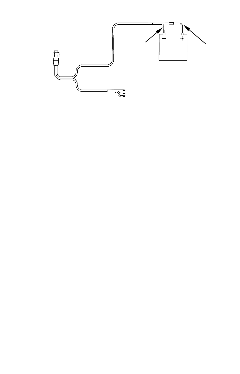
p
To unit
Power connections for the LMS-320 series sonar/GPS unit.
Black wire
Data wires
12 volt
battery
Red wire with
3 am
fuse
CAUTION:
Do not use this product without a 3-amp fuse wired into the power
cable! Failure to use a 3-amp fuse will void your warranty.
This unit has reverse polarity protection. No damage will occur if the
power wires are reversed. However, the unit will not work until the
wires are attached correctly.
An optional 8-foot, CA-4 external power cable with a cigarette lighter
adapter is available from Lowrance.
NMEA/DGPS Cable Connections
NMEA is a standard communications format for marine electronic
equipment. For example, an autopilot can connect to the NMEA interface on the LMS-320 and receive positioning information. The LMS-320
can exchange information with any device that transmits or receives
NMEA 0183 data.
DGPS is an acronym for the Differential Global Positioning System.
DGPS supplements and boosts the accuracy of basic GPS. DGPS was
developed by the U.S. Coast Guard, which is responsible for the system's operation in the United States. Since it's creation, DGPS has become the international maritime standard for marine navigation.
The most popular DGPS system relies on a grid of ground-based transmitters that send correction signals to DGPS receivers. These in turn,
connect to the GPS receiver (such as the LMS-320). Lowrance offers an
optional DGPS receiver for your unit.
31
Page 40
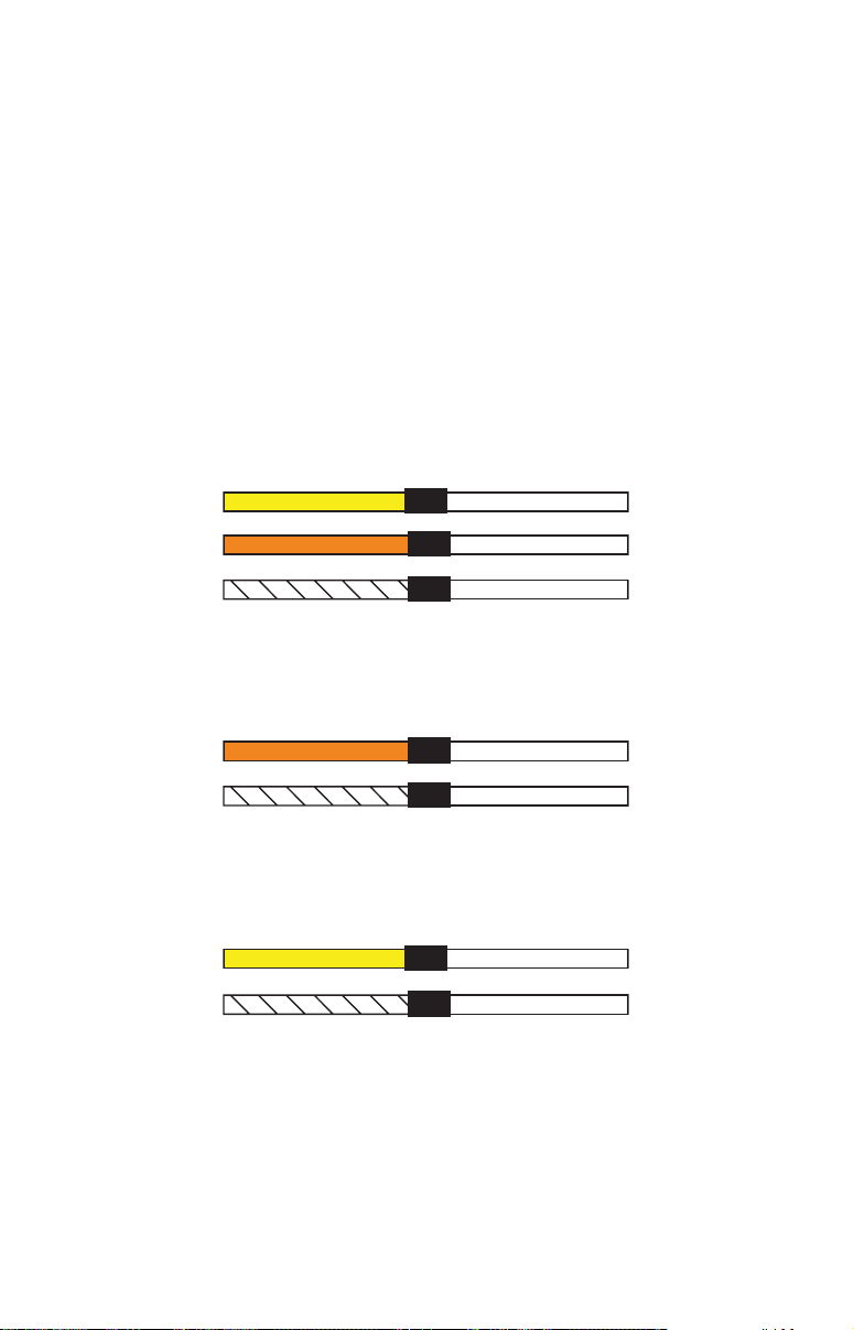
See the diagrams on the following page for general wiring connections.
Read your other product’s owner’s manual for more wiring information.
NMEA/DGPS Wiring
To exchange NMEA or DGPS data, the LMS-320 has one NMEA 0183
version 2.0 communication port. Com port one (Com-1) can be used to
receive NMEA format GPS data or DGPS data. The com port can also
transmit NMEA format GPS data to another device.
The three wires for the com port are combined with the two power
wires to form the power/data cable (see the drawing on page 33). Com-1
uses the yellow wire to transmit, the orange wire to receive and the
shield wire for signal ground.
Com-1
To LMS-320
Com-1
To LMS-320
Com-1
To LMS-320
Com-1 wiring to transmit NMEA position information
Yellow (Transmit)
Orange (Receive)
Shield (Ground)
Com-1 wiring to receive DGPS position information
from a DGPS receiver.
Orange (Receive)
Shield (Ground)
Com-1 wiring to receive NMEA position information
from some other GPS receiver.
Yellow (Transmit)
Shield (Ground)
to another NMEA-compatible device.
Receive
Transmit
Ground
NMEA Transmit
Ground
NMEA Receive
Ground
GPS Receiver
To DGPS
Receiver
To Other
To Other
Device
32
Page 41
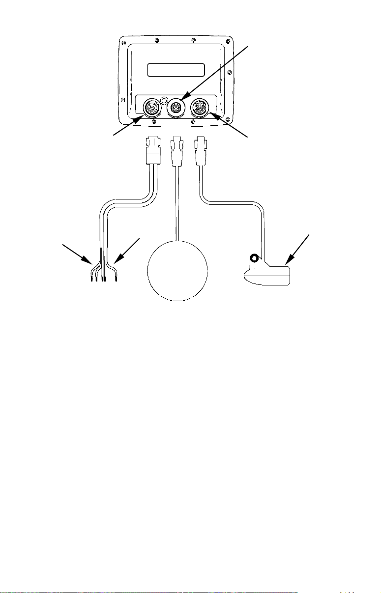
LMS-320,
rear view
GPS socket
Power/Data socket
Com port
data wires
(three)
Power wires
(two)
GPS
antenna
module
LMS-320 cable connections.
Sonar socket
Transducer
Mounting the Unit: Bracket, In-Dash or Portable
You can install the LMS-320 on the top of a dash with the supplied
gimbal bracket. It can also be installed in the dash or mounted on a
portable power supply.
If you use the supplied bracket, you may be interested in the optional
R-A-M
bracket to a swivel mount, which can be used on the dash or overhead
mounting positions. Installation instructions are supplied with the
R-A-M mounting kits.
bracket mounting system. This converts the unit's gimbal
33
Page 42
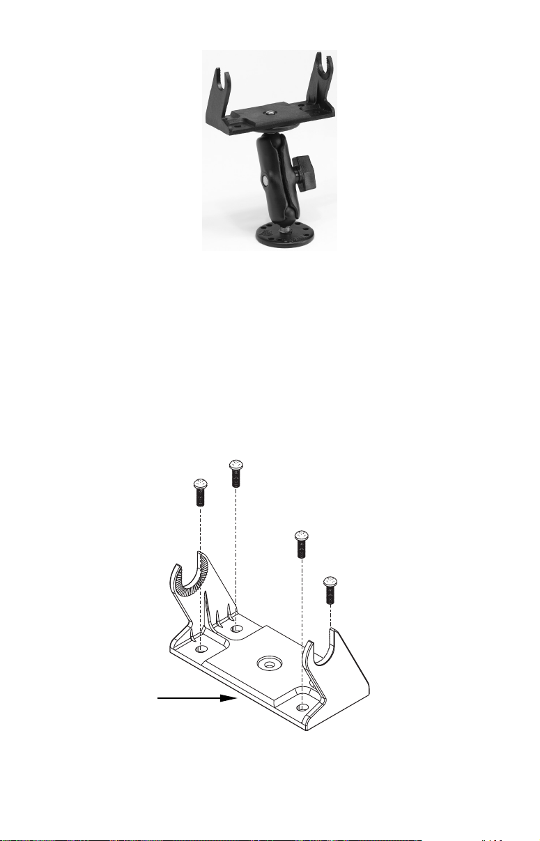
Optional R-A-M mounting system.
Bracket Installation
Mount the unit in any convenient location, provided there is clearance
behind the unit when it's tilted for the best viewing angle. You should
also make sure there is enough room behind the unit to attach the
power, transducer and GPS antenna/receiver module cables. (A drawing on the next page shows the dimensions of a gimbal-mounted LMS320 unit.)
Holes in the bracket's base allow wood screw or through-bolt mounting.
You may need to place a piece of plywood on the back side of thin fiberglass panels to reinforce the panel and secure the mounting hardware.
Front
Install the gimbal bracket. Orient the bracket so the arms slope toward
the front of your unit.
34
Page 43
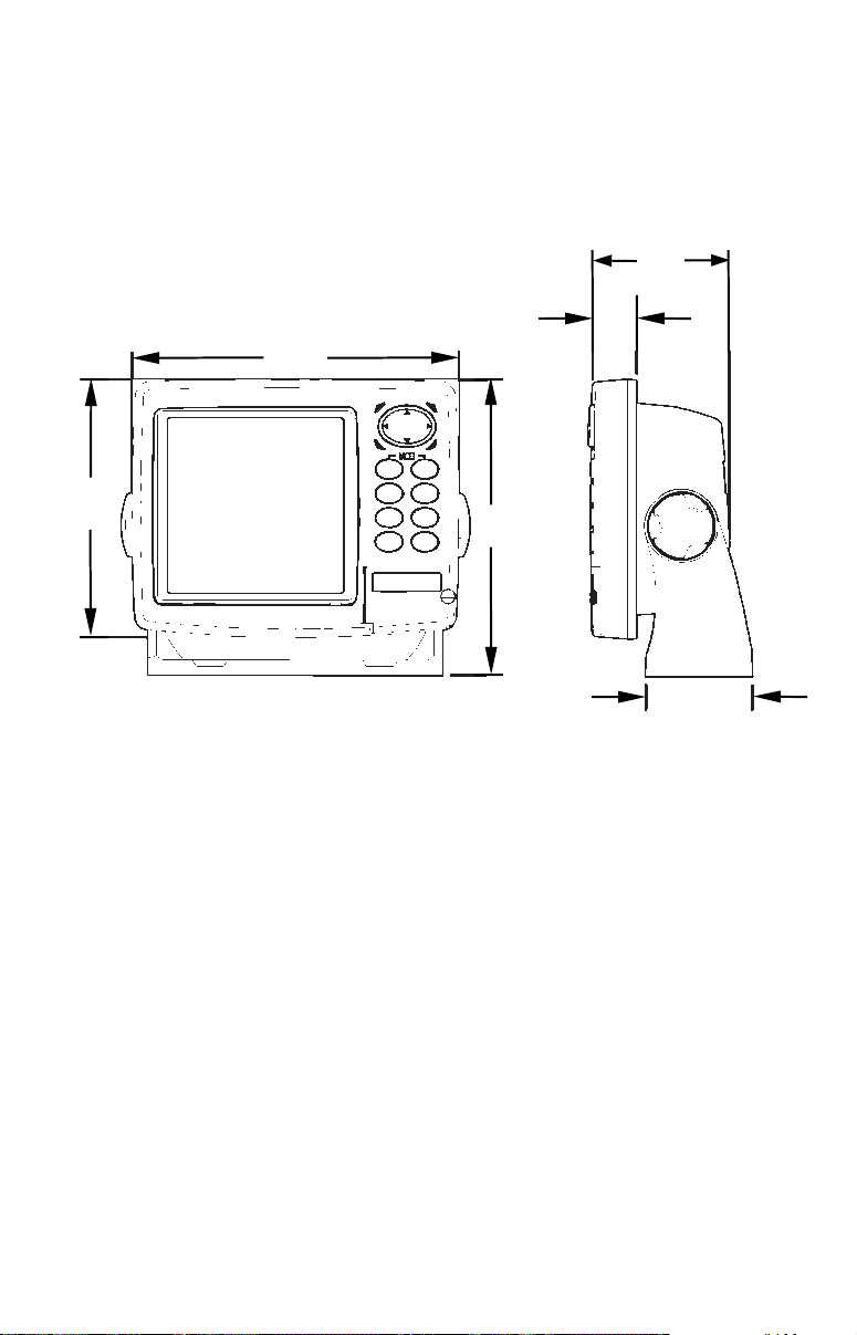
Drill a 1-inch (25.4 mm) hole in the dash for the power, transducer and
antenna cables. The best location for this hole is immediately under the
gimbal bracket location. This way, the bracket can be installed so that
it covers the hole, holds the cables in position and results in a neat installation. Some customers, however, prefer to mount the bracket to the
side of the cable hole — it's a matter of personal preference.
72.9
[2.87]
23.4
173.9
[6.85]
[0.92]
137.9
[5.43]
Millimeter
[Inch]
Front view (left) and side view (right) showing dimensions of LMS-320
sonar/GPS unit when mounted on gimbal bracket.
157.9
[6.22]
56.9
[2.24]
After drilling the hole, pass the transducer connector up through the
hole from under the dash, followed by antenna connector. Pass the
power cable's bare-wire end down though the hole from the top.
If you wish, you can fill in the hole around the cables with a good marine caulking compound. (Some marine dealers stock cable hole covers
to conceal the opening.) No matter what type of installation you prefer,
be sure to leave enough slack in the cables to allow tilting or swiveling
the unit. If you choose to fill in the hole, be sure to position the cables
against the rear edge of the hole as you apply the fill material.
Before positioning the bracket, be sure to hold the cables against the
rear edge of the hole. Then, slide the bracket over the hole and butt the
rear of the bracket base firmly against the cables, thus pinning them in
place against the side of the hole. Finally, fasten the bracket to the
dash. Attach the unit to the gimbal bracket using the supplied gimbal
knobs and washers.
35
Page 44
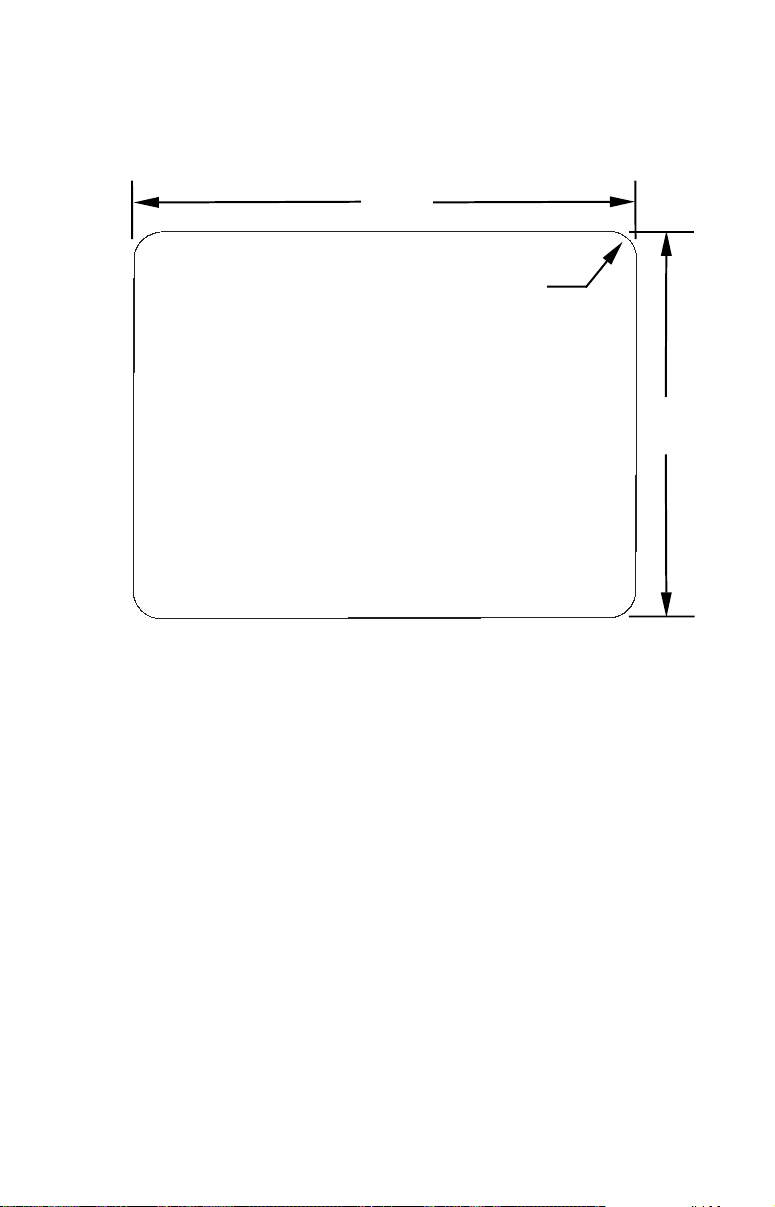
In-Dash Installation
You can mount the unit in the dash with an optional FM-5 In-Dash
Adapter Kit. The kit includes mounting hardware, a template for cutting the hole and an instruction sheet, part 988-0147-43.
146.5
[5.76]
Top
R 7.9
[0.31]
In-Dash
Template
Millimeters
[Inches]
ALWAYS VERIFY DIMENSIONS
113.5
[4.46]
In-dash mounting template for LMS-320 sonar/GPS unit, showing
dimensions. NOTE: The figure above is not printed to scale. A scaled
template (FM-5 In-Dash Adapter Kit instructions) is available for free
download from our web site, www.lowrance.com.
Portable Installation
Like many Lowrance products, the LMS-320 is capable of portable operation by using the optional PPP-11 portable power pack. The power
pack, the magnet-equipped antenna module and an optional portable
transducer expand the uses for your sonar/GPS unit. The PPP-11
makes it easy to transfer your unit from a boat to a car, recreational
vehicle, airplane or other vehicle without drilling and mounting a second bracket. You can use your unit in your own car or boat, then take it
along when riding in a friend's vehicle that's not equipped with sonar or
GPS. (Or use it as a second sonar, one for each fisherman!)
The PPP-11 Portable Power Pack can be used with eight "D" cell alkaline batteries or an optional sealed, rechargeable battery. For set-up
directions, refer to the pack's instruction sheet, part 988-0147-46.
36
Page 45
"D" cell battery
Install batteries in power pack battery adapter.
MMC or SDC Memory Card Installation
Your LMS-320 uses a MultiMedia Card to store information, such as
sonar logs, custom maps, waypoints, trails and other GPS data. The
unit can also use Secure Digital Cards (SD card or SDC) to store data.
NOTE:
Throughout this manual, we will use the term MMC, but just remember that your unit can use an MMC or SDC to store data.
Both of these solid-state flash memory devices are about the size of a
postage stamp. An SD card is slightly thicker than an MMC. As this
manual went to press, MMCs were available in storage capacities of 8
MB, 16 MB, 32 MB and 64 MB. SD cards were available in capacities of
8 MB, 16 MB, 32 MB, 64 MB, 128 and 256 MB.
Additional MMC cards are available from LEI Extras; see ordering information inside the back cover of this manual. MMCs and SD cards
are also available at many camera and consumer electronics stores.
The MMC slot is located in a compartment on the front of the case. The
compartment door is located at the lower right corner. The following
figure shows a close-up with the door opened.
37
Page 46
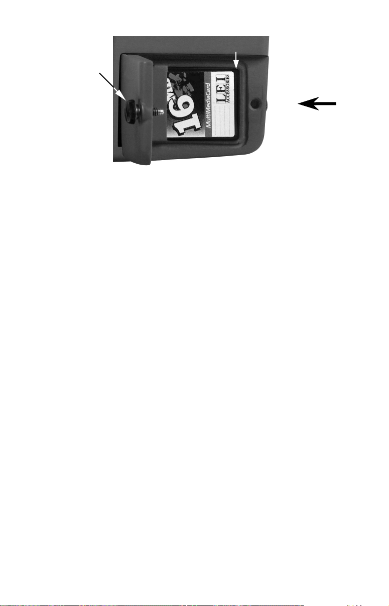
MMC groove for card removal
Thumb
screw
Memory card compartment with a 16 MB MMC card installed.
Insert card face up,
this way
To remove an MMC
1. Open the card compartment door by unscrewing the thumb screw.
The screw should only be finger tight. If it was over-tightened, use a
thumbnail, a coin or a screwdriver to open the door.
2. Use a thumbnail or fingernail to grab the groove in the bottom of the
MMC. See the figure above for the groove location.
3. Drag the MMC from the slot.
To add an MMC or SDC
1. Open the card compartment door.
2. Grasp the bottom of the MMC and push the top of the card into the
slot. Once the card is started, use your fingernails to slide it the rest of
the way to the left, until it is firmly seated in the slot.
3. Close the compartment door and fasten the thumb screw finger tight.
Other Accessories
Other LMS-320 accessories include MMC cards, MMC card readers and
MapCreate™ 6 custom mapping software for your computer. MMC card
readers are available in USB and parallel port versions.
Two switch boxes are available for this unit. The SB-7X transducer
switch box switches two transducers to one sonar unit. The SB-8X transducer switch box switches two sonar units to one transducer.
If these accessories are not available from your dealer, see the accessory ordering information on the inside back cover of this manual. Visit
our web site for a complete listing of all the available accessories for
your unit.
38
Page 47
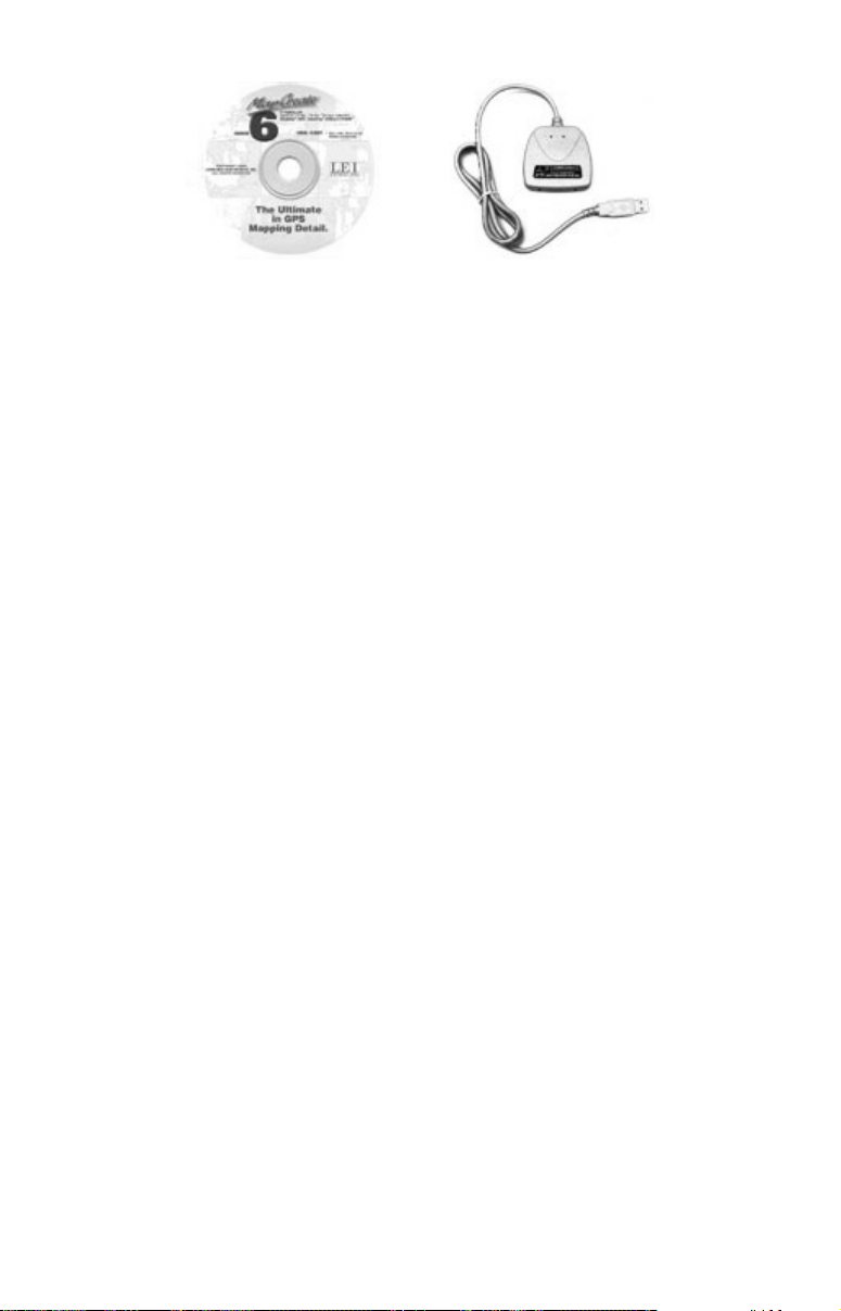
MapCreate™ 6 CD-ROM, left; MMC card reader for USB ports, right.
Now that you have your unit installed, move on to Section 3, Basic Sonar Operations. There, we'll present a series of step-by-step tutorials to
teach you the basics of LMS-320 sonar operation.
NOTE:
When you first turn the unit on, the Map Page appears. If you'd
rather start learning about GPS operation first, turn over to Section 6, Basic GPS Operations. (Remember, you don't need to read
this manual from cover-to-cover to get going. We designed it so you
can skip around to the section you want to read.)
Face Cover
Your LMS-320 comes with a white protective cover that snaps on and
off the front of the unit. This cover is intended for use when your unit
and the vehicle it's mounted in are idle.
WARNING:
When the unit is mounted in an unprotected area, such
as an open boat cockpit, the protective face cover must
be removed when the vehicle is moving at high speed.
This includes towing a boat on a trailer at highway
speeds. Otherwise, wind blast can pop off the cover.
39
Page 48

Notes
40
Page 49
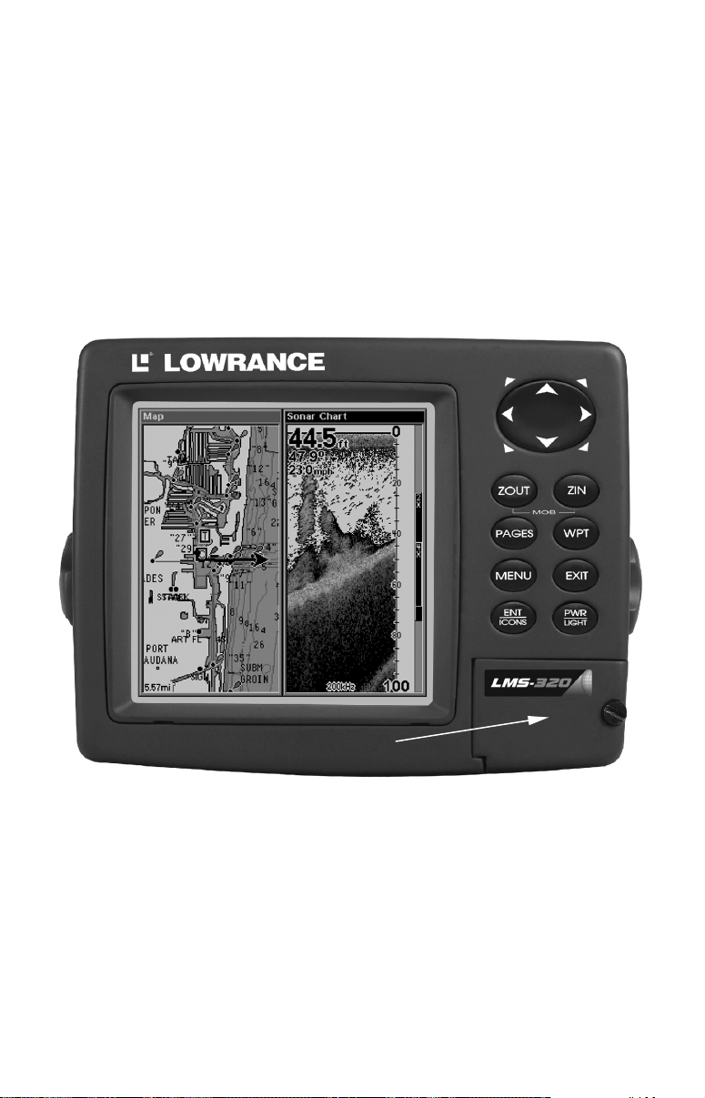
Section 3: Basic Sonar Operation
This section addresses the unit's most basic sonar operations. The instructions presented in Sec. 3 follow a chronological order. Sec. 4, Sonar
Options & Other Features, will discuss other more advanced functions
and utilities. Material in Sec. 4 is arranged in alphabetical order.
Before you turn on the LMS-320, it's a good idea to learn about the different keys, the Main Menu, the four Page screens and how they all
work together. BUT, if you just can't wait to get on the water, turn to
the one-page Quick Reference on page 49.
Keyboard
4
8
2
3
5
MMC slot access door
LMS-320 series sonar/GPS unit, front view, showing map with sonar
split screen, keyboard and access door for the MMC slot.
9
7
6
1
1. PWR/LIGHT (Power & Light) – The PWR key turns the unit on and
off and activates the backlight.
2. PAGES – Pressing this and the ← → arrow keys switches the unit
between the four different page screens. (Satellite Status Page, Navigation Page, Map Page and Sonar Page.) Each page represents one of the
unit's major operation modes.
41
Page 50

3. MENU – Press this key to show the menus and submenus, which
allow you to select a command or adjust a feature. This also accesses
search functions for streets, intersections, addresses and highway exits.
4. ARROW KEYS – These keys are used to navigate through the
menus, make menu selections, move the map and sonar chart cursors
and enter data.
5. ENT/ICONS (Enter & Icons) – This key allows you to save data, accept values or execute menu commands. It is also used to create event
marker icons.
6. EXIT – The Exit key lets you return to the previous screen, clear
data or erase a menu.
7. WPT – (Waypoint) The Waypoint key is used to save and recall waypoints, search for waypoints and access the waypoint list. It also
launches the Point-of-Interest (POI) search menus and is involved in
some navigation functions.
8. ZOUT – (Zoom Out) – This key lets you zoom the screen out. On the
Sonar Page, this key returns you to a full sonar chart display, showing
the entire water column from surface to bottom. On the Map Page, this
lets you see a larger geographic area on the map. Less detail is seen as
you zoom out.
9. ZIN – (Zoom In) – This key lets you zoom the screen in. On the Sonar
Page, this key enlarges fish signals and bottom detail. On the Map
Page, zooming in lets you see greater detail in a smaller geographic
area on the map.
Power/lights on and off
To turn on the unit, press
displayed first. To switch to the Sonar Page, press
To turn on the backlight, press
levels to select from. Repeatedly pressing
backlight settings and turn off the backlight.
Turn off the unit by pressing and holding the
. As the unit powers up, the Map Page is
PWR
PAGES
again. The unit has three backlight
PWR
will cycle through the
PWR
key for 3 seconds.
PWR
|→|
EXIT
.
Main Menu
The LMS-320 has a Main Menu, which contains some function commands and some setup option commands. The instructions in this section will deal only with sonar functions, the basic commands that make
LMS-320 show sonar signals on your screen. LMS-320 will work fine
right out of the box with the factory default settings. But, if you want to
42
Page 51
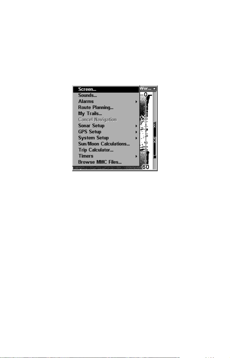
learn about the various sonar options, see Sec. 4, Sonar Options &
Other Features. (For general system setup and GPS options, see Sec. 8,
System Setup and GPS Setup Options.)
You can access the Main Menu from any of the four Page screens by
pressing
MENU|MENU
display, press
EXIT
. To clear the menu screen and return to the page
. (Remember, our text style for "
MENU|MENU
" means
"press the Menu key twice." See a full explanation of our instruction
text formatting on page 10, Instructions = Menu Sequences.)
Main Menu.
The Main Menu commands and their functions are:
Screen command: changes the contrast or brightness of the display
screen.
Sounds command: enables or disables the sounds for key strokes and
alarms and sets the alarm style.
Alarms command: turns GPS alarms on or off and changes alarm
thresholds.
Route Planning command: used to plan, view or navigate a route.
My Trails command: shows, creates and deletes plot trails. Also used
to navigate or backtrack a trail.
Cancel Navigation command: turns off the various navigation commands. Used to stop navigating after you have reached your destination waypoint, Point of Interest or map cursor location; or after you
reach the end of a route or trail.
Sonar Setup command: sets various sonar options.
GPS Setup command: sets various GPS receiver options.
43
Page 52
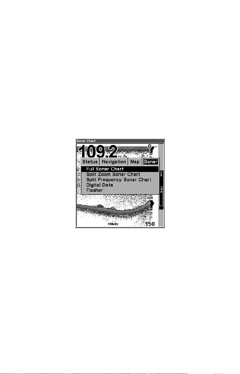
System Setup command: sets general configuration options.
Sun/Moon Calculations command: finds the rising and setting time
of the sun and the moon.
Trip Calculator command: shows trip status and statistics.
Timers command: controls the up timer, down timer and alarm clock
settings.
Browse MMC Files command: this allows you to view the installed
MMC card and the files it contains.
Pages
The unit has four Page displays that represent the four major operating
modes. They are the Satellite Status Page, the Navigation Page, the Map
Page and Sonar Page. They are accessed by pressing the
PAGES
then using → or ← to select a Page. (Clear the Pages Menu by pressing
.)
EXIT
key,
Pages Menu, showing some Sonar display options.
Satellite Status Page
The Satellite Status Page provides detailed information on the status of
LMS-320's satellite lock-on and position acquisition. To get to the Satellite Status Page: Press the
. (Clear the Pages Menu by pressing
S
TATUS
PAGES
key, then use → or ← to select
.)
EXIT
This page represents a GPS function, so it is discussed in much greater
detail in Sec. 6.
No matter what Page you are on, a flashing current position indicator/question mark symbol and flashing GPS data displays indicate that
satellite lock has been lost and there is no position confirmed.
WARNING:
Do not begin navigating with this unit until the numbers
have stopped flashing!
44
Page 53
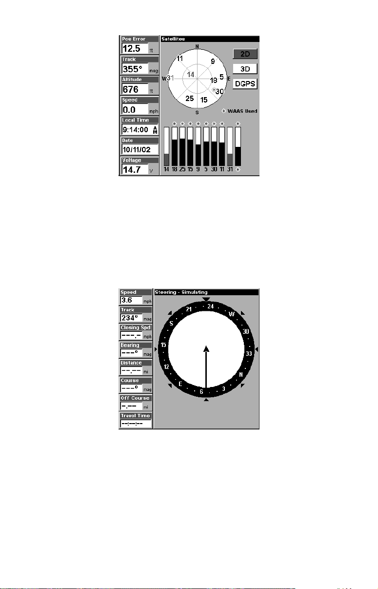
Satellite Status Page showing satellite lock-on with a 3D position
acquired (latitude, longitude and altitude), including WAAS reception.
Navigation Page
This screen has a compass rose that not only shows your direction of
travel, but also the direction to a recalled waypoint. To get to the Navigation Page: Press
PAGES
| → or ← to
N
AVIGATION
|
EXIT
.
This page represents a GPS function, so it is discussed in much greater
detail in Sec. 6.
Navigation Page, recording a trail, traveling southwest.
Map Page
The Map Page screens show your course and track from a "bird's-eye"
view, on a moving map. By default, this unit shows the map with north
always at the top of the screen. The arrow in the center of the screen is
your present position. It points in the direction you're traveling.
45
Page 54
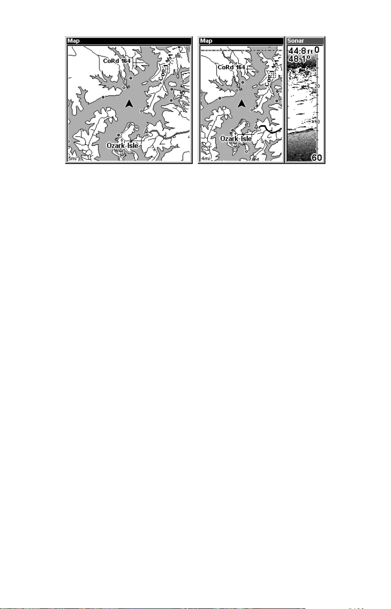
Map Page, showing position on Bull Shoals Lake, Arkansas. At left is
the full map option. At right, map with sonar option.
Map Page is also the default screen that appears when you turn on the
unit. To get to the Map Page from another page: Press
to
|
EXIT
.
M
AP
PAGES
| → or ←
You can display a split screen showing both the Map and Sonar pages
at the same time. This feature is discussed in Sec. 4, Sonar Options &
Other Features.
The Map Page represents a GPS function, so it is discussed in much
greater detail in Sec. 6.
Sonar Page
The Sonar Page displays the sonar chart. This is a "cross-section" view
of the water column beneath the boat. The chart moves across the
screen, displaying sonar signal echoes that represent fish, structure
and the bottom.
To get to the Sonar Page: Press the
lect
. (Clear the Pages Menu by pressing
S
ONAR
PAGES
key, then use → or ← to se-
.) The Pages Menu
EXIT
also offers five chart display options under the Sonar Page category. To
access them, press
PAGES
|← or→ to
|↓ to Option Name|
S
ONAR
EXIT
.
The Sonar Page also has its own menu, which is used for some advanced
functions and for setting various options. (Sonar Options and other features are discussed in Sec. 4.) To Access the Sonar Page menu, from the
Sonar Page press
MENU
.
46
Page 55
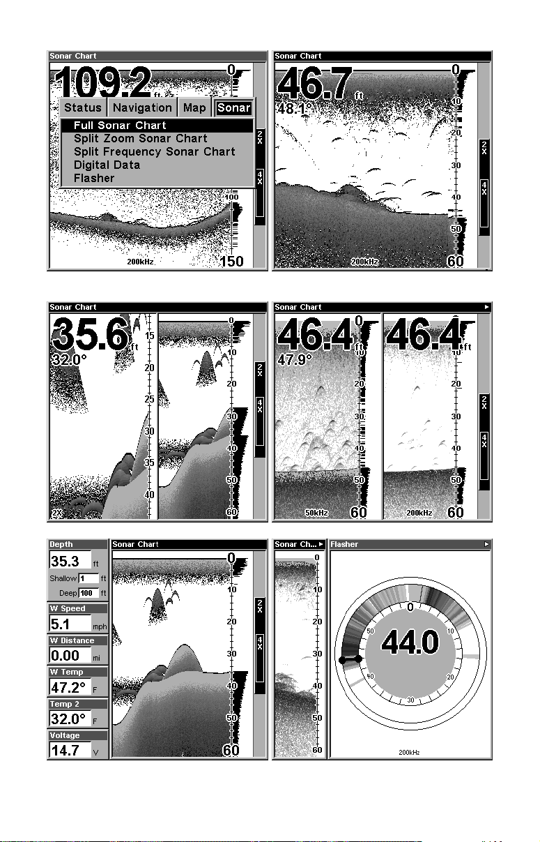
At left, Pages Menu, showing sonar chart display option commands.
At right, Sonar Page in full sonar chart display mode.
Sonar chart display options (from left) split zoom and split frequency.
Sonar chart display options (from left) digital data and flasher.
47
Page 56
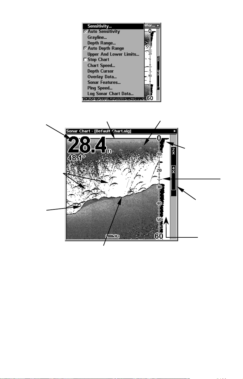
Sonar Page Menu. Most of these functions are discussed in Sec. 4.
Digital data
overlay
(depth &
temperature)
Fish arches
Structure
Surface signal
Bottom signal
Sonar Page, showing full sonar chart mode.
Surface clutter
Depth scale
In FasTrack, fish
arches show as
horizontal bars.
Zoom bar
FasTrack
bar graph
You can customize how the Sonar Page displays its pictures and other
data in many ways. Your unit also includes several special sonar features and options that can help you better interpret the underwater
scene.
We'll discuss all of those features and options in Sec. 4, but to show you
how easy the LMS-320 is to operate, the following page contains a simplified, 10-step quick reference that will cover most fish finding situations. The quick reference describes how your unit will operate with all
the sonar features in their automatic modes, which are set at the factory.
48
Page 57

LMS-320 Series Sonar Quick Reference
1. Mount the transducer, antenna and unit. Connect the unit to electric
power and the transducer. (If GPS operation is desired, connect GPS
antenna, too.) Make sure the MMC is in. (See complete installation details beginning on page 13.)
2. Launch your boat.
3. To turn on LMS-320, press and release
PWR
key.
4. Opening screen displays Map Page. Rotate through the four main
Page screens (Map Page, Satellite Status Page, Navigation Page, Sonar
Page) by pressing
PAGES
|← or → to select Page Name|
EXIT
. Switch
Pages to display Sonar Page.
5. If GPS data is desired, wait while unit locates satellites and calculates
current position. When the unit acquires position, a tone sounds and a position acquired message appears.
6. With position acquired (if desired), head for your fishing grounds.
Your unit will automatically display digital depth and surface water
temperature in the top left corner of the screen.
The auto settings will track the bottom, displaying it in the lower portion of the screen. The full sonar chart will scroll from right to left,
showing you what's under the boat as you cruise across the water. You
can change the display by:
Zoom in to enlarge the chart for more detail: press
Zoom out to return to full chart mode: press
ZOUT
.
ZIN
.
7. Watch the display for the appearance of fish arches. When you see
arches, you've found fish! Stop the boat and get your lure or bait into
the water at the depth indicated on the sonar chart.
8. Gauge the fish depth by visually comparing the fish arches with the
depth scale on the right side of the screen, or get a more accurate
measure with the Depth Cursor. Press
MENU
|↓ to
D
EPTH CURSOR
|
ENT
Press ↓ to align the cursor line with the fish arch. The exact depth appears in a box at the right end of the cursor line. To clear the cursor,
press
EXIT
.
.
9. If you are drifting at a very low speed or anchored, you are not moving fast enough for a fish to return the tell-tale fish arch signal. As you
drift over a fish, or as a fish swims through the transducer's signal
cone, the fish echo will appear as a straight line suspended between the
surface and the bottom.
10. To turn off LMS-320, press and hold
key for three seconds.
PWR
49
Page 58
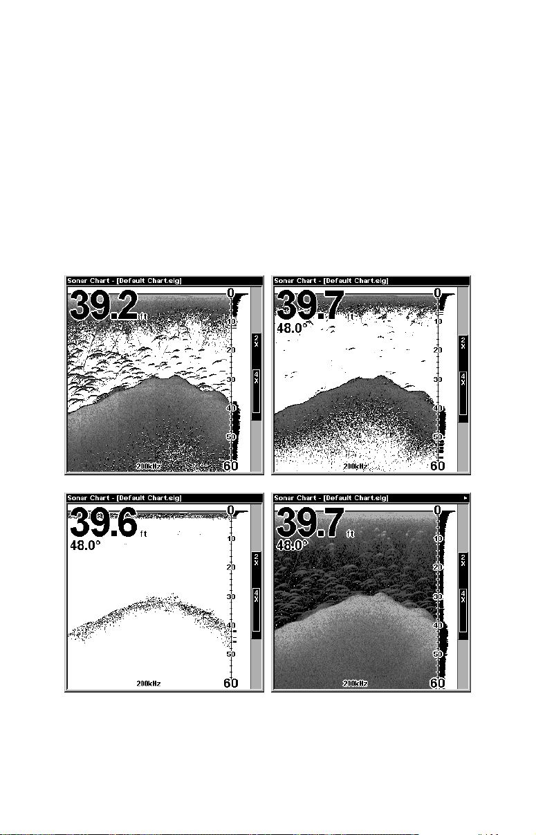
Sonar Operations
As you can see from the quick reference on the previous page, basic operation
is pretty easy, right out of the box. If you are a sonar novice, try operating the
unit with the factory defaults until you get a feel for how it's working.
As you're learning the basics, there is one setting you might want to tinker
with from time to time — Sensitivity.
Sensitivity controls the unit's ability to pick up echoes. If you want to see
more detail, try increasing the sensitivity, a little at a time. There are situations when too much clutter appears on the screen. Decreasing the sensitivity
can reduce the clutter and show the strongest fish echoes, if fish are present.
As you change the sensitivity setting, you can see the difference on the chart
as it scrolls.
Fig. 1
Fig. 2
Fig. 3
Fig. 4
These figures show results of different sensitivity levels on the same
location. Fig. 1: Sensitivity at 88 percent, determined by Auto Sensitiv-
ity. Typical of full auto mode. Fig. 2: Sensitivity set at 75 percent. Fig.
3: Sensitivity set at 50 percent. Fig. 4: Sensitivity set at 100 percent.
50
Page 59
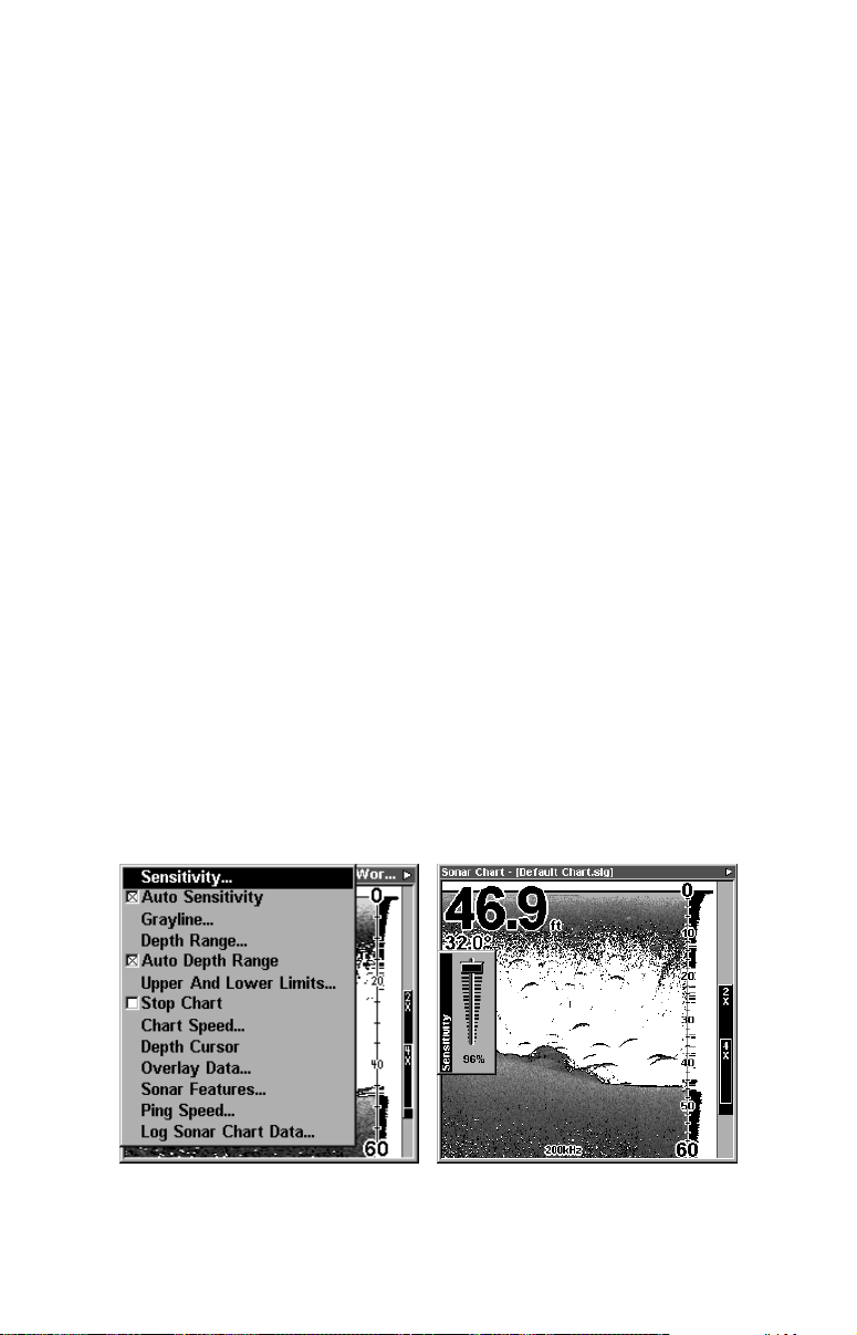
You can change the sensitivity level whether you are in Auto Sensitivity mode or Manual Sensitivity mode. The adjustment method works
the same in both modes, but it gives you slightly different results.
Adjusting sensitivity in Auto Sensitivity Mode is similar to manually adjusting a car's speed with the accelerator pedal while cruise control is on.
You can tell the car to run faster, but when you let off the gas the cruise
control automatically keeps you from running slower than the minimum
speed setting. In the LMS-320, auto mode will let you increase sensitivity
to 100 percent, but the unit will limit your minimum setting. This prevents you from turning sensitivity down too low to allow automatic bottom tracking. When you change the setting with auto turned on, the unit
will continue to track the bottom and make minor adjustments to the sensitivity level, with a bias toward the setting you selected.
Adjusting sensitivity in Manual Sensitivity Mode is similar to driving a
car without cruise control — you have complete manual control of the
car's speed. In the LMS-320, manual mode allows you to set sensitivity
at 100 percent (maximum) or zero percent (minimum.) Depending on
water conditions, the bottom signal may completely disappear from the
screen when you reduce sensitivity to about 50 percent or less!
Try adjusting sensitivity in both auto and manual modes to see how
they work.
To adjust sensitivity:
1. Press
MENU|ENT
.
2. The Sensitivity Control Bar appears. Press ↓ to decrease sensitivity;
press ↑ to increase sensitivity. When it's set at the desired level, press
. (When you reach the maximum or minimum limit, a tone sounds.)
EXIT
At left, Sonar Menu with Sensitivity command selected. At right, the
Sensitivity Control Bar.
51
Page 60

NOTE:
If you want to change the sensitivity in Manual Mode, first turn off
|↓ to
Auto Sensitivity: from the Sonar Page, press
|
S
ENSITIVITY
ENT
|↑ to
S
ENSITIVITY
|
. Press ↓ or ↑ to pick a different
ENT
MENU
sensitivity setting. When it's set at the desired level, press
EXIT
A
UTO
.
Important Tip:
While you are experimenting and learning, it's possible to scramble
the settings so that the sonar picture disappears from your screen.
If that happens, remember that it's easy to switch back to full
automatic operation by simply restoring the factory auto settings.
Here's how:
To Restore Factory Settings
1. Press
TIONS
MENU|MENU
|
.
ENT
2. The unit asks if you want to reset all the options. Press ← to
|
Y
ES
. All options are reset, and the unit reverts back to the Map
ENT
Page at the 4000 mile zoom range. (Any recorded sonar logs or GPS
data will be unchanged.)
Fish Symbols vs. Full Sonar Chart
You may have noticed in the quick reference that we used fish arches in
full sonar chart mode for our example, and not the popular Fish I.D.
fish symbol feature. Here's why.
Fish I.D. is an easier way for a sonar novice to recognize a fishy signal
return when he sees it. However, locating fish by symbol only has some
limitations.
Your sonar unit's microprocessor is remarkably powerful, but it can be
fooled. Some of the echoes calculated to be fish could be tree limbs or
turtles! To see what's under your boat in maximum detail, we recom-
mend you turn off Fish I.D. and begin learning to interpret fish arches.
Fish I.D. is most handy when you're in another part of the boat or performing some task that prevents you from watching the sonar screen.
Then, you can turn on Fish I.D. and the audible fish alarm. When that
lunker swims under your boat, you'll hear it!
Fish I.D. can also be useful when you want to screen out some of the
sonar detail gathered by your unit. For example, in one case fisherman
in San Francisco Bay saw clouds of clutter in the water but no fish
arches. When a down rigger was pulled up, it brought up several small
jellyfish. The fisherman switched their Lowrance sonar to Fish I.D.,
which screened out the schools of jellyfish and clearly showed the game
fish there as fish symbols.
|↓ to
S
YSTEM SETUP
|
ENT
|↓ to
R
ESET OP-
52
Page 61

Other Free Training Aids
The sonar options section discusses Fish I.D., fish alarms and other
features in greater detail. If you or a friend has Internet access, you can
also learn more about interpreting what you see on your sonar screen.
Visit our web site,
WWW.LOWRANCE.COM
. Be sure to check out the free
Sonar Tutorial, which includes animated illustrations and more pictures of actual sonar returns, all described in detail. There's even a
"printer friendly" version of the tutorial available on our web site…it
makes a great supplement to this operation manual!
You can also download a free copy of our Sonar Viewer software. This
PC-based software application plays back any sonar chart log recorded
with a Lowrance sonar product. Features include:
• Adjustable range, zoom, sensitivity, color line, noise rejection,
surface clarity, etc. of the recorded file.
• Color interpretation of sonar signals can be user defined.
• Operates like a Windows Multimedia Player with forward, re-
verse, pause, fast forward, fast reverse, and scroll buttons.
• Adjustments update the entire record displayed
• Can print in full color.
• Window can dynamically be sized on your monitor.
• Mouse cursor shows GPS position, depth and sounding number
anywhere on the visible record.
For the ultimate training aid, be sure to download the free emulator
software for your unit. Aside from being just plain fun, this program
can help you learn both basic and advanced operations without burning
boat fuel! Lowrance is the first sonar manufacturer to provide this type
of training tool for customers.
This PC application simulates the actual sonar/GPS unit on your computer. You can run it from your computer keyboard or use your mouse
to press the virtual keys. Easy download and installation instructions
are available on our web site.
53
Page 62
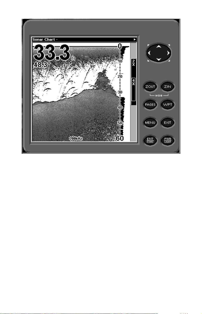
Free training emulator is available for your unit on our web site.
The emulator works exactly like your real sonar/GPS unit. Using the
Sonar Simulator and GPS Simulator features, it allows you to play
back sonar logs, run GPS routes and trails, even create real waypoints
you can use in the field! You can even take snapshots of the Sonar
Chart and print them or e-mail them to friends.
54
Page 63
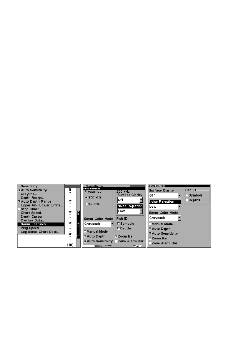
Section 4: Sonar Options & Other Features
Material in this section is arranged in alphabetical order.
ASP (Advanced Signal Processing)
The ASP feature is a noise rejection system built into the sonar unit
that constantly evaluates the effects of boat speed, water conditions
and interference. This automatic feature gives you the best display possible under most conditions.
The ASP feature is an effective tool in combating noise. In sonar terms,
noise is any undesired signal. It is caused by electrical and mechanical
sources such as bilge pumps, engine ignition systems and wiring, air
bubbles passing over the face of the transducer, even vibration from the
engine. In all cases, noise can produce unwanted marks on the display.
The ASP feature has four settings — Off, Low, Medium and High. If
you have high noise levels, try using the "High" ASP setting. However,
if you are having trouble with noise, we suggest that you take steps to
find the interference source and fix it, rather than continually using the
unit with the high ASP setting.
There are times when you may want to turn the ASP feature off. This
allows you to view all incoming echoes before they are processed by the
ASP feature.
At left, Sonar Menu with Sonar Features selected. In the Sonar
Features menu, Noise Rejection is selected with ASP in the default low
setting (center, dual-frequency menu; at right, single-frequency menu).
To change the ASP level:
1. From the Sonar Page, press
2. Press → ↓
or ↓ to
N
OISE REJECTION
3. Press ↓ or ↑ to select a setting, then press
4. To return to the previous page, press
MENU
|
|↓ to
ENT
S
ONAR FEATURES
.
ENT
EXIT|EXIT
|
.
ENT
.
.
55
Page 64
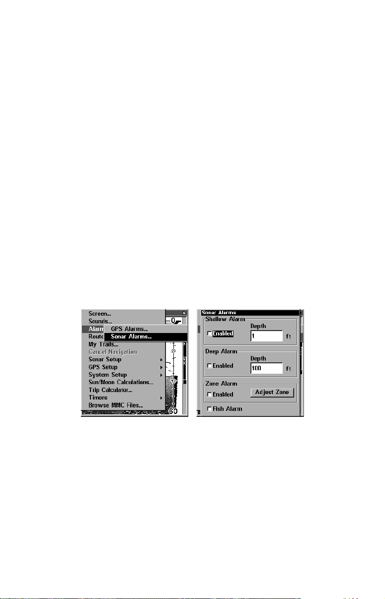
Alarms
This unit has three different types of sonar alarms. The first is the Fish
Alarm. It sounds when the Fish I.D. feature determines that an echo
is a fish.
Another alarm is the Zone Alarm, which consists of a bar on the side of
the screen. Any echo on the chart that appears inside this bar triggers
this alarm.
The last alarm is the Depth Alarm, which has both a Shallow and a
Deep setting. Only the bottom signal will trigger this alarm. This is
useful as an anchor watch, a shallow water alert or for navigation.
Depth Alarms
The depth alarms sound a tone when the bottom signal goes shallower
than the shallow alarm's setting or deeper than the deep alarm's setting. For example, if you set the shallow alarm to 10 feet, the alarm will
sound a tone if the bottom signal is less than 10 feet. It will continue to
sound until the bottom goes deeper than 10 feet.
The deep alarm works just the opposite. It sounds a warning tone if the
bottom depth goes deeper than the alarm's setting. Both depth alarms
work only off the digital bottom depth signals. No other targets will trip
these alarms. These alarms can be used at the same time or individually.
At left, Main Menu and Sonar Alarms command.
At right, the Sonar Alarms menu.
To adjust and turn on the shallow alarm:
1. Press
MENU|MENU
2. Press → to
S
|↓ to
A
LARMS
HALLOW ALARM DEPTH
|
|
ENT
ENT
|↓ to
.
S
ONAR ALARMS
|
ENT
.
3. Press ↑ or ↓ to change the first number, then press → to move the
cursor to the next number and repeat until the depth is correct, then
press
ENT
.
56
Page 65
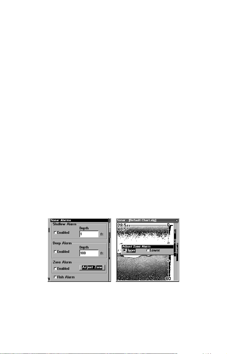
4. Press ← to
S
HALLOW ALARM ENABLED
|
ENT|EXIT|EXIT|EXIT
.
5. To turn off the alarm, press
S
ONAR ALARMS
|
ENT|ENT|EXIT|EXIT|EXIT
MENU|MENU
.
|↓ to
A
LARMS
|
ENT
|↓ to
To switch to a different depth setting, open the Sonar Alarms menu and
repeat the instructions in step 3 above.
To adjust and turn on the deep alarm:
1. Press
MENU|MENU
2. Press ↓ to
D
EEP ALARM ENABLED
|↓ to
A
LARMS
|
ENT
|→ to
|↓ to
S
ONAR ALARMS
D
EEP ALARM DEPTH
|
|
ENT
ENT
.
.
3. Press ↑ or ↓ to change the first number, then press → to move the
cursor to the next number and repeat until the depth is correct, then
press
4. Press ← to
5. To turn off the alarm, press
S
ONAR ALARMS
ENT
.
D
EEP ALARM ENABLED
|
|↓ to
ENT
|
ENT|EXIT|EXIT|EXIT
MENU|MENU
D
EEP ALARM ENABLED
.
|↓ to
|
ENT|EXIT|EXIT|EXIT
A
LARMS
|
ENT
|↓ to
.
To switch to a different depth setting, open the Sonar Alarms menu and
repeat the instructions in step 3 above.
Zone Alarm
The zone alarm is triggered when any echo passes inside the zone
alarm bar, shown on the right side of the screen.
To adjust and turn on the zone alarm:
1. Press
MENU|MENU
|↓ to
A
LARMS
|
ENT
|↓ to
S
ONAR ALARMS
|
ENT
.
2. Press ↓ to
Z
ONE ALARM ENABLED
|→ to
A
DJUST ZONE
|
ENT
.
At left, Sonar Alarms menu, with Adjust Zone command selected.
At right, Adjust Zone Alarm selection box, with Upper selected.
3. To set the upper boundary for the Zone Alarm, use ← or→ to select
, then press ↑ or ↓ to move the top of the bar to the desired depth.
U
PPER
4. To set the lower boundary for the Zone Alarm, use ← or→ to select
57
Page 66
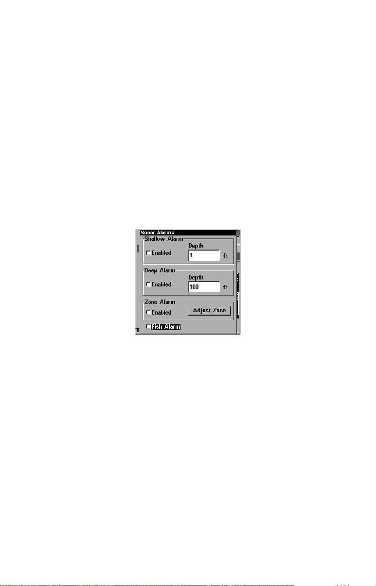
, then press ↑ or ↓ to move the bottom of the bar to the desired
L
OWER
depth.
5. Press
EXIT
|← to
Z
ONE ALARM ENABLED
|
ENT|EXIT|EXIT|EXIT
. Now, any
echo — fish, bottom, structure — within the zone alarm's depth range
will trigger the zone alarm.
6. To turn off the alarm, press
|
S
ONAR ALARMS
ENT
|↓ to
Z
ONE ALARM ENABLED
MENU|MENU
|↓ to
|
ENT|EXIT|EXIT|EXIT
A
LARMS
|
ENT
|↓ to
.
To switch to a different depth setting, open the Sonar Alarms menu and
repeat the instructions in steps 3 and 4 above.
Fish Alarm
Use the fish alarm for a distinctive audible alarm when fish or other
suspended objects are detected by the Fish I.D. feature (Fish I.D.
must be turned on for the Fish Alarm to work). A different tone sounds
for each fish symbol size shown on the display.
Sonar Alarms menu with Fish Alarm selected. The check box to the left
is blank, indicating the alarm is turned off.
To turn the fish alarm on:
1. Press
2. Press ↓ to
MENU|MENU
F
ISH ALARM
3. To turn off the alarm, press
S
ONAR ALARMS
|
ENT
|↓ to
A
LARMS
|
ENT|EXIT|EXIT|EXIT
|↓ to
F
ISH ALARM
|
|↓ to
ENT
S
ONAR ALARMS
.
MENU|MENU
|
ENT|EXIT|EXIT|EXIT
|↓ to
A
LARMS
.
|
ENT
|
.
ENT
|↓ to
Calibrate Speed
The speed sensor can be calibrated to compensate for inaccuracies. Before you change the setting, first calculate the percentage that the
speed is off. You will enter this percentage in a moment.
For example, if you figure the sensor is reading 10 percent faster than
actual speed, you will enter – 10 in the calibration window. If the sensor is reading 5 percent slower than true speed, you will enter + 5 in
the window.
58
Page 67
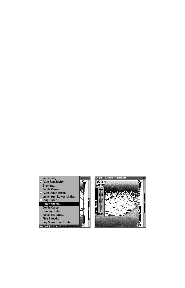
A good way to gauge your speed sensor's performance is to compare its
reading with the ground speed measured by your unit's GPS functions.
When you make a run to compare GPS ground speed to speed sensor
speed, perform your test in relatively calm water free of current, if possible. (Unless, of course, you are taking the current speed into consideration when making your calculation.) After you have a correction figure, here's how to enter it:
1. Press
|
S
PEED
ENT
MENU|MENU
.
|↓ to
S
ONAR SETUP
|
ENT
|↓ to
C
ALIBRATE WATER
2. Enter the number you calculated earlier: press ↑ or ↓ to change the
first character (+ or –), then press → to move the cursor to the next
number and repeat until the percentage is correct, then press
EXIT
.
Chart Speed
The rate that echoes scroll across the screen is called the chart speed.
The default is maximum; we recommend that you leave the speed set
there for virtually all fishing conditions.
However, you might consider experimenting with chart speed when you
are stationary or drifting very slowly. You may sometimes achieve better images as you slow down the chart speed to match how fast you are
moving across the bottom.
If you are at anchor, ice fishing or fishing from a dock, experiment with
a chart speed around 50 percent. If you are drifting slowly, try a chart
speed around 75 percent. When you are stationary and a fish swims
through the sonar signal cone, the image appears on the screen as a
long line instead of a fish arch. Reducing the chart speed may result in
a shorter line that more closely resembles a regular fish return.
At left, Sonar Page menu with Chart Speed command selected.
At right, Chart Speed Control Bar.
If you do experiment with chart speed, remember to reset it to maximum when you resume trolling or moving across the water at higher
speed. To change chart speed:
59
Page 68
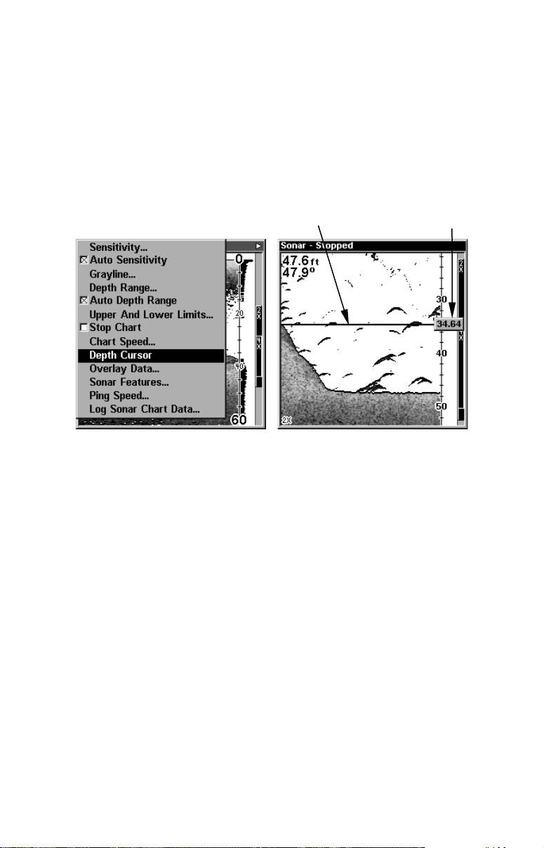
1. From the Sonar Page, press
MENU
|↓ to
C
HART SPEED
|
ENT
.
2. The Chart Speed Control Bar appears. Press ↓ to decrease chart
speed; press ↑ to increase chart speed.
3. When it's set at the desired level, press
EXIT
.
Depth Cursor
The depth cursor consists of a horizontal line with a digital depth box
on the right side. The numbers inside the box show the depth of the
cursor.
At left, Sonar Page menu with Depth Cursor command selected. At
right, sonar chart with the depth cursor active. The line indicates the
large fish is 34.64 feet deep.
The cursor can be moved to any location on the screen, letting you pinpoint the depth of a target.
Cursor line
Depth box
1. From the Sonar Page, press
MENU
|↓ to
D
EPTH CURSOR
|
ENT
.
2. The depth cursor appears. Press ↓ to lower the cursor line; press ↑ to
raise the cursor line.
3. To clear the depth cursor, press
EXIT
.
Depth Range - Automatic
When turned on for the first time, the bottom signal is automatically
placed in the lower half of the screen. This is called Auto Ranging and
is part of the automatic function. However, depending upon the bottom
depth and the current range, you can change the range to a different
depth. To do this:
1. From the Sonar Page, press
MENU
|↓ to
60
D
EPTH RANGE
|
ENT
.
Page 69
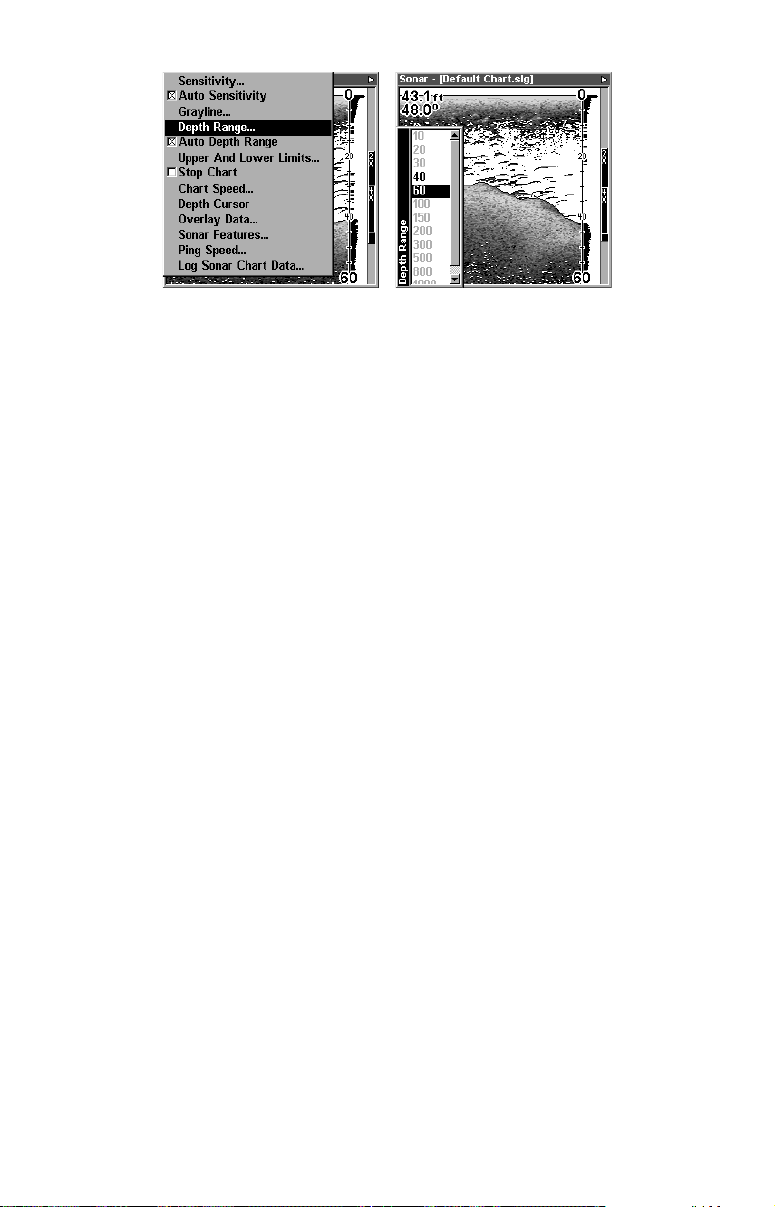
At left, Sonar Page menu with Depth Range command selected. At
right, the Depth Range Control Scale.
2. The Depth Range Control Scale appears. Press ↑ or ↓ to select a different depth range. A black bar highlights the selected range. Range
numbers in gray cannot be selected.
3. When the new range is selected, press
to clear the menu.
EXIT
Depth Range - Manual
You have complete control over the range when the unit is in the manual mode. There are 16 depth ranges, from 5 feet to 4,000 feet.
To switch to Manual Depth Range:
1. First, turn off automatic depth range. From the Sonar Page, press
|↓ to
MENU
2. Press ↑ to
A
UTO DEPTH RANGE
D
EPTH RANGE
3. Press ↓ or ↑ to select a different depth range. A horizontal black bar
highlights the selected range.
4. When the new range is selected, press
To turn Auto Depth Range on again:
1. From the Sonar Page, press
NOTE:
The sonar's depth capability depends on the transducer installation, water and bottom conditions, and other factors.
|
.
ENT
|
and the Depth Range Control Scale appears.
ENT
to clear the menu.
EXIT
MENU
|↓ to
A
UTO DEPTH RANGE
|
ENT|EXIT
.
Depth Range - Upper and Lower Limits
Virtually any segment of the water column can be displayed by using
the upper and lower limit feature. This lets you pick the shallow and
deep depth range limits that are shown on the screen, provided there is
at least 10 feet between the upper and lower limit you select. For example, a range from 12 feet to 34 feet could be used.
Changing the upper and lower limits gives you far greater control over
the depth range. This feature lets you "zoom in" the display in almost
unlimited combinations. Nearly any segment of the water column, from
61
Page 70
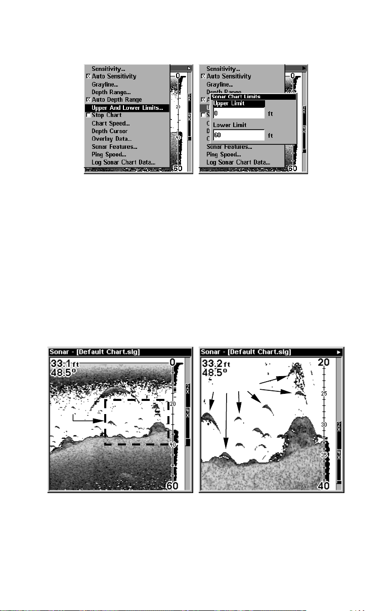
the surface to the bottom can be shown. This enlarges the sonar targets
to best suit your fishing needs and water conditions.
At left, Sonar Page Menu with Upper and Lower Limits command se-
lected. At right, Sonar Chart Limits menu, with Upper Limit selected.
To change the upper and lower limits:
1. From the Sonar Page, press
MENU
|↓ to
U
PPER AND LOWER LIMITS
|
ENT
The Sonar Chart Limits menu appears, with Upper Limit selected.
.
2. To set the upper limit, press
. Press ↑ or ↓ to change the first
ENT
number, then press → to move the cursor to the next number and repeat until the depth is correct, then press
3. To set the lower limit, press ↓ to
L
OWER LIMIT
EXIT
.
|
. Press ↑ or ↓ to
ENT
change the first number, then press → to move the cursor to the next
number and repeat until the depth is correct, then press
EXIT|EXIT|EXIT
Area "zoomed"
.
Fish arches
Normal display, in auto depth range mode, left. At right, display
"zoomed" with Upper and Lower Limits focusing on the portion of the
water column from 20 feet to 40 feet deep. In the "zoomed" image, note
the target definition at lower left, showing a fish holding just above the
structure. At top right, two game fish are attacking a school of bait fish.
62
Page 71
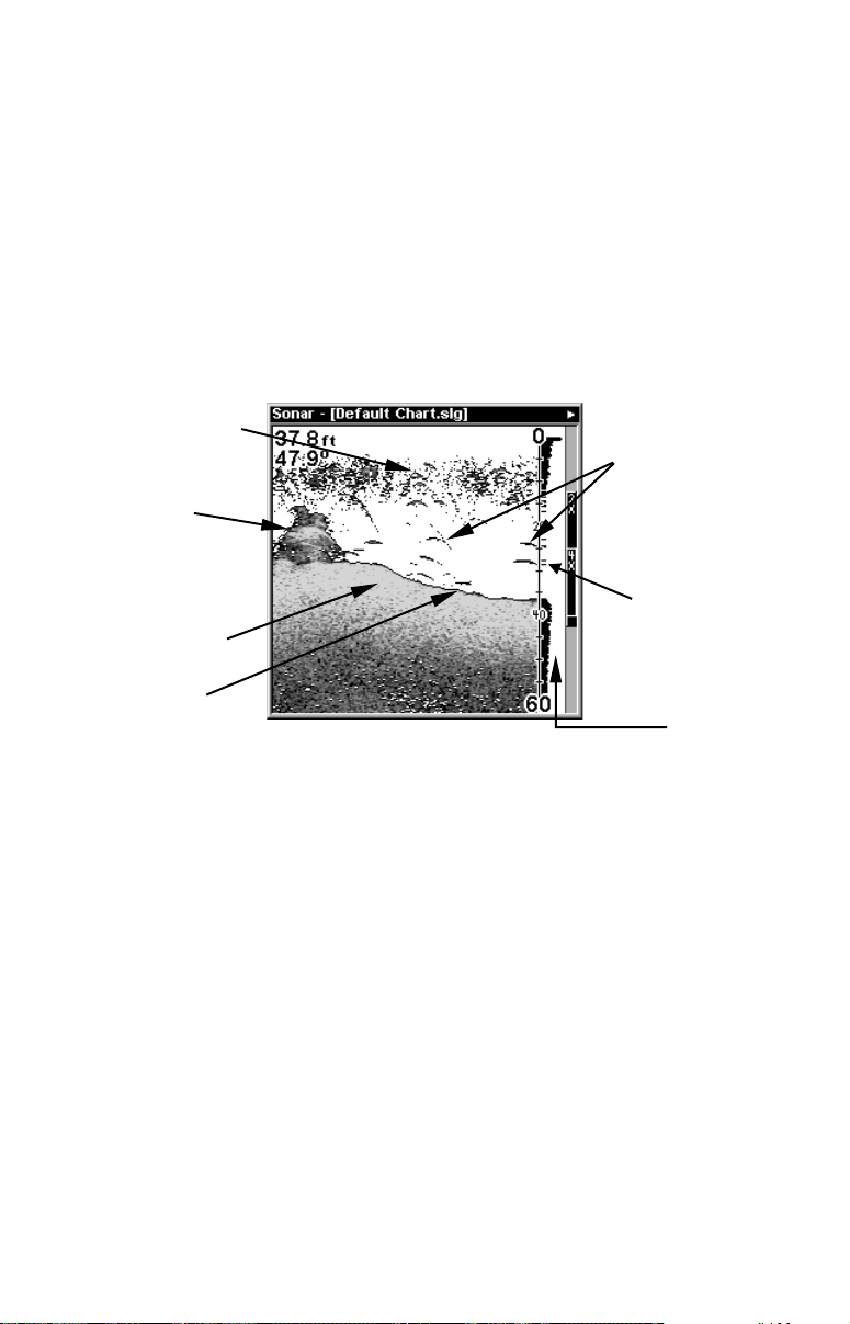
To turn off upper and lower limits:
From the Sonar Page, press
MENU
|↓ to
A
UTO DEPTH RANGE
|
ENT|EXIT
.
FasTrack
This feature automatically converts all echoes to short horizontal lines
on the display's far right side. The graph on the rest of the screen continues to operate normally. FasTrack gives you a rapid update of conditions directly under the boat. This makes it useful for ice fishing, or
when you're fishing at anchor. When the boat is not moving, fish signals are long, drawn out lines on a normal chart display. FasTrack converts the graph to a vertical bar graph that, with practice, makes a useful addition to fishing at a stationary location.
Surface clutter
Fish arches
Structure
In FasTrack, fish
arches show as
Grayline
horizontal bars.
Bottom signal
Sonar Page showing FasTrack.
FasTrack
bar graph
Fish I.D. (Fish Symbols & Depths)
The Fish I.D. feature identifies targets that meet certain conditions as
fish. The microcomputer analyzes all echoes and eliminates surface
clutter, thermoclines, and other signals that are undesirable. In most
instances, remaining targets are fish. The Fish I.D. feature displays
fish symbols on the screen in place of the actual fish echoes.
There are several fish symbol sizes. These are used to designate the
relative size between targets. In other words, Fish I.D. displays a small
fish symbol when it thinks a target is a small fish, a medium fish symbol on a larger target and so on.
The sonar's microcomputer is sophisticated, but it can be fooled. It can't
distinguish between fish and other suspended objects such as trotlines,
turtles, submerged floats, air bubbles, etc. Individual tree limbs extending outwards from a group of limbs is the hardest object for the
Fish I.D. feature to distinguish from fish.
63
Page 72
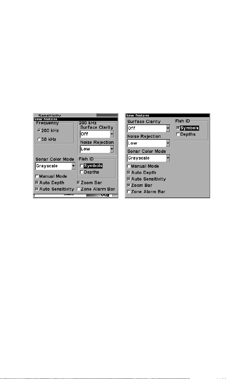
You may see fish symbols on the screen when actually, there are no
fish. The reverse is also true. The illustrations on the next page show
how Fish I.D. can actually miss fish that are present.
Does that mean Fish I.D. is broken? No — the feature is simply interpreting sonar returns in a specific way to help take some of the work
out of reading the screen. Remember: Fish I.D. is one of the many tools
we provide so you can analyze your sonar returns for maximum fish
finding information. This and other features can help you successfully
"see" beneath the boat under varied water and fishing conditions. So,
practice with the unit in both the Fish I.D. mode and without to become
more familiar with the feature. The default for Fish I.D. is off.
Sonar Features menu with Fish I.D. Symbols selected (at left, dual-
frequency menu; at right, single-frequency menu). When the check box
to the left is checked, the feature is on.
64
Page 73
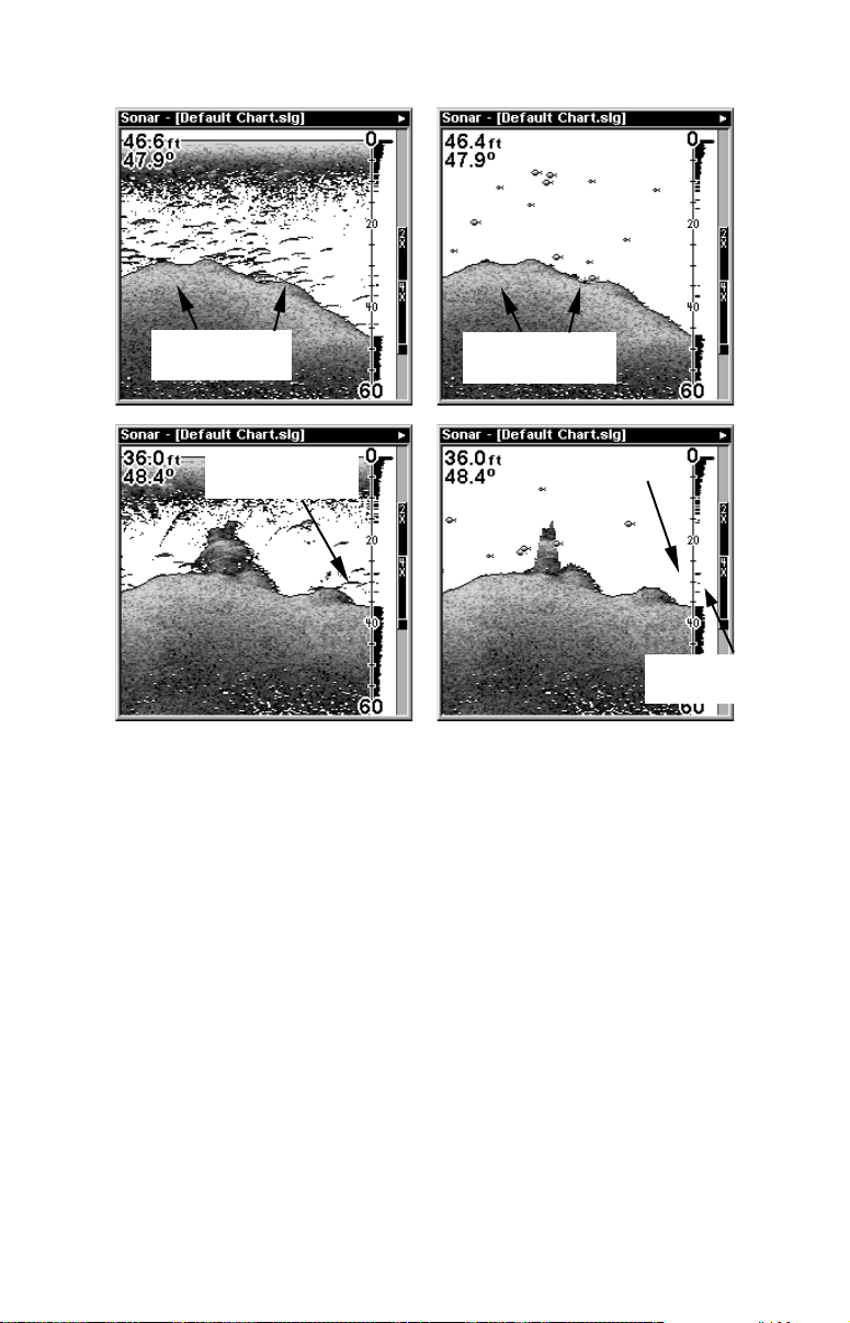
Fig. 1 A
Fig. 1 B
Many fish
arches visible
Fig. 2 A
Fish arches
above structure
Fewer fish
symbols visible
Fig. 2 B
No fish shown
FasTrack graph
confirms fish
At left, figures 1A and 2A show Sonar Page in normal chart mode. At
right, figures 1B and 2B show the same underwater scene with Fish I.D.
turned on. Note how arches are replaced with symbols.
To turn the Fish I.D. feature on:
1. From the Sonar Page, press
2. Press → ↓ or
→ to
F
ID S
ISH
YMBOLS
|↓ to
MENU
|
ENT|EXIT|EXIT
S
ONAR FEATURES
.
|
ENT
.
To turn off Fish I.D., repeat the instructions in step 1.
FishTrack
The FishTrack feature shows the depth of a fish symbol when it appears on the display. This lets you accurately gauge the depth of targets. This feature is available only when the Fish I.D. feature is on. The
default setting for FishTrack is off.
To turn on FishTrack:
(Note: These instructions will turn on FishTrack and Fish I.D. at the
same time.)
1. From the Sonar Page, press
MENU
|↓ to
S
ONAR FEATURES
|
ENT.
65
Page 74
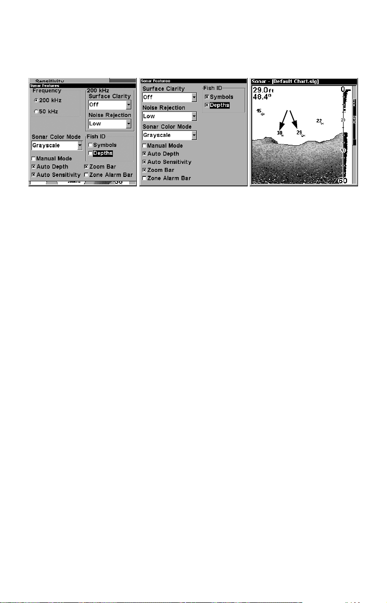
2. Press → ↓ to
p
F
ISH
ID D
|
ENT|EXIT|EXIT
EPTHS
.
To turn off FishTrack, repeat the instructions in step 1. Turning off
FishTrack in this manner will not turn off Fish I.D. symbols.
Symbols with
FishTrack de
ths
Sonar Features menu with Fish I.D. Depths selected (at left, dual-
frequency menu; center, single-frequency menu). When the check box to
the left is checked, the feature is on. At right, Sonar Page showing Fish
I.D. symbols and FishTrack depths turned on.
FishReveal
When displaying actual sonar returns, the FishReveal feature uses 10
levels of gray tones to show fish targets hidden by surface clutter,
thermoclines, weed beds and other cover.
The normal mode of operation (with FishReveal turned off) shows the
weakest echoes as black and the strongest echoes in light gray. Since
all weak echoes are black, fish arches show boldly against the white
background. The drawback is that all weak echoes – such as thermoclines – are also emphasized. This can make it hard to distinguish fish
signals inside thermoclines or other cover.
In FishReveal mode, the weakest echoes are white and the strongest
echoes are black. Echoes in between vary in gray in proportion to their
signal strength. The Grayline control determines the range for black to
white. Also note that when using FishReveal, we recommend that you
turn off Auto Sensitivity and turn up Sensitivity to near maximum.
66
Page 75
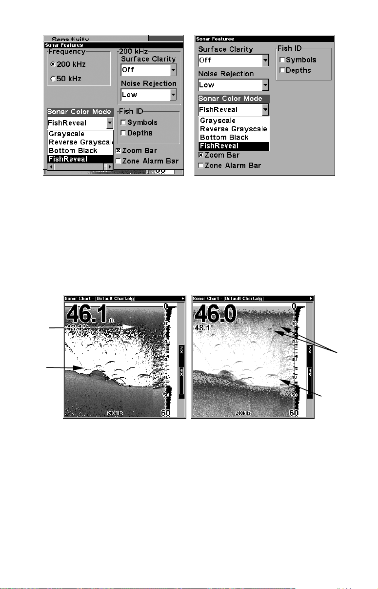
Sonar Color Mode command with FishReveal selected
(at left, dual-frequency menu; at right, single-frequency menu).
To turn FishReveal on:
1. From the Sonar Page, press
MENU
|↓ to
S
ONAR FEATURES
|
ENT
.
2. Press ↓ to
3. Press
EXIT
S
ONAR COLOR MODE
|↑ to
A
UTO SENSITIVITY
|
ENT
|
|↓ to
ENT
F
|↑ to
ISHREVEAL
S
ENSITIVITY
|
ENT
|
.
ENT
.
4. Press ↑ until the Sensitivity Control Bar reads 100% (or close to it),
then press
Fish
not
visible
Fish
arch
. (If you reach the maximum limit, a tone sounds.)
EXIT
Visible
fish
Fish
arches
Sonar chart in regular grayscale mode, left, and in FishReveal mode,
right. Notice how shallow fish formerly hidden in the surface clutter
become visible in FishReveal mode.
NOTE:
Water conditions vary greatly, and that affects sonar performance.
Under certain conditions, FishReveal will show you more fish than
normal grayscale mode, but the reverse will be true in other circumstances. We suggest you become familiar with both modes so you can
best match your sonar's performance to the current water conditions.
67
Page 76
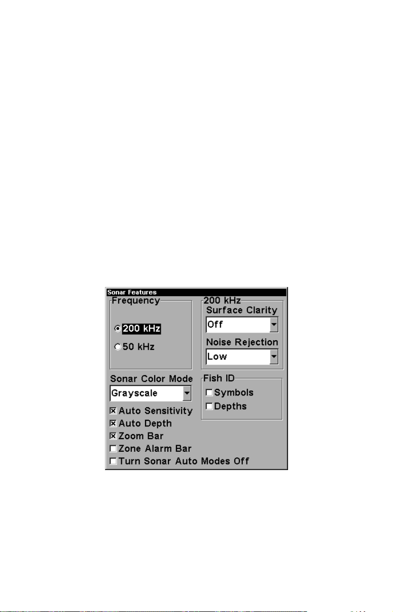
Frequency (Change Transducer Frequency)
(LMS-320DF only)
The LMS-320DF transducer operates with both 200 kHz and 50 kHz.
The 200 kHz frequency has a 12° cone angle and the 50 kHz frequency
has a 35° cone angle.
The default frequency is 200 kHz, which is best for use in shallow water
(about 300 feet or less). This frequency is the best choice for about 80
percent of the fresh and salt water sport fishing applications. When you
get into very deep salt water, 300 to 500 feet or deeper, the 50 kHz frequency is the best choice.
The 200 kHz transducer will give you better detail and definition, but
less depth penetration. The 50 kHz transducer will give you greater
depth penetration, but a little less detail and less definition. (Remember,
all sonar units typically read deeper in fresh water than in salt water.)
There is a common exception to these rules of thumb. Some fishermen
on freshwater lakes (or the ocean) using downriggers like to see them
on the sonar. In many of those cases, you'll see a 50 kHz transducer
frequency in use because the wider cone angle lets them watch the bait.
Sonar Features menu with a frequency of 200 kHz selected.
To change the frequency setting to 50 kHz:
1. From the Sonar Page, press
2. Press ↓ to
3. Press
EXIT|EXIT
|
50 KH
.
ENT
Z
to clear the menu.
MENU
|↓ to
S
ONAR FEATURES
68
|
ENT
.
Page 77
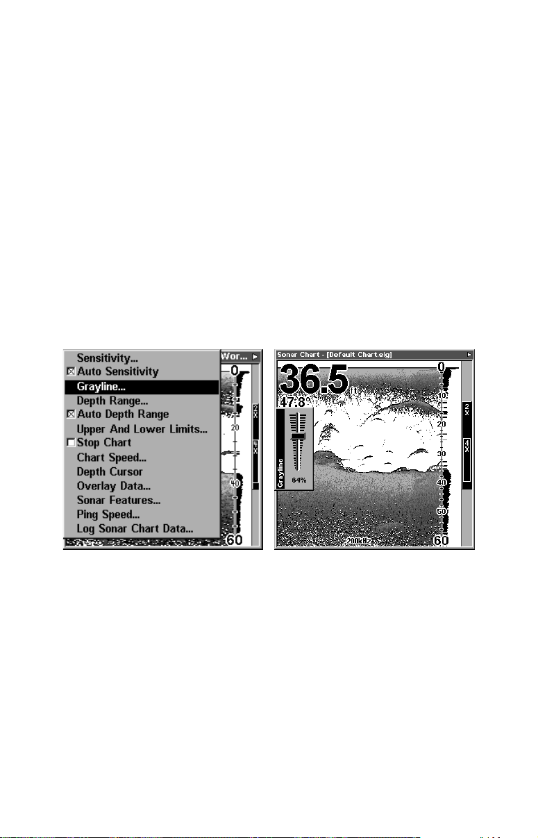
To change the frequency setting to 200 kHz:
|↓ to
1. From the Sonar Page, press
MENU
S
ONAR FEATURES
|
ENT|ENT
.
2. Press
EXIT|EXIT
Grayline
to clear the menu.
Grayline lets you distinguish between strong and weak echoes. It
"paints" gray on targets that are stronger than a preset value. This allows you to tell the difference between a hard and soft bottom. For example, a soft, muddy or weedy bottom returns a weaker signal which is
shown with a narrow or no gray line. A hard bottom returns a strong
signal which causes a wide gray line.
If you have two signals of equal size, one with gray and the other without, then the target with gray is the stronger signal. This helps distinguish weeds from trees on the bottom, or fish from structure.
Grayline is adjustable. Experiment with your unit to find the Grayline
setting that's best for you.
At left, Sonar Page menu with Grayline command selected.
At right, the Grayline control bar.
To adjust the Grayline level:
1. From the Sonar Page, press
MENU
|↓ to
G
RAYLINE
|
ENT
.
2. The Grayline Control Bar appears. Press ↓ to decrease Grayline;
press ↑ to increase Grayline.
3. When it's set at the desired level, press
EXIT
.
69
Page 78
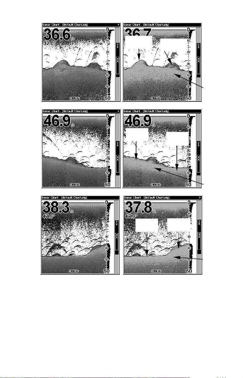
Fig. 1A
Fig. 1B
Fig. 2A
Fig. 3A
Hard
structure
Hard
bottom
Fish near
structure
Grayline
Fig. 2B
Muddy
bottom
Grayline
Fig. 3B
Muddy
bottom
Hard
bottom
Grayline
This series of figures shows how different Grayline settings can reveal
more information. The "A" figures to the left show locations with Grayline set at the factory level of 64 percent. At right, the "B" figures show
the same locations with Grayline increased to 84 percent. In Figure 1B,
no fish are near the left structure, but the right structure shows fish
holding next to the structure. Notice in figures 2B and 3B how Grayline displays a hard, rocky bottom (the drop-offs) with a wider gray
line. The muddier bottom below those drop-offs appears as a narrower
gray line.
70
Page 79
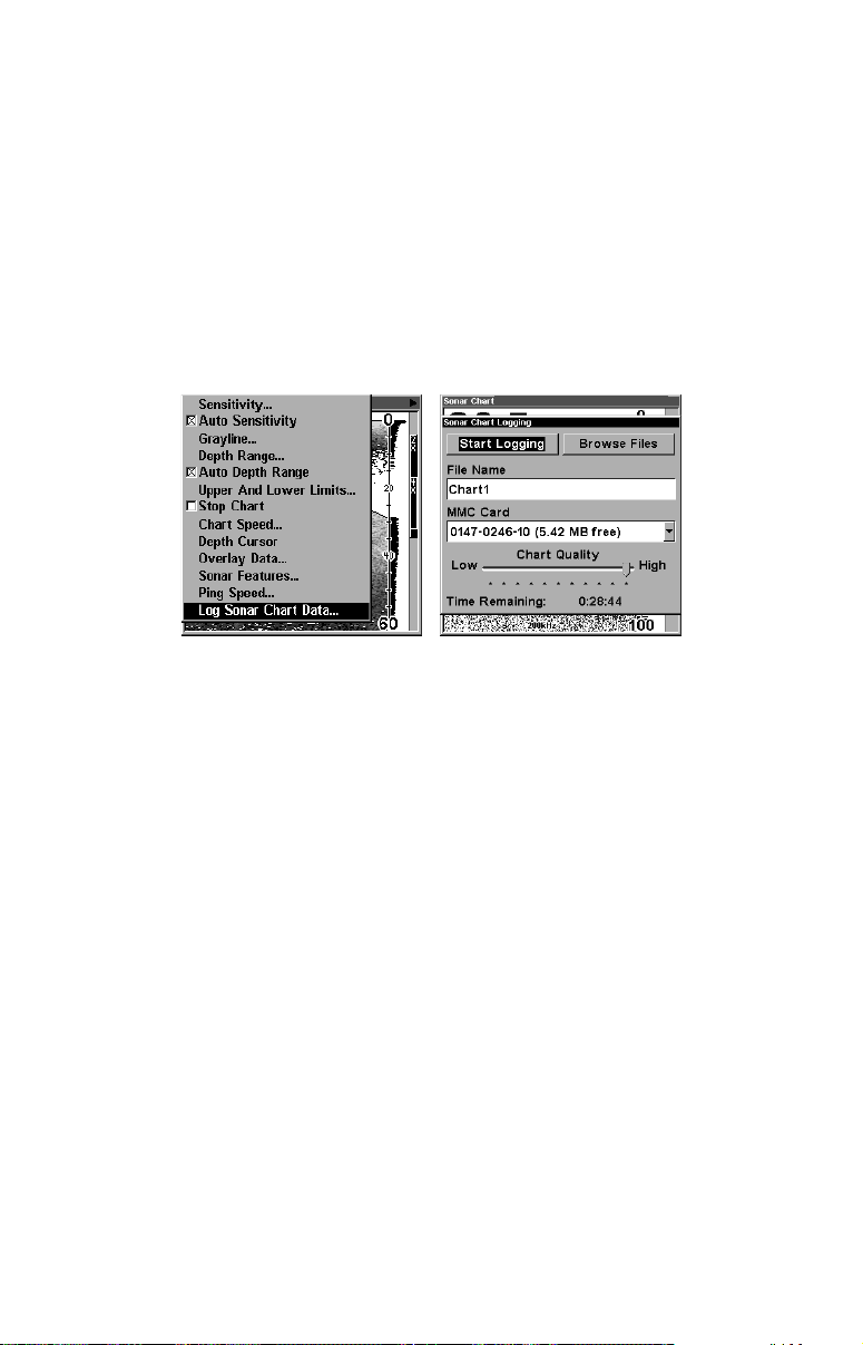
HyperScroll
See the entry on Ping Speed, which controls the HyperScroll feature.
Log Sonar Chart Data
If you have an MMC installed in the unit, the sonar data shown on the
screen can be saved to the MMC. This can be played back at any time
(to play a recorded sonar chart log, see the entry in this section for Sonar Simulator). If you have a personal computer and Internet access,
visit our web site, www.lowrance.com, and download the free Sonar
Viewer and the emulator for your unit. These programs will allow you
to replay sonar logs on your personal computer.
At left, the Sonar Page menu with the Log Sonar Chart Data command
selected. At right, Sonar Chart Logging menu, with the Start Logging
command selected. The menu says the MMC has 5.42 MB of free space,
which will record the scrolling chart for 28 minutes and 44 seconds.
To record or log chart data:
1. Press
2. To record data using the default settings, press
and the Sonar Page title bar shows the name of the file you are recording. Warning messages will appear as recording time begins to run out.
NOTE:
You can change any of the settings by using the cursor arrows to
highlight different commands. Select
change the name. Select
quality and record for a longer period of time. After you've changed
the settings, select
MENU
|↓ to
L
OG SONAR CHART DATA
C
HART QUALITY
S
TART LOGGING
.
|
.
ENT
. The menu clears
ENT
F
ILE NAME
if you want to
if you want to lower the file
Noise Rejection
See the entry on Advanced Signal Processing in this section.
Overlay Data
To change the digital data shown on top of the Sonar Page or the Map
Page:
71
Page 80
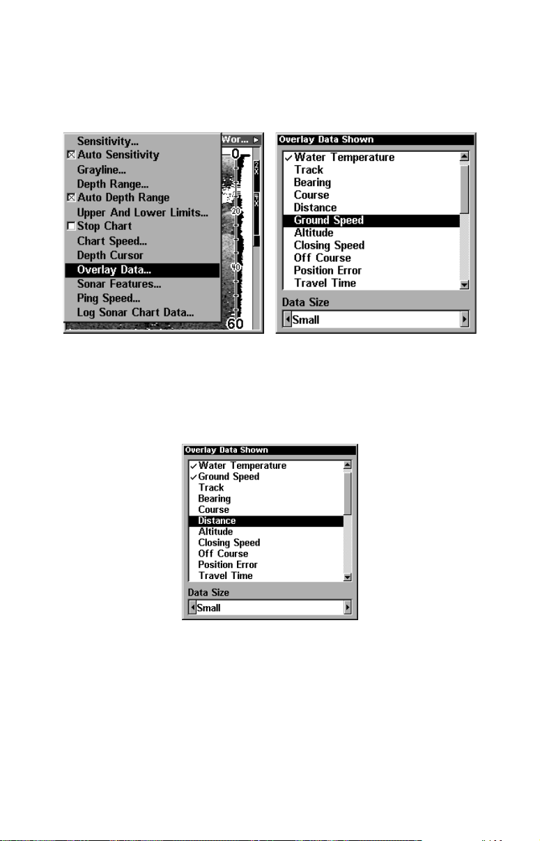
First, press
To select data for display:
PAGES
1. From the Map or Sonar page, press
2. Press ↓ or ↑ to select Data Type|
, use → or ← to select a Page Name, then press
ENT
MENU
.
|↓ to
O
VERLAY DATA
|
ENT
EXIT
.
Overlay Data command on the Sonar Menu, at left. Overlay Data
Shown selection menu, right. In this example, we scrolled down the
data list to highlight "Ground Speed."
When selected, the data type shifts to the top of the data list and a
check mark appears beside the data type. (If you wish, you may now
use ↓ or ↑ to select other Data Types for display.)
.
Data list showing "Ground Speed" selected to display on Sonar Page.
3. To return to the previous page, press
To turn off displayed data:
1. From the Map or Sonar page, press
2. Press ↓ or ↑ to select Data Type|
MENU
ENT
EXIT|EXIT
. The selected data type disap-
|↓ to
.
O
VERLAY DATA
|
ENT
.
pears from the top of the list and reverts to its previous, unchecked position. (If you wish, you may now use ↓ or ↑ to select other Data Types
to turn off.)
72
Page 81
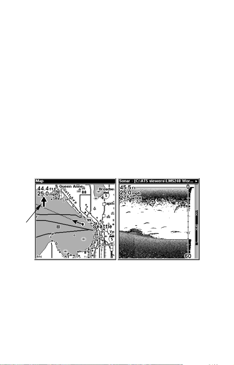
3. To return to the previous page, press
To change displayed data font size:
1. From the Map or Sonar page, press
MENU
EXIT|EXIT
|↓ to
.
O
VERLAY DATA
|
ENT
.
2. Press ↓ or ↑ to select Data Type|press → or ← to Data Size|
EXIT
.
The selected data type will be displayed in the new size. (To change the
font size for another Data Type, press
and repeat these steps, be-
ENT
ginning with step two above.)
3. To return to the previous page, press
EXIT
.
Tip:
If you wish, you can change the displayed data font size when you
select a data type:
1. From the Map or Sonar page, press
|
ENT
.
D
ATA
2. Press ↓ or ↑ to select Data Type|press → or ← to select Data
Size|
ENT
.
The data will be shown in the new font size. To return to the previous page, press
Steering
arrow
EXIT|EXIT
.
MENU
|↓ to
O
VERLAY
At left, Map Page showing boat cruising Puget Sound, Washington,
with Overlay Data turned on. This example shows Depth, Ground
Speed and the Steering Arrow. Note that the Steering Arrow always
points directly to the destination you are navigating toward. In this
case, the boater is headed on a northwesterly course of 275º. Since the
helmsman is on course, the Steering Arrow is pointing straight ahead.
If the helmsman veered off course, the arrow would show which direc-
tion to steer to get back on course toward the destination. At right,
Sonar Page with Overlay Data turned on. This example shows Depth,
Ground Speed and the Track the boat is following.
73
Page 82
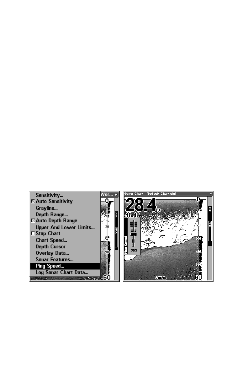
Ping Speed & HyperScroll
Ping Speed controls the rate at which the transmitter and transducer
broadcast sonar sound waves — pings — into the water. The unit has a
default ping speed of 50 percent. At normal boating speeds, this automatically provides enough return echoes to refresh the screen and scroll
the chart at maximum chart speed.
However, when you are running at high speeds, or just want the fastest
possible screen update, you may want to use the HyperScroll feature.
When you change the Ping Speed to any setting greater than 50 percent, the unit automatically enters HyperScroll mode.
These faster ping rates allow you to maintain a high-detail picture on
the screen, and the screen refresh rate and chart scroll speed can keep
pace with the boat as it moves quickly over the bottom terrain.
When using HyperScroll, you may also need to manually decrease the
sensitivity for optimum performance. Depending on water depth and
other conditions, HyperScroll may cause a second bottom echo to return
to the transducer during the next ping cycle, or sounding. This can result
in a large amount of clutter appearing on the screen. If this occurs, just
decrease the sensitivity to a level that eliminates the clutter. When you
turn HyperScroll off, you can return to your original sensitivity level.
At left, Sonar Menu with Ping Speed command selected.
Ping Speed Control Bar, right, at default setting.
To change Ping Speed:
1. From the Sonar Page, press
MENU
|↓ to
P
ING SPEED
|
ENT
.
2. The Ping Speed Control Bar appears. Press ↑ to increase ping speed;
press ↓ to decrease ping speed. When it's set at the desired level, press
EXIT
74
.
Page 83
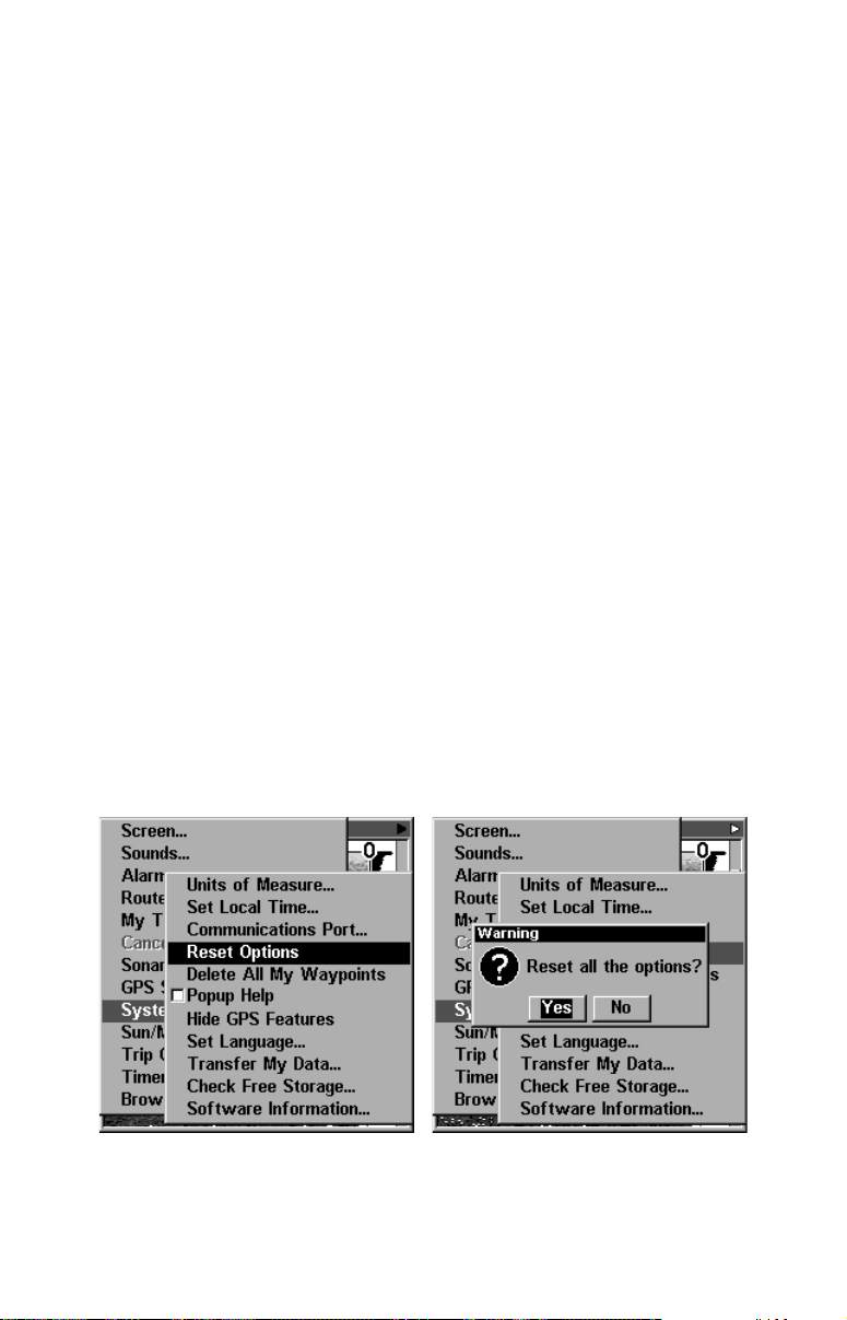
To adjust Sensitivity:
1. From the Sonar Page, press
MENU|ENT
.
2. The Sensitivity Control Bar appears. Press ↓ to decrease sensitivity;
press ↑ to increase sensitivity. When it's set at the desired level, press
. (When you reach the maximum or minimum limit, a tone sounds.)
EXIT
To turn off HyperScroll:
1. From the Sonar Page, press
MENU
|↓ to
P
ING SPEED
|
ENT
.
2. The Ping Speed Control Bar appears. Press↓ to decrease ping speed
to 50 percent. When it's set at the desired level, press
EXIT
.
When you boost ping speed and switch into HyperScroll, the width of
the FasTrack bar graph display doubles in width at the right side of the
screen. The allows you to better see the virtually instantaneous sonar
returns, just as you would on a flasher sonar unit. For more information on FasTrack, see it's entry in this section.
Reset Options
This command is used to reset all features, options and settings to their
original factory defaults. This is useful when you have changed several
settings and want to return the unit to basic automatic operation.
1. Press
MENU|MENU
2. Press ← to
Y
ES
|
ENT
|↓ to
.
S
YSTEM SETUP
|
ENT
|↓ to
R
ESET OPTIONS
|
ENT
.
3. All the menus are cleared and the unit reverts to the Map Page at
the 4000 mile zoom range, just as if you had turned it on for the first
time. All options have been returned to the factory settings.
At left, System Setup menu with Reset Options command selected. At
right, the Reset Options dialog box, with "Yes" selected.
75
Page 84

NOTE:
Reset Options does not erase any waypoints, routes, plot trails, or
sonar logs.
Reset Water Distance
The sonar chart's Digital Data display option includes a window that
shows distance traveled, called Water Distance ("W Distance"). This
information is calculated from an optional water speed sensor, not the
GPS. The Water Distance window can be reset to zero using the Reset
Water Distance command.
Press
TANCE
MENU|MENU
|
. The menus are cleared and the water distance is reset to 0.00.
ENT
|↓ to
S
ONAR SETUP
|
ENT
|↓ to
R
ESET WATER DIS-
Set Keel Offset
This unit measures water depth from the face of the transducer. Since
the transducer is installed below the water surface, the distance displayed by the digital depth, chart depth scale, chart cursor or fish symbols is not the exact water depth. If the transducer is 1 foot below the
surface, and the screen shows the water depth as 30 feet, then the actual depth is 31 feet.
On sailboats or other large vessels with deep drafts, the distance between the transducer installation and the keel or lower engine unit can
be several feet. In those cases, an inexact depth reading could result in
grounding or striking underwater structure. The Keel Offset feature
eliminates the need for the navigator to mentally calculate how much
water is under his keel.
Keel Offset lets you calibrate the digital depth: chart depth scale, chart
cursor depth and fish symbol depth displayed on the screen. To calibrate
the depth indicators, first measure the distance from the face of the
transducer to the lowest part of the boat. In this example, we will use 3.5
feet. This will entered as a negative 3.5 feet, which makes the depth indi-
cators perform as if the transducer's lower in the water than it really is.
1. Press
MENU|MENU
|↓ to
S
ET KEEL OFFSET
|
ENT
.
2. The Keel Offset dialog box appears. Press ↓ to change the plus (+)
sign to a minus (–) sign.
3. Press → to the first number, then press ↑ to change the number to 3
4. Press → to the second number, then press ↑ to change the number to
5, then press
. The depth indicators now accurately show the depth
EXIT
of water beneath the keel.
76
Page 85

NOTE:
If knowing the exact depth of water beneath the keel is less important, you can calibrate the depth indicators so that they show the actual water depth from surface to bottom. To do this, first measure the
distance from the face of the transducer up to the surface (the water
line on the boat). In this example, we will use 1.5 feet. This will be entered as a positive 1.5 feet, which makes the depth indicators perform
as if the transducer's higher in the water than it really is.
1. Press
MENU|MENU
|↓ to
S
ET KEEL OFFSET
|
ENT
.
2. The Keel Offset dialog box appears with a plus (+) sign at the
front of the box.
3. Press → to the first number, then press ↑ to change the number
to 1.
4. Press → to the second number, them press ↑ to change the number to 5, then press
. The depth indicators now accurately show
EXIT
the water depth from surface to bottom.
Sensitivity & Auto Sensitivity
The sensitivity controls the ability of the unit to pick up echoes. Sensitivity can be adjusted, because water conditions vary greatly. A low
sensitivity level (from zero to 50 percent) excludes much of the bottom
information, fish signals, and other target information.
High sensitivity levels let you see this detail, but it can also clutter the
screen with many undesired signals. Typically, the best sensitivity level
shows a good solid bottom signal with Grayline and some surface clutter.
Automatic Sensitivity
The default sensitivity mode is automatic. The unit bases the sensitivity level on water depth and conditions. When the unit is in the automatic mode, sensitivity is automatically adjusted to keep a solid bottom
signal displayed, plus a little more power. This gives it the capability to
show fish and other detail.
However, situations occur when it becomes necessary to increase or decrease the sensitivity. This typically happens when you wish to see
more detail, so an increase in sensitivity is indicated. Or, wave action
and boat wakes can create enough tiny air bubbles to clutter much of
the water column. In that case, a decrease in sensitivity is indicated to
reduce some of the clutter.
The control bar used to adjust sensitivity up or down is the same
whether the unit is in the automatic or manual mode. In automatic you
77
Page 86
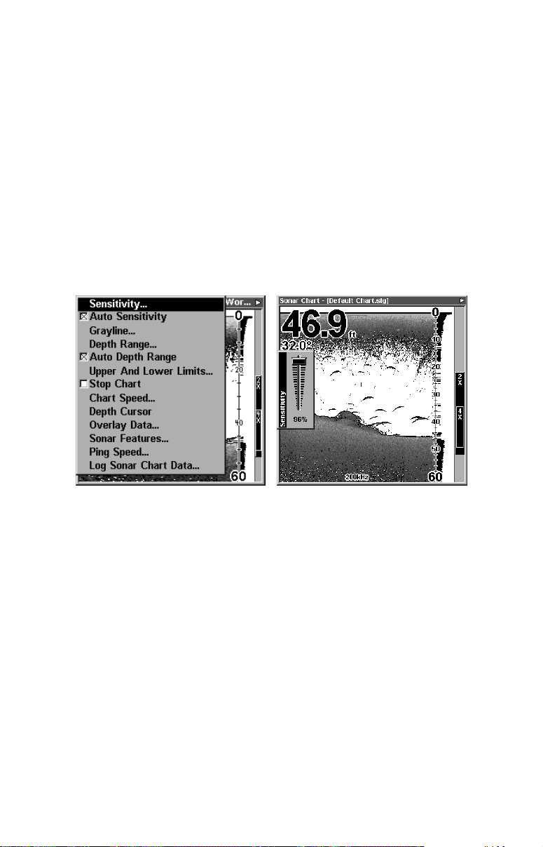
can adjust sensitivity up to 100 percent but the unit will limit your
minimum setting. In auto, the unit will continue to make small adjustments, allowing for the setting you selected.
In manual mode, you have complete control over sensitivity, with the
ability to set it anywhere from zero to 100 percent. Once you select a
level in manual, the unit will continue to use that exact sensitivity setting until you change it or revert to auto mode.
To adjust sensitivity in auto mode:
1. Press
MENU|ENT
.
2. The Sensitivity Control Bar appears. Press ↓ to decrease sensitivity;
press ↑ to increase sensitivity. When it's set at the desired level, press
. (When you reach the maximum or minimum limit, a tone sounds.)
EXIT
At left, Sonar Menu with Sensitivity command selected. At right, the
Sensitivity Control Bar.
To adjust sensitivity in manual mode:
1. First, turn off Auto Sensitivity: from the Sonar Page, press
to
A
UTO SENSITIVITY
2. Press ↑ to
|
ENT
S
ENSITIVITY
.
|
and the Sensitivity Control Bar appears.
ENT
MENU
|↓
Press ↓ or ↑ to pick a different sensitivity setting. When it's set at the
desired level, press
EXIT
.
To turn Auto Sensitivity back on:
From the Sonar Page, press
MENU
|↓ to
A
UTO SENSITIVITY
|
ENT|EXIT
NOTE:
To return to the original factory setting for Auto Sensitivity, see the
entry in this section on Reset Options. If sensitivity is in manual
mode, the Reset Options command will switch back to Auto and reset the factory setting at the same time.
78
.
Page 87
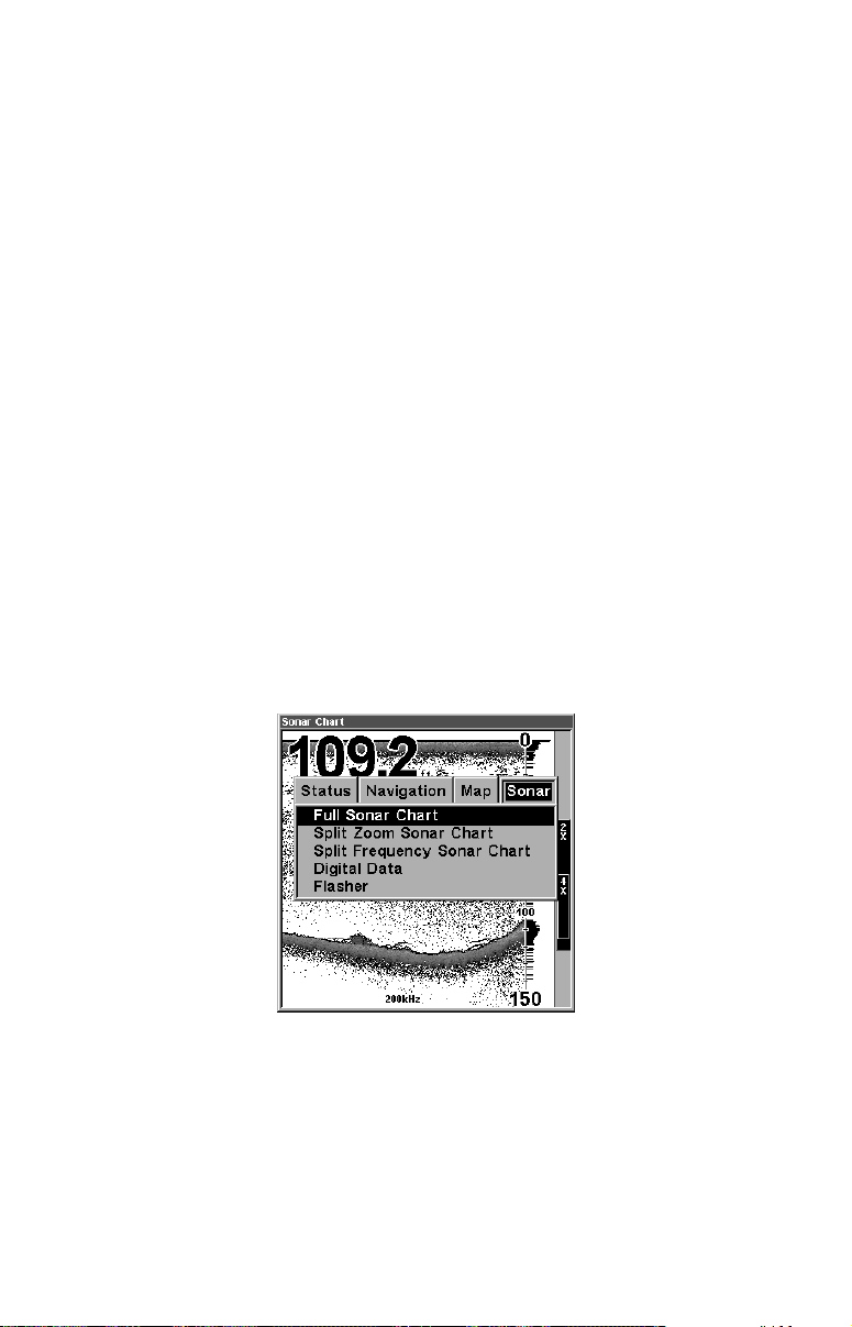
Tip:
For quicker sensitivity adjustments, try leaving the Sensitivity
Control Bar on the screen as the chart scrolls. You can see the
changes on the screen as you press the up or down arrows. This is
handy when there's a lot of clutter in the water, and you are
matching the sensitivity to rapidly changing water conditions.
Sonar Color Mode
The default color scheme for the sonar chart is grayscale, but we offer
other variations to suit your viewing preferences. You can select the
chart to be displayed in reverse grayscale, bottom black or FishReveal
mode. (For more information on FishReveal, see the entry on that topic
elsewhere in this section.)
To change the chart mode color scheme:
1. From the Sonar Page, press
2. Press ↓ to
S
ONAR COLOR MODE
3. Press ↓ or ↑ to Mode Name|
4. Press
EXIT|EXIT
to return to the Sonar Page.
MENU
|
ENT
ENT
|↓ to
.
.
S
ONAR FEATURES
|
ENT
.
Sonar Page & Sonar Chart Display Options
The Pages Menu offers five chart display options for dual-frequency
models and four options for single-frequency models. To access them,
press
PAGES
|← or→ to
|↓ to Option Name|
S
ONAR
EXIT
.
Pages Menu, showing sonar chart display options.
Full Sonar Chart
This is the default mode used when the unit is turned on for the first
time or when it's reset to the factory defaults.
The bottom signal scrolls across the screen from right to left. Depth
scales on the right side of the screen aid in determining the depth of
targets. The line at the top of the screen represents the surface. The
79
Page 88
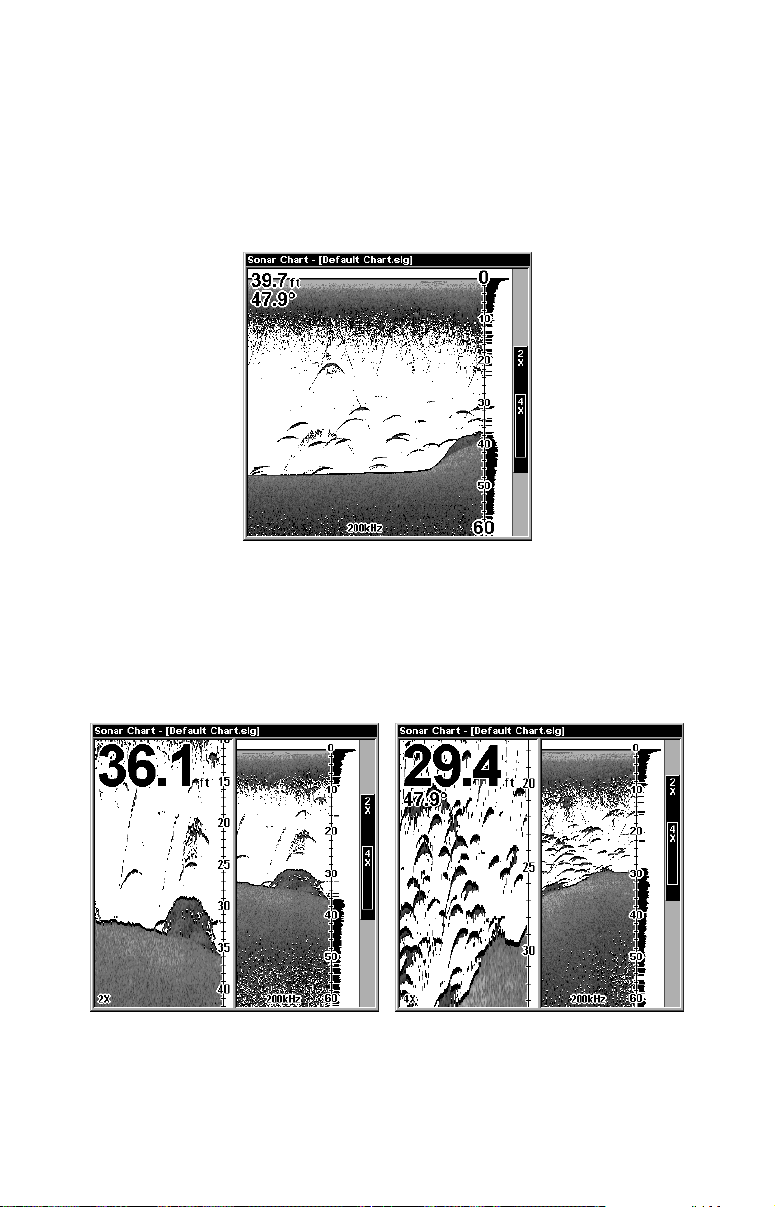
bottom depth and surface temperature (if equipped with a temperature
sensor or a transducer with a temp sensor built in) show at the top left
corner of the screen.
The FasTrack™ display shows just to the right of the scale. This
changes all echoes into short horizontal bars, replicating a flasher sonar. The zoom bar on the far right shows the area that's zoomed when
the zoom is in use. (See the Zoom section for more information.)
Full Sonar Chart. The Overlay Data (depth and water temperature)
are both set to the small text size.
Split Zoom Sonar Chart
A split chart shows the underwater world from the surface to the bottom on the right side of the screen. The left side shows an enlarged version of the right side. The zoom range shows at the bottom left corner of
the screen.
Split Zoom Sonar Chart. Image at left shows the left window zoomed to
2X. The right image shows the left window zoomed to 4X. The depth
overlay data is set to the default large text size; the water temperature
is set to the small text size.
80
Page 89
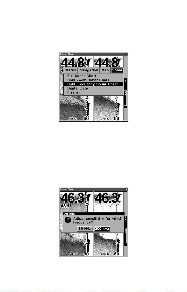
Split Frequency Sonar Chart
(LMS-320DF only)
This page shows sonar data from the 50 kHz transducer element on the
left side of the screen and data from the 200 kHz transducer on the
right side. All other functions and features are the same as the Full
Chart page.
Split Frequency Sonar Chart page, with
50 kHz view at left and 200 kHz view at right.
You can adjust the sensitivity in each window.
To adjust sensitivity in auto mode:
1. Press
MENU|ENT
.
2. The unit asks which you wish to adjust. Press ← or→ to select the
one you want |
ENT
.
3. The Sensitivity Control Bar appears. Press ↓ to decrease sensitivity;
press ↑ to increase sensitivity. When it's set at the desired level, press
. (When you reach the maximum or minimum limit, a tone sounds.)
EXIT
The Split Frequency Sonar Chart page allows you to adjust
sensitivity separately for each window.
81
Page 90
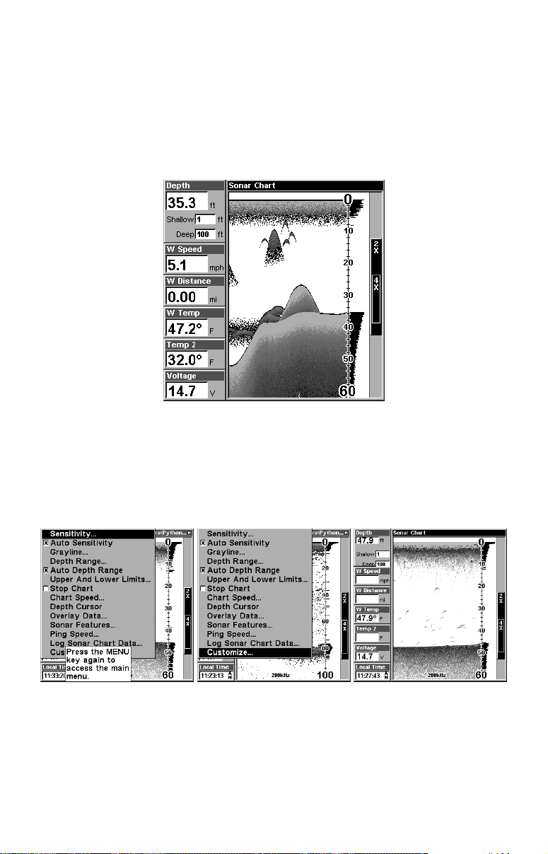
Digital Data/Chart
This mode shows the chart on the right side of the screen. The left side has
six large digital boxes or windows containing: Water Depth; Water Speed
(from an optional speed sensor); Water Distance (distance traveled or log, it
also requires a speed sensor); Surface Water Temperature; Temperature #2
and Temperature #3. (Note: Temperature #2 and #3 require additional
optional temperature sensors.)
Digital Data/Chart
Customizing the Digital Data/Chart Screen
The Digital Data/Chart screen can be customized to show digital data
different from the defaults first shown. To customize this screen:
1. From the Sonar Page (in Digital Data mode), press
|
C
USTOMIZE
. (Keep scrolling down and Customize will appear.)
ENT
MENU
|↓ to
The Customize command will not appear until you begin
scrolling down the Sonar Page menu. At far left, the
pop-up help box conceals part of the menu.
2. The W Speed window title bar flashes, indicating the window con-
tents can be changed. Press
|↑ or ↓ to select data type|
ENT
ENT|EXIT
.
82
Page 91
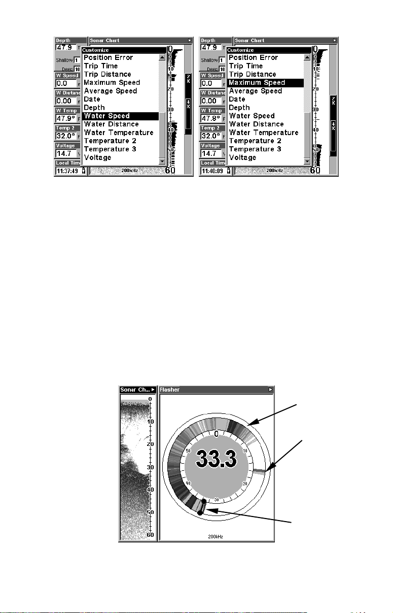
Options List for customizing Digital Data windows. At left, the list first
appears with Water Speed selected. At right, Maximum Speed has been
picked to replace Water Speed in the top digital data window.
Tip:
You can customize other digital data windows before returning to
the Sonar Page. After changing the first window by selecting the
Data Type and pressing Enter, use the ↓ key to select another window to change. When the selected window title bar flashes, press
|↑ or ↓ to select data type|
ENT
finished customizing, then press
Flasher
The Flasher page represents a flasher style sonar. A circular dial shows
all returning echoes at a high screen refresh rate. It uses the Grayline
feature to show weaker targets as shades of gray. The bottom depth is
also shown as a black bar across the outer circle. There is also a narrow
chart display on the left of the screen.
. Repeat these steps until you're
ENT
to return to the Sonar Page.
EXIT
Surface clutter
Fish signal,
approximately
16 feet
Flasher page.
83
Bottom signal
Page 92
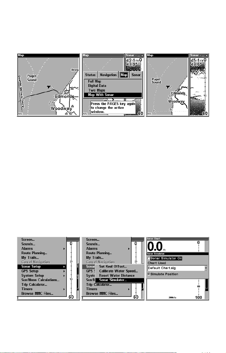
Map With Sonar Split Screen
There is a page mode that splits the screen in half, with the map on the
left and the sonar on the right. This screen option can be found on the
Pages Menu under the Map Page category.
Map With Sonar split screen option. At far right, the full Map Page is
shown. The Pages Menu with the Map option list is shown in the
center. At right, the Map With Sonar split screen is shown.
When this screen is activated, you need to specify which side the Menu,
Zoom In and Zoom Out keys correspond to. To do this, press
PAGES|PAGES
is the active window. To switch back, just press
. The window with the black title bar at the top of the screen
PAGES|PAGES
again.
Sonar Simulator
This unit has a built-in simulator that lets you run it as if you were on
the water. All sonar features and functions are useable. When in
simulator mode, you will see the chart file name in the Sonar Page title
bar and a play symbol will flash on and off at the right end of the title
bar. To use the simulator:
1. From the Sonar Page, press
|
S
ONAR SIMULATOR
ENT
.
MENU|MENU
|↓ to
S
ONAR SETUP
|
ENT
|↓ to
At left, Main Menu with Sonar Setup command selected. Center, sub-
menu with Sonar Simulator command selected. At right, Sonar Simu-
lator menu, with simulator turned off (check box is unchecked).
84
Page 93
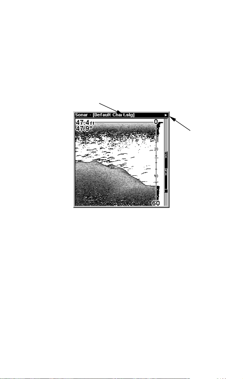
NOTE:
With Simulate Position checked, the simulator will also automatically run the GPS simulator (if GPS data was recorded with the sonar log).
2. To use the default sonar chart log stored in the unit, press
ENT|EXIT
The recorded chart begins scrolling across the screen, just as if you
were on the water.
3. Turn off Sonar Simulator by pressing
|
S
ETUP
Title bar with chart file name
Sonar Page, playing a recorded sonar chart in Sonar Simulator mode.
ENT
|↓ to
S
ONAR SIMULATOR
|
ENT|ENT|EXIT
MENU|MENU
.
|↓ to
"Play"
symbol
flashing
S
ONAR
Tip:
The Sonar Simulator can use sonar charts that you or a friend have
recorded (logged) on an MMC card. (To see how, read the entry in
this section on Log Sonar Chart Data.) To play back your own sonar
chart, make sure the MMC containing the chart is installed, then:
1. Press
2. Press ↓ to
MENU|MENU
C
3. Press ↓ or ↑ to select chart name|
|
O
N
ENT|EXIT
.
While you're in the Sonar Simulator menu, don't forget to check
Simulate Position if you want to run the sonar and GPS simulators
simultaneously. As you review sonar logs, you can create waypoints
to mark sites you want to return to.
While the simulator is running, you can switch from one chart log
to another by opening the Sonar Simulator menu and using the instructions in step 2 to select a different chart.
|↓ to
HART USED
S
ONAR SETUP
|
ENT
|
ENT
|↓ to
S
ONAR SIMULATOR
|
ENT
.
|↑ to
ENT
S
ONAR SIMULATOR
85
.
.
Page 94
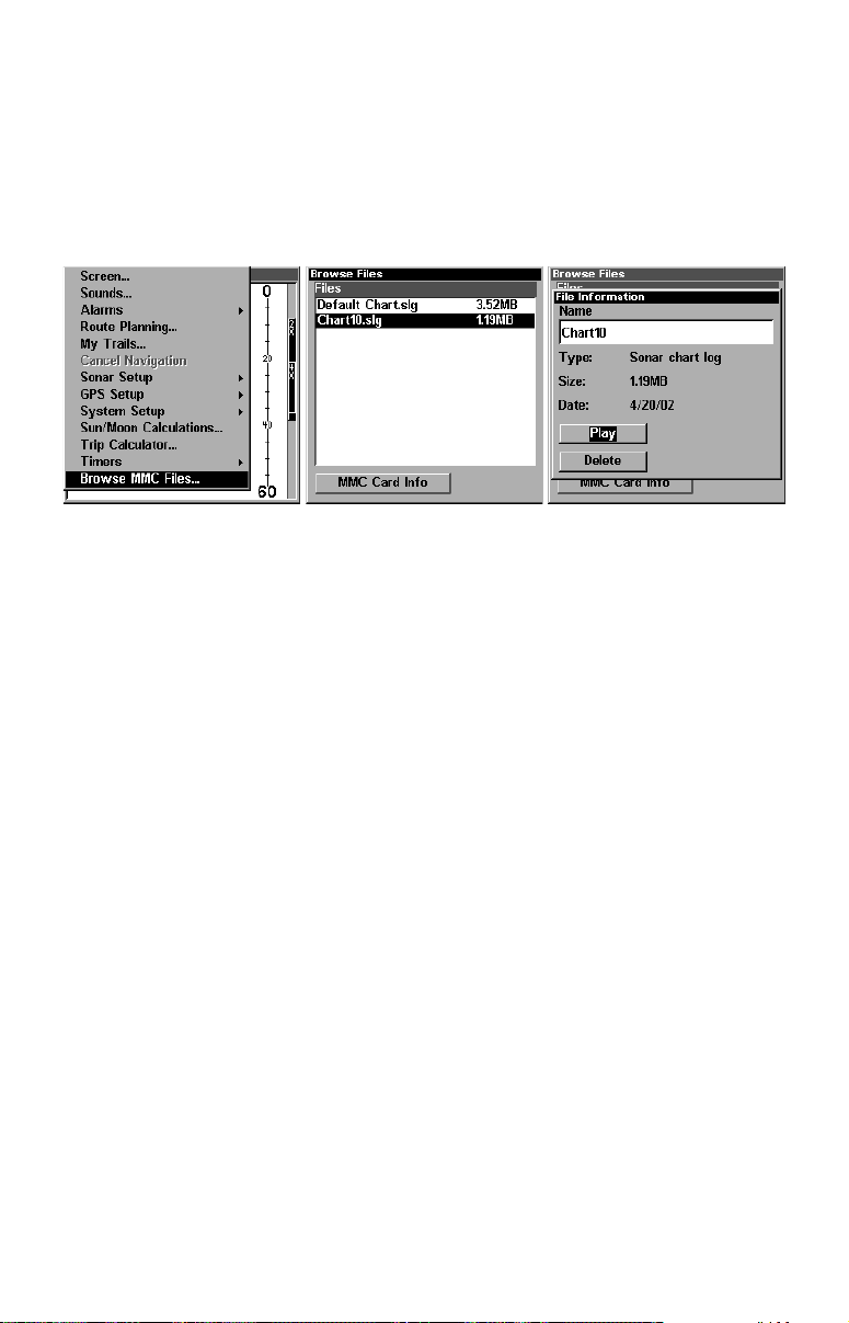
Tip:
There's more than one way to play a recorded sonar chart. You can
also turn on the simulator from the MMC files list. Here's how:
1. Press
MENU|MENU
2. Press ↓ or ↑ to chart name|
|↓ to
B
ROWSE
ENT
MMC F
|↓ to
P
ILES
LAY
|
ENT|ENT
|
ENT|EXIT
.
.
Menu sequence for playing a sonar chart log from the MMC File List.
NOTE:
For some great practice, try running the Sonar Simulator and the
GPS Simulator at the same time. This will really give you a feel for
how the unit will work in the field.
NOTE:
If you turn on your unit before attaching a transducer, it may enter
a demo mode. The words "demo mode" flash on the bottom of the
screen and a sonar chart plays much like the simulator. Unlike the
simulator, the demo mode is for demonstration only, and will automatically stop as soon as you turn on the unit with a transducer attached. The simulator will continue to function normally.
Stop Chart
If you are running multiple units on a boat or using this unit in a car,
there are times when you may want to turn off the sonar. This command turns off the sonar and stops the chart from scrolling. Sonar restarts automatically each time you turn on your unit.
Press
To turn on sonar and start the chart scrolling again, repeat the above step.
MENU
|↓ to
S
TOP CHART
|
ENT|EXIT
.
86
Page 95
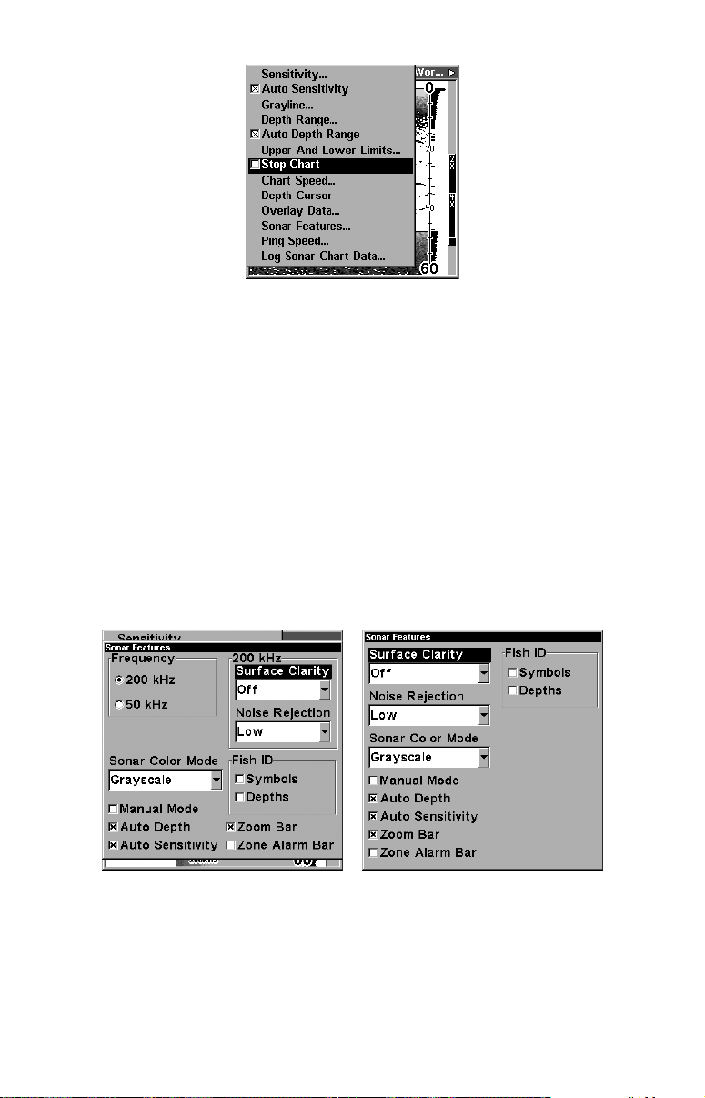
Sonar Menu with Stop Chart command selected. The box is unchecked,
indicating that the chart is scrolling across the screen.
Surface Clarity
The markings extending downward from the zero line on the chart are
called "surface clutter." These markings are caused by wave action,
boat wakes, temperature inversion and more.
The surface clarity control reduces or eliminates surface clutter signals
from the display. It does this by changing the sensitivity of the receiver,
decreasing it near the surface and gradually increasing it as the depth
increases.
There are three levels of surface clarity available: low, medium, or high.
It can also be turned off. The default level is off.
To adjust the Surface Clarity level:
1. From the Sonar Page, press
MENU
|↓ to
S
ONAR FEATURES
|
ENT
.
Sonar Features menu with Surface Clarity selected (at left, dual-
frequency menu; at right, single-frequency menu).
2. Press → to
press
ENT
S
URFACE CLARITY
).
3. Press ↓ or ↑ to select clarity level|
|
(For single-frequency units, just
ENT.
EXIT|EXIT|EXIT
.
87
Page 96
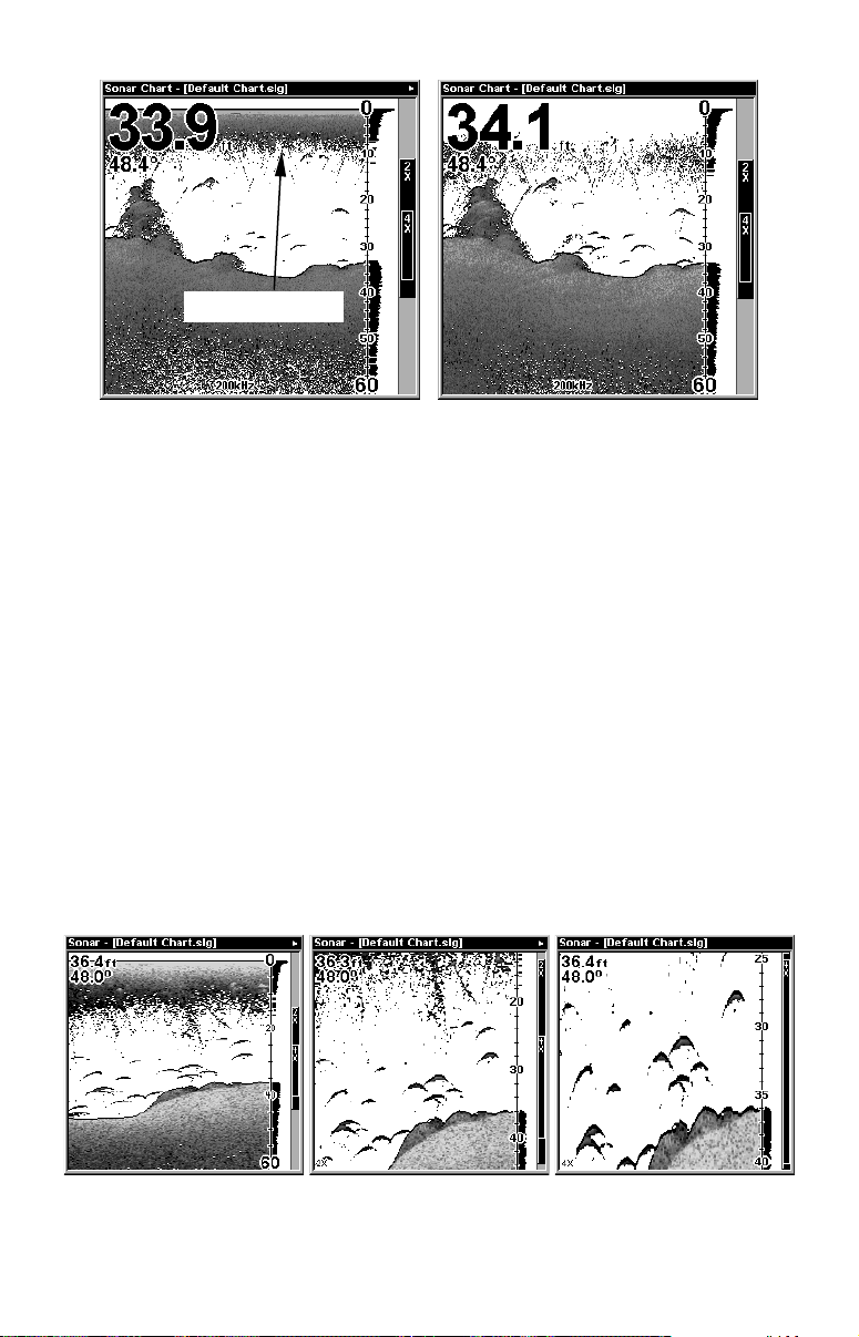
Surface clutter
In the illustration at left, Surface Clarity is turned off.
The right view shows Surface Clarity set at High.
Upper and Lower Limits
See the entry in this section for Depth Range - Upper and Lower Limits
Zoom & Zoom Bar
"Zooming" the display is a common, fast and easy method used to enlarge small detail, fish signals and the bottom with its associated structure. This unit lets you zoom the display quickly and easily by pressing
the Zoom In key,
Pressing
once doubles the size (2X) of all echoes on the screen.
ZIN
Pressing it again quadruples the size of the echoes (4X). The zoom bar
on the far right side of the screen shows which echoes will be displayed
on the screen when the
For example, pressing the
will show all echoes that are between the top and bottom of the 2X
zoom bar. Pressing the key again will give a 4X zoom and only the echoes between the top and bottom of the 4X bar will show on the screen.
Press the Zoom Out key,
ZIN
.
key is pressed.
ZIN
ZOUT
key once will enable a 2X zoom which
ZIN
, to return the display to the normal mode.
At left, Sonar Page, normal view. Center, same view zoomed to 2X.
Right, same view zoomed to 4X
88
Page 97

Zoom & Zoom Pan
Your unit has the handy ability to quickly zoom in on any portion of the
water column with just the touch of an arrow key. The Zoom Pan feature
lets you rapidly move the zoomed area up and down to different depths.
By "pointing" your zoom at different portions of the chart as it scrolls,
you can get a good, close-up look at structure or cover below you.
To use Zoom Pan, switch to a manual depth Range setting (see page 61)
and turn on 2X or 4X Zoom. Then, simply press ↑ or ↓
down the water column.
to pan up and
89
Page 98

Notes
90
Page 99

Section 5:
Sonar Troubleshooting
If your unit is not working, or if you need technical help, please use the
following troubleshooting section before contacting the factory customer
service department. It may save you the trouble of returning your unit
for repair. For contact information, refer to the last page, just inside the
back cover of this manual.
Unit won't turn on:
1. Check the power cable's connection at the unit. Also check the wiring.
2. Make certain the power cable is wired properly. The red wire
connects to the positive battery terminal, black to negative or ground.
3. Check the fuse.
4. Measure the battery voltage at the unit's power connector. It should
be at least 11 volts. If it isn't, the wiring to the unit is defective, the
battery terminals or wiring on the terminals are corroded, or the
battery needs charging.
Unit operates only in demo mode:
The transducer has not yet been connected or has been disconnected.
To leave demo mode, make sure the transducer is securely connected
before turning the unit on.
Unit freezes, locks up, or operates erratically:
1. Electrical noise from the boat's motor, trolling motor, or an accessory
may be interfering with the sonar unit. Rerouting the power and
transducer cables away from other electrical wiring on the boat may
help. Route the sonar unit's power cable directly to the battery instead
of through a fuse block or ignition switch
2. Inspect the transducer cable for breaks, cuts, or pinched wires.
3. Check both the transducer and power connectors. Make certain both
are securely plugged in to the unit.
Weak bottom echo, digital readings erratic, or no fish signals:
1. Make certain the transducer is pointing straight down. Clean the
face of the transducer. Oil, dirt and fuel can cause a film to form on the
transducer, reducing its effectiveness. If the transducer is mounted
inside the hull, be sure it is shooting through only one layer of
fiberglass and that it is securely bonded to the hull. Do NOT use RTV
silicone rubber adhesive or Marine-Tex epoxy.
2. Electrical noise from the boat's motor can interfere with the sonar.
91
Page 100

This causes the sonar to automatically increase its Discrimination or
noise rejection feature. This can cause the unit to eliminate weaker
signals such as fish or even structure from the display.
3. The water may be deeper than the sonar's ability to find the bottom.
If the sonar can't find the bottom signal while it's in the automatic
mode, the digital sonar display will flash continuously. It may change
the range to limits far greater than the water you are in. If this
happens, place the unit in the manual mode, then change the range to a
realistic one, (for example, 0-100 feet) and increase the sensitivity. As
you move into shallower water, a bottom signal should appear.
4. Check the battery voltage. If the voltage drops, the unit's transmitter
power also drops, reducing its ability to find the bottom or targets.
Bottom echo disappears at high speeds or erratic digital
reading or weak bottom echo while boat is moving
1. The transducer may be in turbulent water. It must be mounted in a
smooth flow of water in order for the sonar to work at all boat speeds. Air
bubbles in the water disrupt the sonar signals, interfering with its ability
to find the bottom or other targets. The technical term for this is cavitation.
2. Electrical noise from the boat's motor can interfere with the sonar.
This causes the sonar to automatically increase its Discrimination or
noise rejection feature. This can cause the unit to eliminate weaker
signals such as fish or even structure from the display. Try using
resistor spark plugs or routing the sonar unit's power and transducer
cables away from other electrical wiring on the boat.
No fish arches when the Fish I.D. feature is off:
1. Make certain the transducer is pointing straight down. This is the
most common problem if a partial arch is displayed.
2. The sensitivity may not be high enough. In order for the unit to
display a fish arch, it has to be able to receive the fish's echo from the
time it enters the cone until it leaves. If the sensitivity is not high
enough, the unit shows the fish only when it is in the center of the cone.
3. Use the Zoom feature. It is much easier to display fish arches when
zoomed in on a small range of water than a large one. For example, you
will have much better luck seeing fish arches with a 30 to 60 foot range
than a 0 to 60 foot range. This enlarges the targets, allowing the
display to show much more detail.
4. The boat must be moving at a slow trolling speed to see fish arches.
If the boat is motionless, fish stay in the cone, showing on the screen as
straight horizontal lines.
92
 Loading...