

Page 1
Pub. 988-0154-441
EP-35 TH
Electronic Temperature Sensor
Installation Instructions
This instruction sheet tells how to install your EP-35 TH thru-hull
temp sensor and connect it to a NMEA 2000
LowranceNET network components. You must refer to your digital
gauge, sonar or GPS unit's manual for sensor operation instructions.
Caution:
Installing LowranceNET NMEA 2000 devices is significantly
different from installing earlier Lowrance components without
NMEA 2000 features. You should read all of the installation instructions before proceeding. You should decide where to install
all components before drilling any holes in your vessel.
Some sonar or GPS units may require a software upgrade to display
NMEA 2000 data correctly and a manual addendum describing how to
operate the sensor. You can download these free and get additional
information on the NMEA 2000
our web site, www.lowrance.com.
All Lowrance NMEA 2000 capable devices are either NMEA 2000 certified or certification is pending. See our web site for the latest product
status information.
compatible LowranceNET system at
network using
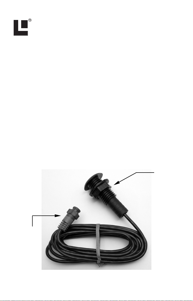
Temp
sensor
module
Blue female
NMEA 2000
connector
The EP-35 TH temperature sensor.
1
Page 2
The EP-35 TH consists of a temp sensor module and a blue female
locking cable connector. The cable length from the connector to the
temp module is 10 feet (3 m). The sensor module contains a thermometer and electronic components that convert temp data to the NMEA
2000 data format.
Caution:
The maximum hull thickness for the EP-35 TH is 1-1/4" (31
mm).
The EP-35 TH Temp sensor is designed to operate in a temperature
range of 4° to 176° F (-20° to 80° C). This sensor is designed to measure
surface water temperature.
The EP-35 TH Temp, like the other Lowrance Electronic Probe (EP)
sensors, is designed only for use with a NMEA 2000 Network. It must
be connected to a NMEA 2000 network or it will not function.
Tools and Supplies
Your EP sensor packs with a T connector needed to attach it to a
LowranceNET NMEA 2000 network. If you are connecting to an existing LowranceNET network, those are all the electronic components you
need. If this is the first sensor you are connecting, you will also need a
one-time purchase of a LowranceNET Node Kit.
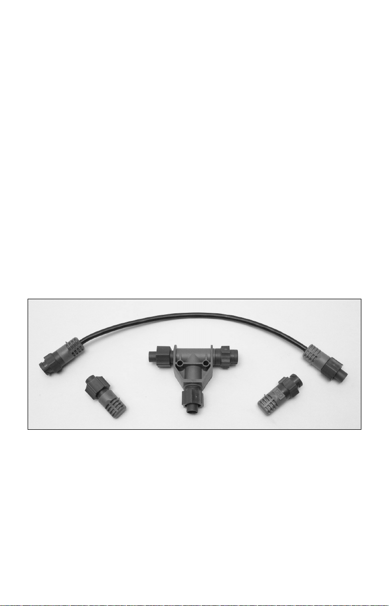
LowranceNET Node Kit for a NMEA 2000 network. Includes a 2-foot
extension cable, T connector, 120-ohm male terminator and 120-ohm
female terminator.
For complete instructions on setting up a new NMEA 2000 network or
expanding an existing one refer to the "Setup and Installation of NEMA
2000 Networks, General Information" document (part number 9880154-172) included with your EP-35 TH sensor. If that document is
missing it can be downloaded free from the Lowrance web site.
2
Page 3
Recommended Tools and supplies
Recommended tools for this job include: drill, 1/8" (3 mm) drill bit for pilot
hole, 1-1/16 (27 mm) hole saw with a blade type appropriate for the composition of your transom.
Required supplies for this job include: high quality, marine grade above- or
below-waterline sealant/adhesive compound. We recommend 3M Polyurethane Marine Adhesive Sealant 5200 or an equivalent brand. The sensor is
packed with a lock nut used for mounting.
Installation
1. The EP-35 TH thru-hull temperature sensor can be mounted in any
location on the hull, with the most common application being on the
transom. Wherever you install it, make sure the temp module will be in
contact with the water at all times and that it does not interfere with
the boat's trailer.
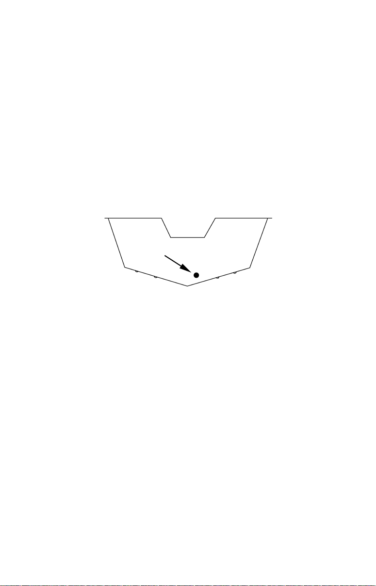
Suggested
location
To install the EP-35 TH, use a hole saw to cut a 1-1/16" (27 mm) hole in
the transom. The hole should be below the waterline.
2. After you've determined the proper location on the transom for the
EP-35 TH, drill a 1/8" (3 mm) pilot hole from inside the transom.
3. The EP-35 TH requires a 1-1/16" (27 mm) hole. Using a hole saw,
drill from the outside of the transom to prevent the gel coat from
cracking on fiberglass boats. Use eye and face protection when drilling
the hole. Afterwards, clean the area around the hole with detergent or
alcohol and let it dry. This will remove any cutting debris establish a
good surface for the adhesive.
5. Using a high quality, marine-grade above- or below-waterline sealant/adhesive compound, apply a 1/8" (3 mm) bead of sealant around the
lip of the EP-35 TH housing.
6. Make sure the nut has been removed from the sensor module, then
from the outside of the transom, pass the EP-35 TH cable through the
hole and push the housing with sealant into it. Use a twisting motion to
squeeze out excess sealant. Remove excess sealant from the outside of
the transom before it dries.
3
Page 4
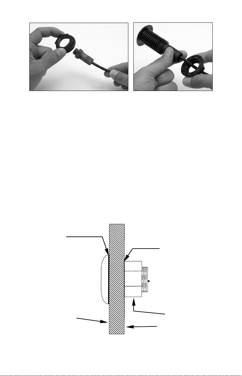
Slide the nut over the blue locking collar (left). Place the nut on the
sensor module, add sealant on the inside of the hull and tighten the
nut (right).
7. On the inside of the hull, slide the nut over the back end of the sensor module and add a 1/8" bead of sealant around the edge of the hole
on the inside of the transom. Hand-tighten the nut, being careful not to
over-tighten. Do not use a wrench to tighten the nut! Remove excess
sealant from the inside of the hull before it dries.
8. Route the EP-35 TH cable to the T on the network backbone where
you intend to attach it, and plug it in.
NOTE:
Allow the sealant/adhesive compound to dry for 12 hours before
putting your boat in the water.
9. Check for leaks! After the boat is launched, check for leaks immediately. Check the boat for leaks again several times during the next 24
hours. If you notice any leakage at all, the EP-35 TH should be reinstalled with a new coat of adhesive.
sealant
sealant
outer hull
Cross section of transom showing EP-35 TH installed.
nut
Inner hull
4
Page 5
Connecting to a NMEA 2000 Network
A network bus is an installed and operational network cable (backbone)
running the length of your boat, already connected to a power supply
and properly terminated. Such a bus provides network connection
nodes at various locations around your boat.
This is similar to the telephone wiring in a house. If you pick up a
phone in your living room, you can hear someone talking into the phone
in the bedroom.
Network Nodes
A network bus is built of network nodes spread along a backbone. Network nodes are made by fitting T-shaped connectors into the backbone
(using the sockets on the sides), and attaching a display unit or sensor at
the bottom of the T. Using our telephone example, the T connectors are
similar to telephone jacks. The backbone is like the phone wiring running through a house. Phones in a house must be connected to each other
to communicate, and in the same way only sensors and display units
plugged into the NMEA network can share information.
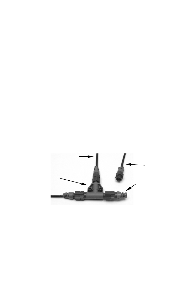
Connections found in the middle of the bus will have one or more of these
T-shaped connectors with the backbone cables plugged into both sides.
Connections at the end of a network will have the backbone plugged into
one side, and a terminator plugged into the other, as shown in the following figure.
Cable from
sensor or
display unit
LEI or Lowrance
device needs an
open T.
T connector
Backbone cable
(to rest of bus)
NMEA 2000 network node located at the end of a NMEA 2000 bus.
Terminator at
the very end
of the bus
Adding a Network Node
You can add a node anywhere along the network backbone where a connection already exists. This connection could be at the end of the network
(between a T connector and a terminator), between two T connectors,
between a T connector and a backbone extension cable, or between two
extension cables. Wherever you want to add the new node, simply separate the sockets of the old connection and attach your new T connector
between them.
5
Page 6
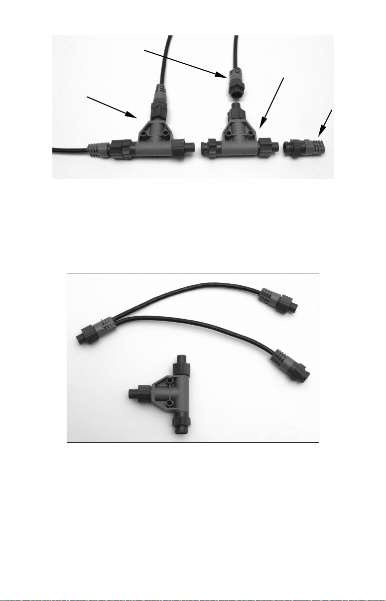
Lowrance or LEI device con-
nects to new T connector.
Existing network
node
Add a new device to a NMEA 2000 bus by attaching a T connector be-
tween two T connectors, between a T connector and the end terminator,
or between two backbone extension cables.
Add T-shaped connector to add device
to bus.
Attach
terminator at
end of bus.
If you want to add a node at the end of the line (as shown in the previous
figure), remove the terminator from the very last connector, securely attach the new T connector, and then attach the terminator on the new
connector. Either method will allow you to add a device.
The "soft" T connector, shown above with a "hard" T connector, is another
option for connecting devices in a NMEA 2000 network. The soft T works
the same as a hard T. The soft T is used to install a network node in areas
were a hard T will not fit.
Additional Network Information
Further instructions on creating or expanding a network are illustrated
in the NMEA 2000 network setup booklet, part number 988-0154-172,
which came packed with this instruction sheet.
6
Page 7

LOWRANCE ELECTRONICS
FULL ONE-YEAR WARRANTY
"We," "our," or "us" refers to LOWRANCE ELECTRONICS, INC., the manufacturer of
this product. "You" or "your" refers to the first person who purchases this product as a
consumer item for personal, family or household use.
We warrant this product against defects or malfunctions in materials and workmanship,
and against failure to conform to this product's written specifications, all for one (1) year
from the date of original purchase by you. WE MAKE NO OTHER EXPRESS WARRANTY OR REPRESENTATION OF ANY KIND WHATSOEVER CONCERNING THIS
PRODUCT. Your remedies under this warranty will be available so long as you can show
in a reasonable manner that any defect or malfunction in materials or workmanship, or
any non-conformity with the product's written specifications, occurred within one year
from the date of your original purchase, which must be substantiated by a dated sales
receipt or sales slip. Any such defect, malfunction, or non-conformity which occurs within
one year from your original purchase date will either be repaired without charge or be
replaced with a new product identical or reasonably equivalent to this product, at our
option, within a reasonable time after our receipt of the product. If such defect, malfunction, or non-conformity remains after a reasonable number of attempts to repair by us,
you may elect to obtain without charge a replacement of the product or a refund for the
product. THIS REPAIR, OR REPLACEMENT OR REFUND (AS JUST DESCRIBED) IS
THE EXCLUSIVE REMEDY AVAILABLE TO YOU AGAINST US FOR ANY DEFECT,
MALFUNCTION, OR NON-CONFORMITY CONCERNING THE PRODUCT OR FOR
ANY LOSS OR DAMAGE RESULTING FROM ANY OTHER CAUSE WHATSOEVER.
WE WILL NOT UNDER ANY CIRCUMSTANCES BE LIABLE TO ANYONE FOR ANY
SPECIAL, CONSEQUENTIAL, INCIDENTAL, OR OTHER INDIRECT DAMAGE OF
ANY KIND.
Some states do not allow the exclusion or limitation of incidental or consequential damages, so the above limitations or exclusions may not apply to you.
This warranty does NOT apply in the following circumstances: (1) when the product has
been serviced or repaired by anyone other than us; (2) when the product has been connected, installed, combined, altered, adjusted, or handled in a manner other than according to the instructions furnished with the product; (3) when any serial number has
been effaced, altered, or removed; or (4) when any defect, problem, loss, or damage has
resulted from any accident, misuse, negligence, or carelessness, or from any failure to
provide reasonable and necessary maintenance in accordance with the instructions of the
owner's manual for the product.
We reserve the right to make changes or improvements in our products from time to time
without incurring the obligation to install such improvements or changes on equipment
or items previously manufactured.
This warranty gives you specific legal rights and you may also have other rights which
may vary from state to state.
REMINDER: You must retain the sales slip or sales receipt proving the date of your
original purchase in case warranty service is ever required.
LOWRANCE ELECTRONICS
12000 E. SKELLY DRIVE, TULSA, OK 74128
(800) 324-1356
7
Page 8

How to Obtain Service…
…in the USA:
Contact the Factory Customer Service Department. Call toll-free:
For Lowrance: 800-324-1356. For Eagle: 800-324-1354
8 a.m. to 5 p.m. Central Standard Time, M-F
Lowrance Electronics and Eagle Electronics may find it necessary to change or end
their shipping policies, regulations and special offers at any time. They reserve the
right to do so without notice.
…in Canada:
Contact the Factory Customer Service Department. Call toll-free:
800-661-3983
905-629-1614 (not toll-free)
8 a.m. to 5 p.m. Eastern Standard Time, M-F
…outside Canada and the USA:
Contact the dealer in the country where you purchased your unit. To locate a
dealer near you, see the instructions in paragraph number 1 below.
Accessory Ordering Information
LEI Extras, Inc. is the accessory source for sonar and GPS products manufactured by Lowrance Electronics and Eagle Electronics. To order Lowrance or
Eagle accessories, please contact:
1) Your local marine dealer or consumer electronics store. To locate a Lowrance
dealer, visit the web site, www.lowrance.com, and look for the Dealer Locator.
To locate an Eagle dealer, visit the web site, www.eaglesonar.com, and look for
the Dealer Locator. Or, consult your telephone directory for listings.
2) U.S. customers: LEI Extras Inc., PO Box 129, Catoosa, OK 74015-0129
Call toll free in the U.S., 800-324-0045, 8 a.m. to 5 p.m. Central Stan-
dard Time, M-F, or visit our web site www.lei-extras.com.
3) Canadian customers: Lowrance/Eagle Canada, 919 Matheson Blvd. E. Mississauga, Ontario L4W2R7 or fax 905-629-3118.
Call toll free in Canada, 800-661-3983, or dial 905 629-1614 (not toll free), 8
a.m. to 5 p.m. Eastern Standard Time, M-F.
For Lowrance and Eagle Products
Pub. 988-0154-441 © Copyright 2005
All Rights Reserved
Printed in USA 100305 Lowrance Electronics, Inc.
8
 Loading...