

Page 1
Traditional Sonar and DSI Sonar Installation
This document covers the installation of the transducer and display unit installation, which includes connecting the unit to power and installing the unit on the bracket mount.
The rst section of the document covers the installation of a traditional sonar skimmer transducer. DSI
sonar installation is covered in the last section of the manual.
Make sure you read all the installation instructions before drilling holes in your vessel!
NOTE: This majority of this installation does not apply to the GPS only units since they do
not have a transducer. Turn to pages 8-11 for information on mounting the display unit and
connecting the unit to power.
Traditional Sonar Transducer Installation
One piece bracket (Recommended Tools and Supplies — not included)
Drill Marine grade above-or-below waterline sealant
1” (25mm) or 5/8” (15mm) drill bit Marine grade epoxy (Shoot-thru-hull install only)
#29 (0.136”) (3mm) drill bit Zip ties (trolling motor mount)
Phillips (Slotted-head) screwdriver TMB-S bracket kit (Skimmer trolling motor mount)
0.TWEETY INSTALL_SONAR_DSI.indd 1 9/14/2011 11:55:30 PM
Page 2
Traditional Sonar
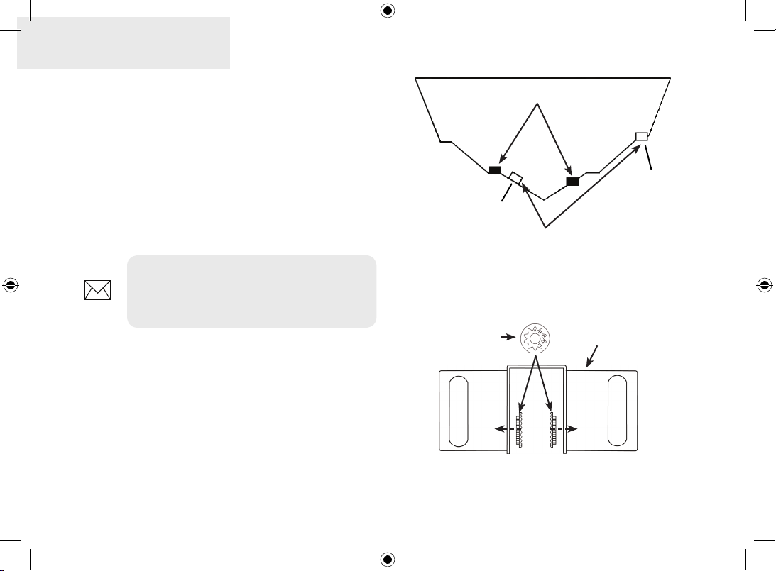
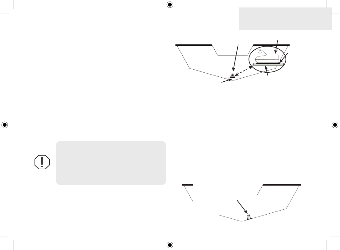
A. Select a transducer location
To function properly the Skimmer transducer must
be in the water at all times and in a location that has
a smooth ow of water when the boat is moving.
If the transducer is not placed in a smooth ow
of water, interference caused by bubbles and
turbulence may show on-screen as random lines or
dots. The unit also could lose bottom signal when
the boat is on plane.
NOTE: Mount the transducer at least
one foot away from the engine lower
unit.
B. Aligning Ratchets on bracket
You will use the ratchets to ensure the transducer is installed parallel to the ground.
1. Insert the ratchets in the bracket with the
letter “A” aligned with the dot stamped
on the outside of the transducer bracket.
Good locations
Too high
Poor angle
Poor locations
2. Slide the transducer into the bracket
and temporarily slide the bolt through
the transducer bracket.
Ratchet
Bracket
2
0.TWEETY INSTALL_SONAR_DSI.indd 2 9/14/2011 11:55:30 PM
Page 3
Traditional Sonar
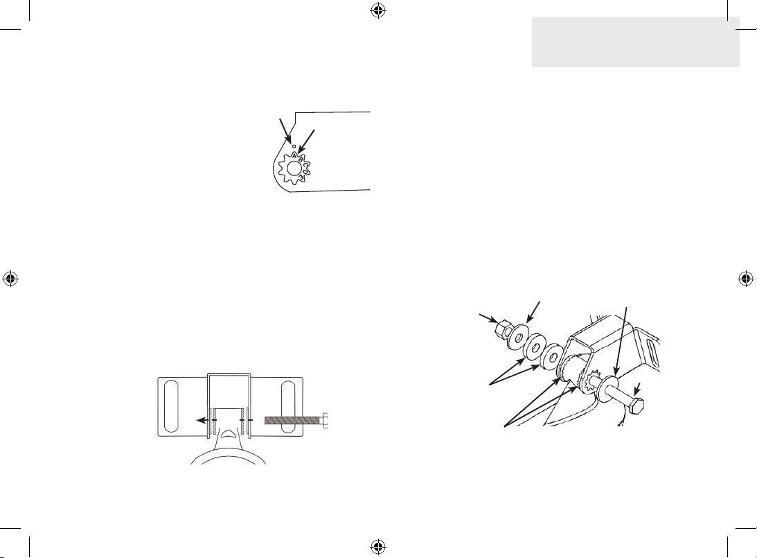
3. Hold the transducer
assembly against
the transom. Look at
the transducer from
Align dot and
letter "A".
dot
A
the side. If it is parallel to the ground,
then the “A” position
is correct.
4. If the transducer can not be adjusted
so its face is parallel to the ground, remove the transducer and ratchets from
the bracket. Reinsert the ratchets into
the bracket, this time with the letter “B”
aligned with the dot stamped in the
bracket. Reassemble the transducer
and bracket and place it against the
transom.
5. Check to see if the transducer will adjust so its face is parallel with the ground.
Repeat this process until the transducer can
be adjusted so its face is parallel with the
ground.
C. Assembling the bracket
After determining the correct position for the
ratchets, loosely assemble the transducer and
bracket assembly.
Lock nut
Metal washer
Rubber washers
Ratchets
Metal washer
Bolt
3
0.TWEETY INSTALL_SONAR_DSI.indd 3 9/14/2011 11:55:31 PM
Page 4
Traditional Sonar
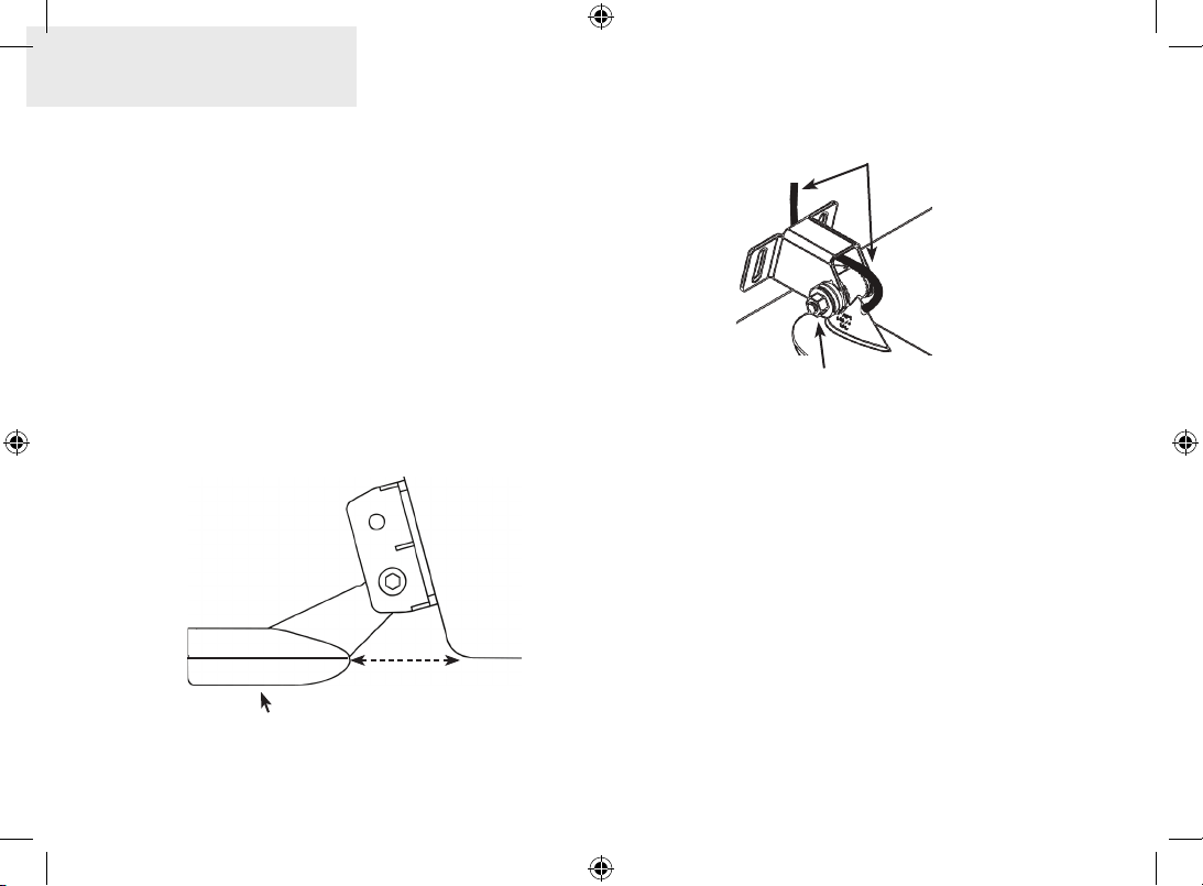
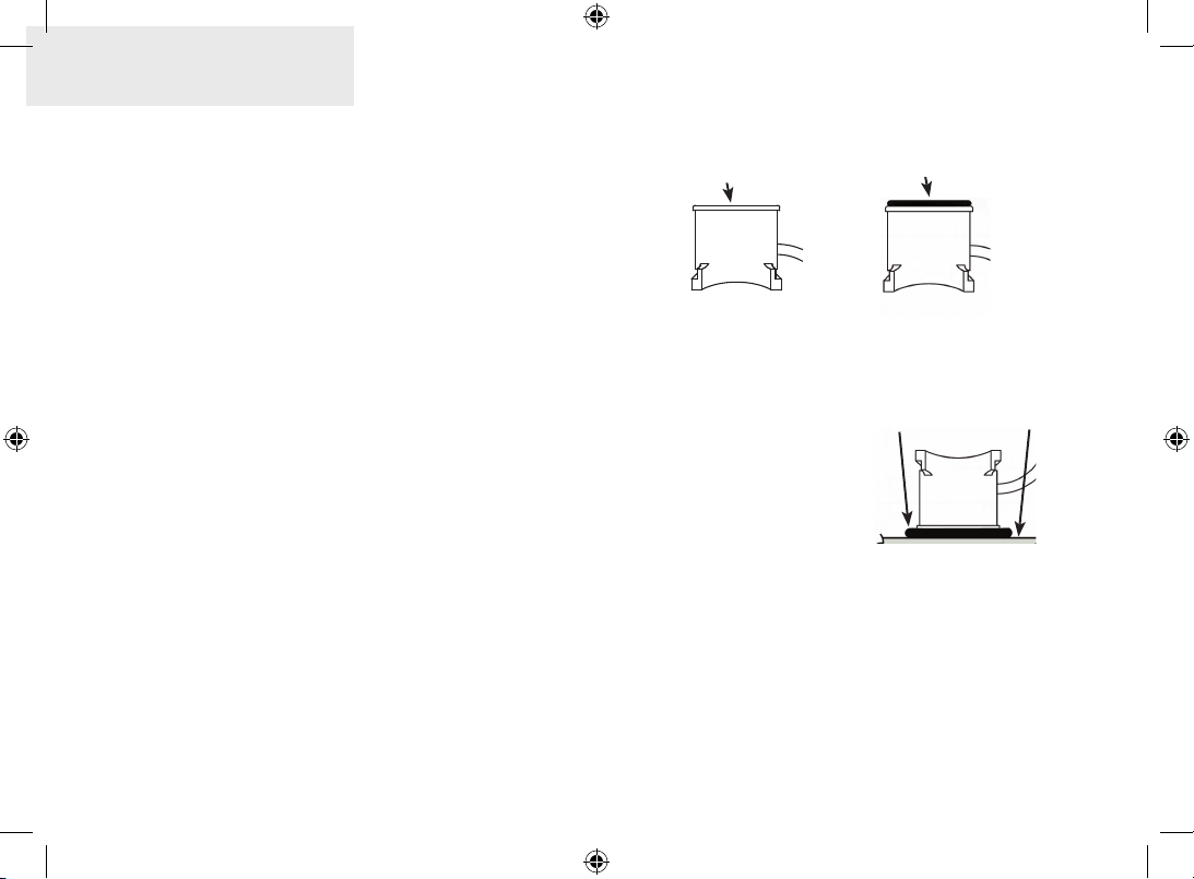
D. Attaching Transducer to Transom
1. Adjust the transducer so its face is
parallel with the ground and its center
line is even with the bottom of the boat
hull.
2. Hold the transducer and bracket
assembly against the transom. When the
transducer and bracket are properly aligned
mark its position on the hull.
3. Drill the mounting holes for the transducer
bracket. Use a #29 bit (for the #10 screws).
Transom
Bottom of
Transducer face must be
parallel with the ground
hull
Run the cable over
the bolt and through
the bracket.
Do not over tighten the lock nut;
otherwise transducer may not kick-
up if it strikes an object.
Routing cables
When mounting your transducer, make sure to
leave some slack in the cable near the transducer. If
you need to drill a hole in the transom to pass the
connector through, the hole size will depend on
the connector on the end of the transducer’s cable.
E. Make test run to determine results
After the transducer is installed make a test run to
ensure the transducer is installed properly. Use the
4
0.TWEETY INSTALL_SONAR_DSI.indd 4 9/14/2011 11:55:31 PM
Page 5
Traditional Sonar
slots in the transducer mounting bracket to loosen
the screws and slide the transducer up or down, if
adjustments are necessary.
Shoot-thru-hull Skimmer and
Pod transducer installation
Before attempting any installation on boats with
otation material sandwiched within the hull, consult the boat manufacturer. In a shoot-thru-hull installation the transducer is epoxied to the inside of
the boat hull.
WARNING: Do not remove material
from the inner hull. Careless grinding
on the hull could damage hull integrity.
Contact the boat dealer or manufacturer
to conrm hull specications
A transducer can not shoot through wood or metal
hulls. Wood and metal hulls require either a transom mount or thru-hull installation. For shootthru-hull applications many boat hulls have a at
.
Transducer epoxied to hull
Keel pad
Transducer
Epoxy
Hull
keel pad that oers a good transducer mounting
surface.
Make sure the Skimmer transducer is oriented so
the nose of the transducer is facing the bow (front)
of the boat. If the transducer has a built in temp
sensor, it will only show the temperature of the
hull, not the water temp.
Before you epoxy the transducer to the hull, make
sure the area is clean, dry and free of oil or grease.
The surface of the hull must be at so the entire
On vee hulls
try to place the
transducer where
the dead rise is
10° or less.
5
0.TWEETY INSTALL_SONAR_DSI.indd 5 9/14/2011 11:55:31 PM
Page 6
Traditional Sonar
transducer face is in contact with the hull. Also, make
sure the cable is long enough to reach the sonar unit.
To use shoot-thru-hull installation:
1. Sand the inside surface of the hull, where
the transducer is to be epoxied, and the
face of the transducer. Sand the hull until
it is smooth to the touch. The sanded
area should be about 1-1/2 times the
diameter of the transducer.
2. After sanding, clean the hull and the face
of the transducer with an alcohol wipe to
remove any dust.
3. Apply a thin layer of epoxy (about 1-16”
or 1.5 mm) on the face of the transducer
and the sanded area on the hull. Be
careful when mounting a transducer
inside a boat hull. Once epoxied into
position, the transducer can be very
difcult to remove. Epoxy is available
at www.lei-extras.com (Part No. 106-
98).
Sand transducer face
and mounting location
Apply epoxy to transducer
face and mounting location.
4. Press the transducer into the epoxy,
turning it to force out any air bubbles from
under the transducer face. Make sure
there are no
air pockets
HullEpoxy
in the epoxy
layers.
5. Stop pressing
when it bottoms
out on the hull.
Epoxy transducer to hull.
Apply pressure to hold the transducer in
place while the epoxy sets. Be careful not
to move the transducer while the epoxy
is setting. Allow the epoxy to set before
moving the boat.
6
0.TWEETY INSTALL_SONAR_DSI.indd 6 9/14/2011 11:55:32 PM
Page 7
Traditional Sonar
6. When nished, the face of the
transducer should be parallel with the
hull with a minimum amount of epoxy
between the hull and transducer.
Trolling motor Skimmer and
Pod Installation
The TMB-S trolling motor bracket (Part No. 51-45) is
an optional accessory and is available through LEI
Extras at www.lei-extras.com. The TMB-S bracket
is used to attach a one-piece bracket skimmer
transducer to a trolling motor. The Pod transducer
does not need a TMB-S trolling motor bracket to be
installed on a trolling motor. It only needs a hose
clamp (adjustable strap).
The top of the Pod
transducer is curved to t
the contour of the trolling
motor, so you do not
need a TMB-S mounting
bracket.
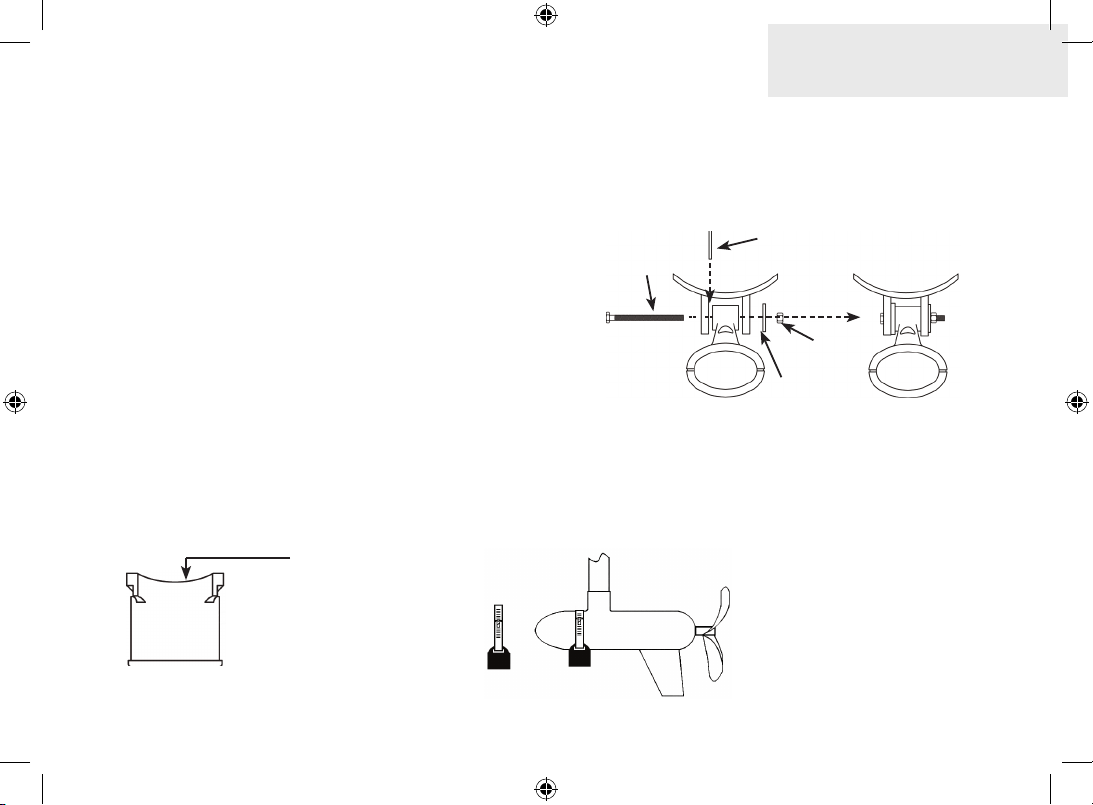
Installing transducer on trolling motor:
1. Attach the skimmer transducer to the
bracket as shown in the diagram.
Internal tooth
washer
Bolt
Flat washer
Plastic bracket
Lock
nut
2. Slide the adjustable strap (hose clamp)
through the plastic bracket on the
skimmer transducer or through the Pod
transducer slots and then slip the strap
around the trolling motor.
Position the transducer
to so its face is pointing
straight down when the
trolling motor is in the
water.
7
0.TWEETY INSTALL_SONAR_DSI.indd 7 9/14/2011 11:55:32 PM
Page 8
Traditional Sonar
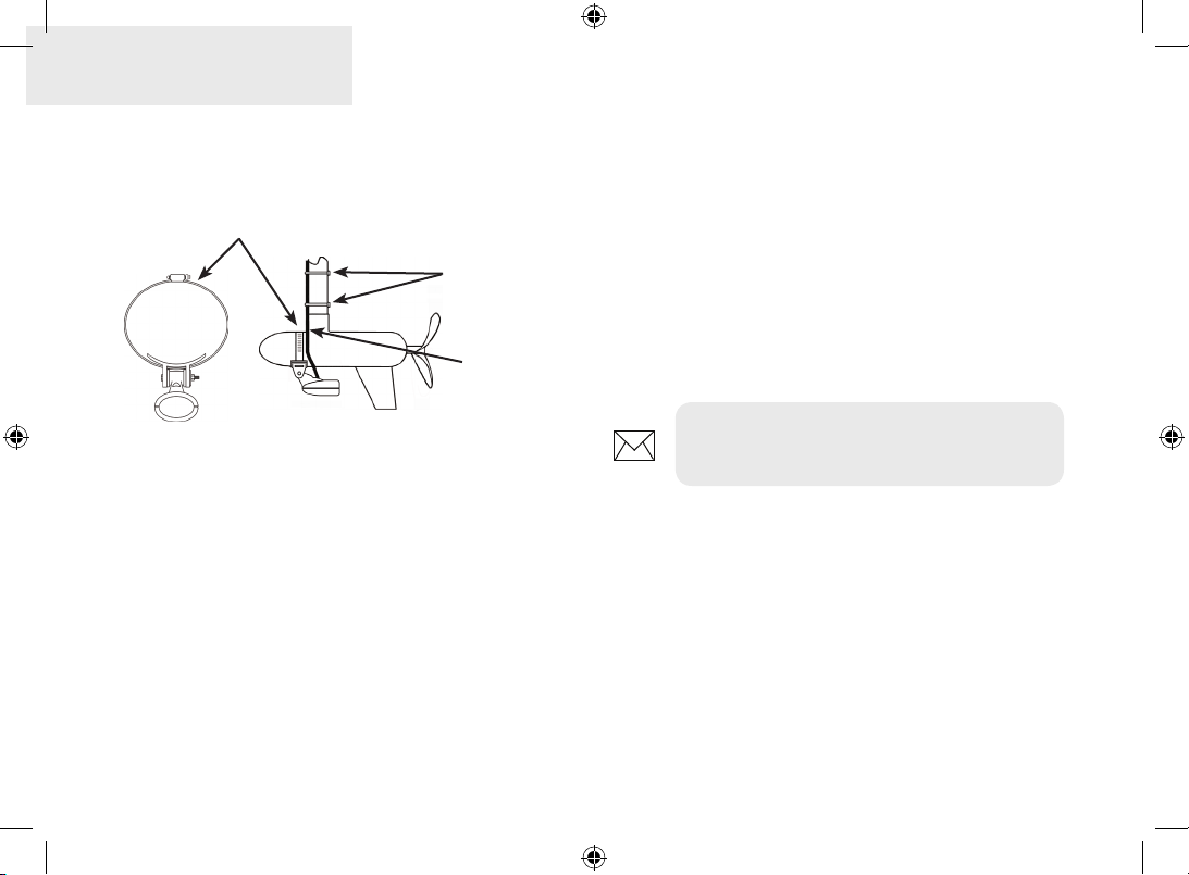
3. Position the transducer so its face is
pointing straight down when the trolling
motor is in the water.
Adjustable strap
Plastic ties (not
included)
Transducer
cable
4. Tighten the adjustable strap securely
to the trolling motor. Make sure there is
enough slack in the transducer cable for
the trolling mount to turn freely.
Connecting the unit to power
1. Connect the black wire to a ground.
2. Attach a 3 Amp fuse (not included) to
the end of the power wire and then connect the fuse to the positive (+) terminal
on the battery.
3. Connect the Power cable to the Power
port on the back of the display unit.
NOTE: Use 18 gauge wire to extend the
power or ground wires.
8
0.TWEETY INSTALL_SONAR_DSI.indd 8 9/14/2011 11:55:32 PM
Page 9

Power
port
Traditional Sonar
External GPS port
Red (power)
wire
3 Amp
fuse (not
included)
Black (ground)
wire
12V
Optional paddlewheel
speed/temp sensor
Speed/temp port;
also used for NMEA
0183
Optional temp
sensor
9
0.TWEETY INSTALL_SONAR_DSI.indd 9 9/14/2011 11:55:34 PM
Page 10

Traditional Sonar
NMEA 0183 Connection Diagram
(GPS capable units only)
Temp /Speed port
NMEA0183
NDC-4
Optional NMEA
0183 cable
Yellow TX NMEA IN (+)
Shield (ground) NMEA IN (-)
10
0.TWEETY INSTALL_SONAR_DSI.indd 10 9/14/2011 11:55:35 PM
Page 11

Display unit
Mounting the display unit
Before mounting the display unit mount, make sure there is nothing in the area that will obstruct the
display unit when it is installed on the bracket.
To install bracket mount:
1. Place the bracket on the desired mounting surface and mark the four mounting holes. If
you want to run the unit’s cables up through the mounting surface, make a mark in the
center of the bracket mounting surface.
2. Drill pilot holes for the four mounting holes. If desired, use a 1-inch (25mm) bit to drill the
center cabling hole in the mounting surface.
3. If you are running the cables up through the mounting surface, push the cables through the
mounting surface and then pull them through the cabling hole in the center of the bracket.
4. Align the mounting bracket with the four mounting holes and use the supplied screws to
fasten it to the mounting surface.
5. Connect the display unit to the bracket mount.
11
0.TWEETY INSTALL_SONAR_DSI.indd 11 9/14/2011 11:55:35 PM
Page 12

Display unit
Removing the unit from the bracket
12
0.TWEETY INSTALL_SONAR_DSI.indd 12 9/14/2011 11:55:40 PM
Page 13
DSI Sonar
DSI Series Installation
This document covers the installation of the DSI series transducer and display unit installation.
WARNING: Make sure you read all installation instructions before drilling holes in
your vessel.
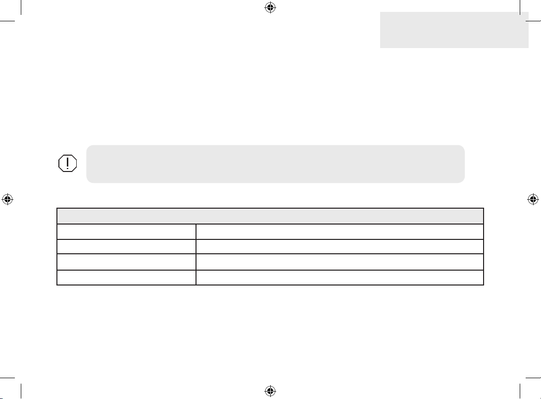
(Tools and Supplies — not included)
Drill Marine grade below waterline sealant
1” (25mm) or 5/8” (15mm) drill bit Zip ties (trolling motor mount)
#29 (0.136”) (3mm) drill bit Trolling motor accessory kit
Slotted-head (Phillips) drill bit FM-ME5 ush mount kit (pn: 000-10028-001) (optional)
13
0.TWEETY INSTALL_SONAR_DSI.indd 13 9/14/2011 11:55:41 PM
Page 14

DSI Sonar
Transducer
Bolt
Transducer bracket assembly
Rubber
washer
Metal
washer
Ratchets
Metal
washer
Rubber
washer
Transducer
bracket
Nut
14
0.TWEETY INSTALL_SONAR_DSI.indd 14 9/14/2011 11:55:41 PM
Page 15
Aligning transducer ratchets
DSI Sonar
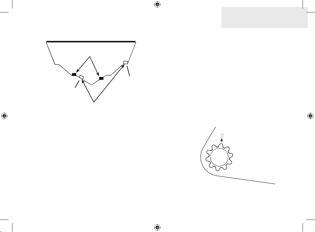
Good location
Too high
Poor angle
Poor location
Selecting transducer location
The DSI transducer must be in the water at all times
and in a location that has a smooth ow of water
when the boat is moving.
If it is not placed in a smooth ow of water,
interference from bubbles and turbulence may
diminish product performance. The unit also could
lose bottom signal when the boat is on plane.
Install the transducer at least 1’ (.3m) away from
the engine’s lower unit.
Ratchets are used to ensure the transducer is
installed parallel to the ground.
1. Insert the ratchets in the bracket with
the letter “A” aligned with the dot
stamped on the outside of the transducer bracket.
2. Slide the transducer into the bracket
and temporarily slide the bolt through
the transducer bracket.
A
B
C
D
E
15
0.TWEETY INSTALL_SONAR_DSI.indd 15 9/14/2011 11:55:41 PM
Page 16

DSI Sonar
3. Hold the transducer assembly against
the transom. Look at the transducer from the side. If it is parallel to the
ground, then the “A” position is correct.
4. If the transducer can not be adjusted
so its face is parallel to the ground, remove the transducer and ratchets from
the bracket. Reinsert the ratchets into
the bracket, this time with the letter “B”
aligned with the dot stamped in the
bracket. Reassemble the transducer
and bracket and place it against the
transom.
5. Repeat this process until the transducer
can be adjusted so its face is parallel
with the ground.
Mounting to transom
1. Adjust the transducer so its face is parallel with the ground and its center is
even with the bottom of the boat hull.
2. Hold the transducer and bracket assembly against the transom. When the
transducer and bracket are properly
aligned mark its position on the hull.
16
0.TWEETY INSTALL_SONAR_DSI.indd 16 9/14/2011 11:55:42 PM
Page 17
3. Drill the mounting holes for the transducer bracket. Use a #29 bit (for the
#10 screws).
4. Attach the transducer to the transom
using the supplied screws (2).
Shoot-thru hull
The DSI transducer can be epoxied to the hull for
shoot-thru installations. This is not a recommended
installation method since it signicantly degrades
DSI performance.
Mounting on trolling motor
The optional DSI trolling motor accessory (pn: 00010261-001) is available through LEI Extras at www.
lei-extras.com. The Trolling motor accessory allows
you to mount the DSI transducer to a trolling motor.
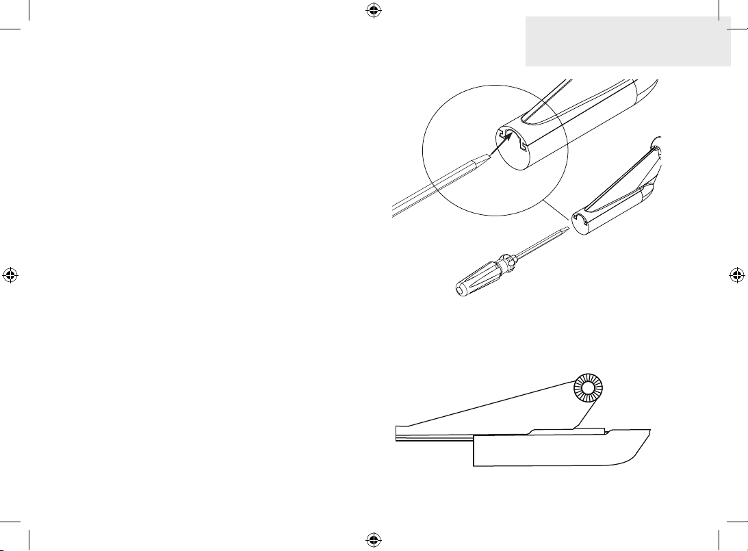
You must remove the factory installed transducer
mount from the transducer housing before you
can install the DSI transducer on a trolling motor.
DSI Sonar
Using a athead screwdriver, depress the release
tab and slide o the transducer mount.
17
0.TWEETY INSTALL_SONAR_DSI.indd 17 9/14/2011 11:55:43 PM
Page 18

DSI Sonar
Installing transducer on trolling motor:
1. Place the DSI transducer inside the
trolling motor housing.
2. Slide the adjustable strap (hose clamp)
through the slots in the trolling motor
housing and slip the strap around the
trolling motor.
Slide the adjustable
strap through these slots.
3. Position the trolling motor housing so its
face is pointing down when the trolling
motor is in the water.
4. Tighten the adjustable strap securely
to the trolling motor. Make sure there is
enough slack in the transducer cable for
the trolling motor to turn freely.
18
0.TWEETY INSTALL_SONAR_DSI.indd 18 9/14/2011 11:55:43 PM
Page 19

DSI Wiring Diagram
Fuse (not
included)
Battery
DSI lter cable
Transducer/
power cable
Optional
speed
sensor
DSI Sonar
Optional
temp
sensor
DSI transducer
19
0.TWEETY INSTALL_SONAR_DSI.indd 19 9/14/2011 11:55:44 PM
Page 20

NMEA 0183 Connection Diagram
(GPS capable units only)
Temp /Speed port
NMEA0183
NDC-4
Optional NMEA
0183 cable
Yellow TX NMEA IN (+)
Shield (ground) NMEA IN (-)
0.TWEETY INSTALL_SONAR_DSI.indd 20 9/14/2011 11:55:45 PM
Page 21

0.TWEETY INSTALL_SONAR_DSI.indd 21 9/14/2011 11:55:45 PM
Page 22

Visit our website:
www.lowrance.com
Copyright © 2011
*988-10169-001*
0.TWEETY INSTALL_SONAR_DSI.indd 22 9/14/2011 11:55:45 PM
All Rights Reserved
Navico Holding AS
 Loading...