

Page 1
Elite 5 Sonar/GPS & Elite 5m GPS
Installation & Operation
manual
Installation & Operation manual
Page 2

Copyright © 2009 Navico
All rights reserved.
Lowrance® and Navico® are registered trademarks of Navico.
Fishing Hot Spots® is a registered trademark of Fishing Hot Spots Inc.
Navionics® is a registered trademark of Navionics, Inc.
Points of Interest Data in this unit are by infoUSA, copyright© 2001-2008, All Rights Reserved.
infoUSA is a trademark of infoUSA, Inc.
Additional mapping data: Copyright© 2008 by Maptech Inc.
Navico may nd it necessary to change or end our policies, regulations and special offers at any time. We reserve the
right to do so without notice. All features and specications subject to change without notice.
Visit our website:
www.lowrance.com
Navico
12000 E. Skelly Dr.
Tulsa, OK USA 74128-2486
Page 3

Table of Contents
Installation ...............................................2
Basic Operation ....................................12
Menu operation............................................. 13
Fishing Mode (Elite 5 only) ........................... 15
Advanced Mode............................................ 16
Restore defaults ........................................... 16
Pages .....................................................17
Steer Page.................................................... 17
Sonar Page................................................... 17
Chart Page ................................................... 18
Overlay Data................................................. 19
Sonar Operation: Elite 5.......................20
Viewing Sonar History .................................. 20
Sensitivity .................................................... .21
Depth Range ............................................... .22
Frequency.................................................... .23
Sonar Options menu.................................... .23
Chart Operation ....................................25
Waypoints, Routes, Trails ............................. 26
Creating a route ........................................... .27
Navigating a route ....................................... .29
To cancel navigation: ................................... .30
Creating trails .............................................. .31
Navigating a trail .......................................... .32
Settings Menu .......................................34
System.......................................................... 34
Navigation..................................................... 36
Sonar ........................................................... 38
Installation menu .......................................... 39
Alarms ......................................................... 40
Units ............................................................ .40
Simulator (Advanced Mode) ........................ .40
Index ......................................................41
Specications .......................................42
1
Page 4
Installation
Elite Series Installation
This document covers the installation of the transducer and display unit installation,
which includes connecting the unit to power and installing the unit on the bracket
mount. Make sure you read all the installation instructions before drilling holes
in your vessel.
NOTE: This majority of this installation does not apply to the Elite 5m since it does not
have a transducer. Turn to pages 9-11 for information on mounting the display unit and
connecting the unit to power.
Transducer Installation
One piece bracket (Recommended Tools and Supplies — not included)
Drill Marine grade above-or-below waterline sealant
1” (25mm) or 5/8” (15mm) drill bit Marine grade epoxy (Shoot-thru-hull install only)
#29 (0.136”) (3mm) drill bit Zip ties (trolling motor mount)
Phillips (Slotted-head) screwdriver TMB-S bracket kit (Skimmer trolling motor mount)
2
Page 5
Installation
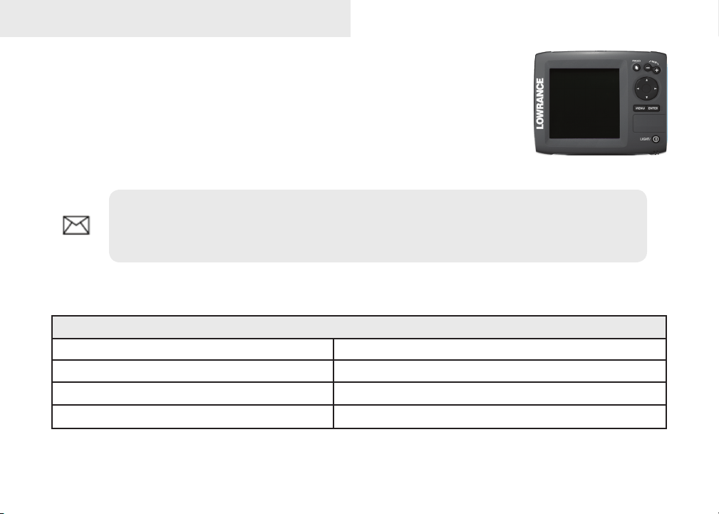
A. Select a transducer location
To function properly the Skimmer transducer must be in the
water at all times and in a location that has a smooth ow of
water when the boat is moving.
If the transducer is not placed in a smooth ow of water,
interference caused by bubbles and turbulence may show
on-screen as random lines or dots. The unit also could lose
bottom signal when the boat is on plane.
NOTE: Mount the transducer at least one foot away from the engine lower unit.
B. Aligning Ratchets on Transducer bracket
You will use the ratchets to ensure the
transducer is installed parallel to the
ground.
Insert the ratchets in the 1.
bracket with the letter “A”
aligned with the dot stamped
on the outside of the
transducer bracket.
Ratchet
3
Bracket
Good locations
Poor locations
Align dot and
letter "A".
dot
A
Page 6
Installation
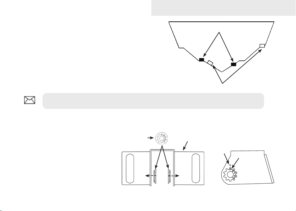
Slide the transducer into the bracket and temporarily slide 2.
the bolt through the transducer bracket.
Hold the transducer assembly against the transom. Look at 3.
the transducer from the side. If it is parallel to the ground,
then the “A” position is correct.
If the transducer can not be adjusted so its face is parallel 4.
to the ground, remove the transducer and ratchets from
the bracket. Reinsert the ratchets into the bracket, this time
with the letter “B” aligned with the dot stamped in the bracket. Reassemble the transducer
and bracket and place it against the transom.
Check to see if the transducer will adjust so its face is parallel with the ground. Repeat this 5.
process until the transducer can be adjusted so its face is parallel with the ground.
C. Assembling the Transducer bracket
After determining the correct position for the ratchets,
loosely assemble the transducer and bracket assembly.
Lock nut
Rubber washers
Ratchets
Metal washer
Metal washer
Bolt
4
Page 7
Installation
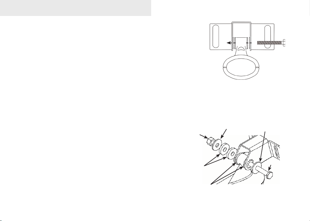
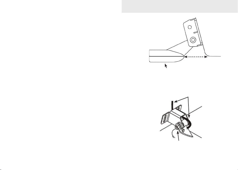
D. Attaching the Transducer to the Transom
Adjust the transducer so its face is parallel with the 1.
ground and its center line is even with the bottom of
the boat hull.
Hold the transducer and bracket assembly against 2.
the transom. When the transducer and bracket are
properly aligned mark its position on the hull.
Drill the mounting holes for the transducer bracket. 3.
Use a #29 bit (for the #10 screws).
Routing cables
When mounting your transducer, make sure to leave some slack
in the cable near the transducer. If you need to drill a hole in the
transom to pass the connector through, the hole size will depend
on the connector on the end of the transducer’s cable.
E. Make a test run to determine the results
After the transducer is installed make a test run to ensure the
transducer is installed properly. Use the slots in the transducer
mounting bracket to loosen the screws and slide the transducer up
or down, if adjustments are necessary.
5
Transom
Bottom of
Transducer face must be
parallel with the ground
Run the cable over
the bolt and through
the bracket.
Do not over tighten the lock nut;
otherwise transducer may not kick-
up if it strikes an object.
hull.
Page 8
Installation
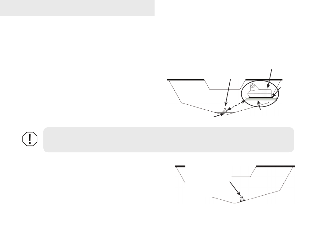
Shoot-thru-hull Skimmer and Pod transducer installation
Before attempting any installation on boats with otation material sandwiched within the hull, consult the
boat manufacturer. In a shoot-thru-hull installation the transducer is epoxied to the inside of the boat hull.
A transducer can not shoot through wood or metal hulls. Wood and metal hulls require either a transom mount
or thru-hull installation. For shoot-thru-hull applications
many boat hulls have a at keel pad that offers a good
transducer mounting surface.
Make sure the Skimmer transducer is oriented so the
nose of the transducer is facing the bow (front) of the
boat. If the transducer has a built in temp sensor, it
will only show the temperature of the hull, not the water
temp.
WARNING: Do not remove material from the inner hull. Careless grinding on the hull could
damage hull integrity. Contact the boat dealer or manufacturer to conrm hull specications
Transducer epoxied to hull
Keel pad
Transducer
Hull
Epoxy
.
Before you epoxy the transducer to the hull, make sure the
area is clean, dry and free of oil or grease.
The surface of the hull must be at so the entire transducer
face is in contact with the hull. Also, make sure the cable is
long enough to reach the sonar unit.
6
On vee hulls
try to place the
transducer where
the dead rise is
10° or less.
Page 9

To use shoot-thru-hull installation:
Sand the inside surface of the hull, where the transducer is to be epoxied, and the face of 1.
the transducer. Sand the hull until it is smooth to the touch. The sanded area should be
about 1-1/2 times the diameter of the transducer.
2. After sanding, clean the hull and the face of the transducer
with an alcohol wipe to remove any dust.
Apply a thin layer of epoxy (about 1-16” or 1.5 mm) on the 3.
face of the transducer and the sanded area on the hull. Be
careful when mounting a transducer inside a boat hull.
Once epoxied into position, the transducer can be very
difcult to remove.
Press the transducer into the epoxy, turning it to force out any 4.
air bubbles from under the transducer face. Make sure there
are no air pockets in the epoxy layers.
Installation
Sand transducer face
and mounting location
Apply epoxy to transducer
face and mounting location.
Stop pressing when it bottoms out on the hull. Apply pressure 5.
to hold the transducer in place while the epoxy sets. Be careful
not to move the transducer while the epoxy is setting. Allow
the epoxy to set before moving the boat.
When nished, the face of the transducer should be parallel 6.
with the hull with a minimum amount of epoxy between the
hull and transducer.
7
HullEpoxy
Epoxy transducer to hull.
Page 10
Installation
Trolling motor Skimmer and Pod Installation
The TMB-S trolling motor bracket (Part No. 51-45) is an optional accessory and is available through LEI
Extras at www.lei-extras.com. The TMB-S bracket is used to attach a one-piece bracket skimmer transducer
to a trolling motor. The Pod transducer does not need a TMB-S trolling motor bracket to be installed on a
trolling motor. It only needs a hose clamp (adjustable strap).
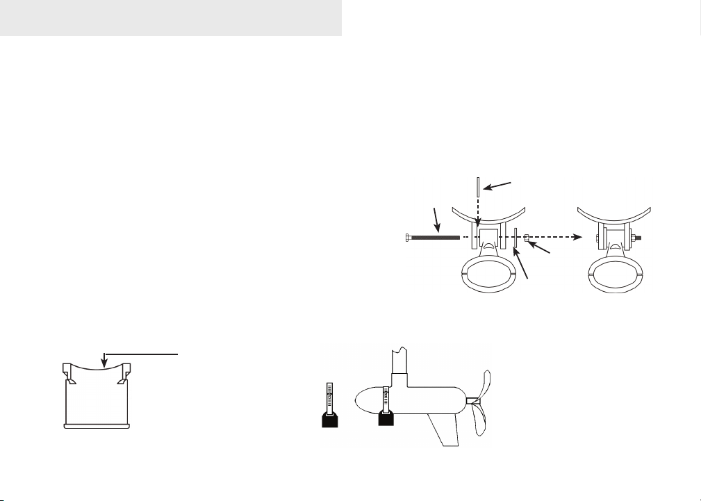
Installing transducer on trolling motor:
Using the components supplied with the TMB-S 1.
bracket attach the skimmer transducer to the
bracket as shown in the diagram.
Slide the adjustable strap (hose clamp) through 2.
the plastic bracket on the skimmer transducer or
through the Pod transducer slots and then slip
the strap around the trolling motor.
Position the transducer so its face is pointing straight down when the trolling motor is in 3.
the water.
The top of the Pod
transducer is curved to t
the contour of the trolling
motor, so you do not
need a TMB-S mounting
bracket.
Bolt
Internal tooth
washer
Plastic bracket
Lock
nut
Flat washer
Position the transducer
to so its face is pointing
straight down when the
trolling motor is in the
water.
8
Page 11
Installation
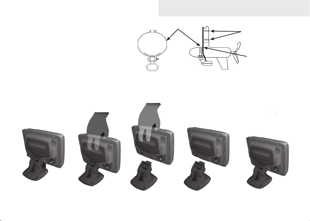
Tighten the adjustable strap 4.
securely to the trolling motor.
Make sure there is enough slack
in the transducer cable for the
trolling motor to turn freely.
Adjustable strap
Plastic ties (not
included)
Transducer
cable
Mounting display unit
Before mounting the display unit mount, make sure there is nothing in the area that will obstruct the display
unit when it is installed on the bracket.
9
Page 12

Installation
To install bracket mount:
Place the bracket on the desired mounting surface and mark the four mounting holes. If 1.
you want to run the unit’s cables up through the mounting surface, make a mark in the
center of the bracket mounting surface.
Drill pilot holes for the four mounting holes. If desired, use a 1-inch (25mm) bit to drill the 2.
center cabling hole in the mounting surface.
If you are running the cables up through the mounting surface, push the cables through the 3.
mounting surface and then pull them through the cabling hole in the center of the bracket.
Align the mounting bracket with the four mounting holes and use the supplied screws to 4.
fasten it to the mounting surface.
Connect the display unit to the bracket mount. 5.
Connecting to Power
Connect the black wire to a ground. 1.
Attach a 3 Amp fuse to the end of the power wire and then connect the fuse to the positive 2.
(+) terminal on the battery.
Connect the Power cable to the Power port on the back of the display unit. 3.
NOTE: Use 18 gauge wire to extend the power or ground wires.
10
Page 13
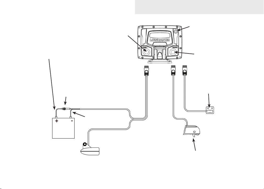
Power
port
Installation
External GPS port
Red (power)
wire
3 Amp
fuse
12V
Speed/temp port;
also used for NMEA
0183
Optional temp
sensor
Black (ground)
wire
Optional paddlewheel
speed/temp sensor
11
Page 14
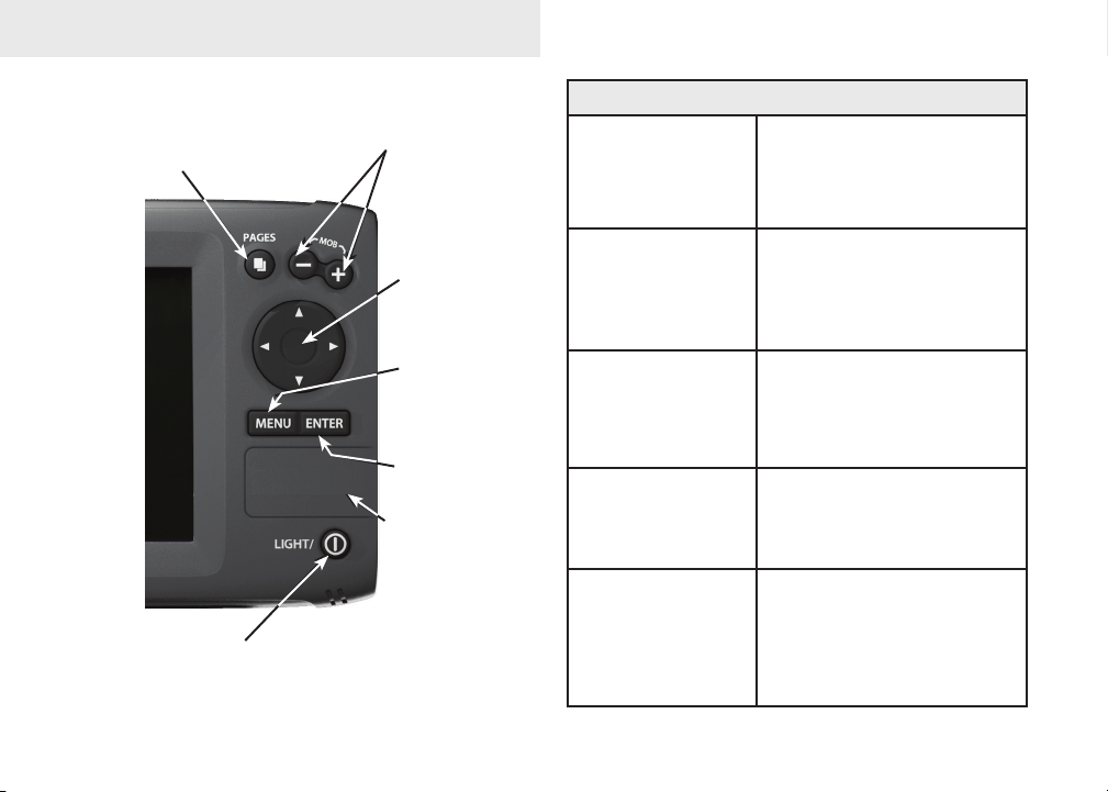
Basic Operation
PAGES: Opens
pages menu;
allows you to
select a page to
view
LIGHT/POWER: controls
backlight level and turns
unit on/off
ZOOM Keys: used to zoom in/zoom
out; press and hold both keys to
create Man Overboard waypoint
KEYPAD:
controls cursor &
selects items on
menus
MENU: Opens
settings, context
and page menus
ENTER: nalizes
menu selections;
save waypoint at
cursor position
microSD CARD
SLOT: insert
microSD card here
Getting Started
Turn unit on/off
Man Overboard
waypoint
Adjusting
the backlight
Muting Audio
Selecting a
GPS Source
To turn on/off the unit,
press and hold the LIGHT/
POWER key for three
seconds.
Press the zoom in and zoom
out keys at the same time
to set a Man Overboard
waypoint at your location.
This unit has
11 backlight
levels. Press the LIGHT/
POWER key to switch
backlight levels.
Select Mute Audio from the
System menu and press
ENTER.
Select
GPS Source from the
System menu and press
ENTER. Select internal
or
external and press
ENTER.
12
Page 15
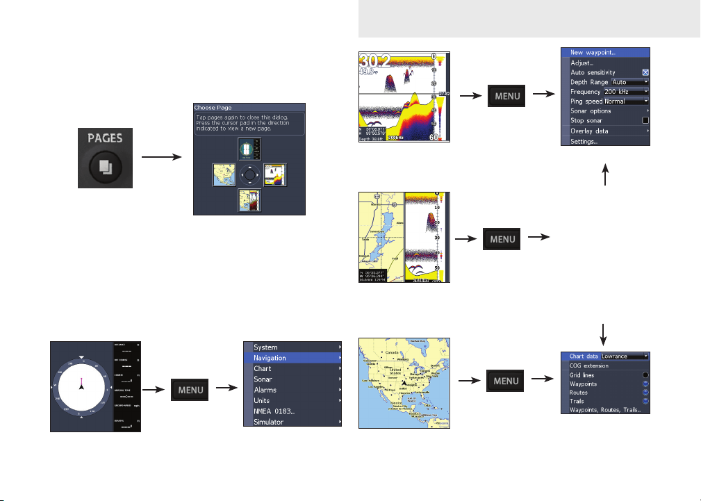
Menu operation
This unit has four page screens: Steer, Sonar, Chart/
Sonar and Chart.
Basic Operation
Pages menu
Page context menus
The Sonar, Chart/Sonar and Chart pages have menus
that can only be accessed when those pages are
displayed.
Steer page
Settings menu
Sonar Page
(Elite 5 only)
Chart/Sonar page
(Elite 5 only)
Chart page
13
Sonar menu
Chart or sonar
menu will appear
depending on
which panel is
active. Press
the
PAGES key
twice to switch
active panels.
Chart menu
Page 16
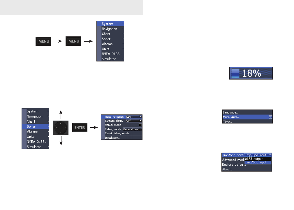
Basic Operation
Making adjustments
There are several menu types used to make
adjustments to options and settings, including
scrollbars, on/off features and dropdown menus.
Settings menu
Accessing menu items
The keypad and ENTER key are used to select
menu items and open submenus. Use the keypad to
highlight the desired item and press ENTER.
Scrollbars
Select the scrollbar and press
the keypad left (decrease) or
right (increase).
On/Off features
Select an on/off menu item
and press ENTER to turn it
on/off.
Dropdown menus
Press the keypad up/down
to select the desired item
and press ENTER.
14
Page 17

Basic Operation
Entering text
Some functions, like naming a waypoint, route or
trail, will require you to input text.
Switches letters
to uppercase/
lowercase
Switches
keyboard between
Alpha and
QWERTY layout
To input text:
Use the keypad to select the desired 1.
character and press ENTER.
Repeat Step 1 for each character. 2.
When entry is completed, highlight 3. OK
and press ENTER.
Exiting menus
If a screen or menu has an exit option (Close, Return
to screen, Exit dialog) highlight the exit option and
press ENTER to exit.
If there is no exit option press the MENU
key repeatedly to close all menus.
Fishing Mode
Fishing modes enhance
the performance of your
unit by providing preset
packages of sonar settings
geared to specic shing
conditions (Elite 5 only).
NOTE: Use Shallow Water mode when
shing in less than 100 feet of water;
otherwise your unit may not track bottom
properly.
15
Page 18

Basic Operation
Fishing Mode Options
General
Use
Shallow
Water
Fresh
Water
Deep
Water
Slow
Trolling
Fast
Trolling
Clear
Water
Brackish
Water
Bottom brown/blue background; 50% ping
speed
Bottom brown/white background; best for depths
less than 100 feet
Bottom brown/white background; 50% ping
speed
Deep Blue; 50% ping speed; 50kHz is primary
transducer frequency
Bottom brown/white background; 50% ping
speed
Bottom brown/white background; slightly lower
chart speed
Bottom brown/white background; 50% ping
speed
Bottom brown/blue background; higher ASP;
slightly lower chart speed
Cursor
The keypad moves the cursor around the display,
allowing you to scroll the map, select map items and
review sonar history (Elite 5 only). Press MENU
and select Return to vessel to clear the cursor.
Advanced Mode
Enables advanced features
and settings.
Advanced Mode features
Colorline Enables manual control of colorline
Surface Clarity Enables control of surface clarity
Ping Rate Enables manual control of ping rate
Alarms
NMEA 0183 Enables NMEA 0183 interface
Units
Enables Arrival, Off Course and Anchor
alarms
Enables Distance, Speed, Depth,
Temperature and Bearings
Restore defaults
Resets unit options and
settings to defaults.
16
Page 19

Pages
CompassDirection to
Navigation
information
waypoint
Your location
Current Track
Steer Page
The Steer page has a compass that shows your current
track, the direction to your destination, and a digital
data navigation panel.
Overlay Data
Location and depth
Surface Clutter
Fish arches
Frequency
Colorline
Range Scale
Amplitude Scope
Cursor
Depth
Sonar Page
Displays the water column moving from right to left
on your unit’s screen. On the right side of the screen,
the Amplitude Scope bar previews echoes about to
appear on the display.
17
Page 20

Pages
Chart/Sonar Page
Chart/Sonar page (Elite 5 only)
Consists of a chart/sonar splitscreen. Press the
PAGES key twice to switch active panels.
Depth contours
Current location;
distance to destination
Current location
Waypoint
Zoom
Range
Chart Page
Consists of map that moves in real-time as you move.
By default, the map is shown from a birds-eye view
with North at the top of the screen.
18
Page 21

Pages
Overlay Data
Displays selected data on the Sonar, Chart/Sonar and
Chart pages.
To select overlay data:
From a sonar or chart page, press 1.
MENU.
Select 2. Overlay data and press ENTER.
Select 3. Congure and press ENTER.
Press 4. Menu and select Add. Press
ENTER.
Select a category from the Congure 5.
Items to show screen. Press ENTER.
Press 6. MENU and select Return to
overlay.
Press 7. MENU, select Done Conguring
and press ENTER.
Show
Shows/hides selected overlay data on the display.
Customizing Overlay Data
Overlay Data can be resized, moved or removed
from the display from the Overlay data menu.
Press MENU from the Overlay Data screen to access
the menu.
19
Page 22

Sonar Operation: Elite 5
Using your Sonar
This section covers sonar operation, which includes
viewing sonar history and using sonar menus, context menus and submenus. Information is arranged
in the same order as the menus.
Viewing Sonar History
You can review your recent sonar history by moving
the cursor to the left until the screen starts to move
in reverse.
Cursor
Move the blue sonar history bar all the way to the
right to resume normal sonar scrolling.
Press MENU and select Exit cursor mode to remove
the cursor from the screen.
Sonar Menu
The sonar menu has options and
settings that affect the appearance
of the display.
Blue sonar history bar
20
Page 23

Sonar Operation: Elite 5
Adjust
(Advanced Mode)
New Waypoint
Depth Range
Frequency
(Advanced Mode)
Sonar Menu
(Elite 5 only)
Settings
(Advanced mode)
Sonar Options
Overlay
New Waypoint
Places a waypoint at your current position or at the
cursor position. From the new waypoint menu, you
can input a waypoint name, select an icon and input
a desired latitude/longitude.
Waypoint name
keyboard
Lat/Lon window
New waypoint menu
Waypoint icon
menu
Adjust (Advanced Mode only)
Used to make adjustments to
Sensitivity and Colorline.
Sensitivity
Controls the level of detail shown on the display.
Too much detail will clutter the screen. Conversely,
desired echoes may not be displayed if Sensitivity is
set too low.
21
Page 24

Sonar Operation: Elite 5
Auto Sensitivity
Keeps sensitivity at a level that works will under
most conditions, reducing the needs for adjustments.
Auto Sensitivity is turned on by default.
Sensitivity set
to 65 percent.
Sensitivity set
to 85 percent.
Colorline
Separates strong sonar echoes from weak sonar
echoes. That makes it easier for you to distinguish
sh or structure from the bottom. A hard return will
be shown as a wide, bright yellow line, whereas a
soft return will be a narrow reddish-blue line.
Reddish-blue
soft sonar returns
Wide yellow
hard sonar return
NOTE: You can make minor changes to
sensitivity with Auto Sensitivity turned
on. You will have to turn it off to make
signicant adjustments.
Depth Range
Selects the section of the water column
— from surface to bottom — shown on
the display.
Custom Range — Upper and Lower Limits
(Advanced Mode only)
Used to select the upper depth and lower depth of a
desired portion of the water column, allowing you to
select a range that does not include the water surface.
Upper and lower limits must be at least 6.5 ft (2m)
apart.
22
Page 25

Custom range menu
Frequency
Controls the transducer frequency used by the unit.
This unit supports two frequencies:
200kHz and 83kHz.
200 kHz has the highest sensitivity
and best target discrimination in
shallow water. 83 kHz offers a
wider cone angle for more water
coverage.
Sonar Operation: Elite 5
Ping Speed (Advanced Mode only)
Controls the rate the transducer uses to send sonar
waves into the water.
Sonar Options menu
Accesses sonar display settings
and conguration options.
Split Zoom and Split Flasher
Switches the sonar display from full screen sonar to
a split screen view.
Frequency menu
Split frequency sonar view
23
Split Zoom
display
Split Flasher
display
Page 26

Sonar Operation
Color
Allow you to change the look of the display
using palettes with varying degrees of color and
brightness.
Nightview
Amplitude Scope
Displays the amplitude of realtime echoes before they appear
on the display.
Fish ID
Displays sh echoes as sh
symbols instead of arches. Fish
ID is not as effective a sh
nding method as the default sh
arch setting.
Iceview
Ice Mode
Turns on a package of sonar settings that enhance
the performance of your unit when ice shing.
Stop Sonar
Pauses the sonar chart, allowing you to get a closer
look at sonar echoes.
Overlay Data and Settings
Overlay Data is covered in the Basic Operation
section. Settings accesses the Settings menu, but
will only be shown on the map when the unit is in
Advanced mode.
24
Page 27

Using your Chart
Chart Operation
This section covers chart operation, which includes
saving, loading and navigating, waypoints, routes
and trails and using chart menus, context menus and
submenus.
Chart Menu
Accesses Chart settings and
options like map orientation
and waypoints, routes and
trails.
New waypoint
Waypoints,
Settings menu
(Advanced mode)
Chart menu
Routes &
Trails
Orientation
Overlay data
New Waypoint
Creates a waypoint at your current location or at the
cursor position.
When the cursor is on the screen, waypoints will be
saved at the cursor position; conversely, if the cursor
is not displayed onscreen, waypoints will be saved at
your current position.
25
Page 28

Chart Operation
Waypoints, Routes, Trails
Used to create, edit, navigate and delete waypoints,
routes and trails.
Press the keypad left/right to toggle between
waypoint, routes and trails tabs.
Waypoints Screen Waypoints menu
New
Delete
Delete all
Waypoints menu
Save to card
Edit
Allows you to edit the name,
icon and latitude/longitude.
of a selected waypoint.
Edit
Show
Sort
Load from card
26
Page 29

Chart Operation
New
Creates a new waypoint at
the cursor or vessel position.
You can also select waypoint
name, icon and latitude/
longitude from the new
waypoint menu.
Show
Displays the selected waypoint on the
map.
Goto
Allows you to navigate to a waypoint.
Delete and Delete All
Delete is used to delete a
selected waypoint. Delete
All deletes all waypoints.
Sort
Controls how the waypoints list will be
sorted — by name or by nearest.
Routes Screen
Used to create, edit, navigate and delete routes. Use
the keypad to highlight the Routes tab to access the
Routes screen.
Routes screen Routes menu
Creating a route
Routes can be created by inserting waypoints from
the waypoints list or by using the cursor to position
new points on the chart. You can also add waypoints
by selecting existing waypoints from the chart.
27
Page 30

Chart Operation
Shows selected route
waypoint on the chart
Inserts waypoint between
existing route waypoints
Adds waypoint to
Remove waypoint
Route waypoint menu
Controls how waypoints
are listed
end of the route
Starts navigation
to the selected
route waypoint
To create a route from waypoint list:
Press 1. MENU from the Routes screen.
Select 2. New... and press ENTER.
Press the keypad down to select the 3.
route screen window and press MENU.
Select 4. Add to end and press ENTER.
Highlight 5. Waypoint from list and press
ENTER.
Select the desired waypoint and press 6.
ENTER.
Press 7. MENU and select Add to end to
add another waypoint to the route.
Repeat Steps 5-7. 8.
When the route is complete, highlight the 9.
Accept button on the New Route screen
and press ENTER.
Add waypoints from list or Points from chart.
28
Page 31

Chart Operation
Creating a route using points from chart:
Repeat Steps 1-4 from the instructions 1.
for Creating a route from waypoint list.
Select 2. Points from chart and press
ENTER. The chart screen will appear.
Move the cursor to the desired location. 3.
Press ENTER to set a waypoint.
Repeat Step 3 to add more route 4.
waypoints.
Press 5. MENU and select Stop inserting.
Press ENTER.
Highlight the 6. Accept button and press
ENTER.
Navigating a route
Routes can be navigated in forward or
reverse.
Select the desired route 1.
on the Route screen and
press MENU.
29
New Route screen
Delete all
Save to card
Edit Route screen
Delete
Routes menu
Load from card
Select 2. Start and press ENTER.
Select 3. Forward or Reverse and press
ENTER.
Press 4. MENU and select Return to Chart.
Press ENTER.
Page 32

To cancel navigation:
Press 1. Menu from the chart screen.
Select 2. Navigation
and press ENTER.
Highlight 3. Cancel and press ENTER.
Select 4. Yes and press ENTER.
Edit and New Route menus
Used to edit/create routes, route names and to turn
on/off the route display. That allows you to display
only desired routes on the map.
Route name keyboard
Turns on/
off route
Use keypad to select
Route leg window
display
on map
To access the Edit or New Route menu, select Edit or
New on the Routes menu and press ENTER.
To nalize changes on the Edit or New Route menus,
highlight the Accept button and press ENTER.
Displayed
Used to show/hide a route on the display, which
prevents the screen from being cluttered by too many
routes
Delete and Delete All
Delete is used to delete
individual routes. Delete
All, removes all routes.
30
Page 33

Chart Operation
Trails Screen
Used to create, edit, navigate and delete trails. Use
the keypad to highlight the Trails tab to access the
Trails screen.
Routes screen Routes menu
Creating trails
When creating a trail you can customize the trail
name and color from the New Trail menu.
New Trail menu
Delete All
Load from card
To create a trail:
Select 1. New and press ENTER. The New
Trail menu will appear.
Use the keypad 2.
to highlight Record
and press ENTER
to make the trail
active/inactive.
Select 3. Save and press ENTER.
Trails menu
Edit Trail menu
Delete
Save to card
31
Page 34

Chart Operation
Edit and New Trail menus
Allows you to edit/create trails, select trails names,
trail color, trail display and the trail being recorded.
You can also convert a trail into a route from the Edit
Trail menu.
Turns on/
off trail
display
on map
Edit Trails menu
Turns on/
off trail
recording
Navigating a trail
A trail must be saved as a route before it can be
navigated.
To save a trail as a route:
Highlight the desired trail on the Trails 1.
screen and press ENTER. The Edit
Trail menu will appear.
Highlight 2. Create Route and press ENTER.
The Edit Route menu will appear.
Highlight the 3. Accept button and press
ENTER.
For navigation instructions refer to the 4.
Navigating a route segment.
Displayed and Record
Displayed allows you to show/hide trails on the map
display, preventing the screen from being cluttered
with trails.
The Record command allows you to record or resume
recording a desired trail.
32
Page 35

Chart Operation
Create route (from trail)
Used to convert a trail into
a route, which allows you to
navigate a selected trail.
Delete and Delete All
Delete is used to remove
individual trails. Delete All
removes all trails.
Orientation
Allows you to select North Up or Course Over
Ground (COG) as the map orientation.
North Up
COG
Overlay Data and Settings
Overlay Data is covered in the Basic Operation
section. Settings accesses the Settings menu, but
will only be shown on the map when the unit is in
Advanced mode.
33
Page 36

Settings
Settings Menu
Accesses to installation and conguration settings
for your unit.
System Settings
Chart Settings
Settings menu
Alarms
Simulator
(Advanced mode only)
Navigation Settings
Sonar Settings
Unit Settings
(Advanced
mode)
NMEA 0183
System
Adjusts unit settings like language, mute audio and
advanced mode.
Language menu
GPS status
screen
System menu
Restore defaults
message
Time menu
GPS Source
menu
Tmp/Spd port
menu
Displays software
information screen
34
Page 37

Settings
Set Language
Selects the language used on menus
and text boxes.
Mute Audio
Turns on/off unit audio. Refer to the Basic Operation
section for instructions.
Time
Used to set local time, and
time and date formats for
your unit.
GPS Status
Monitors the location of satellites
in view and the quality of the
unit’s satellite lock-on.
GPS Source
Selects the type of GPS antenna used by your unit.
Tmp/Spd port
Selects the type of device
connected to the unit’s Temp/
Speed port.
Advanced Mode
Enables features and settings only available with unit
in Advanced Mode.
Restore Defaults
Switches the unit back to
default settings.
About
Displays software information about this unit.
35
Page 38

Settings
Navigation
Controls Arrival Radius and Off Course distance
settings and is used to turn on/off WAAS/MSAS/
EGNOS.
Arrival radius Off course
Navigation Settings menu
Bearings
menu
Arrival Radius
Sets arrival radius threshold for the Arrival alarm.
When the selected arrival radius is exceeded, the
arrival alarm will sound when the alarm is enabled.
Magnetic
variation menu
Off Course Distance
Sets Off Course Distance threshold for the Off
Course alarm. When the selected off course distance
is exceeded, the Off Course alarm will sound when
the alarm is enabled.
WAAS/MSAS/EGNOS
Turns on/off the Wide Area Augmentation System
(WAAS), Multi-Functional Satellite Augmentation
System (MSAS) and European Geostationary
Navigation Overlay Service (EGNOS).
Bearings
Controls whether bearing will be calculated using
True North or Magnetic North settings.
Magnetic Variation
Controls whether magnetic variation will be
calculated using Automatic or Manual settings.
36
Page 39

Settings
Chart
Controls map data used on the chart screen as well
as display settings like grid lines, waypoints, routes
and trails.
Chart data
menu
Chart Settings menu
Chart Data
Selects map data that will be used
on the Chart display (Lowrance or
Navionics regional map).
COG Extension
A line extending from the front of the current position icon that is used to estimate distance and time
of arrival.
COG Extension
menu
Waypoints, routes,
trails screen
Grid Lines
Displays base values for
latitude and longitude, making
it easier to get a general idea of
your location on the latitude/
longitude scale.
Waypoints, Routes and Trail displays
From the Chart Settings menu, you can turn on/off
waypoint, route and trail
display properties. Turning
off display properties
allows you to get a better
view of the map, if the screen becomes cluttered with
waypoints, routes and/or trails.
Waypoints, Routes, Trails
Accesses the Waypoints, Routes & Trails screen.
37
Page 40

Settings
Sonar
Used to make adjustments to Sonar options and display settings like Noise Rejection, Surface and Fishing Mode.
Surface clarity
menu
Sonar Settings Menu
Reset shing mode
message
Noise Rejection
Noise Rejection counteracts sonar signal interference
by reducing onscreen clutter.
Noise rejection
menu
Fishing mode
menu
Installation menu
Surface Clarity
(Advanced Mode only)
Surface Clarity reduces
surface clutter by decreasing
the sensitivity of the receiver
near the surface.
Surface Clutter
Manual Mode
In this mode, the unit sends sonar signals (pings)
only to the depth range you select, instead of automatically searching for the bottom. That makes it
easier to focus on suspended targets.
Fishing Mode
Enhances the performance of your unit by providing
preset packages of sonar settings
geared to specic shing
conditions. For more information
about shing modes, refer to the
Basic Operation section.
38
Page 41

Reset Fishing Mode
Switches Fishing Mode to the default General Use
setting.
Transducer
Settings
Keel
Keel Offset (-3.5 feet)
Installation menu
Installation
Provides access to Keel Offset and Temp Calibration
settings.
Keel Offset
All transducers measure water depth from the
transducer to the bottom. As a result, water depth
readings do not account for the distance from the
transducer to the keel or from the transducer to the
water surface.
Before setting keel offset, measure the distance from
the transducer to the lowest part of the keel. If, for
example, the keel is 3.5 feet below the transducer, it
will be input as –3.5 feet.
Temperature calibration
Calibrates data from one temp sensor with data
from another temp source to ensure the accuracy of
temperature data.
Reset water distance
Reset Water Distance to zero.
39
Page 42

Settings
Alarms
Enables alarms and selects alarm thresholds. Arrival,
Off Course and Anchor alarms are only available in
Advanced mode.
Alarms menu
Alarms
sounds alarm when you are within a selected
Arrival
Off
Course
Anchor
Shallow
Fish
distance of your destination (Advanced Mode
only)
sounds alarm when course exceeds a selected
off-course threshold (Advanced Mode only)
sounds alarm when vessel moves a selected
distance (Advanced Mode only)
sounds alarm when vessel enters water
shallower than the selected shallow threshold
sounds alarm when a sh symbol (Fish ID)
appears on the sonar screen
Units
Allows you to select the unit of measure for Distance,
Speed, Depth and Temperature, when the unit is in
Advanced mode.
Basic Mode
Advanced Mode
Simulator
Simulates GPS and/or sonar activity.
Simulations can be customized on
the Simulator options menu.
40
Page 43

Index
A
Advanced Mode 16
Alarms 40
Amplitude Scope 24
Auto Sensitivity 22
B
Bearings 36
C
Cancel navigation 30
Chart Data 37
Chart Menu 25
Chart Page 18
Colorline 22
Creating a route 27
Creating trails 31
Custom Range 22
D
Depth Range 22
E
Editing waypoints 26
Entering text 15
F
Fish ID 24
Fishing Mode 15
Frequency 23
G
Goto waypoint 27
GPS Source 35
GPS Status 35
Grid Lines 37
I
Ice Mode 24
Installation menu 39
K
Keel Offset 39
M
Magnetic Variation 36
Man Overboard
waypoint 12
Manual Mode 38
Menu operation 13
N
Navigating a route 29
Navigating a trail 32
Navigation menu 36
Noise Rejection 38
O
Off Course Distance 36
Orientation 33
Overlay Data 19
P
Ping Speed 23
R
Restore defaults 16
Routes Screen 27
S
Sensitivity 21
Set Language 34
Settings Menu 34
Simulator 40
Sonar History 20
Sonar Menu 20
41
Sonar Options menu 23
Sonar Page 17
Sonar settings 38
Steer Page 17
Surface Clarity 38
System menu 34
T
Temperature calibration
39
Temperature Graph 24
Time 35
Tmp/Spd port 35
Trails Screen 31
U
Units 40
Upper and Lower Limits
22
W
WAAS/MSAS/EGNOS
36
Waypoints, Routes,
Trails 26
Page 44

Specications
General
Case Size
Display
5.4” H (134mm) x 6.8” W (174mm); 6” H
(152mm) with bracket
(5” diagonal) Enhanced Solar MAX™ 480x480
color TFT LCD
Backlight Cold cathode uorescent lamp (11 levels)
Communications NMEA 0183
Shared devices
supported
VHF and Autopilot through NMEA 0183
Power
Transmit Power 4000W PTP; 500W RMS (Elite 5 only)
Power
Requirement
10 to 18 Volts DC
Voltage Input 10 to 17V
Current drain
Fuse type
Typical: .75A
3-amp Automotive (not supplied)
Sonar (Elite 5 only)
Max depth
Target
separation
Transducer
Frequency
Max speed
1000ft (305m)
1.5”
83/200kHz
70mph
Transducer Skimmer with built in temp sensor
Transducer cable 20ft (6m)
GPS
Mapping card slot
GPS Antenna
Mapping
compatibility
Waypoints
microSD (microSDHC high capacity cards are
not compatible
16 parallel channel (internal); optional external
GPS antenna sold separately
Fishing Hot Spots, Lake Master, NauticPath &
Navionics (premium)
Up to 1000 waypoints and 100 retraceable plot
trails
Limited Warranty
Subject to the terms, conditions and limitations set forth in the Navico Limited Warranty (hereinafter, the “Warranty”), Navico warrants that its products, when properly used and ins stalled
will be free from defects in material and workmanship for a period of:
Lowrance, Eagle & Northstar Explorer, excluding Lowrance HDS: Twelve (12) months
Peripheral devices for all Navico brands including, but not limited to, transducers, fuel and
wind sensors, cables: Twelve (12) months
Northstar (excluding Explorer), Simrad, B&G, Lowrance HDS systems and Yellow Ethernet
connected products, excluding all peripheral devices for all brands: Twenty-four (24) months
from the date of rst purchase (the “Warranty Period”).
For the purpose of this Warranty, “date of rst purchase” means the date that the product was
purchased by the rst retail customer; or in the case of a product installed on a new vessel by
a Certied/Approved Navico Boatbuilder, the date that such vessel was purchased by the rst
retail customer.
42
Page 45

Navico will, at its sole discretion, repair or replace with new or refurbished parts or product,
or equivalent product, any proven defective products or components returned to Navico, or
its approved agent during the Warranty Period in accordance with the terms, conditions and
limitations set forth below.
Such repairs or replacement will be the sole remedy of the customer under this Warranty Repaired or replaced product will be warranted for the balance of the original product’s Warranty
Period.
Standard Warranty Service
To obtain your remedy under this Warranty:
1. Contact Navico or your local Navico Certied/Approved dealer or Distributor to conrm your
product’s warranty status and obtain a Return Material Authorization number. A list of Navico
Certied/Approved dealers is available at www.navico.com or through your original Navico
dealer of purchase.
2. Upon authorization securely pack the product, along with a valid proof of purchase (indicating
the product purchased, serial number, place and date of rst purchase), and any other information Navico requests, such as a copy of any Return Material Authorization form you may
receive. Ship the product and other required items to the address specied by the Navico
Certied/Approved dealer contacted.
You must pay for shipping and any insurance to get the product to the Navico Service Centre.
You assume all risk of loss and/or damage to the product until it arrives at the Navico Service
Centre. Navico will pay for shipping of the returned product to your nominated address, within
the jurisdiction of rst purchase. Shipping mode and carrier is at Navico’s discretion; the customer must request, and pay for, any variation.
Navico will not be responsible for the loss of or alteration of any user data and settings stored
in the product. You should back up or otherwise preserve all data before sending the product
to Navico.
Limitations and Exclusions
In addition to other limitations and exclusions set forth herein, Navico is not responsible for, and
this Warranty does not cover:
• products where the serial number has been altered, mutilated or removed;
• failures due to abuse, misuse, overvoltage, accident, unauthorized alteration or repair, im-
proper installation (whether or not by a Navico Certied/Approved dealer or service agent),
shipping damage, alterations, corrosion and normal wear and tear;
• costs associated with routine system checkouts, calibration, alignment, sea-trials or com-
missioning;
• costs associated with hauling, dockage, or vessel transportation for the replacement of trans-
ducers;
• consumable items, whether repaired or replaced including, but not limited to the following:
fuses, batteries, bulbs, bearings, motor brushes, drive-belts, magnetrons, paddlewheels, paddlewheel bearings, paddlewheel blades and paddlewheel shafts;
costs associated with software updates, where the product is not faulty;
• differences in material, coloring or size that may exist between actual products and the pictures or descriptions of such;
• replacement of missing components from the package of any product not purchased from an
authorized Navico dealer or agent.
The product, including any associated electronics charts, is an aid to navigation designed to
facilitate the use of authorized government charts, not to replace them. Navico has made commercially reasonable efforts to ensure the accuracy of data contained in the product, but errors
and omissions are inevitable. The vessel operator is responsible for cross-checking the product
against other sources of navigation data. Navico recommends having back up navigation tools
available in the event that the product becomes inoperable.
Other Conditions
This Warranty is fully transferable only to persons located within the jurisdiction where the prod-
uct was rst purchased from a Navico certied dealer or Navico Boatbuilder and installed and
providing an original proof of purchase is provided to Navico or to a Navico-Certied/Approved
service agent. For this purpose and the foregoing herein, all states within the US and Canada
shall be treated as a single jurisdiction and it is intended, subject to any other conditions stated
herein, that this Warranty may be transferred and this product may be sold, distributed and used,
within the US and Canada.
SUBJECT TO THE ABOVE, THIS PRODUCT IS INTENDED FOR SALE, DISTRIBUTION
AND USE ONLY WITHIN THE JURISDICTION OF THE NAVICO CERTIFIED DEALER OR
NAVICO BOATBUILDER FROM WHICH IT WAS FIRST PURCHASED AND IN WHICH IT WAS
INSTALLED AND NOT ANY OTHER COUNTRY OR JURISDICTION. This product will not function or perform as intended and will not be of merchantable, satisfactory or acceptable quality
if sold, distributed, transported or used outside the jurisdiction of the Navico certied dealer
or Navico Boatbuilder from which it was rst purchased and in which it was installed (unless
upgraded by Navico at the customer’s cost) and, to the maximum extent permitted by applicable
law, (i) all representations, warranties, conditions, guarantees and other terms (whether express
or implied) are excluded and (ii) Navico and its afliates assume no responsibility whatsoever
and are not liable in any way for this product or its repair, replacement, servicing, upgrading or
modication.
To the extent consistent with local and regional law, the foregoing Warranty is Navico’s sole
warranty.
There are no express warranties other than those listed and described above, and no warranties whether express or implied, including, but not limited to, any implied warranties of
merchantability or tness for a particular purpose, shall apply after the express warranty
periods stated above, and no other express warranty or guarantee given by any person, rm
or corporation with respect to this product shall be binding on Navico. Navico shall not be
43
Page 46

liable for loss of revenue or prots, failure to realize savings or other benets, or any other
special, incidental or consequential damages caused by the use, misuse or inability to use
this product. Recovery amounts of any kind against Navico shall not be greater than the
purchase price of the product sold by Navico and causing the alleged damage. Without
limiting the foregoing, purchaser assumes all risk and liability for loss, damage or injury to
purchaser and purchaser’s property and to others and their property arising out of the use,
misuse or inability to use this product sold by Navico.
Navico reserves the right to make changes or improvements from time to time without incurring the obligation to install such improvements or changes on equipment previously
manufactured.
This Warranty gives you specic legal rights; your rights may vary from jurisdiction to jurisdiction.
This Warranty supersedes and replaces all previous Warranties.
Navico Databases License Agreement
THIS IS A LEGAL AGREEMENT BETWEEN THE END-USER WHO FIRST PURCHASES
THIS PRODUCT AS A CONSUMER ITEM FOR PERSONAL, FAMILY, OR HOUSEHOLD USE
(“YOU”) AND NAVICO, THE MANUFACTURER OF THIS PRODUCT (“WE”, “OUR”, OR “US”).
USING THE PRODUCT ACCOMPANIED BY THIS LICENSE AGREEMENT CONSTITUTES
ACCEPTANCE OF THESE TERMS AND CONDITIONS.
IF YOU DO NOT ACCEPT ALL TERMS AND CONDITIONS, PROMPTLY RETURN THE
PRODUCT WITHIN 30 DAYS OF PURCHASE. PLEASE RETURN USING THE ENCLOSED UPS
SHIPPING LABEL AND INCLUDE: PROOF OF PURCHASE, NAME, ADDRESS, AND PHONE
NUMBER. YOUR PURCHASE PRICE AND ANY APPLICABLE TAXES WILL BE REFUNDED.
PLEASE ALLOW 4-6 WEEKS TO PROCESS YOUR REFUND.
1. This License Agreement applies to the one or more databases that your product may
contain. We refer to these singly as a “Database” and together as the “Databases.” Your
product may thus include the “WBS Database” which contains worldwide background
surface mapping data, the “SmartMap Database” which contains inland mapping data,
or other Databases.
The Databases that your product may contain are licensed, not sold. We grant to you the 2.
nonexclusive, nonassignable right to use these Databases for supplemental navigation
reference purposes, but only as long as you comply with the terms and conditions of
this License Agreement. We reserve the right to terminate this license if you violate any
aspect of this License Agreement. You are responsible for using ofcial government
charts and prudent navigation for safe travel.
The Databases housed in your product are protected by the copyright notices appearing 3.
on the product or its screen(s). You may NOT modify, adapt, translate, reverse engineer,
decompile, disassemble, rent, lease, or resell any Database, and you may NOT create
derivative works based upon any Database or its contents. Any unauthorized reproduction, use, or transfer of a Database may be a crime and may subject you to damages
and attorney fees.
This License Agreement will terminate immediately without prior notice from us if you 4.
fail to comply with or violate any of the provisions of this Agreement. Upon termination, you will promptly return all products containing one or more Databases to us.
Prices and programs are subject to change without notice.5.
This License Agreement shall be governed by the laws of the State of Oklahoma and 6.
comprises the complete and exclusive understanding between you and us concerning
the above subject matter.
Databases Limited Warranty
“We”, “our”, or “us” refers to Navico, the manufacturer of this product. “You” or “your” refers
to the rst person who purchases the product as a consumer item for personal, family, or household use.
The Databases Limited Warranty applies to the one or more databases that your product may contain.
We refer to each of these as a “Database” or together as the “Databases.” Your product may thus include
the “WBS Database” which contains worldwide background surface mapping data, the “SmartMap
Database” which contains inland mapping data, or other Databases.
We warrant to you that we have accurately compiled, processed, and reproduced the portions of the
source material on which the Databases are based. However, we are under no obligation to provide
updates to the Databases, and the data contained in the Databases may be incomplete when compared to
the source material. WE MAKE NO EXPRESS OR IMPLIED WARRANTY OF ANY KIND ABOUT
THE ACCURACY OF THE SOURCE MATERIAL ITSELF, INCLUDING BUT NOT LIMITED
TO IMPLIED WARRANTIES OF MERCHANTABILITY OR FITNESS FOR A PARTICULAR
PURPOSE.
If there is a defect in any Database, your exclusive remedy shall be, at our option, either a refund of
the price you paid for the product containing the defective Database or a replacement of such product.
WE WILL NOT UNDER ANY CIRCUMSTANCES BE LIABLE TO ANYONE FOR ANY SPECIAL,
CONSEQUENTIAL, INCIDENTAL, OR OTHER INDIRECT DAMAGE OF ANY KIND.
Some states do not allow the exclusion or limitation of incidental or consequential damages, so the
above limitations or exclusions may not apply to you.
This warranty does NOT apply in the following circumstances: (1) when the product has been serviced
or repaired by anyone other than us; (2) when the product has been connected, installed, combined,
altered, adjusted, or handled in a manner other than according to the instructions furnished with the
product; (3) when any serial number has been effaced, altered, or removed; or (4) when any defect,
problem, loss, or damage has resulted from any accident, misuse, negligence, or carelessness, or from
any failure to provide reasonable and necessary maintenance in accordance with the instructions of the
owner’s manual for the product.
We reserve the right to make changes or improvements in our products from time to time without
incurring the obligation to install such improvements or changes on equipment or items previously
manufactured.
This warranty gives you specic legal rights and you may also have other rights which may vary from
state to state.
Your remedies under this warranty will be available so long as you can show in a reasonable manner
that the defect occurred within one (1) year from the date of your original purchase, and we must receive
your warranty claim no later than 30 days after such 1-year period expires. Your claim must be substantiated by a dated sales receipt or sales slip.
44
Page 47

Cut along this line
Worldwide Warranty Registration Form (To register this product online, go to www.lowrance.com and select
Register Product.
Serial number ________________________________________________________________
Name _______________________________________________________________________
Email _______________________________________ Phone ( )_____________________
Address _____________________________________________________________________
Date of purchase __________________ Place of purchase ___________________________
Model name __________________________________________________________________
Warranty Registration Questionnaire
Boat Brand: ____________________________________________________
Boat Type (check one): □ Aluminum bass □ Aluminum deep V/Walleye □ Fiberglass bass boat □ Canoe/
Kayak □ Center console □ Deck □ Fish-n-ski □ Flats □ Jon
□ Pontoon □ Runabout □ Sail □ None/Dock/Ice shing
Motor Brand: ___________________________________________________
Number of Motors (check one): □ 1 □ 2 □ 3 □ 4
Engine Horsepower (check one): □ 9-15 □ 16-25 □ 26-50 □ 51-75 □ 76-125
□ 126-175 □ 176-225 □ 226-250 □ 250 +
Motor Type (check one): □ Outboard □ Inboard □ Sterndrive □ Jetdrive □ Other
Boat Length (feet): □ 17 □ 17-20 □ 21-25 □ 26-30 □ 31-35 □ 36-40
□ 41-45 □ 46-50 □ 51 +
Water Type (check one): □ Fresh □ Salt □ Brackish □ All of the above.
Age (check one): □ 0-25 □ 26-35 □ 36-45 □ 46-55 □ 56-65 □ 66 +
How often do you use your boat (check one): □ Two times a week. □ Once a week.
□ Two or three times a week. □ Once a month. □ Less than once a month.
45
Have you purchased a Lowrance or Eagle product before? □ Yes □ No
How often do you purchase electronics for your boat or for shing? □ Every year
□ Two years □ Three years □ Longer □ Never purchased before.
To Register your product register online at www.lowrance.com or mail this form to:
In U.S.: Navico Inc., PO Box 129, Catoosa, OK 74015-0129
In Canada: Navico Inc., 919 Matheson Blvd East, Mississauga, ONT. L4W 2R7
In Europe, Middle East & Africa: Navico Logistics Europe BV, Donker Duyvisweg 56, 3316 BM Dordrecht,
The Netherlands
In Australia & Asia Pacic: Navico Australia, PO Box 4121, Lane Cove NSW 1595, Australia.
Page 48

Page 49

Page 50

Page 51

How to Obtain Service… …in the USA:
Contact the Factory Customer Service Department. Call toll-free:
800-324-1356
Navico may nd it necessary to change or end shipping policies, regulations and special offers at any time. They reserve the right to do so without
notice.
8 a.m. to 5 p.m. Central Standard Time, M-F
…in Canada:
Contact the Factory Customer Service Department. Call toll-free:
800-661-3983
905-629-1614 (not toll-free)
8 a.m. to 5 p.m. Eastern Standard Time, M-F
…outside Canada and the USA:
Contact the dealer in the country where you purchased your unit. To locate a dealer near you, see the instructions in paragraph number
1 below.
Accessory Ordering Information
LEI Extras, Inc. is the accessory source for sonar and GPS products manufactured by Lowrance Electronics. To order Lowrance
accessories, please contact:
1) Your local marine dealer or consumer electronics store. To locate a Lowrance dealer, visit the web site, www.lowrance.com, and look
for the Dealer Locator; or, consult your telephone directory for listings.
2) U.S. customers visit our web site www.lei-extras.com.
3) Canadian customers: Lowrance Canada, 919 Matheson Blvd. E. Mississauga, Ontario L4W2R7 or fax 905-629-3118.
Call toll free in Canada, 800-661-3983, or dial 905 629-1614 (not toll free), 8 a.m. to 5 p.m. Eastern Standard Time, M-F.
Page 52

www.lowrance.com
*988-0180-01a*
Visit our website:
© Copyright 2009
All Rights Reserved
Navico Holding AS
 Loading...