

Lowrance ELITE 5 SONAR, ELITE 5M User Manual
Elite 5 Sonar/GPS & Elite 5m GPS
Installation & Operation
manual
Installation & Operation manual

Copyright © 2009 Navico
All rights reserved.
Lowrance® and Navico® are registered trademarks of Navico.
Fishing Hot Spots® is a registered trademark of Fishing Hot Spots Inc.
Navionics® is a registered trademark of Navionics, Inc.
Points of Interest Data in this unit are by infoUSA, copyright© 2001-2008, All Rights Reserved.
infoUSA is a trademark of infoUSA, Inc.
Additional mapping data: Copyright© 2008 by Maptech Inc.
Navico may nd it necessary to change or end our policies, regulations and special offers at any time. We reserve the
right to do so without notice. All features and specications subject to change without notice.
Visit our website:
www.lowrance.com
Navico
12000 E. Skelly Dr.
Tulsa, OK USA 74128-2486

Table of Contents
Installation ...............................................2
Basic Operation ....................................12
Menu operation............................................. 13
Fishing Mode (Elite 5 only) ........................... 15
Advanced Mode............................................ 16
Restore defaults ........................................... 16
Pages .....................................................17
Steer Page.................................................... 17
Sonar Page................................................... 17
Chart Page ................................................... 18
Overlay Data................................................. 19
Sonar Operation: Elite 5.......................20
Viewing Sonar History .................................. 20
Sensitivity .................................................... .21
Depth Range ............................................... .22
Frequency.................................................... .23
Sonar Options menu.................................... .23
Chart Operation ....................................25
Waypoints, Routes, Trails ............................. 26
Creating a route ........................................... .27
Navigating a route ....................................... .29
To cancel navigation: ................................... .30
Creating trails .............................................. .31
Navigating a trail .......................................... .32
Settings Menu .......................................34
System.......................................................... 34
Navigation..................................................... 36
Sonar ........................................................... 38
Installation menu .......................................... 39
Alarms ......................................................... 40
Units ............................................................ .40
Simulator (Advanced Mode) ........................ .40
Index ......................................................41
Specications .......................................42
1
Installation
Elite Series Installation
This document covers the installation of the transducer and display unit installation,
which includes connecting the unit to power and installing the unit on the bracket
mount. Make sure you read all the installation instructions before drilling holes
in your vessel.
NOTE: This majority of this installation does not apply to the Elite 5m since it does not
have a transducer. Turn to pages 9-11 for information on mounting the display unit and
connecting the unit to power.
Transducer Installation
One piece bracket (Recommended Tools and Supplies — not included)
Drill Marine grade above-or-below waterline sealant
1” (25mm) or 5/8” (15mm) drill bit Marine grade epoxy (Shoot-thru-hull install only)
#29 (0.136”) (3mm) drill bit Zip ties (trolling motor mount)
Phillips (Slotted-head) screwdriver TMB-S bracket kit (Skimmer trolling motor mount)
2
Installation
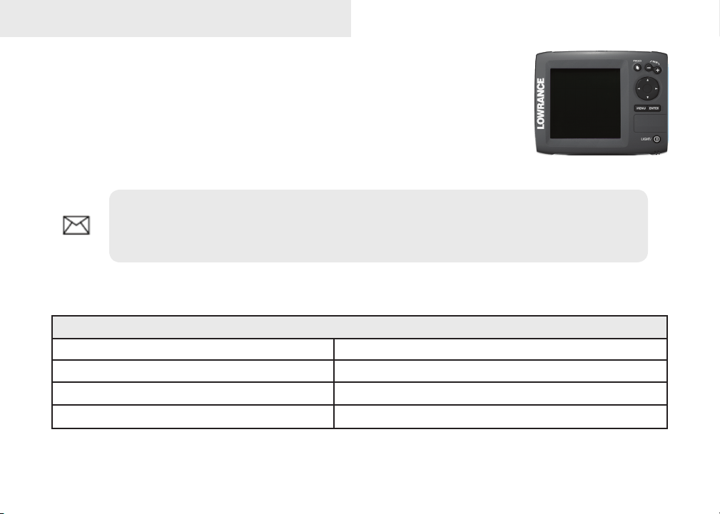
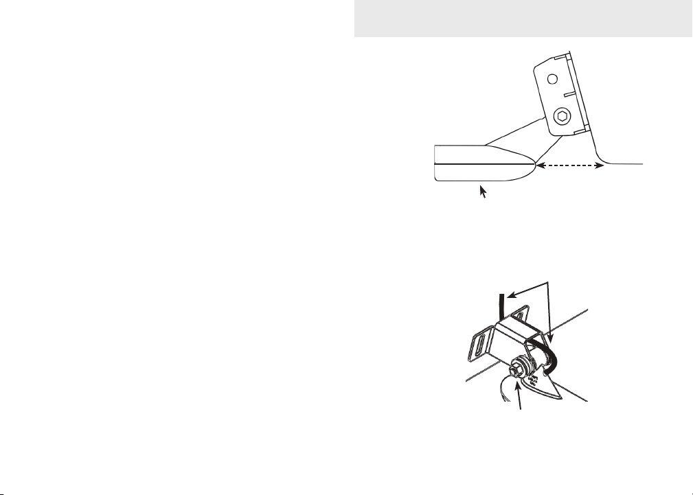
A. Select a transducer location
To function properly the Skimmer transducer must be in the
water at all times and in a location that has a smooth ow of
water when the boat is moving.
If the transducer is not placed in a smooth ow of water,
interference caused by bubbles and turbulence may show
on-screen as random lines or dots. The unit also could lose
bottom signal when the boat is on plane.
NOTE: Mount the transducer at least one foot away from the engine lower unit.
B. Aligning Ratchets on Transducer bracket
You will use the ratchets to ensure the
transducer is installed parallel to the
ground.
Insert the ratchets in the 1.
bracket with the letter “A”
aligned with the dot stamped
on the outside of the
transducer bracket.
Ratchet
3
Bracket
Good locations
Poor locations
Align dot and
letter "A".
dot
A
Installation
Slide the transducer into the bracket and temporarily slide 2.
the bolt through the transducer bracket.
Hold the transducer assembly against the transom. Look at 3.
the transducer from the side. If it is parallel to the ground,
then the “A” position is correct.
If the transducer can not be adjusted so its face is parallel 4.
to the ground, remove the transducer and ratchets from
the bracket. Reinsert the ratchets into the bracket, this time
with the letter “B” aligned with the dot stamped in the bracket. Reassemble the transducer
and bracket and place it against the transom.
Check to see if the transducer will adjust so its face is parallel with the ground. Repeat this 5.
process until the transducer can be adjusted so its face is parallel with the ground.
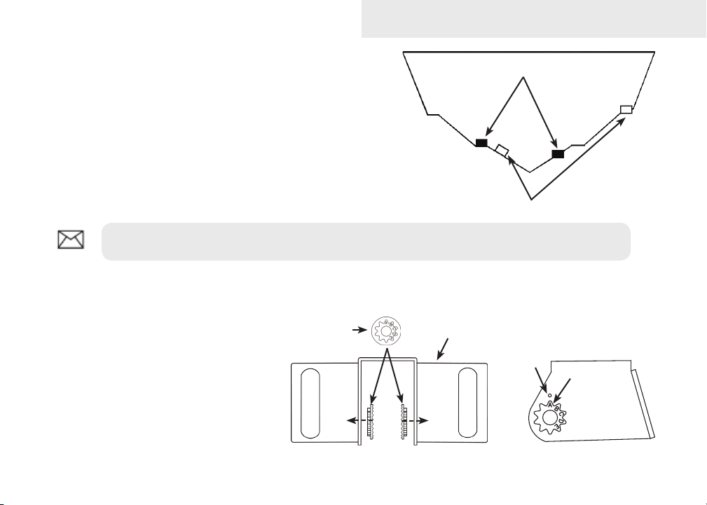
C. Assembling the Transducer bracket
After determining the correct position for the ratchets,
loosely assemble the transducer and bracket assembly.
Lock nut
Rubber washers
Ratchets
Metal washer
Metal washer
Bolt
4
Installation
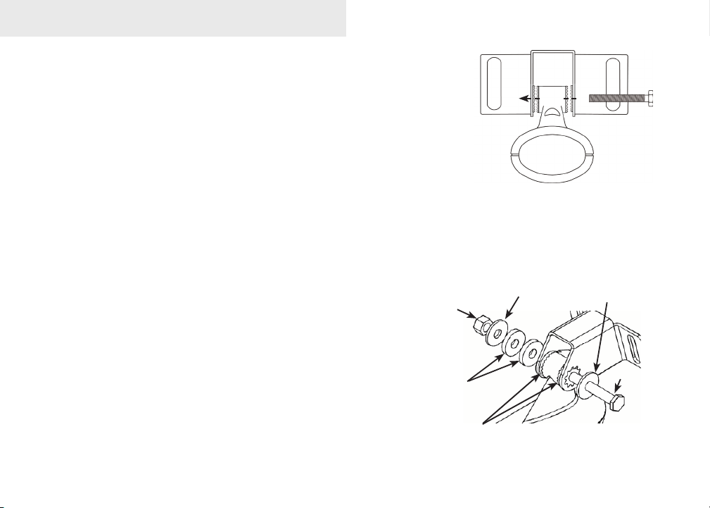
D. Attaching the Transducer to the Transom
Adjust the transducer so its face is parallel with the 1.
ground and its center line is even with the bottom of
the boat hull.
Hold the transducer and bracket assembly against 2.
the transom. When the transducer and bracket are
properly aligned mark its position on the hull.
Drill the mounting holes for the transducer bracket. 3.
Use a #29 bit (for the #10 screws).
Routing cables
When mounting your transducer, make sure to leave some slack
in the cable near the transducer. If you need to drill a hole in the
transom to pass the connector through, the hole size will depend
on the connector on the end of the transducer’s cable.
E. Make a test run to determine the results
After the transducer is installed make a test run to ensure the
transducer is installed properly. Use the slots in the transducer
mounting bracket to loosen the screws and slide the transducer up
or down, if adjustments are necessary.
5
Transom
Bottom of
Transducer face must be
parallel with the ground
Run the cable over
the bolt and through
the bracket.
Do not over tighten the lock nut;
otherwise transducer may not kick-
up if it strikes an object.
hull.
Installation
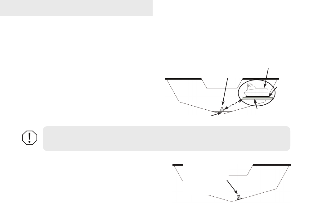
Shoot-thru-hull Skimmer and Pod transducer installation
Before attempting any installation on boats with otation material sandwiched within the hull, consult the
boat manufacturer. In a shoot-thru-hull installation the transducer is epoxied to the inside of the boat hull.
A transducer can not shoot through wood or metal hulls. Wood and metal hulls require either a transom mount
or thru-hull installation. For shoot-thru-hull applications
many boat hulls have a at keel pad that offers a good
transducer mounting surface.
Make sure the Skimmer transducer is oriented so the
nose of the transducer is facing the bow (front) of the
boat. If the transducer has a built in temp sensor, it
will only show the temperature of the hull, not the water
temp.
WARNING: Do not remove material from the inner hull. Careless grinding on the hull could
damage hull integrity. Contact the boat dealer or manufacturer to conrm hull specications
Transducer epoxied to hull
Keel pad
Transducer
Hull
Epoxy
.
Before you epoxy the transducer to the hull, make sure the
area is clean, dry and free of oil or grease.
The surface of the hull must be at so the entire transducer
face is in contact with the hull. Also, make sure the cable is
long enough to reach the sonar unit.
6
On vee hulls
try to place the
transducer where
the dead rise is
10° or less.

To use shoot-thru-hull installation:
Sand the inside surface of the hull, where the transducer is to be epoxied, and the face of 1.
the transducer. Sand the hull until it is smooth to the touch. The sanded area should be
about 1-1/2 times the diameter of the transducer.
2. After sanding, clean the hull and the face of the transducer
with an alcohol wipe to remove any dust.
Apply a thin layer of epoxy (about 1-16” or 1.5 mm) on the 3.
face of the transducer and the sanded area on the hull. Be
careful when mounting a transducer inside a boat hull.
Once epoxied into position, the transducer can be very
difcult to remove.
Press the transducer into the epoxy, turning it to force out any 4.
air bubbles from under the transducer face. Make sure there
are no air pockets in the epoxy layers.
Installation
Sand transducer face
and mounting location
Apply epoxy to transducer
face and mounting location.
Stop pressing when it bottoms out on the hull. Apply pressure 5.
to hold the transducer in place while the epoxy sets. Be careful
not to move the transducer while the epoxy is setting. Allow
the epoxy to set before moving the boat.
When nished, the face of the transducer should be parallel 6.
with the hull with a minimum amount of epoxy between the
hull and transducer.
7
HullEpoxy
Epoxy transducer to hull.
Installation
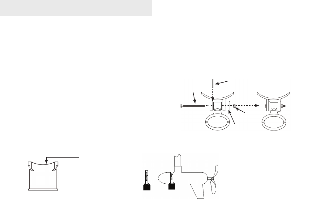
Trolling motor Skimmer and Pod Installation
The TMB-S trolling motor bracket (Part No. 51-45) is an optional accessory and is available through LEI
Extras at www.lei-extras.com. The TMB-S bracket is used to attach a one-piece bracket skimmer transducer
to a trolling motor. The Pod transducer does not need a TMB-S trolling motor bracket to be installed on a
trolling motor. It only needs a hose clamp (adjustable strap).
Installing transducer on trolling motor:
Using the components supplied with the TMB-S 1.
bracket attach the skimmer transducer to the
bracket as shown in the diagram.
Slide the adjustable strap (hose clamp) through 2.
the plastic bracket on the skimmer transducer or
through the Pod transducer slots and then slip
the strap around the trolling motor.
Position the transducer so its face is pointing straight down when the trolling motor is in 3.
the water.
The top of the Pod
transducer is curved to t
the contour of the trolling
motor, so you do not
need a TMB-S mounting
bracket.
Bolt
Internal tooth
washer
Plastic bracket
Lock
nut
Flat washer
Position the transducer
to so its face is pointing
straight down when the
trolling motor is in the
water.
8
Installation
Tighten the adjustable strap 4.
securely to the trolling motor.
Make sure there is enough slack
in the transducer cable for the
trolling motor to turn freely.
Adjustable strap
Plastic ties (not
included)
Transducer
cable
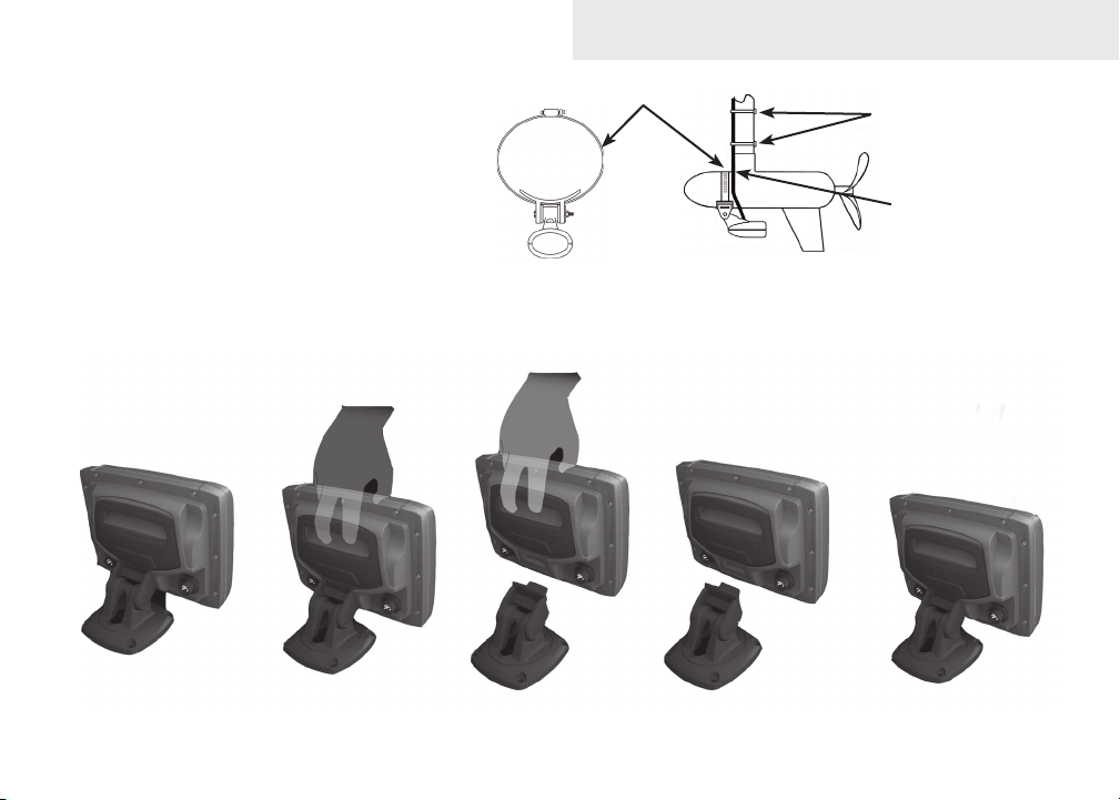
Mounting display unit
Before mounting the display unit mount, make sure there is nothing in the area that will obstruct the display
unit when it is installed on the bracket.
9

Installation
To install bracket mount:
Place the bracket on the desired mounting surface and mark the four mounting holes. If 1.
you want to run the unit’s cables up through the mounting surface, make a mark in the
center of the bracket mounting surface.
Drill pilot holes for the four mounting holes. If desired, use a 1-inch (25mm) bit to drill the 2.
center cabling hole in the mounting surface.
If you are running the cables up through the mounting surface, push the cables through the 3.
mounting surface and then pull them through the cabling hole in the center of the bracket.
Align the mounting bracket with the four mounting holes and use the supplied screws to 4.
fasten it to the mounting surface.
Connect the display unit to the bracket mount. 5.
Connecting to Power
Connect the black wire to a ground. 1.
Attach a 3 Amp fuse to the end of the power wire and then connect the fuse to the positive 2.
(+) terminal on the battery.
Connect the Power cable to the Power port on the back of the display unit. 3.
NOTE: Use 18 gauge wire to extend the power or ground wires.
10
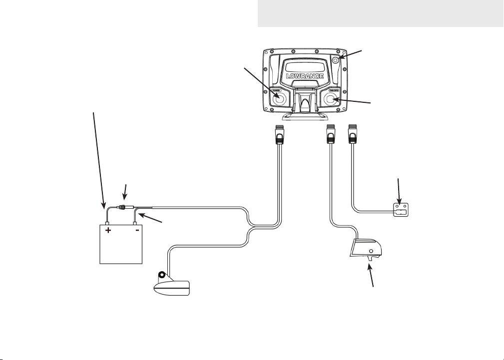
Power
port
Installation
External GPS port
Red (power)
wire
3 Amp
fuse
12V
Speed/temp port;
also used for NMEA
0183
Optional temp
sensor
Black (ground)
wire
Optional paddlewheel
speed/temp sensor
11
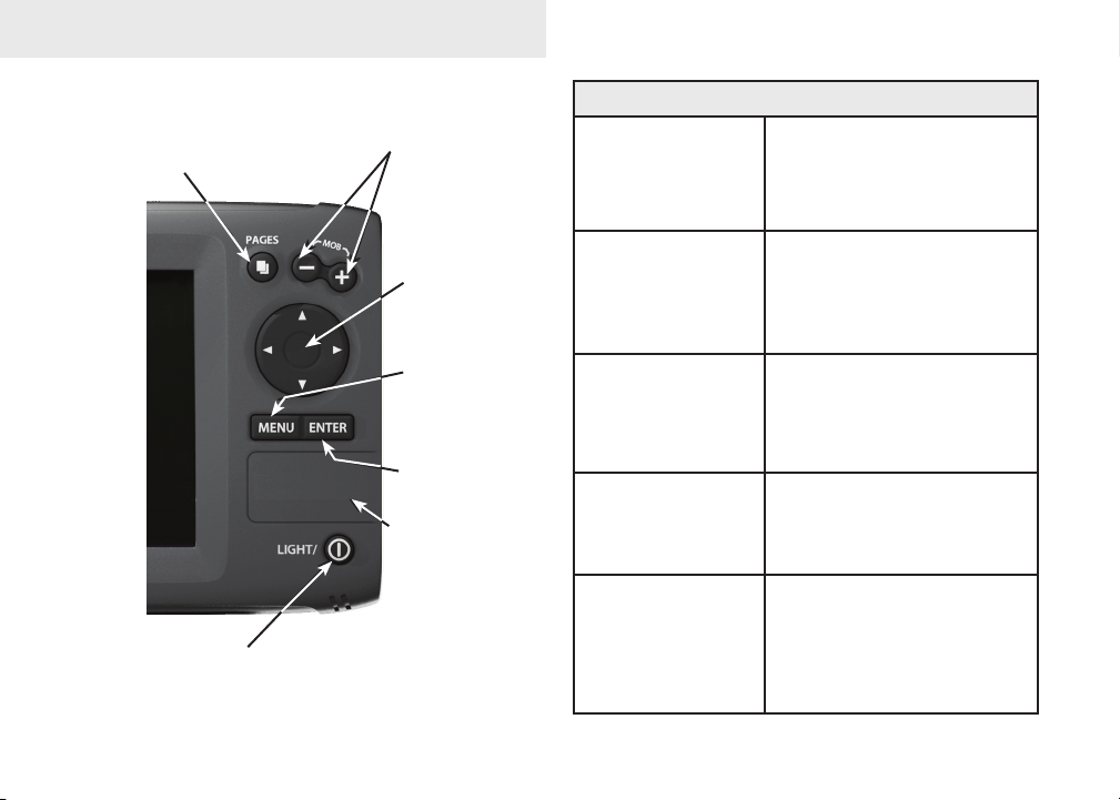
Basic Operation
PAGES: Opens
pages menu;
allows you to
select a page to
view
LIGHT/POWER: controls
backlight level and turns
unit on/off
ZOOM Keys: used to zoom in/zoom
out; press and hold both keys to
create Man Overboard waypoint
KEYPAD:
controls cursor &
selects items on
menus
MENU: Opens
settings, context
and page menus
ENTER: nalizes
menu selections;
save waypoint at
cursor position
microSD CARD
SLOT: insert
microSD card here
Getting Started
Turn unit on/off
Man Overboard
waypoint
Adjusting
the backlight
Muting Audio
Selecting a
GPS Source
To turn on/off the unit,
press and hold the LIGHT/
POWER key for three
seconds.
Press the zoom in and zoom
out keys at the same time
to set a Man Overboard
waypoint at your location.
This unit has
11 backlight
levels. Press the LIGHT/
POWER key to switch
backlight levels.
Select Mute Audio from the
System menu and press
ENTER.
Select
GPS Source from the
System menu and press
ENTER. Select internal
or
external and press
ENTER.
12
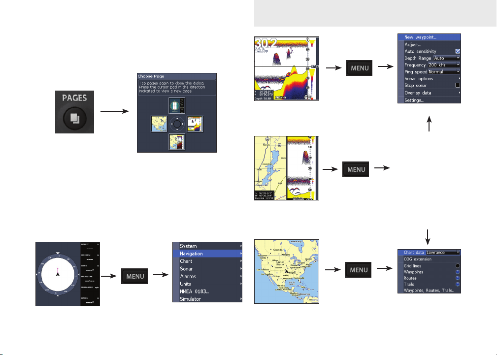
Menu operation
This unit has four page screens: Steer, Sonar, Chart/
Sonar and Chart.
Basic Operation
Pages menu
Page context menus
The Sonar, Chart/Sonar and Chart pages have menus
that can only be accessed when those pages are
displayed.
Steer page
Settings menu
Sonar Page
(Elite 5 only)
Chart/Sonar page
(Elite 5 only)
Chart page
13
Sonar menu
Chart or sonar
menu will appear
depending on
which panel is
active. Press
the
PAGES key
twice to switch
active panels.
Chart menu
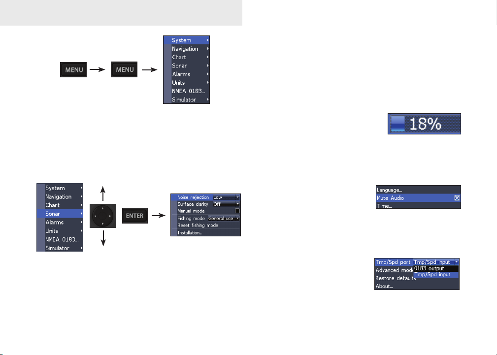
Basic Operation
Making adjustments
There are several menu types used to make
adjustments to options and settings, including
scrollbars, on/off features and dropdown menus.
Settings menu
Accessing menu items
The keypad and ENTER key are used to select
menu items and open submenus. Use the keypad to
highlight the desired item and press ENTER.
Scrollbars
Select the scrollbar and press
the keypad left (decrease) or
right (increase).
On/Off features
Select an on/off menu item
and press ENTER to turn it
on/off.
Dropdown menus
Press the keypad up/down
to select the desired item
and press ENTER.
14
 Loading...