

Page 1
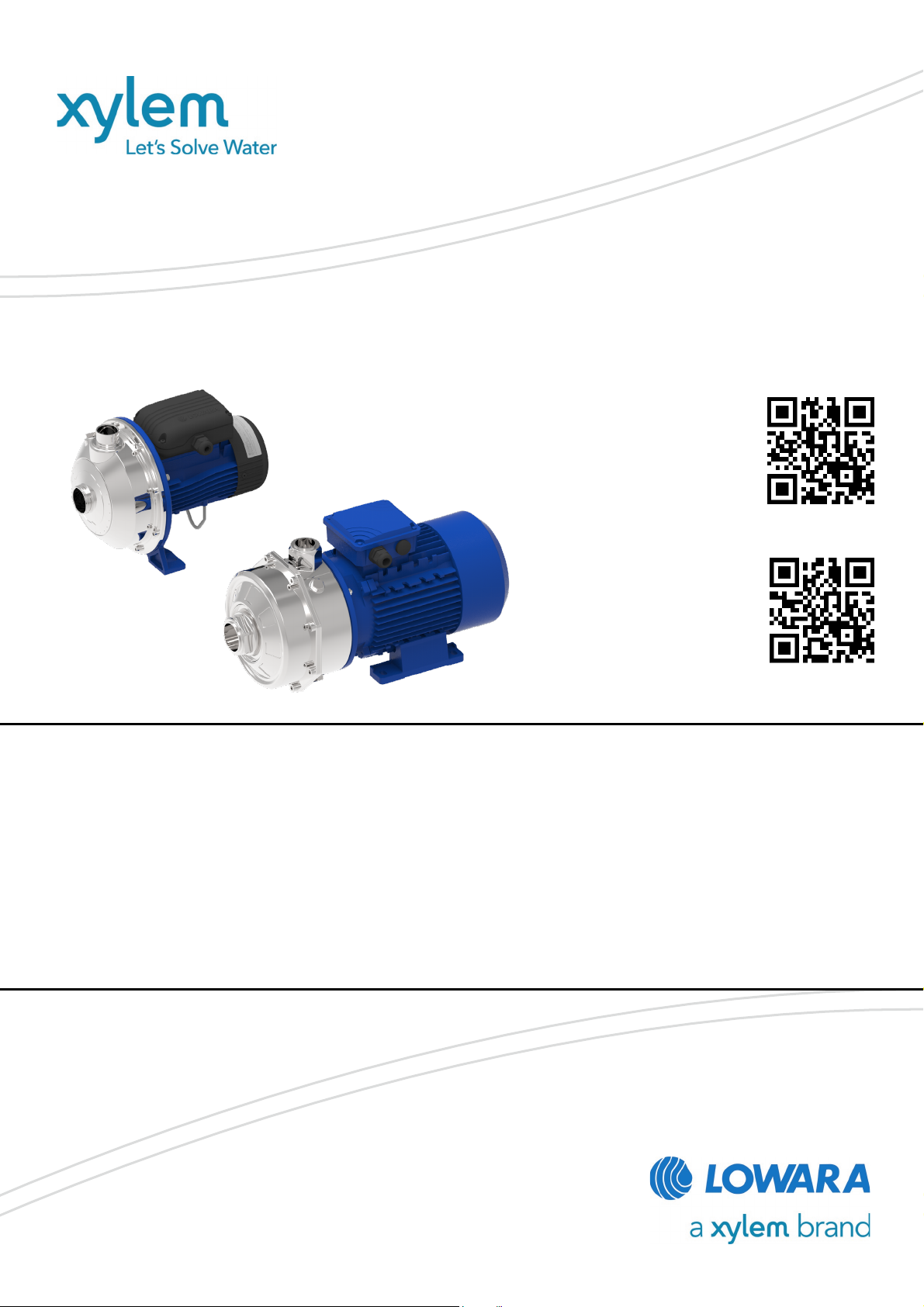
CEA-CIE, CA series
Additional Installation, Operation and
CA
0
Maintenance Instructions
CEA
Single and twin impeller close-coupled
centrifugal electric pumps
Page 2

en - Original Instructions
Table of Contents
1 Introduction and Safety ............................................................................................................................................ 4
1.1 Introduction ...................................................................................................................................................... 4
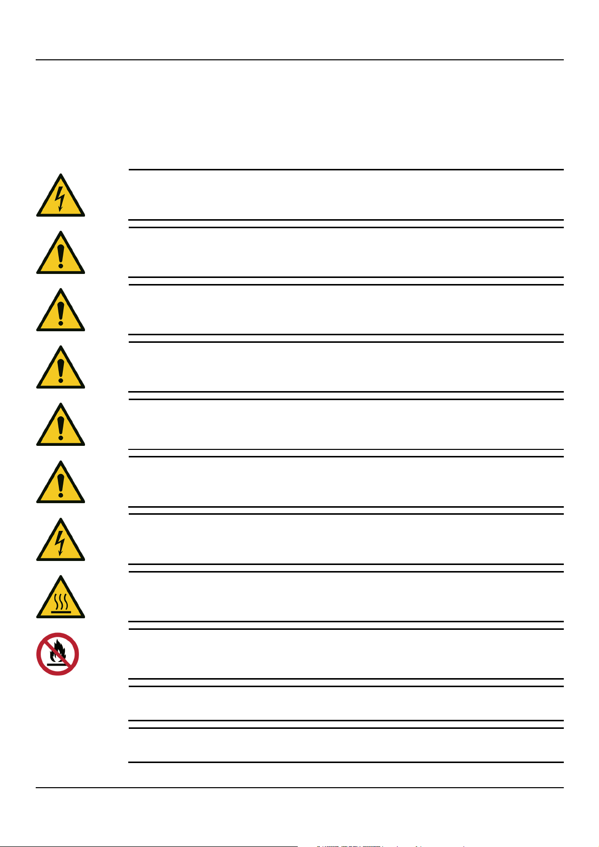
1.2 Hazard levels and safety symbols .................................................................................................................... 4
1.3 User safety ........................................................................................................................................................ 6
1.4 Protection of the environment ......................................................................................................................... 6
2 Handling and storage ............................................................................................................................................... 7
2.1 Precautions ....................................................................................................................................................... 7
2.2 Unit inspection upon delivery .......................................................................................................................... 8
2.2.1 Package inspection .................................................................................................................................. 8
2.2.2 Unpacking and inspection of the unit ..................................................................................................... 8
2.3 Lifting and positioning the unit........................................................................................................................ 8
2.4 Storage ............................................................................................................................................................. 9
3 Product Description ................................................................................................................................................ 11
3.1 Features .......................................................................................................................................................... 11
3.1.1 Use in water distribution networks for human consumption ............................................................... 12
3.2 Part names ...................................................................................................................................................... 13
3.3 Data plate ....................................................................................................................................................... 15
3.4 Identification code ......................................................................................................................................... 16
3.5 Liquid temperature plate ............................................................................................................................... 16
4 Mechanical installation ........................................................................................................................................... 18
4.1 Precautions ..................................................................................................................................................... 18
4.2 Installation area .............................................................................................................................................. 19
4.3 Requirements on the concrete foundation ................................................................................................... 20
4.4 Permitted positions ........................................................................................................................................ 20
4.5 Fastening ........................................................................................................................................................ 20
4.6 Reducing vibrations ....................................................................................................................................... 20
4.7 Environments prone to condensation ........................................................................................................... 21
5 Hydraulic connection .............................................................................................................................................. 22
5.1 Preliminary operations ................................................................................................................................... 22
5.2 Guidelines for the suction side ...................................................................................................................... 22
5.2.1 Positive suction head installation .......................................................................................................... 23
5.2.2 Suction lift installation ............................................................................................................................ 24
5.3 Guidelines for the discharge side .................................................................................................................. 25
6 Electrical connection ............................................................................................................................................... 26
6.1 Guidelines for electrical connection .............................................................................................................. 26
6.2 Guidelines for the control panel .................................................................................................................... 26
6.3 Motor connection ........................................................................................................................................... 26
6.4 Operation with frequency converter ............................................................................................................. 27
7 Use and operation .................................................................................................................................................. 28
2 CEA, CIE, CA series – Additional Installation, Operation and Maintenance Instructions
Page 3

en - Original Instructions
7.1 Precautions ..................................................................................................................................................... 28
7.2 Filling and priming ......................................................................................................................................... 29
7.3 Checking the direction of rotation (three-phase motor) .............................................................................. 30
7.3.1 Wrong rotation direction (three-phase motor) ..................................................................................... 30
7.4 Startup ............................................................................................................................................................ 30
7.5 Stopping the unit ............................................................................................................................................ 32
8 Maintenance ............................................................................................................................................................ 33
8.1 Precautions ..................................................................................................................................................... 33
8.2 Maintenance every 4000 hours of operation, or every year ........................................................................ 33
8.3 Maintenance every 10000 hours of operation or every 2 years .................................................................. 33
8.4 Maintenance every 17500 hours of operation or every 5 years .................................................................. 33
8.5 Long periods of inactivity ............................................................................................................................... 34
8.6 Identification of spare parts ........................................................................................................................... 34
9 Troubleshooting...................................................................................................................................................... 35
9.1 The unit does not switch on ........................................................................................................................... 35
9.2 Little or no hydraulic performance ................................................................................................................ 35
9.3 The unit starts and stops too frequently ........................................................................................................ 36
9.4 The unit produces excessive noise and/or vibrations .................................................................................. 36
9.5 The unit is leaking at the mechanical seal ..................................................................................................... 37
9.6 The motor becomes excessively hot ............................................................................................................. 37
9.7 Tripping of the thermal motor protection ..................................................................................................... 37
9.8 The residual current protection device (RCD) has tripped .......................................................................... 37
10 Specifications .......................................................................................................................................................... 38
10.1 Operating environment ................................................................................................................................. 38
10.2 Operating temperature and pressure ........................................................................................................... 38
10.3 Maximum head ............................................................................................................................................... 39
10.3.1 CEA and CIE series ................................................................................................................................. 39
10.3.2 CA series ................................................................................................................................................. 39
10.4 Maximum number of starts and stops ........................................................................................................... 40
10.5 Electrical specifications .................................................................................................................................. 40
10.6 Sound pressure .............................................................................................................................................. 40
10.7 Materials in contact with the liquid ............................................................................................................... 40
11 Disposal ................................................................................................................................................................... 41
11.1 Precautions ..................................................................................................................................................... 41
11.2 WEEE (EU/EEA) .............................................................................................................................................. 41
11.3 WEEE (UK) ...................................................................................................................................................... 42
12 Declarations ............................................................................................................................................................ 43
12.1 Electric pump ................................................................................................................................................. 43
12.2 Pump unit (electric pump) (UKCA) ................................................................................................................ 45
13 Warranty .................................................................................................................................................................. 47
CEA, CIE, CA series – Additional Installation, Operation and Maintenance Instructions 3
Page 4
en - Original Instructions
Hazard level
Indication
DANGER:
It identifies a dangerous situation which, if not avoided, causes
WARNING:
It identifies a dangerous situation which, if not avoided, may cause
CAUTION:
It identifies a dangerous situation which, if not avoided, may cause
NOTE:
It identifies a situation which, if not avoided, may cause damage to
property but not to people.
1 Introduction and Safety
1.1 Introduction
Purpose of this manual
This manual provides information on how to do the following in the correct manner:
• Installation
• Operation
• Maintenance.
Supplementary instructions
The instructions and warnings of this manual apply to the standard electric pump (hereinafter
unit) as described in the sale documentation. Special version pumps may be supplied with
supplementary instruction manuals. For situations not considered in the manual or in the
commercial documentation, contact Xylem or the Authorised Distributor.
1.2 Hazard levels and safety symbols
Before using the unit, the user must read, understand and comply with the indications of the
danger warnings in order to avoid the following risks:
• Injuries and health hazards
• Damage to the product
• Unit malfunction.
Hazard levels
serious injury, or even death.
serious injury, or even death.
small or medium level injuries.
4 CEA, CIE, CA series – Additional Installation, Operation and Maintenance Instructions
Page 5
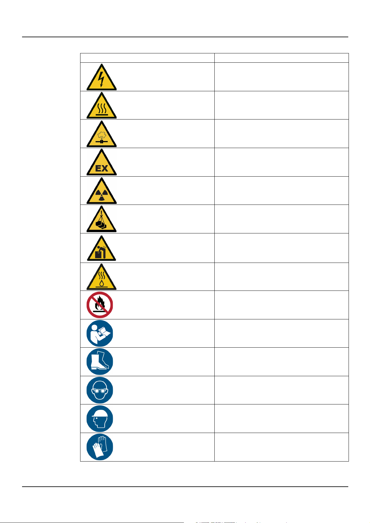
Complementary symbols
Symbol
Description
Electrical hazard
Hot surface hazard
Danger, pressurized system
Explosive atmosphere hazard
Ionizing radiation hazard
Danger, suspended loads
Danger from heavy manual loads
Hot liquid danger
Do not use flammable liquids
Obligation to read the instruction manual
Obligation to wear safety shoes
Obligation to wear safety glasses
Obligation to wear a safety helmet
Obligation to wear safety gloves
en - Original Instructions
CEA, CIE, CA series – Additional Installation, Operation and Maintenance Instructions 5
Page 6
en - Original Instructions
WARNING:
The installation, operation,
qualified personnel only. Qualified personnel are persons who are able to recognise risks and
avoid dangers during these operations.
WARNING:
• For EU countries: this product may be used by children aged 8 years and above and persons
knowledge, provided that they are being supervised and have been instructed on how to use
• For countries outside the EU: this product is not intended for use by persons (including
play with the product.
WARNING:
Always wear personal protective equipment.
WARNING: Ionizing radiation hazard
If the unit has been exposed to
for the protection of people. If the unit needs to be dispatched, inform the carrier and the
recipient accordingly, so that appropriate safety measures can be put in place.
WARNING:
It is prohibited to dispose of lubricating fluids and other hazardous substances in the
environment.
1.3 User safety
Strictly comply with current health and safety regulations.
Qualified personnel
Inexperienced users
maintenance and troubleshooting of the unit are reserved for
Personal protective equipment
Sites exposed to ionizing radiations
with reduced physical, sensory or mental capabilities, or who lack experience and
it safely, and understand the hazards involved. Children must not play with the product.
Cleaning and maintenance must not be carried out by children without supervision.
children) with reduced physical, sensory or mental capabilities, or who lack experience and
knowledge, unless they are being supervised and have been instructed on how to use it by a
person responsible for their safety. Children should be supervised to ensure that they do not
ionizing radiations, implement the necessary safety measures
1.4 Protection of the environment
Disposal of packaging and product
Comply with the current regulations on sorted waste disposal, see Disposal.
Leaking of fluid
If the unit contains lubricating fluid, take appropriate measures to prevent the dispersion of
leaks into the environment.
6 CEA, CIE, CA series – Additional Installation, Operation and Maintenance Instructions
Page 7
2 Handling and storage
DANGER: Electrical hazard
Before starting work, check that the electric power supply is disconnected and locked out, to
avoid unintentional restart of the unit, the control panel and the auxiliary control circuit.
WARNING: Crushing hazard
The unit and components are heavy: risk of crushing.
WARNING: Danger from heavy manual loads
Check the gross weight on the packaging before handling the unit.
WARNING: Danger from heavy manual loads
Check the net
WARNING: Danger from heavy manual loads
Handle the unit in compliance with the current regulations on "manual load handling", to avoid
undesirable ergonomic conditions causing risks of back
WARNING:
Take appropriate measures during transport, installation and storage to prevent contamination
from external substances.
WARNING:
Use ropes, cords, hooks and/or carabiners (hereinafter referred to as “hooks”) that comply with
current directives and are suitable for the specific task.
WARNING:
Lift and handle the unit slowly to avoid stability issues.
WARNING:
During handling, make sure to avoid injury to people and animals, and/or damage to property.
NOTE:
Make sure that the harnessing does not hit and/or damage the unit.
2.1 Precautions
Before starting any work, make sure to read and understand all the safety instructions in
Introduction and Safety.
Handling and positioning the unit
en - Original Instructions
weight on the nameplate before handling the unit.
-spine injury.
CEA, CIE, CA series – Additional Installation, Operation and Maintenance Instructions 7
Page 8
en - Original Instructions
2.2 Unit inspection upon delivery
2.2.1 Package inspection
1. Check that quantity, descriptions and product codes match the order.
2. Check the packaging for any damage or missing components.
3. In case of immediately detectable damage or missing parts:
• Accept the goods with reserve, indicating any findings on the transport document, or
• Reject the goods, indicating the reason on the transport document.
In both cases, promptly contact Xylem or the Authorised Distributor from whom the
product was purchased.
2.2.2 Unpacking and inspection of the unit
1. Remove the packaging.
2. Ensure sorting of all packaging materials in accordance with the applicable regulations.
3. Free the unit by removing any straps.
4. Check the unit for integrity and to make sure that there are no missing components.
5. In case of damage or missing components, promptly contact Xylem or the Authorised
Distributor.
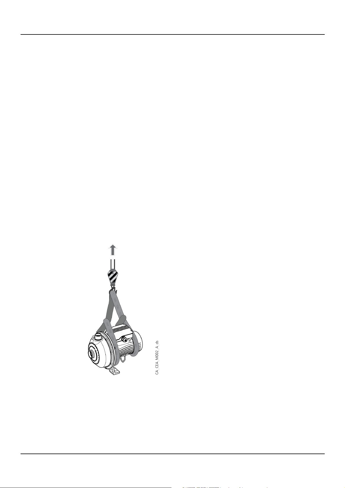
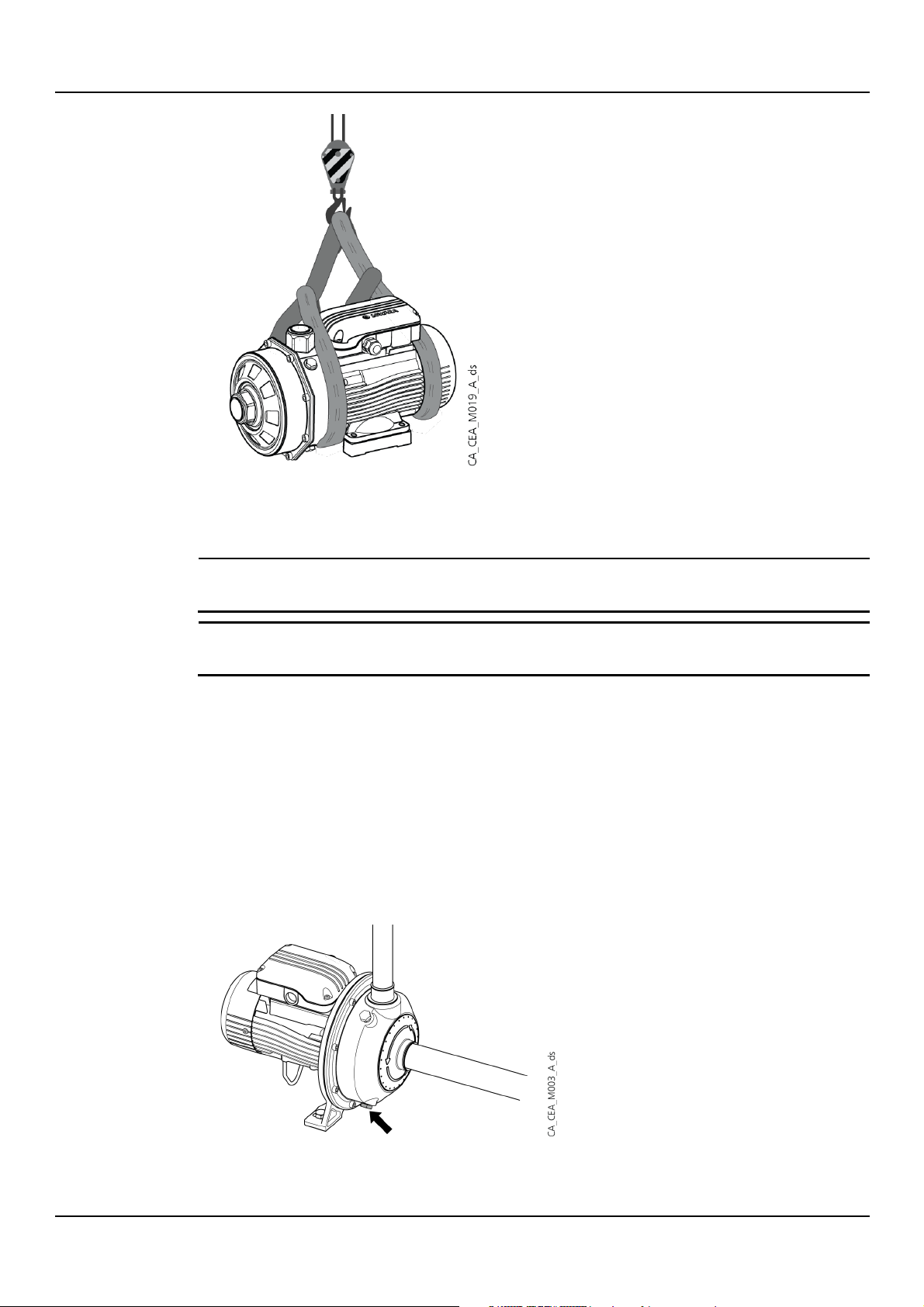
2.3 Lifting and positioning the unit
1. Make two tie-down slings around the unit with two ropes.
2. Fix the two ropes to the crane.
3. Slowly lift and move the unit.
4. Set the unit down slowly.
5. Release the harness.
The figure shows how to harness and lift the unit for CEA and CIE models.
8 CEA, CIE, CA series – Additional Installation, Operation and Maintenance Instructions
The figure shows how to harness and lift the unit for CA models.
Page 9
2.4 Storage
NOTE:
Do not place heavy loads on top of the unit.
NOTE:
Protect the unit from collisions.
en - Original Instructions
Storage of the packed unit
The unit must be stored:
• In a covered and dry place
• Away from heat sources
• Protected from dirt
• Protected from vibrations
• At an ambient temperature between -5°C and +40°C (23°F and 140°F), and relative
humidity between 5% and 95%.
Long-term storage of the installed unit
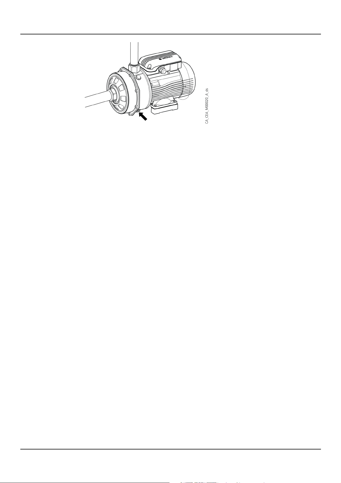
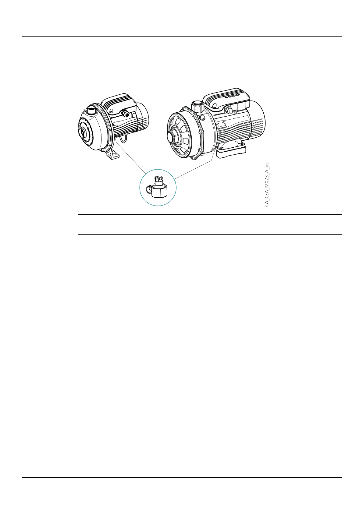
1. Empty the unit by removing the drain plug.
The figure shows the position of the drain plug for CEA models.
The figure shows the position of the drain plug for CA models.
CEA, CIE, CA series – Additional Installation, Operation and Maintenance Instructions 9
Page 10
en - Original Instructions
2. For storage periods longer than 5 years, check:
3. When starting the unit for the first time after an extended storage period, check for any
For more information on long-term storage contact the Xylem sales company or Authorised
Distributor.
This operation is essential in environments with cold temperatures. Otherwise, any residual
liquid in the unit could have an adverse effect on its condition and performance.
• The electrical condition of the capacitor (if present)
• The integrity of the elastomers inside the unit. Replace them if damaged or worn
leakage due to wear of the elastomers caused by inactivity.
10 CEA, CIE, CA series – Additional Installation, Operation and Maintenance Instructions
Page 11
3 Product Description
Series
Name
CEA
Stainless steel single-impeller close-coupled centrifugal electric pump.
CA
Double impeller horizontal close-coupled centrifugal electric pump.
Model
Name
CIE
CEA series electric pump, for use in HVAC applications.
CA..V, CA..N
CA series electric pump, for dedicated use.
CEA..V/CEA..N:
CEA series electric pump, for dedicated use.
DANGER: Potentially explosive atmosphere hazard
It is prohibited to start the unit in environments with potentially explosive
atmospheres or with combustible dusts.
DANGER:
It is prohibited to use this unit to pump
NOTE:
When using liquids with a density and/or viscosity higher than that of water, such as a mixture
of water and glycol, contact Xylem or the Authorised Distributor to check whether a motor with
a higher power rating is required.
3.1 Features
Designation of standard models
Designation of special versions
en - Original Instructions
Intended use
Pumped liquids
• Transfer of clean, non-aggressive water, free of dissolved gases
• Pressure boosting and water supply systems
• Washing and cleaning industry
• Circulation of hot and cold liquids, for example water or water & glycol, for heating, cooling
and air conditioning systems
• Water treatment applications
• Transfer of moderately chemically aggressive liquids
• Irrigation
Observe the operating limits in Specifications.
For other applications, contact Xylem or the Authorised Distributor.
• Cold water
• Hot water
• Clean
• Chemically and mechanically non aggressive.
Contact Xylem or the Authorised Distributor for other liquids.
flammable and/or explosive liquids.
ì
CEA, CIE, CA series – Additional Installation, Operation and Maintenance Instructions 11
Page 12
en - Original Instructions
NOTE:
When using chemically treated water (softened, deionised, demineralised, etc.) and for any
situation other than those described in the liquid type, please contact Xylem or the Authorised
Distributor.
WARNING:
It is prohibited to pump drinking water after use with other fluids.
WARNING:
Take appropriate measures during transport, installation and storage to prevent contamination
from external substances.
WARNING:
Remove the unit from its packaging just before installation to prevent contamination from
external substances.
WARNING:
After installation, run the
inside of the system.
3.1.1 Use in water distribution networks for human consumption
If the unit is intended for water supply to people and/or animals:
unit for a few minutes with several users open in order to wash the
12 CEA, CIE, CA series – Additional Installation, Operation and Maintenance Instructions
Page 13
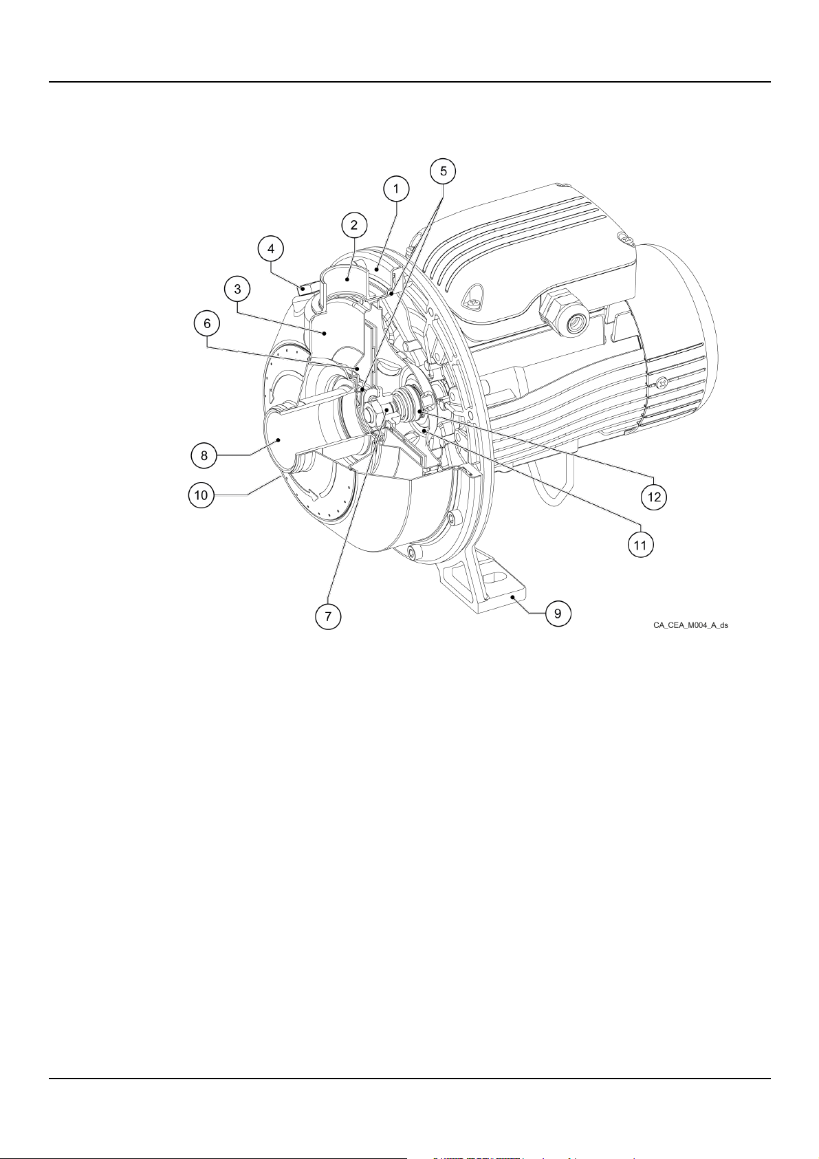
3.2 Part names
CEA series
en - Original Instructions
1. Pump body
2. Discharge port
3. Diffuser
4. Filling plug
5. Elastomers
6. Impeller
7. Shaft
8. Suction port
9. Motor adapter with attachments
10. Drain plug
11. Seal housing
12. Mechanical seal
CEA, CIE, CA series – Additional Installation, Operation and Maintenance Instructions 13
Page 14
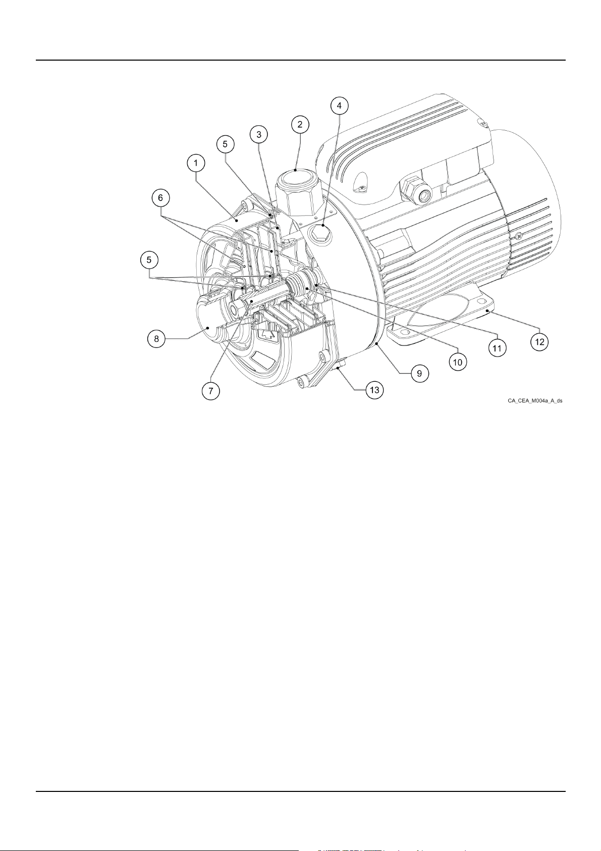
en - Original Instructions
CA series
1. Pump body
2. Discharge port
3. Diffuser
4. Filling plug
5. Elastomers
6. Impeller
7. Shaft
8. Suction port
9. Motor adapter
10. Mechanical seal
11. Seal housing
12. Supporting foot
13. Drain plug
14 CEA, CIE, CA series – Additional Installation, Operation and Maintenance Instructions
Page 15
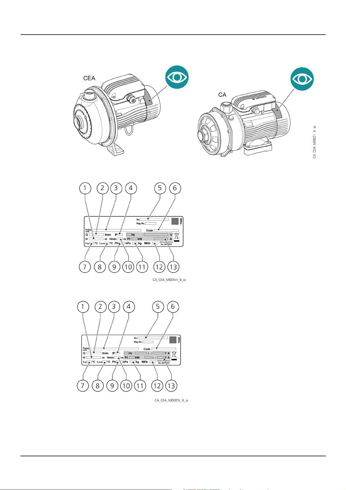
3.3 Data plate
The figure shows the position of the data plate based on model.
The figure shows the data plate with single-phase motor.
en - Original Instructions
The figure shows the data plate with three-phase motor.
1. Head range
2. Flow rate range
3. Identification code
4. Protection degree of the unit
5. Serial number (date+progressive number)
6. Product code
7. Maximum operating temperature of the liquid (for usage in compliance with EN 60335-2-41)
8. Maximum temperature of the ambient of use
CEA, CIE, CA series – Additional Installation, Operation and Maintenance Instructions 15
Page 16
en - Original Instructions
9. Maximum operating pressure
10. Minimum head (EN 60335-2-41)
11. Weight
12. Minimum efficiency index (MEI)
13. Electrical data
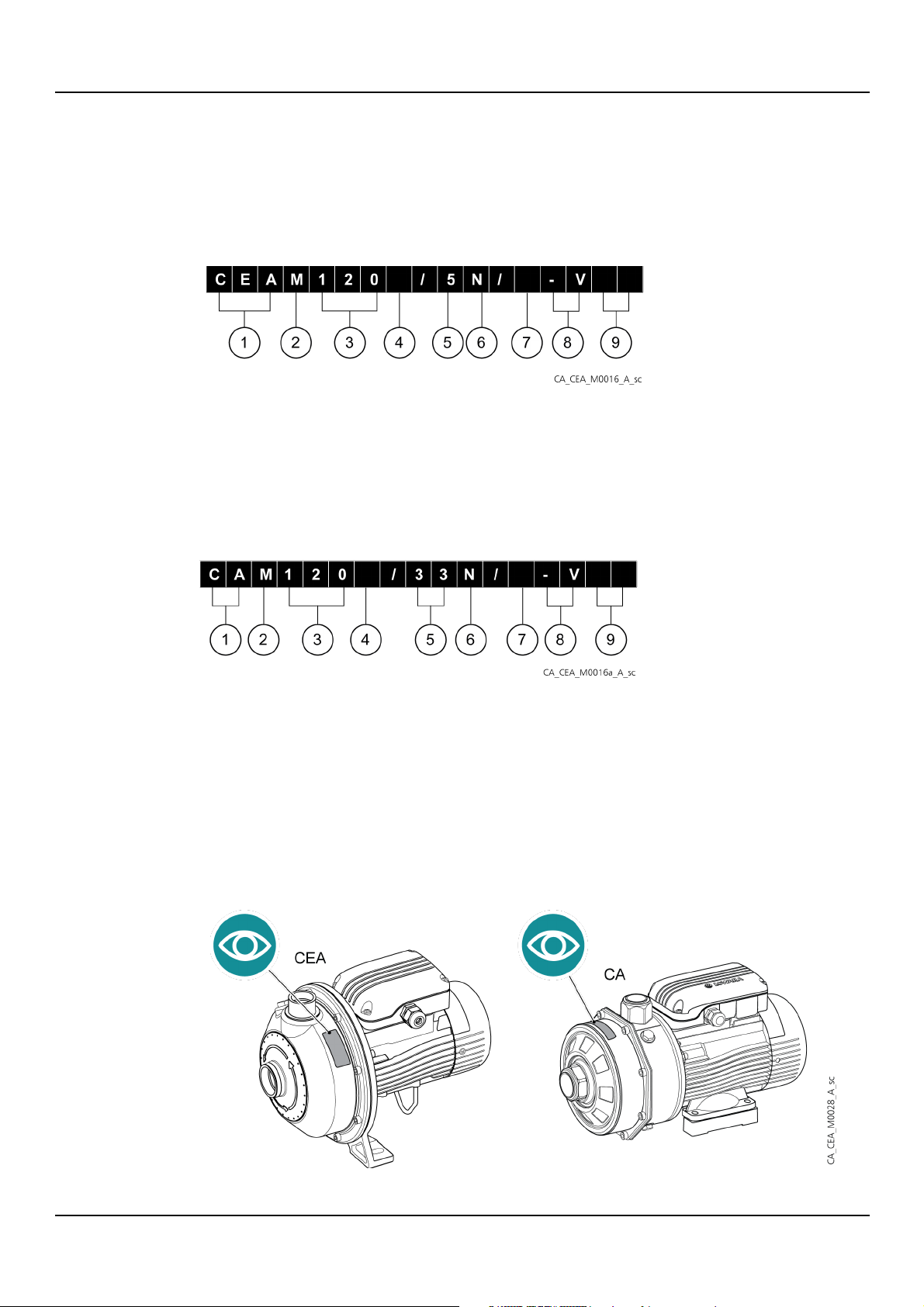
3.4 Identification code
CEA series
1. CEA, CIE series name
2. Phase [_] = three-phase, [M] = single-phase
3. Nominal flow rate in l/min
4. Frequency [6] = 60 Hz, [_] = 50 Hz
5. Impeller size, dimensionless value
6. Material [_] = AISI 304 version, N = AISI 316 (CEA ..N) version, V = Victaulic® connections
7. Motor efficiency level [A] = IE2 three-phase version, [D] = IE3 three-phase version, [C] = IE2 single-phase version
8. Elastomer material [_] = NBR gaskets for CEA, EPDM gaskets for CEA..N and CIE, [V] = FKM gaskets
9. Extra description [_] = standard version, letter assigned by the manufacturer
CA series
1. CA series name
2. Phase [_] = three-phase, [M] = single-phase
3. Nominal flow rate in l/min
4. Frequency [6] = 60 Hz, [_] = 50 Hz
5.
6. Impeller size, dimensionless value
7. Material [_] = AISI 304 (CA) version, N = AISI 316 (CA ..N) version
8. Motor efficiency level [D] = IE3 three-phase version, [C] = IE2 single-phase version
9. Elastomer material [_] = NBR gaskets for CA, EPDM gaskets for CA..N, [V] = FPM gaskets for CA, CA..N
10. Extra description [_] = standard version, letter assigned by the manufacturer
3.5 Liquid temperature plate
The figure shows the position of the liquid temperature data plate based on model.
16 CEA, CIE, CA series – Additional Installation, Operation and Maintenance Instructions
Page 17
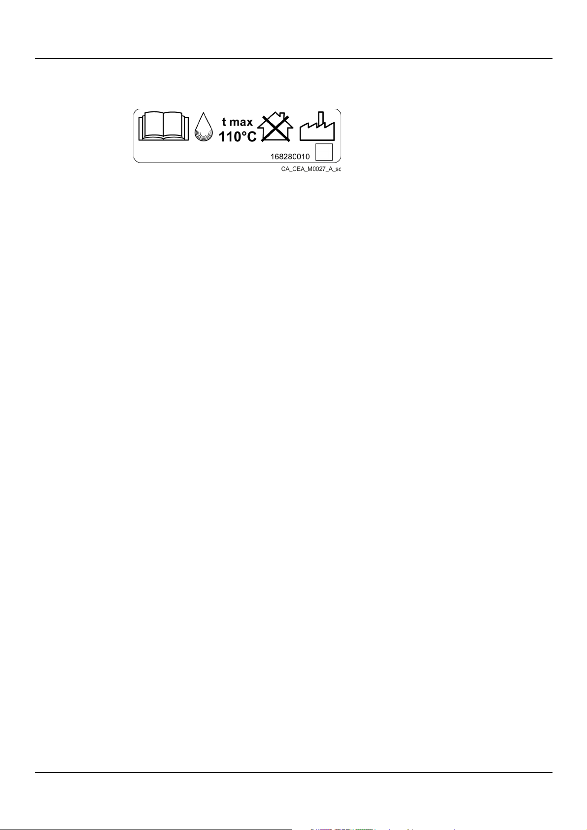
It is applied on the units where the maximum working temperature of the liquid exceeds the
limit of 110°C (230°F), foreseen by the EN 60335-2-41 standard, with Un (V) ≤ 480 V (3~) or ≤
250 V (1~).
en - Original Instructions
CEA, CIE, CA series – Additional Installation, Operation and Maintenance Instructions 17
Page 18
en - Original Instructions
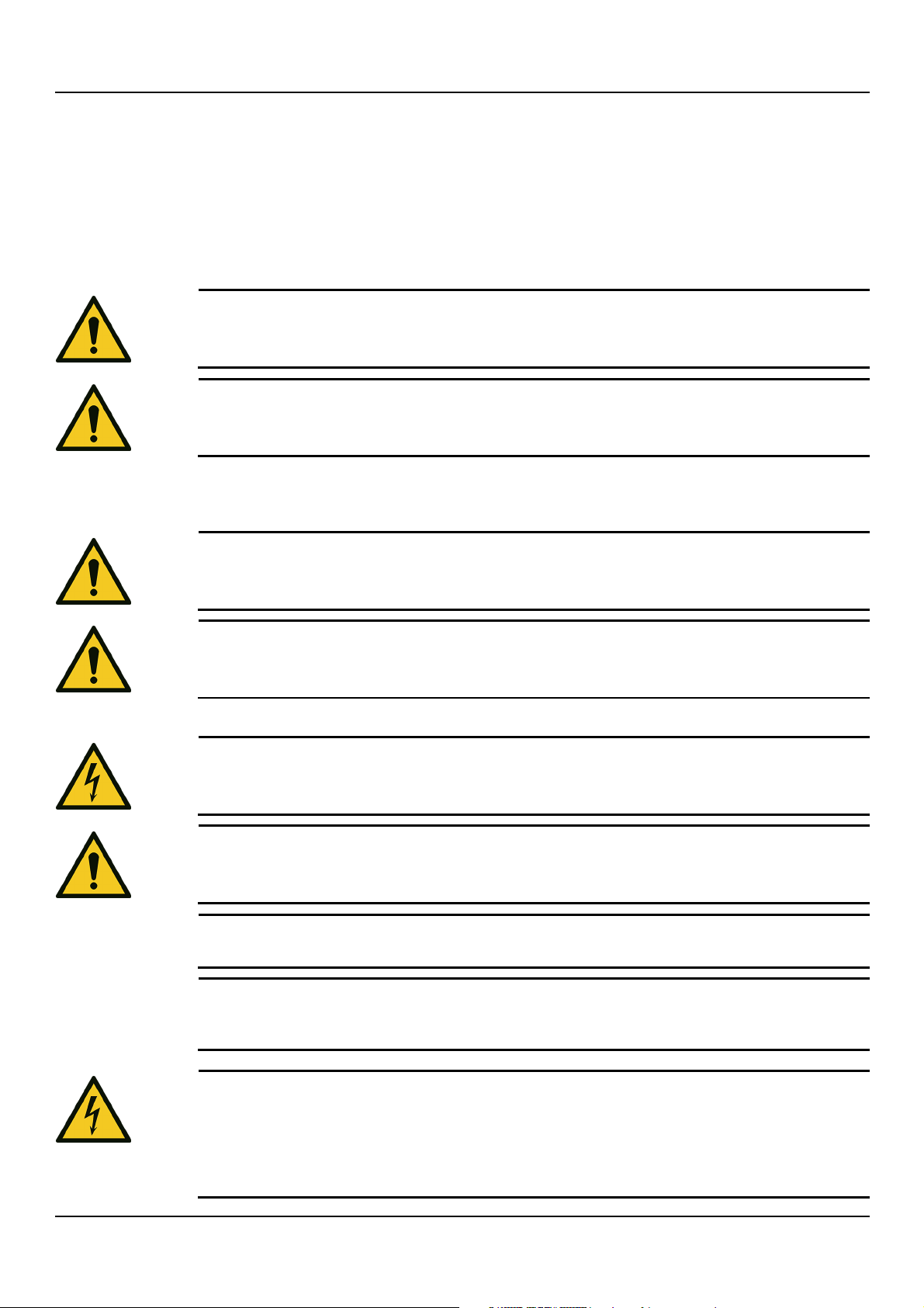
WARNING:
Always use suitable working tools.
WARNING:
When selecting the place of installation and connecting the unit to the hydraulic and electric
power supplies, strictly comply with current regulations.
WARNING:
Piping must be sized to ensure safety at the maximum operating pressure.
WARNING:
Install appropriate
DANGER: Electrical hazard
Before starting work, check that the electric power supply is disconnected and locked out, to
avoid unintentional restart of the unit, the control panel and
WARNING:
The absorbed current must be below the rated limits. Refer to the values on the data plate.
NOTE:
The mains voltage and frequency must match the specifications on the data plate.
NOTE:
Before
firefighting systems (hydrants or sprinklers) comply with local regulations.
DANGER: Electrical hazard
1)
attempting to make any other electrical connections. 2) Connect all the electrical accessories of
the unit to the ground. 3) Check that the external protection conductor (ground) is longer than
the phase conductors. In case of accidental disconnection of the unit from the phase
conductors, the protection conductor must be the last one to detach itself from the terminal. 4)
4 Mechanical installation
4.1 Precautions
General precautions
Before starting any work, make sure to read and understand all the safety instructions in
Introduction and Safety.
When connecting the unit to a public or private aqueduct, or when placing it into a well for the
supply of water for human and/or animal consumption, see Use in water distribution networks
for human consumption.
Electrical measures
gaskets between the unit and the piping system.
the auxiliary control circuit.
starting work, make sure that the general electric requirements and/or those of the
Ground
Always connect the external protection conductor (ground) to the ground terminal before
18 CEA, CIE, CA series – Additional Installation, Operation and Maintenance Instructions
Page 19
Install suitable systems for protection against indirect contact, in order to prevent lethal electric
shocks.
4.2 Installation area
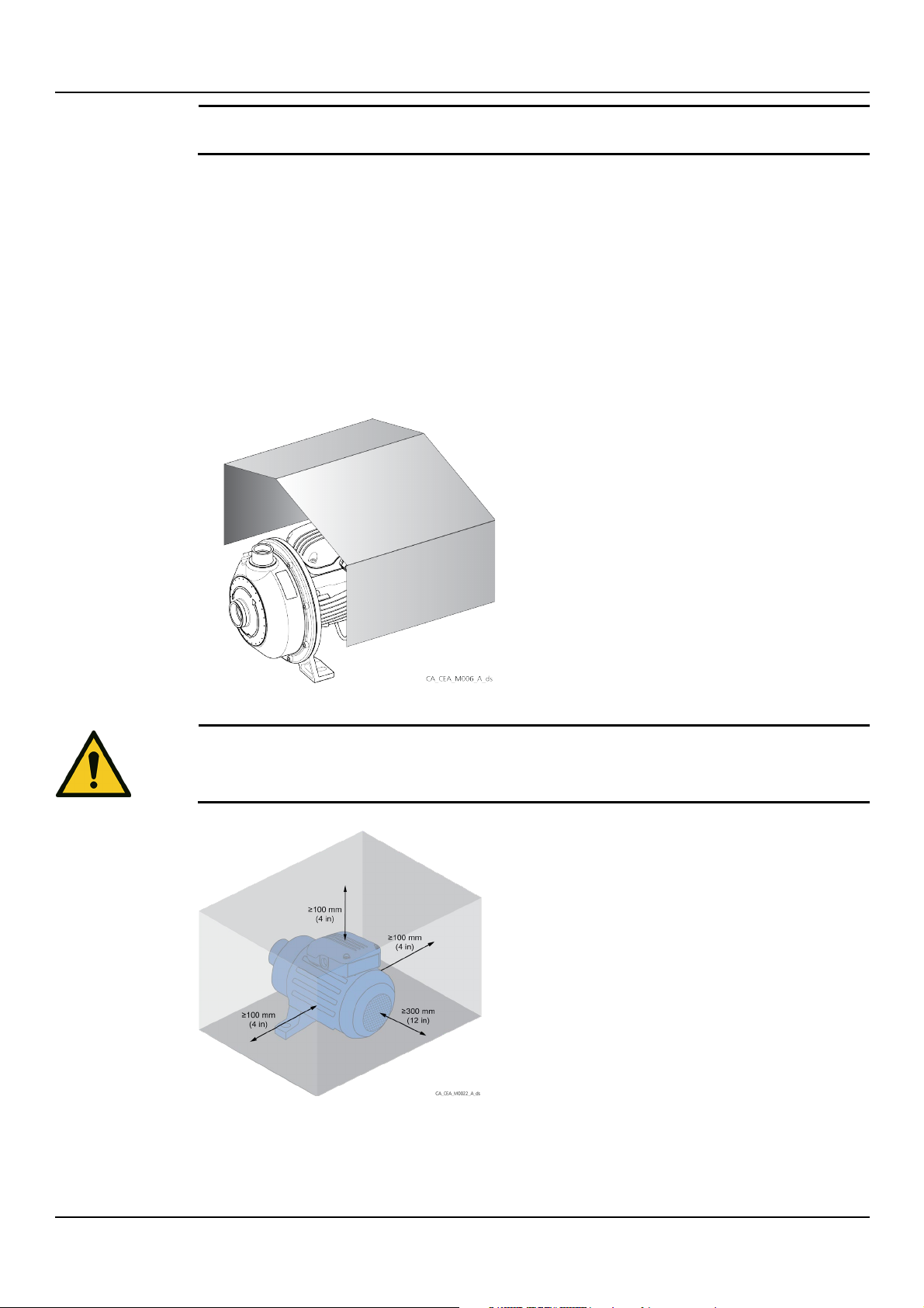
WARNING:
Observe the distances indicated for ventilation of the unit and to allow for any operations on
the motor, see the figure below.
1. Install the unit on a concrete or metal foundation base sufficiently strong to ensure
permanent and rigid support, see Requirements on the concrete foundation.
2. Follow the provisions in Operating environment.
3. Place the unit in a raised position in relation to the floor.
4. Install the unit in an accessible location.
5. Leave sufficient space around the unit to allow for operation and maintenance.
6. Make sure that any leaks will not cause flooding to the installation area or submerge the
unit.
7. In case of outdoor installation, ensure appropriate protection of the unit against:
• direct sunlight
• atmospheric agents
en - Original Instructions
Air clearance between a wall and the external surfaces of the unit
If there is less space available, please contact Xylem or the Authorised Distributor.
CEA, CIE, CA series – Additional Installation, Operation and Maintenance Instructions 19
Page 20
en - Original Instructions
4.3 Requirements on the concrete foundation
• The concrete must have a compression resistance of C12/15 and meet the requirements of
exposure class XC1 according to EN 206-1
• The foundation weight must be ≥ 1.5 times the unit weight (≥ 5 times the weight of the unit
if a quieter operation is required)
• The surface should be as flat and level as possible.
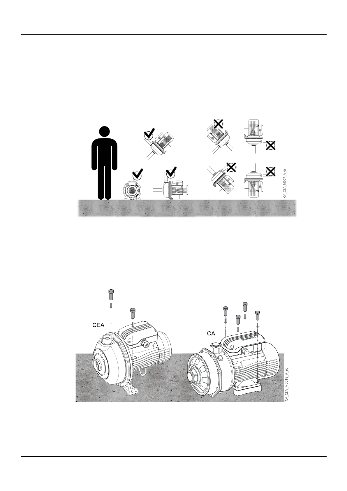
4.4 Permitted positions
4.5 Fastening
1. Place the unit on the foundation.
2. Using a spirit level, make sure that the unit is level.
3. Align the suction and discharge ports to their piping.
4. Secure the unit with bolts (2 or 4, depending on model).
5. If present, remove the plugs covering the suction and discharge ports.
The figure shows how to install the unit depending on the model.
4.6 Reducing vibrations
The motor and the flow of liquids in the system can generate amplified vibrations
from the possible incorrect installation of the unit and the piping. See Hydraulic connection.
20 CEA, CIE, CA series – Additional Installation, Operation and Maintenance Instructions
Page 21
4.7 Environments prone to condensation
NOTE:
If the plug is opened, the motor protection class becomes IP4X.
If the ambient temperature is higher than the liquid temperature, condensation may form
inside the motor during idle periods. To prevent the accumulation of condensation, open the
drain plug.
en - Original Instructions
Thermal insulation
Do not cover the motor adapter with thermal insulators so as not to trap the vapours released
by the mechanical seal, which can cause corrosion.
CEA, CIE, CA series – Additional Installation, Operation and Maintenance Instructions 21
Page 22
en - Original Instructions
5 Hydraulic connection
5.1 Preliminary operations
1. Flush the piping system before connecting them to the unit, to remove any welding
residue, deposits and impurities.
2. If a lifting device is used, for example a sling bar or hoist, provide sufficient space above the
unit.
3. Check the maximum operating pressure of piping system, joints, valves and expansion
vessels, which must be higher than the maximum pressure delivered by the unit on the
discharge side.
4. Do not install the unit at the lowest point of the system, to avoid the accumulation of
sediments.
5. Install an automatic relief valve at the highest point of the system to eliminate air bubbles.
6. If several units are used with the same liquid source, provide a suction pipe for each unit.
7. Support the piping system independently, so as not to burden the unit.
8. Install a prevention device to protect against the lack of liquid (float or probes) or a
minimum pressure device (pressure switch).
9. To reduce the transmission of vibrations between the unit and the system and vice versa,
install:
• anti-vibration joints on the suction and discharge sides of the unit; alternatively use
flexible pipes
• dampers between the unit and the surface on which it is installed.
5.2 Guidelines for the suction side
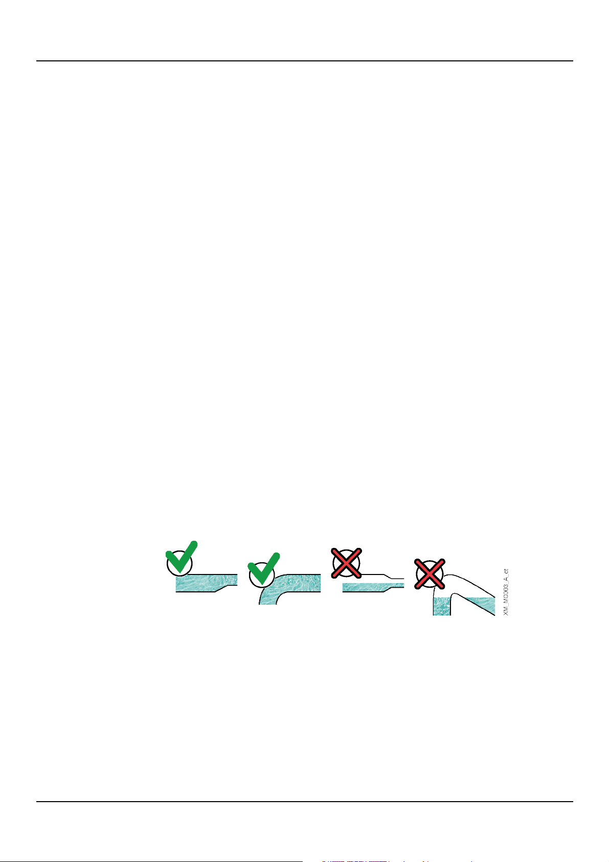
To reduce friction loss, the piping must be:
• As short and as straight as possible
• Without bottlenecks
• At least six times as long as the diameter of the suction port for the section connected to
the unit
• Wider than the suction port; if necessary, install an eccentric reducer with horizontal top
surface
• Without bends: if this cannot be avoided, with a radius as wide as possible
• Without traps and 'goosenecks'
• With valves with a low specific friction loss.
22 CEA, CIE, CA series – Additional Installation, Operation and Maintenance Instructions
Page 23
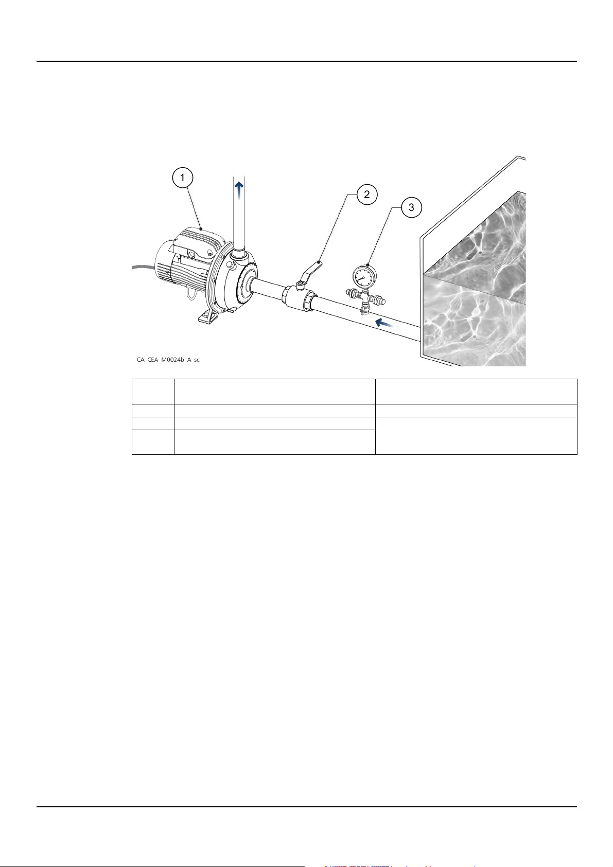
5.2.1 Positive suction head installation
Position
number
Name
Function
1
Unit 2
On-off valve
Isolate the unit in case of maintenance
3
Pressure gauge with pressure sensor (if fitted) and shut-off
valve
The installation is a positive suction head installation when the unit is below the suction water
source.
The figure shows an example of positive suction head installation.
en - Original Instructions
CEA, CIE, CA series – Additional Installation, Operation and Maintenance Instructions 23
Page 24
en - Original Instructions
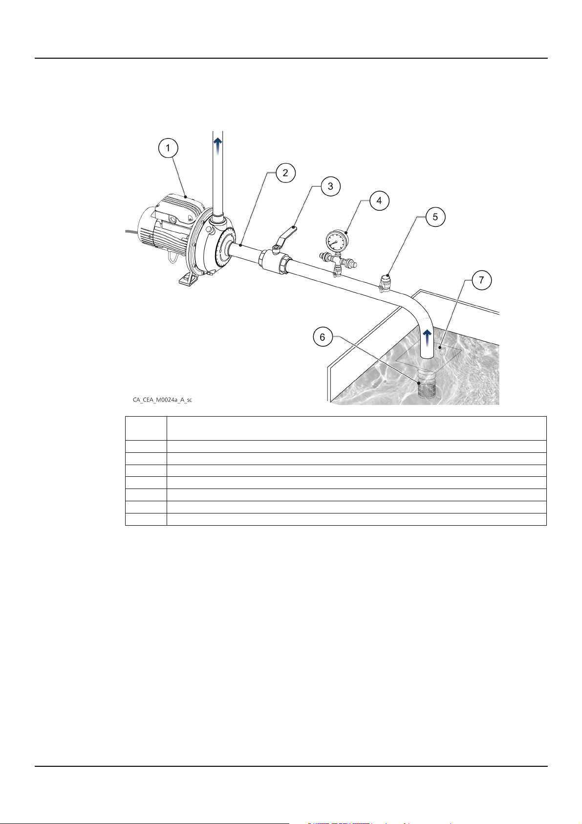
Position
number
Name
1
Unit 2 Piping system with increasing slope towards the unit exceeding 2% to avoid air pockets
3
On-off valve, to isolate the unit in case of maintenance
4
Hand-vacuum meter with pressure sensor (if fitted) and on-off valve, to also measure the negative operating pressure
5
Fill and relief valve
6
Foot valve and large-mesh filter
7
Vortex protection device, to prevent air from entering during the suction phase
5.2.2 Suction lift installation
The installation is a suction lift installation when the unit is above the suction water source.
The figure shows an example of suction lift installation.
24 CEA, CIE, CA series – Additional Installation, Operation and Maintenance Instructions
Page 25
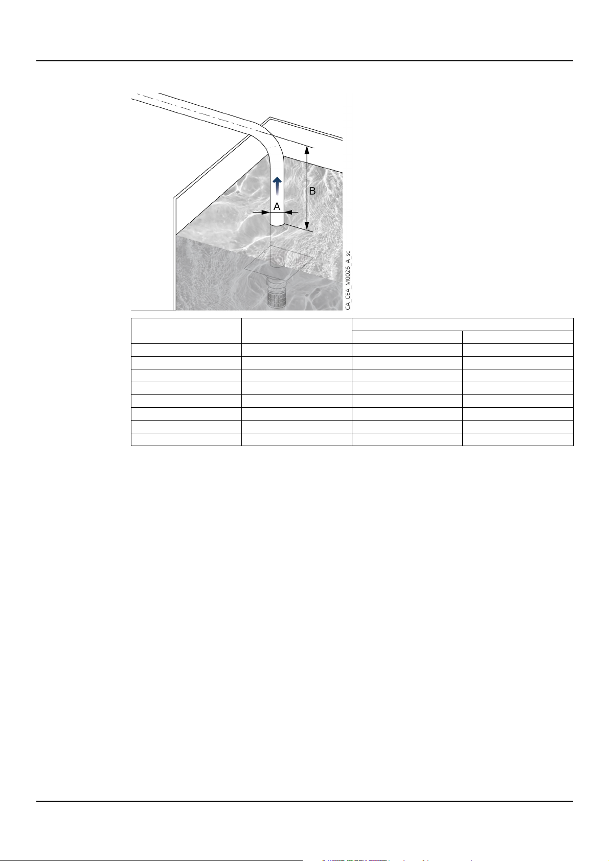
Indicative values of the suction level difference
Model
A - Minimum suction pipe
diameter, GAS inches
B - Suction level difference, m (ft)
With 50% flow rate
With 100% flow rate
CEA 70
1” 1/4
6 (20)
4 (13)
CEA 80
1” 1/4
5.5 (18)
3 (10)
CEA 120
1” 1/4
5 (16)
1.5 (5)
CEA 210
1” 1/2
5 (16)
1.5 (5)
CEA 370
2”
5.5 (18)
0.5 (2)
CA 70
1” 1/4
6.5 (21)
3 (10)
CA 120
1” 1/4
6 (20)
2.5 (8)
CA 200
1” 1/2
7.5 (25)
5 (16)
en - Original Instructions
Note
Level difference values calculated using a piping system:
• Total length 10 m for 50% flow rate and 5 m for 100% flow rate
• With a single 90° bend
• With a foot valve.
5.3 Guidelines for the discharge side
On the discharge side install:
• A check valve to prevent the liquid from flowing back into the unit when this is at a
standstill
• A pressure gauge fitted with an on-off valve, after the non-return valve, to check the
actual operating pressure of the unit
• A pressure sensor after the non-return valve, equipped with an on-off valve, in case of
constant pressure operation
• An expansion vessel after the non-return valve, equipped with an on-off valve
• A shut-off valve at the end of the system to isolate the unit in case of maintenance and to
regulate the flow rate.
CEA, CIE, CA series – Additional Installation, Operation and Maintenance Instructions 25
Page 26
en - Original Instructions
NOTE:
The control panel must match the ratings on the unit data plate. Improper combinations could
damage the motor.
Unit type
Protection
Single phase standard ≤ 1.5 kW
• Automatic reset thermal-ampere protection, in-built (motor protector)
Short circuit, must be supplied by the installer.1
Three-phase and single-phase2
•
• Short circuit, must be supplied by the installer.
NOTE:
Refer to the current shown on the data plate for the selection of the protective device and
comply with local and national regulations for its sizing.
WARNING: Injuries hazard
The unit, equipped with a single
protection, could restart inadvertently after it has cooled down: risk of physical injury.
6 Electrical connection
6.1 Guidelines for electrical connection
1. Check that the electrical leads are protected against:
• High temperature
• Vibrations
• Collisions
• Liquids.
2. Check that the power supply line is provided with:
• A short circuit protection device of appropriate size
• A mains disconnection device with contact opening distance ensuring complete
disconnection for overvoltage III category conditions.
6.2 Guidelines for the control panel
1. Fit a system for protection against dry running to which to connect a pressure switch, or a
float, probes or other suitable devices.
2. On the suction side install:
• A pressure switch, in the case of connection to the mains water supply
• A float switch or probes, in the case of liquid drawn from a tank or basin.
3. When thermal relays are used, the type sensitive to phase failure is recommended.
4. Install a suitable device (thermal relay or motor protector, see table below) to protect the
motor from overloads and short circuits:
6.3 Motor connection
•
Thermal, must be supplied by the installer
-phase motor with automatic reset thermal overload
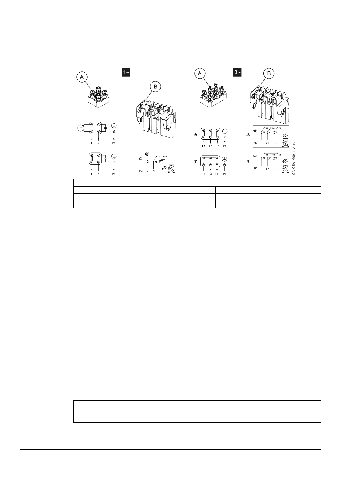
1. Open the terminal box cover.
2. Connect the power supply conductor; see the figure below or the wiring diagram shown
inside the terminal box cover.
3. Connect the protection conductor (ground), making sure that it is longer than the phase
conductors.
1
Fuses aM (motor starting), or magneto-thermal switch with curve C and Icn ≥ 4.5 kA or other equivalent device.
2
Trip class 10 A overload thermal relay + aM fuses (motor start), or start class 10 A motor protection thermal magnetic switch.
26 CEA, CIE, CA series – Additional Installation, Operation and Maintenance Instructions
Page 27
en - Original Instructions
A
B
Wrench, mm
M4
M5
M6
M8
M10
-
Tightening torque,
Nm (lbf·in)
1,2 (11)
2,5 (22)
4,0 (35)
8,0 (71)
15,0 (133)
1,2 (11)
Motor size
Voltage peak, V
dV/dt, V/μs
up to 90R (500 V)
< 650
< 2200
from 90R to 180R
< 1400
< 4600
4. Connect the phase leads.
5. Close the terminal box cover and tighten all the screws and cable glands.
The figure shows the terminal box types and the electrical connection.
6. Check the direction of rotation, following the procedure in Checking the direction of
rotation.
Motor without automatic reset thermal overload protection
1. If the motor is used with full load, then set the value to the nominal current value on the
data plate of the unit.
2. If the motor is used with partial load, then set the value of the operating current measured
with a current pincer.
3. For three-phase motors with star-delta starting system, set the thermal relay downstream of
the switching circuit at 58% of the rated or operating current.
6.4 Operation with frequency converter
The motors can be connected to a frequency converter for speed control.
• The converter exposes the motor insulation to a higher load, which is influenced by the
length of the connecting cable. In this case, it is advisable to install a dV/dt or sinusoidal
filter.
• Filters extend the life of the motor.
• The inductance on the motor side (dV/dt filter) reduces the dV/dt value on the rising edge
and phases, levelling out the current waveform.
• The sinusoidal filter takes both the waveform of the current and the waveform of the voltage
to the output of the sinusoidal frequency converters.
• Comply with the frequency converter manufacturer's instructions.
• The bearings of the motors, from size 315 S/M and up, are exposed to the risk of harmful
currents: use electrically insulated bearings.
• The conditions of installation must guarantee protection against voltage peaks between the
terminals and/or dV/dt in the table:
CEA, CIE, CA series – Additional Installation, Operation and Maintenance Instructions 27
Page 28
en - Original Instructions
WARNING: Injuries hazard
Ensure that electrical protection is installed, where required: risk of personal injury.
WARNING:
Make sure that the
WARNING:
In the case of liquids that are excessively hot or cold, pay attention to the risk of injury.
WARNING:
It is prohibited to operate the unit when dry, not primed and below the rated flow rate.
WARNING:
It is prohibited to operate the unit with the on
WARNING:
Observe the limits given on the data plate for the operation of
WARNING: Electrical hazard
Check that the unit is properly connected to the mains power supply.
WARNING: Hot surface hazard
Beware of the high temperature produced by the unit and motor.
WARNING:
It is prohibited to place
NOTE:
Check that the shaft can turn smoothly.
NOTE:
It is prohibited to use the unit in the case of cavitation.
7 Use and operation
7.1 Precautions
Before starting the unit, check that the instructions in chapter Mechanical installation have
been followed correctly.
drained liquid cannot cause damage or injuries.
-off valves closed.
the unit.
flammable materials near the unit.
28 CEA, CIE, CA series – Additional Installation, Operation and Maintenance Instructions
Page 29
NOTE:
The unit must be filled and vented properly before it can be started.
NOTE:
The maximum pressure delivered by the unit on the discharge side, influenced by the available
pressure on the suction side, must be lower than the maximum operating pressure.
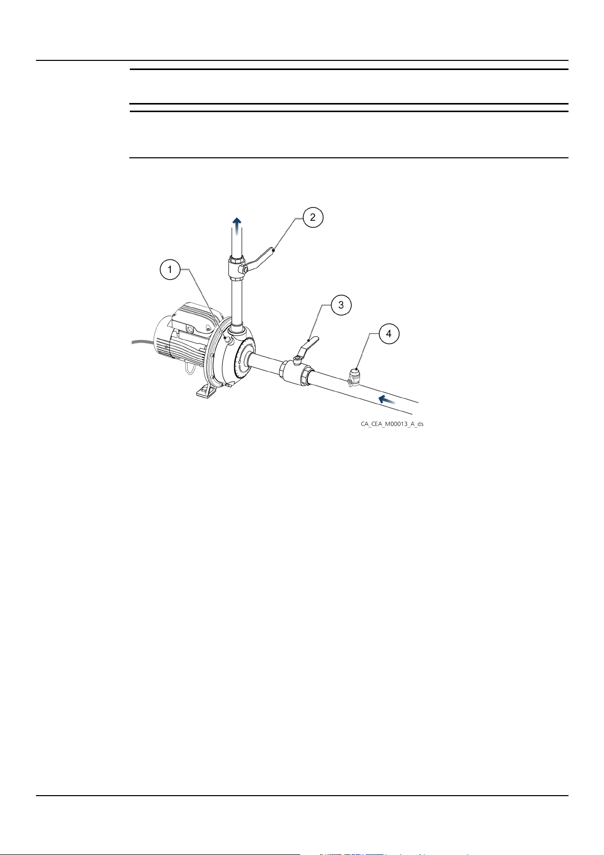
7.2 Filling and priming
en - Original Instructions
1. Filling plug
2. On-off valve on discharge line
3. On-off valve on suction line
4. Fill and relief valve
Positive suction head installation
1. Close both on-off valves.
2. Loosen the filler cap.
3. Slowly open the suction on-off valve until liquid flows evenly out of the filling hole; if
necessary, loosen the cap further.
4. Tighten the cap.
Tightening torque: 8 Nm (70 lbf·in) ± 25%.
5. Open both the on-off valves slowly and fully.
Suction lift installation
1. Open the on-off valve at the suction.
2. Shut the on-off valve located on the discharge line.
3. Remove the filler cap.
4. Partially open the filling valve.
5. Fill the unit from the filling hole and fill the suction piping from the filling valve.
6. Wait until the liquid flows out of the unit and add more liquid if necessary.
7. Close the filler cap.
Tightening torque: 8 Nm (70 lbf·in) ± 25%.
8. Close the filling valve.
9. Slowly fully open the on-off valve on the discharge side.
CEA, CIE, CA series – Additional Installation, Operation and Maintenance Instructions 29
Page 30
en - Original Instructions
NOTE:
Do not remove the protections during the entire direction
NOTE:
It is prohibited to operate the unit with the on
damage due to overheating of the liquid.
NOTE:
If there is a risk of
circuit.
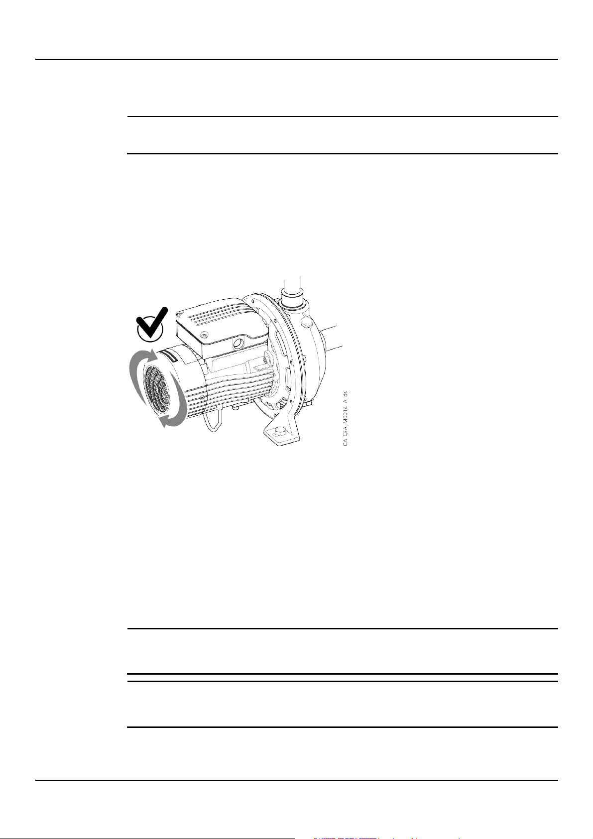
7.3 Checking the direction of rotation (three-phase motor)
Before starting the unit:
check.
1. Stand on the side of the motor cooling fan.
2. Locate the arrows on the fan cover.
3. Start the unit and run it for a few seconds.
4. Check the rotation direction of the motor. The rotation of the motor must be as pointed by
the arrows.
5. In case of incorrect rotation direction:
• stop the unit
• follow the procedure indicated in the next chapter
6. Repeat the check from step 3.
If the direction of rotation is wrong and the unit is equipped with a single-phase motor, contact
Xylem or the Authorised Distributor.
7.3.1 Wrong rotation direction (three-phase motor)
1. Disconnect the power supply.
2. Invert two of the three wires of the power cable in the terminal box of the motor or in the
control electric panel.
3. Connect the power supply.
4. Start the unit.
5. Check the rotation direction through the motor cover.
6. Stop the unit.
7.4 Startup
-off valves closed or at zero flow rate: risk of
the unit running at a flow rate below the minimum expected, install a bypass
30 CEA, CIE, CA series – Additional Installation, Operation and Maintenance Instructions
Page 31
Preliminary operations
WARNING:
After startup, run the unit for a few minutes with several users open in order to
wash the inside of the system.
en - Original Instructions
Before starting the unit, check that all the operations listed in
completed correctly.
Check the pre-charge of the expansion vessel
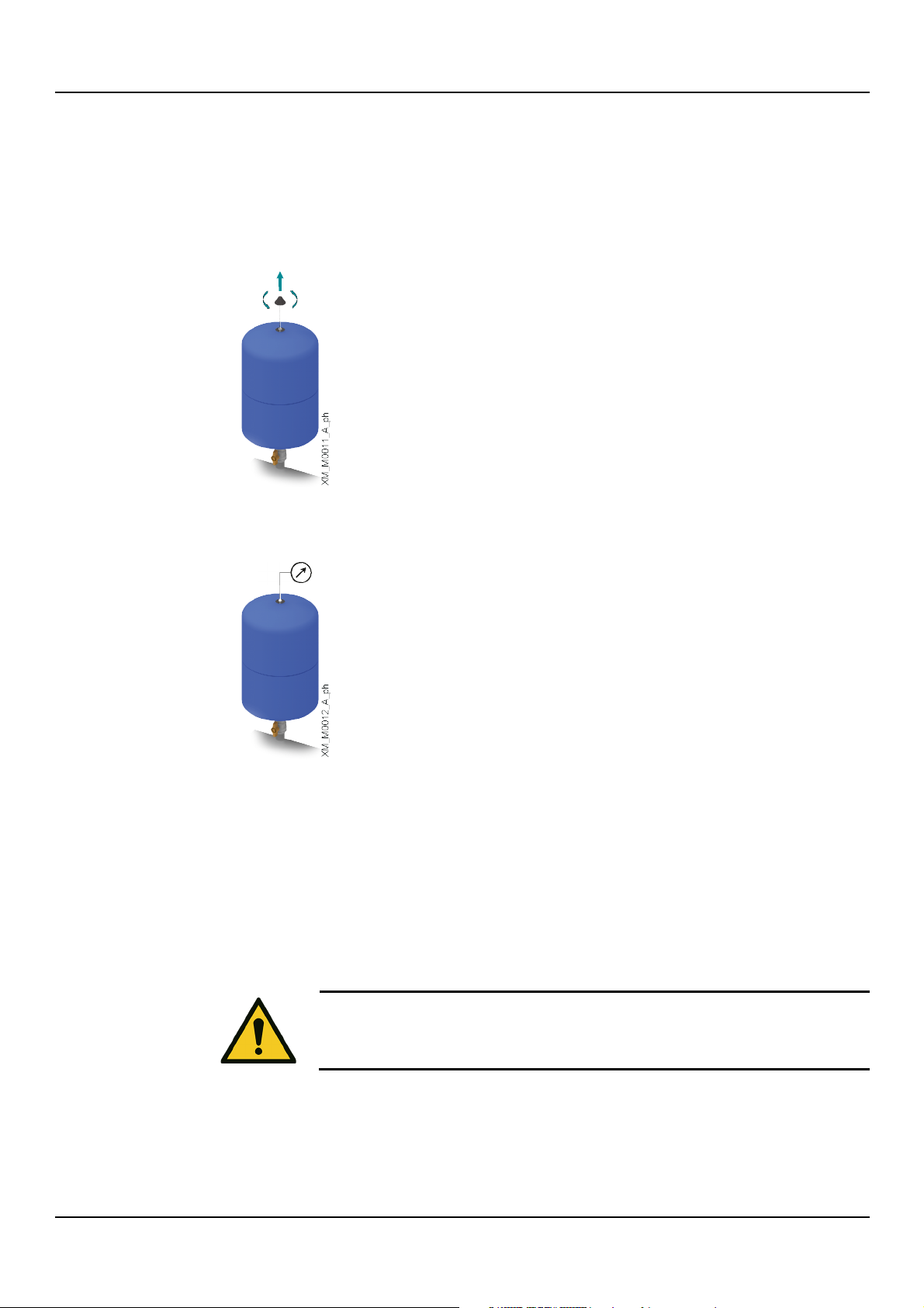
1. Check that the pressure of the system is zero, to avoid affecting the reading of the pressure
gauge.
2. Unscrew the valve cap.
3. Attach the pressure gauge to the valve and charge the vessel to the desired pre-charge
pressure. Pre-charge pressure = unit start pressure - 0.3 bar.
Filling and priming have been
4. Remove the pressure gauge and screw the cap.
Startup
1. Close the on-off valve on the discharge side almost completely.
2. Fully open the suction on-off valve.
3. Start the unit.
4. Gradually open the on-off valve on the discharge side to half way.
5. Wait a few minutes and then open it completely.
6. Check the pressure gauge and ensure that the unit quickly reaches the correct pressure.
Final operations
After the start-up procedure, with the pump unit in operation, check that:
• No liquid is leaking from the unit or pipes
• The maximum pressure of the unit at the discharge, determined by the available suction
pressure, does not exceed the maximum operating pressure
• The current absorbed is within the rated limits (calibrate the thermal overload protection of
the motor).
CEA, CIE, CA series – Additional Installation, Operation and Maintenance Instructions 31
Page 32

en - Original Instructions
NOTE:
If the unit does not deliver the required pressure, repeat the operations in
priming.
• There is no unwanted noise or vibrations
• No vortexes form at the end of the suction pipe (suction lift installation)
• The devices to prevent the absence of liquid (float or probes), or the minimum pressure
devices work correctly
• With zero flow rate the unit stops automatically
• When the unit is stationary, it does not turn in the wrong direction due to a liquid backflow
through the non-return valve
• The minimum flow rate in continuous operation is not less than the values indicated in the
electrical specifications of the unit.
Settling of the mechanical seal
The pumped liquid lubricates the seal faces of the mechanical seal; under normal conditions, a
small amount of liquid may leak out. When the unit is run for the first time, or immediately after
the seal is replaced, more liquid may temporarily leak out.
To help the seal settle and to reduce leaking:
1. Close and open the on-off valve on the discharge side two or three times with the unit
running.
2. Stop and start the unit two or three times.
Filling and
7.5 Stopping the unit
1. Slowly close the discharge on-off valve.
2. Stop the unit and check that it actually stops.
3. Gradually re-open the on/off valve and check that the motor remains still.
32 CEA, CIE, CA series – Additional Installation, Operation and Maintenance Instructions
Page 33
8 Maintenance
DANGER: Electrical hazard
Before starting work, check that the electric power supply is disconnected and locked out, to
avoid unintentional restart of the unit, the control panel and the auxiliary control circuit.
DANGER: Electrical hazard
If the unit is combined with a
wait 10 min to discharge the residual current.
WARNING:
Always use suitable working tools.
WARNING:
In the case of liquids that are excessively hot or cold, pay attention to the risk of
8.1 Precautions
Before starting any work, make sure to read and understand all the safety instructions in
Introduction and Safety.
frequency converter, disconnect the power supply and
en - Original Instructions
8.2 Maintenance every 4000 hours of operation, or every year
Perform the following operations when the first of the two limits is reached:
Check that:
• No liquid is leaking from the unit or piping system
• There is no unwanted noise or vibrations
• The devices to prevent the absence of liquid (float or probes), or the minimum pressure
devices work correctly
• The unit does not remain in operation with zero flow rate
• When the unit is stationary, it does not turn in the wrong direction due to a liquid
backflow through the non-return valve.
Maintenance with the unit switched off and disconnected from the power supply
Check:
• The status of the power supply cable and control panel of the unit
• That there are no signs of overheating and electric arcs on the terminal boxes and traces
of humidity inside the terminal box
• The pre-charge of the expansion vessel (see the instructions in Startup)
• The cleanliness of the fan cover and stator case
• The status of the cooling fan.
injury.
8.3 Maintenance every 10000 hours of operation or every 2 years
When the first of the two limits is reached, replace the mechanical seal and the o-rings.
Contact Xylem or the Authorised Distributor for further technical information.
8.4 Maintenance every 17500 hours of operation or every 5 years
When the first of the two limits has been reached, replace the permanently lubricated bearings
of the motor, if present.
CEA, CIE, CA series – Additional Installation, Operation and Maintenance Instructions 33
Page 34

en - Original Instructions
8.5 Long periods of inactivity
1. Shut the suction and discharge on-off valves.
2. Follow the instructions in Storage.
3. Before starting the unit, check the status of the connections of the electric conductors on
the unit and the control panel.
4. Start the unit following the instructions in Startup.
8.6 Identification of spare parts
Identify the spare parts with the product codes directly on the site spark.xylem.com.
Contact Xylem or the Authorised Distributor for further technical information.
34 CEA, CIE, CA series – Additional Installation, Operation and Maintenance Instructions
Page 35

9 Troubleshooting
WARNING:
If a fault cannot be corrected or is not mentioned, contact Xylem or the Authorised Distributor.
Cause
Solution
Electric power supply cut off
Reset the power supply
The residual current protection device (RCD) has tripped
Reset the protection device
The thermal overload protection of the motor has tripped
Reset the thermal protection
The device that detects the absence of liquid has tripped
Restore the liquid level
The minimum pressure device has tripped
Restore the minimum pressure
The starter of the unit does not work
Repair the device
Faulty unit starter
Replace the device
Damaged or defective power supply cable or joint
Repair or replace the cable
Faulty capacitor
Replace the capacitor
Control panel faulty
Check and repair or replace the control panel
Contact Xylem or the Authorised Distributor, or send the unit to an
authorised workshop
Cause
Solution
Unit not primed
•
• Check the suction conditions
On-off valve on discharge line closed
Open the valve
Non-return valve installed in the wrong direction
Reinstall the valve correctly
Check valve locked in the partially closed position
Repair or replace the valve
Suction filter clogged
Clean the filter
Clogged piping system
Remove the clogging
Liquid leaks from the piping system
Identify the leaks and repair the piping system
System with excessive friction losses
Replace the piping and/or fittings with some of a larger diameter or with a
lower specific friction losses
Foreign bodies in the unit
Remove foreign bodies or contact Xylem or the Authorised Distributor, or
send the unit to an authorised workshop
Three-phase motor turning in the wrong direction
Swap two of the three power supply phases
Unit in cavitation
Increase the available NPSH (net positive suction head)
Undersized unit
Contact Xylem or the Authorised Distributor, or send the unit to an
authorised workshop.
Unit faulty
Contact Xylem or the Authorised Distributor, or send the unit to an
authorised workshop
Before starting any work, make sure to read and understand all the safety instructions in
Introduction and Safety.
9.1 The unit does not switch on
en - Original Instructions
Unit faulty
9.2 Little or no hydraulic performance
Bleed the unit
• Increase the liquid level in the suction tank
• Remove any turbulences of the liquid in the suction area
CEA, CIE, CA series – Additional Installation, Operation and Maintenance Instructions 35
Page 36
en - Original Instructions
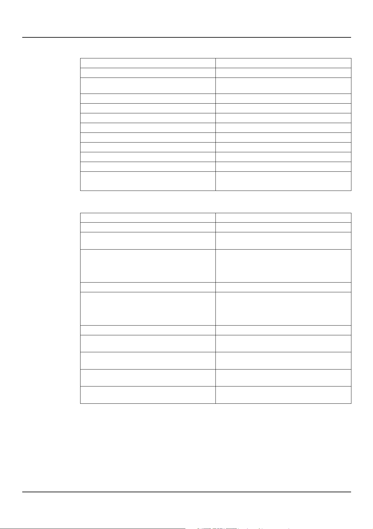
Cause
Solution
Expansion vessel missing
Install an expansion vessel
Expansion vessel too small
•
• Replace the vessel with a larger one
Expansion vessel empty
Pre-charge the vessel correctly
Expansion vessel faulty
Replace the vessel
Starter incorrectly calibrated
Adjust the device calibration
Starter faulty
Replace the device
Incorrectly installed level probes
Install the probes correctly
Faulty level probes
Replace the probes
Liquid leaks from the piping system
Identify the leaks and repair the piping system
Check valve faulty or defective
Replace the valve
Oversized unit
Contact Xylem or the Authorised Distributor, or send the unit to
Cause
Solution
Plant resonance
Check the installation of the unit
Foreign bodies in the unit
Remove foreign bodies or contact Xylem or the Authorised
Distributor, or send the unit to an authorised workshop
Water hammer
•
off valve before shutting down the unit,
Power the unit through a soft starter
Unit in cavitation
Increase the available NPSH (net positive suction head)
Unit not primed
•
• Check the suction conditions
Unit wrongly anchored to the foundations
Check the unit anchoring
Anti-vibration joints on the piping system not suitable and/or
absent
Install or check the anti-vibration
Motor bearings worn or faulty
Replace the motor bearings or contact Xylem or the Authorised
Distributor, or send the unit to an authorised workshop
The unit does not turn freely due to a mechanical fault
Contact Xylem or the Authorised Distributor, or send the unit to an
authorised workshop
Unit faulty
Contact Xylem or the Authorised Distributor, or send the unit to an
authorised workshop
9.3 The unit starts and stops too frequently
Add another vessel to the system or
an authorised workshop
9.4 The unit produces excessive noise and/or vibrations
Close the discharge onor
• Install an expansion vessel in the system, or
•
Bleed the unit
• Increase the liquid level in the suction tank
• Remove any turbulences of the liquid in the suction area
36 CEA, CIE, CA series – Additional Installation, Operation and Maintenance Instructions
Page 37
9.5 The unit is leaking at the mechanical seal
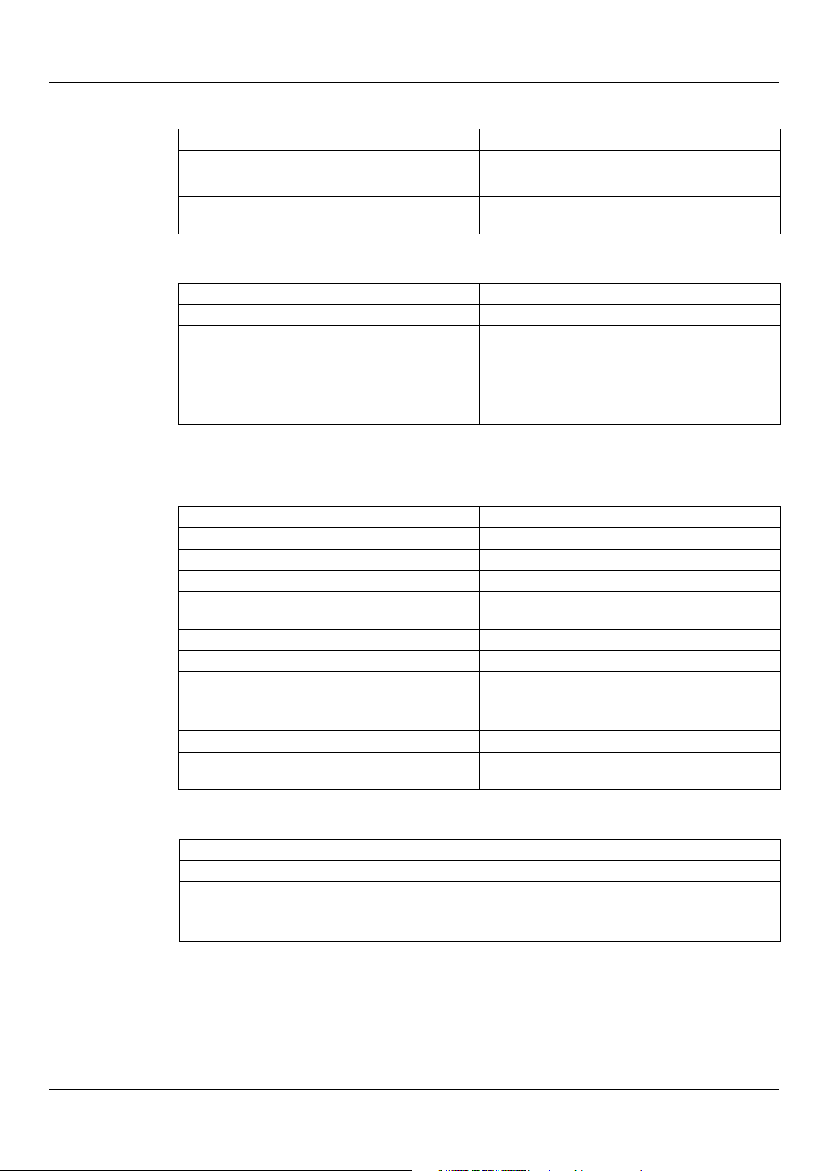
Cause
Solution
Initial settling/running in of the mechanical seal
Carry out the procedure to help the mechanical seal settle (see
Seal damaged or worn
Replace the seal or contact Xylem or the Authorised Distributor, or
send the unit to an authorised workshop
Cause
Solution
Cooling fan of the motor clogged or damaged
Clean or replace the cooling fan
Incorrectly calibrated frequency converter (if present)
See the frequency converter manual
Room temperature too high, exposure to sunlight
• Check the ambient temperature
Protect the unit from sunlight
Unit faulty
Contact Xylem or the Authorised Distributor, or send the unit to an
authorised workshop
Cause
Solution
Incorrectly calibrated thermal protection
Adjust the calibration of the thermal protection
Input voltage outside the rated limits
Ensure correct voltage values
Motor phase missing
Ensure correct voltage values
Decrease the flow rate by partially closing the on-off valve on the
discharge side
Liquid too thick
Decrease the density of the liquid
Solid or fibrous materials in the liquid
Remove the materials from the liquid
Thermal protection and/or fuses in the control panel exposed to
high temperatures or sunlight
Loose electrical connections
Check that the electrical connections are tight
Damaged or defective power supply cable or joint
Repair or replace the cable
Contact Xylem or the Authorised Distributor, or send the unit to an
authorised workshop
Cause
Solution
Unsuitable residual current protection device
Replace the device with a suitable one
Residual current protection device faulty
Replace the device
Unit faulty
Contact Xylem or the Authorised Distributor, or send the unit to an
authorised workshop
chapter Startup)
9.6 The motor becomes excessively hot
•
9.7 Tripping of the thermal motor protection
en - Original Instructions
The motor thermal overload protection triggers occasionally, or after the unit has been
running for a few minutes.
The unit operates with an excessive flow rate
Protect the control panel; refer to the control panel manual
Unit faulty
9.8 The residual current protection device (RCD) has tripped
CEA, CIE, CA series – Additional Installation, Operation and Maintenance Instructions 37
Page 38
en - Original Instructions
NOTE:
If the unit is exposed to:
•
•
above the permitted ones, contact Xylem or the Authorised Distributor.
NOTE: Danger of motor overheating
If the unit is installed at an altitude:
•
•
The motor power reduction percentage refers to the permitted unit operating temperature.
Type of gasket
Min. - max. temperature, °C (°F)
Max. pressure, bar (psi)
NBR
-10 (14) ÷ 85 (185)
8 (116 psi)
FPM
-10 (14) ÷ 110 (230)
-10 (14) to 80 (176) with water
EPDM
-10 (14) ÷ 110 (230)
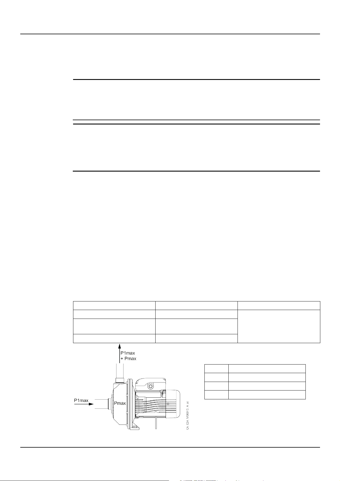
Data
Description
P1max
Maximum input pressure
Pmax
Maximum pressure generated by the unit
PN
Maximum operating pressure
P1max + Pmax ≤ PN
10 Specifications
10.1 Operating environment
Temperature
Humidity
Between 1500 and 2000 m (4900 to 6600 ft), reduce the power of the motor by 5%, or
replace it with a more powerful one
Above 2000 (6600), contact Xylem or the Authorised Distributor
Atmosphere
Non-aggressive and non-explosive.
Temperature
-15 to 45°C (5 to 113°F), with single-phase motor
-15 to 40°C (5 to 104°F), with three-phase motor
Relative air humidity
< 50% at 40°C (104°F).
Elevation
< 1000 m (3280 ft) above sea level.
10.2 Operating temperature and pressure
The table shows the permissible liquid temperature and pressure limits, depending on the seal
type.
38 CEA, CIE, CA series – Additional Installation, Operation and Maintenance Instructions
Page 39
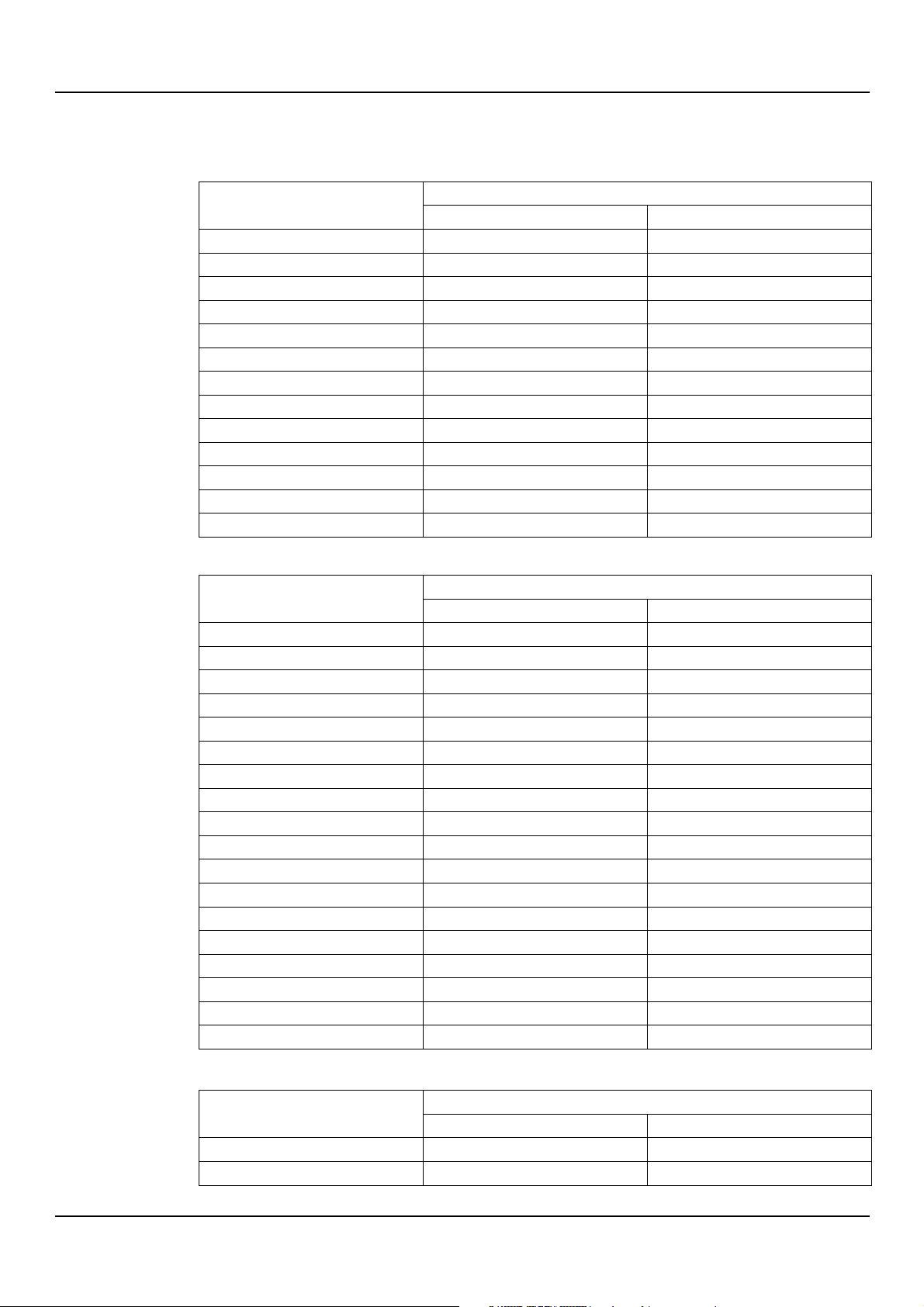
10.3 Maximum head
Model
Max. head, m (ft)
Single-phase
Three-phase
70/3
22 (72)
22 (72)
70/5
32 (105)
31 (102)
80/5
33 (108)
32 (105)
120/3
22 (72)
22 (72)
120/5
32 (105)
32 (105)
210/2
18 (59)
18 (59)
210/3
21 (69)
21 (69)
210/4
26 (85)
26 (85)
210/5
-
29 (95)
370/1
16 (52)
16 (52)
370/2
20 (66)
20 (66)
370/3
-
24 (79)
370/5
-
30 (98)
Model
Max. head, m (ft)
Single-phase
Three-phase
706/3
33 (108)
32 (105)
706/4
-
39 (128)
706/5
-
45 (148)
1206/1
22 (73)
22 (73)
1206/2
28 (91)
28 (91)
1206/3
-
33 (108)
1206/4
-
40 (131)
1206/5
-
47 (154)
2106/0
17 (56)
17 (56)
2106/1
-
21 (69)
2106/2
-
25 (82)
2106/3
-
30 (98)
2106/4
-
35 (115)
3706/0
-
17 (56)
3706/0A
-
20 (66)
3706/1
-
24 (79)
3706/2
-
30 (98)
3706/3
-
35 (115)
Model
Max. head, m (ft)
Single-phase
Three-phase
70/33
44 (144)
43 (141)
70/34
49 (161)
48 (157)
10.3.1 CEA and CIE series
en - Original Instructions
60 Hz motors
10.3.2 CA series
CEA, CIE, CA series – Additional Installation, Operation and Maintenance Instructions 39
Page 40
en - Original Instructions
70/44
52 (171)
-
70/45
-
58 (190)
120/33
45 (148)
44 (144)
120/34
49 (161)
-
120/35
-
55 (180)
120/55
-
63 (207)
200/33
-
43 (141)
200/35
-
53 (174)
200/55
-
63 (207)
Model
Max. head, m (ft)
Single-phase
Three-phase
706/33
-
63 (207)
1206/33
-
64 (210)
2006/33
-
64 (210)
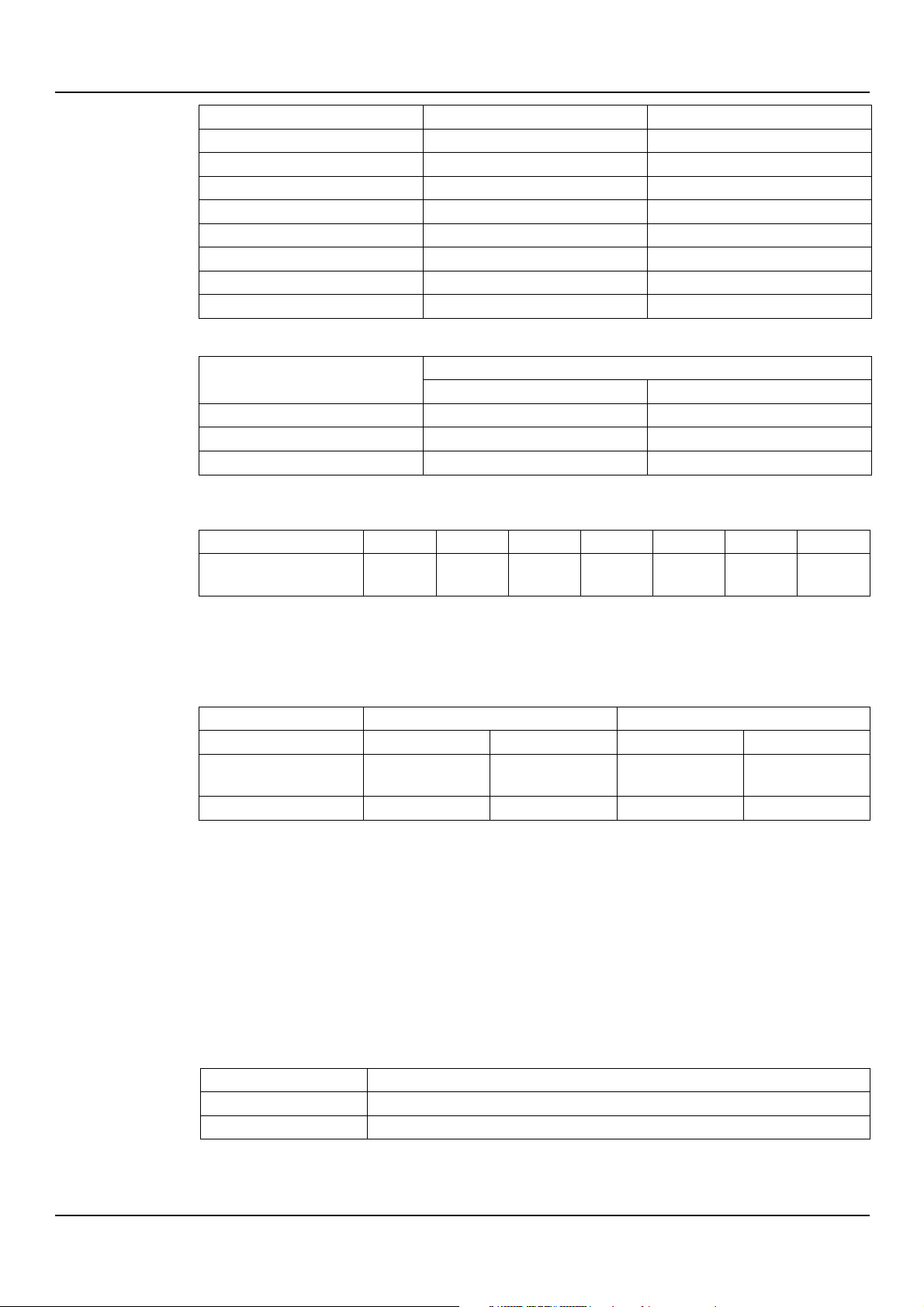
Unit rated power, kW
0,25÷3
4÷7,50
11÷15
18,5÷22
30÷37
45÷75
90÷160
No. of start-ups at regular
intervals per h
60
40
30
24
16 8 4
Frequency Hz
50
60
Phase
1~
3~
1~
3~
UN [V] ± %
220÷240± 6
230/400 ± 10
400/690 ± 10
220÷230 ± 6
220/380 ± 5
380/660 ± 10
No. of conductors + ground
2+1
3+1
2+1
3+1
Model
Material
CEA, CIE, CA
Stainless steel/AISI 304
CEA..N, CA..N
AISI 316L stainless steel
60 Hz motors
10.4 Maximum number of starts and stops
10.5 Electrical specifications
See the motor data plate.
Permitted tolerances for the supply voltage
Protection class
Motor: IP55
Electric pump: IPX5
For possible condensation inside the motor, see Environments prone to condensation.
10.6 Sound pressure
< 70 dB (A), measured in free field, at a distance of one metre from the unit, during no-load
operation at 3600 rpm.
10.7 Materials in contact with the liquid
40 CEA, CIE, CA series – Additional Installation, Operation and Maintenance Instructions
Page 41
11 Disposal
WARNING:
The unit must be disposed of through approved companies specialised in the identification of
different types of materials: steel, copper, plastic, lithium, ferrite etc...
WARNING:
It is prohibited to dispose of
environment.
11.1 Precautions
11.2 WEEE (EU/EEA)
INFORMATION TO USERS pursuant to art. 14 of the Directive 2012/19/EU of the European
Parliament and of the Council of 4 July 2012 on waste electrical and electronic equipment
(WEEE). The crossed bin symbol on the appliance or on its packaging indicates that the
product at the end of its useful life must be collected separately and not disposed of together
with other mixed urban waste. Appropriate separate collection for the subsequent start-up of
the disused equipment for recycling, treatment and environmentally compatible disposal
helps to avoid possible negative effects on the environment and on health and favours the reuse and / or recycling of the materials of which the equipment is composed.
en - Original Instructions
lubricating fluids and other hazardous substances in the
WEEE from private households (Classification according to product type, use and current local
laws): please contact your municipality, or local authority, for all information regarding the
separate collection systems available in the area. The retailer is obliged to collect the old
equipment free of charge when buying new equipment of an equivalent type, for the purpose
of starting the correct recycling / disposal.
WEEE from users other than private households (Classification according to product type, use
and current local laws): the separate collection of this equipment at the end of its life is
organized and managed by the produce (Producer of EEE as per Directive 2012/19/EU). The
user who wants to get rid of this equipment can then contact the producer and follow the
system that it has adopted to allow the separate collection of equipment at the end of life or
select an organization independently authorized to manage waste.
CEA, CIE, CA series – Additional Installation, Operation and Maintenance Instructions 41
Page 42
en - Original Instructions
11.3 WEEE (UK)
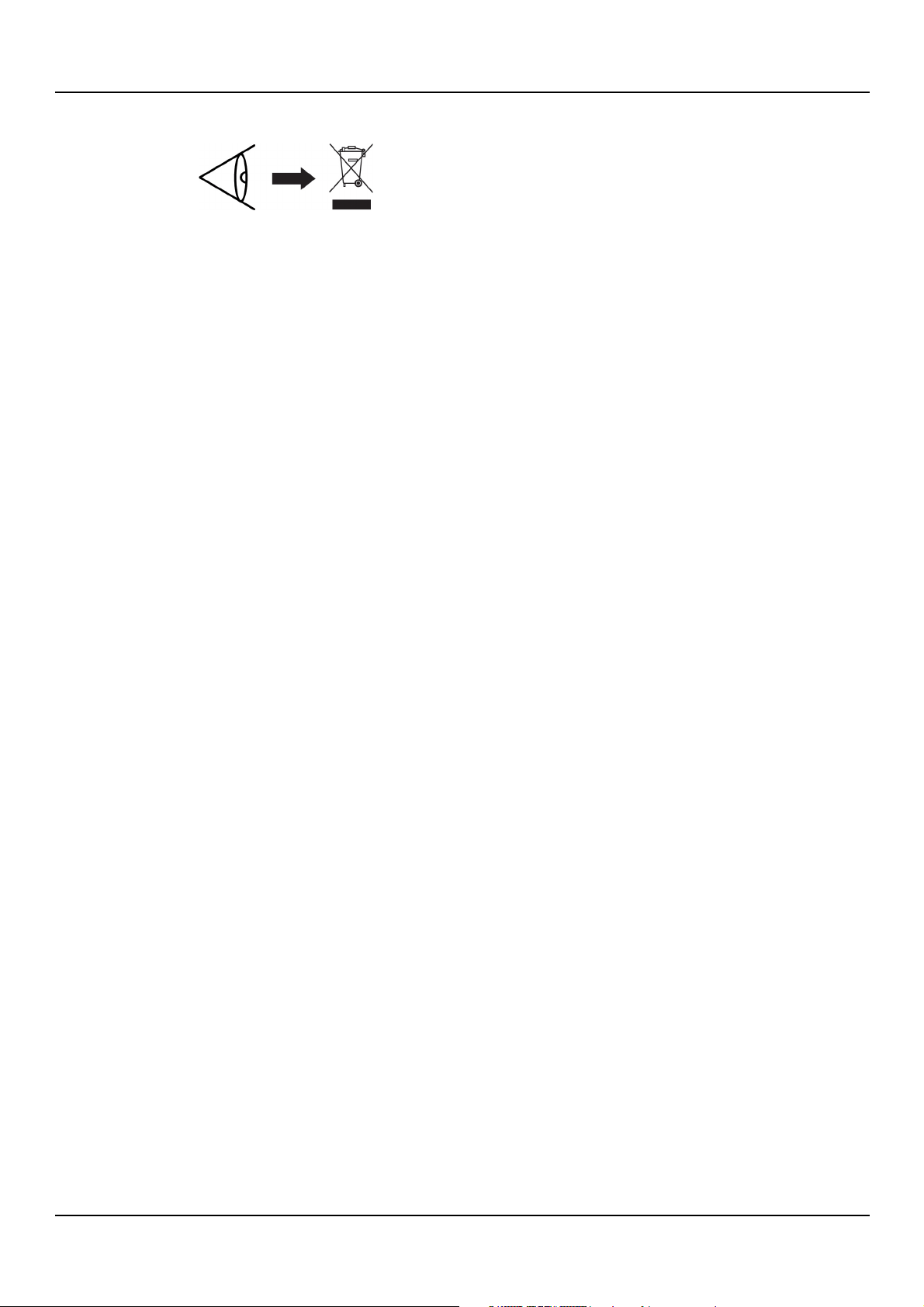
INFORMATION TO USERS pursuant to art. 44 of the The Waste Electrical and Electronic
Equipment Regulations 2013 (S. I. 2013 No. 3113). The crossed bin symbol on the appliance or
on its packaging indicates that the product at the end of its useful life must be collected
separately and not disposed of together with other mixed urban waste. Appropriate separate
collection for the subsequent start-up of the disused equipment for recycling, treatment and
environmentally compatible disposal helps to avoid possible negative effects on the
environment and on health and favours the re-use and / or recycling of the materials of which
the equipment is composed.
WEEE from private households (Classification according to product type, use and current local
laws): please contact your municipality, or local authority, for all information regarding the
separate collection systems available in the area. The retailer is obliged to collect the old
equipment free of charge when buying new equipment of an equivalent type, for the purpose
of starting the correct recycling / disposal.
WEEE from users other than private households (Classification according to product type, use
and current local laws): the separate collection of this equipment at the end of its life is
organized and managed by the producer (Producer of EEE as per WEEE Regulations 2013).
The user who wants to get rid of this equipment can then contact the producer and follow the
system that it has adopted to allow the separate collection of equipment at the end of life or
select an organization independently authorized to manage waste.
42 CEA, CIE, CA series – Additional Installation, Operation and Maintenance Instructions
Page 43
12 Declarations
rev.00
Refer to the specific declaration relating to the marking on the product.
en - Original Instructions
12.1 Electric pump
EC Declaration of Conformity (Original)
Xylem Service Italia S.r.l., with headquarters in Via Vittorio Lombardi 14 - 36075 Montecchio
Maggiore VI - Italy, hereby declares that the product:
CEA…or CIE…or CA … electric pump (see label on the last page of “Safety and Other
Information” manual)
fulfils the relevant provisions of the following European Directives
• Machinery 2006/42/EC and subsequent amendments (ANNEX II - natural or legal person
authorised to compile the technical file: Xylem Service Italia S.r.l.).
• Eco-design 2009/125/EC and subsequent amendments, Regulation (EU) 2019/1781 and
subsequent amendments (electric motor, if IE2, IE3 or IE4 marked), Regulation (EU) No
547/2012 and subsequent amendments (water pump, if MEI marked)
and technical standards
1 ~ ≤ 250 V, 3 ~ ≤ 480 V: EN 60335-1:2012+A11:2014
• U
N
+A13:2017+A14:2019+A1:2019+A2:2019+ A15:2021+A16:2023,EN IEC 60335-241:2021+A11:2021, EN 62233:2008.
1 ~ > 250 V, 3 ~ > 480 V: EN 60204-1:2018.
U
N
• EN 60034-30:2009, EN 60034-2-1:2007, EN 60034-30-1:2014, EN 60034-2-1:2014, EN
16480:2021.
Montecchio Maggiore, 10/02/2025
Alessio Vendraminelli
Managing Director
EU Declaration of Conformity (No 79)
1. EMCD - Apparatus/Product model: CEA…or CIE…or CA … electric pump (see label on the
last page of “Safety and Other Information” manual)
RoHS - Unique identification of the EEE: CEA, CIE, CA.
2. Name and address of the manufacturer:
Xylem Service Italia S.r.l.
Via Vittorio Lombardi 14
36075 Montecchio Maggiore VI
Italy
3. This declaration of conformity is issued under the sole responsibility of the manufacturer.
4. Object of the declaration: electric pump
5. The object of the declaration described above is in conformity with the relevant Union
harmonization legislation:
• Directive 2014/30/EU of 26 February 2014 and subsequent amendments
CEA, CIE, CA series – Additional Installation, Operation and Maintenance Instructions 43
(electromagnetic compatibility).
Page 44
en - Original Instructions
rev.00
6. References to the relevant harmonised standards used or references to the other technical
7. Notified body: -
8. Additional information:
Signed for and on behalf of: Xylem Service Italia S.r.l.
Montecchio Maggiore, 10/02/2025
Alessio Vendraminelli
Managing Director
• Directive 2011/65/EU of 8 June 2011 and subsequent amendments, including directive
(EU) 2015/863 (restriction of the use of certain hazardous substances in electrical and
electronic equipment).
specifications, in relation to which conformity is declared:
• EN 61000-3-3:2013+A1:2019+A2:2021.
1 ~ ≤ 250 V, 3 ~ ≤ 480 V:
U
N
EN 55014-1:2017+A11:2020, EN IEC 55014-1:2021, EN 550142:1997+A1:2001+A2:2008, EN IEC 55014-2:2021.
1 ~ > 250 V, 3 ~ > 480 V:
U
N
EN 61000-6-1:2007, EN IEC 61000-6-1:2019,
EN 61000-6-2:2005, EN IEC 61000-6-2:2019,
EN 61000-6-3:2007+ A1:2011, EN IEC 61000-6-3:2021, EN 61000-6-4:2007 +A1:2011,
EN IEC 61000-6-4:2019.
• EN IEC 63000:2018.
RoHS - Annex III – Applications exempt from the restrictions: lead as a binding element in
steel, aluminium and copper alloys [6(a), 6(b), 6(c)].
Lowara is a trademark of Xylem Inc. or one of its subsidiaries.
44 CEA, CIE, CA series – Additional Installation, Operation and Maintenance Instructions
Page 45
12.2 Pump unit (electric pump) (UKCA)
rev.00
UK Declaration of Conformity (original)
Xylem Service Italia S.r.l., with headquarters in Via Vittorio Lombardi 14 - 36075 Montecchio
Maggiore VI - Italy, hereby declares that the product:
CEA…or CIE…or CA … electric pump (see label on the last page of “Safety and Other
Information” manual)
fulfils the relevant provisions of the following UK legal acts
• S.I. 2008/1597 - Supply of Machinery (Safety) Regulations 2008 and subsequent
amendments (Schedule 2 - Part 2 - Annex II - natural or legal person authorised to
compile the technical file: Xylem Service Italia S.r.l.).
• S.I. 2021/745 - The Ecodesign for Energy-Related Products and Energy Information
Regulations 2021 and subsequent amendments (electric motor, if IE2, IE3 or IE4
marked) S.I. 2019/539 - The Ecodesign for Energy-Related Products and Energy
Information (Amendment) (EU Exit) Regulations 2019 and subsequent amendments
(water pump, if MEI marked)
and technical standards
1 ~ ≤ 250 V, 3 ~ ≤ 480 V: EN 60335-1:2012+A11:2014
• U
N
+A13:2017+A14:2019+A1:2019+A2:2019+ A15:2021,
EN IEC 60335-2-41:2021+ A11:2021, EN 62233:2008.
1 ~ > 250 V, 3 ~ > 480 V: EN 60204-1:2018.
U
N
• EN 60034-30:2009, EN 60034-2-1:2007, EN 60034-30-1:2014, EN 60034-2-1:2014, EN
16480:2021.
en - Original Instructions
Montecchio Maggiore, 10/02/2025
Alessio Vendraminelli
Managing Director
UK Declaration of Conformity (No. 79)
1. EMCD - Apparatus/Product model: CEA…or CIE…or CA … (see label on the last page of
“Safety and Other Information” manual)
RoHS - Unique identification of the EEE: CEA, CIE, CA.
2. Name and address of the manufacturer:
Xylem Service Italia S.r.l.
Via Vittorio Lombardi 14
36075 Montecchio Maggiore VI
Italy
3. This declaration of conformity is issued under the sole responsibility of the manufacturer.
4. Object of the declaration: electric pump
5. The object of the declaration described above is in conformity with the relevant UK
legislative acts:
• S.I. 2016/1091 - The Electromagnetic Compatibility Regulations 2016 and subsequent
amendments.
• S.I. 2012/3032 - The Restriction of the Use of Certain Hazardous Substances in Electrical
and Electronic Equipment Regulations 2012 and subsequent amendments.
6. References to the relevant designated standards used or references to the other technical
specifications, in relation to which conformity is declared:
• EN 61000-3-3:2013+A1:2019+A2:2021.
CEA, CIE, CA series – Additional Installation, Operation and Maintenance Instructions 45
Page 46
en - Original Instructions
rev.00
7. Approved body: -
8. Additional information:
Signed for and on behalf of: Xylem Service Italia S.r.l.
Montecchio Maggiore, 10/02/2025
Alessio Vendraminelli
Managing Director
UN 1 ~ ≤ 250 V, 3 ~ ≤ 480 V:
EN 55014-1:2017+A11:2020, EN IEC 55014-1:2021, EN 550142:1997+A1:2001+A2:2008, EN IEC 55014-2:2021.
1 ~ > 250 V, 3 ~ > 480 V:
U
N
EN 61000-6-1:2007, EN IEC 61000-6-1:2019,
EN 61000-6-2:2005, EN IEC 61000-6-2:2019,
EN 61000-6-3:2007+ A1:2011, EN IEC 61000-6-3:2021, EN 61000-6-4:2007 +A1:2011,
EN IEC 61000-6-4:2019.
• EN IEC 63000:2018.
RoHS – S.I. 2020/1647 - The Hazardous Substances and Packaging (Legislative Functions and
Amendment) (EU Exit) Regulations 2020 – regulation 3(1), Schedule A2, Table 1 – Exempted
applications from the restrictions: lead as a binding element in steel, aluminium and copper
alloys [12, 15, 18].
Lowara is a trademark of Xylem Inc. or one of its subsidiaries.
46 CEA, CIE, CA series – Additional Installation, Operation and Maintenance Instructions
Page 47

13 Warranty
For information on the warranty refer to the commercial documentation.
en - Original Instructions
CEA, CIE, CA series – Additional Installation, Operation and Maintenance Instructions 47
Page 48

en - Original Instructions
48 CEA, CIE, CA series – Additional Installation, Operation and Maintenance Instructions
Page 49

en - Original Instructions
CEA, CIE, CA series – Additional Installation, Operation and Maintenance Instructions 49
Page 50

en - Original Instructions
50 CEA, CIE, CA series – Additional Installation, Operation and Maintenance Instructions
Page 51

en - Original Instructions
CEA, CIE, CA series – Additional Installation, Operation and Maintenance Instructions 51
Page 52

Xylem |’zīləm|
1) The tissue in plants that brings water upward from the roots;
2) A leading global water technology
We’re a global team unified in a common purpose: creating innovative solutions to
meet our world’s water needs. Developing new technologies that will improve the
way water is used, conserved, and re
move, treat, analyze, and return water to the environment, and we help people use
water efficiently, in their homes, buildings, factories and farms. In more than 150
countries, we have strong, long
for our powerful combination of leading product brands and applications expertise,
backed by a legacy of innovation.
For more information on how Xylem can help you, go to www.xylem.com
Xylem Service Italia S.r.l.
Via Vittorio Lombardi 14
36075 – Montecchio Maggiore (VI) - Italy
xylem.com/lowara
Lowara is a trademark of Xylem Inc. or one of its subsidiaries.
© 2025 Xylem, Inc. Cod.
company.
-used in the future is central to our work. We
-standing relationships with customers who know us
001080214EN rev.A ed. 02/2025
 Loading...