

Page 1

Product standard:Q/LWZ 001
LOVOL-TE Series Wheeled Tractor
TE254、TE304、TE354
Operation Manual
The People’s Republic of China
LOVOL Heavy Industry Co., Ltd.
Page 2

LOVOL-TE Se ries Whee led Tractor
TE254、TE304、TE354
Operation Manual
The People’s Republic of China
LOVOL Heavy Industry Co., Ltd.
Page 3

Product Identification Mark Record Form
Product Brand
Product Model
Manufacturing Number of
Complete Machine
Engine Model
Manufacturing Number of
Engine
Purchase Date
Purchase Place and Contact
Information
User
Manufacturer LOVOL Heavy Industry Co., Ltd. (P.R.C)
Factory Site No.192 Beihai Road (south), Weifang, Shandong, P.R.C
Contact Number of Factory
Note: 1. Users should fill in the form carefully in the case of purchase.
2. Numbers in the form should be recorded completely (including letters).
LOVOL-TE Series Wheeled Tractor
TE254、TE304、TE354
Operation Manual
The People’s Republic of China LOVOL Heavy Industry Co., Ltd.
* * *
Format: 880×1230 1/16 Number: TE-SM-03.4
November, 2015 The 1st Edition • November, 2015 The 1st Printing
Page 4

Notice
series wheeled tractors. With the purpose of
y to real this manual carefully before operating the tractor regardless of your driving
attached engine and agricultural implement operation instructions carefully prior to use this tractor.
Besides, operate and maintain this tractor well in strict accordance with provisions in this manual in order
Do not modify this tractor at will to avoid tractor performance influences and even accidents. Moreover,
ies and soil conditions are different from place to place, there may be some
differences in recommended product purposes, parameters, matching agricultural implements and
ect according to
Operation, maintenance and repair for this tractor should be implemented by people who know well about
For continuous machine quality improvement, operating performance and safety performance
improvements, our company will change some component designs timely and there will be some
he manual and actual products accordingly. Contents of this
re the
Notice
Dear customers,
Thank you for your trust in our company and select our LOVOL
proper, reasonable and efficient operation of your tractor, please pay attention to important information below:
1. It is necessar
experiences for this may be helpful for your reasonable and effective tractor operations.
2. For more economic benefits of you and longer service life of the tractor, please read this manual and
to allow the tractor to play a full role in its performance.
3.
such influences and accidents are not included in our “Three guarantees” service.
4. Since agricultural technolog
operating efficiencies provided by this operation manual. Therefore, users should sel
specific conditions.
5.
tractor features and possess relevant safe operation knowledge.
6. Drivers should possess agricultural vehicle or tractor driving licenses issued by local transportation
department.
7. Please comply with local safety requirements and road traffic regulations at any time to avoid accidents.
8. It is not allowed to exceed specified range of this operation manual or there will be tractor performance
deterioration or faults.
9. This manual will help the operator obtain a high level of operation, which is not a quality assurance. The
data, illustrations and descriptions in this manu al are only limited to be used for operation, maintenance
and repair of machinery.
10.
differences between contents, figures, etc. in t
manual will be changed without any further notice and we apology for the inconvenience this may cause.
11. Product executive standard for this manual is in compliance with the latest one released befo
product manufacturing date.
Page 5
al part for the product and is provided to a user with the tractor. Please keep
ion during reading this operation manual, welcome to dial out service hotline:
ized agricultural one. This machine possesses
advantages like compact structure, easy control, flexible steering, large traction, wide range of usage and easy
able agricultural implements, this tractor can be applied to
When being equipped with a trailer, this tractor can be
besides, it can be taken as the prime power for water pump and thresher.
For the optimal economic benefit, please apply applicable matching agricultural implements according to
intended purpose of the tractor would be taken as
, machine damage or
Overview
This operation manual provides detailed introduction about safety precautions, running-in, usages, technical
maintenance, adjustments, faults and corresponding troubleshooting of various parts for LOVOL series
wheeled tractors and can be used as reference for tractor drivers and maintenance personnel.
In this manual, safety warning signs
please be caution of potential injuries. Carefully read information under this symbol and inform other
operators of this.
Warning: If it is inevitable, the potential hazard may lead to serious injuries or even death;
point out important safety information. When this symbol appears,
Attention: If it is inevitable, the potential hazard may lead to slight or intermediate injuries.
Important: It is used to describe some matters involved with machine damages and environmental pollutions.
Note: It is used to describe some supplementary information.
This operation manual is an essenti
this manual properly.
In the case of any confus
4006589888 for consultation.
Intended Purpose
LOVOL series wheeled tractor is a multi-purpose large-s
maintenance. When being equipped with applic
tilling, harrowing, sowing and harvesting operations;
applied to agricultural transport operations with a mass ratio for the tractor and trailer (trailer gross mass:
tractor gross mass) not more than 3;
relevant requirements in this manual (See Appendix 11.5).Users should use, maintain and repair this tractor in
strict accordance with conditions provided by the manufacturer as well as basic requirements for the intended
purpose. Any other operations except those for the
violations.
The manufacturer assumes no responsibility for any machine reliability deterioration
personal injury which is caused by unauthorized tractor modification or operation violation for its intended
purpose.
Page 6

Chinese-English Comparison List for Common Units
No. Unit Category International Unit
1
2 min
3 h
4
5 cm
6 m
7 km
8
9 kN
10 Moment of Force N·m
11
12 g
13
14 kPa
15 MPa
Time
Length
Force
Mass
Pressure
s
mm
N
kg
Pa
16 kgf/cm2
17 Temperature
18 Speed km/h
19 Rotational Speed r/min
20 Electric Current A
21 Voltage V
22
Volume
23 ml
24 Flow Rate L/min
25
Power
26 PS
27 Fuel Consumption g/kW·h
28 Accumulator Capacity A·h
℃
L
kW
Page 7

Content
1 Safety Precautions ---------------------------------------------------------------------------------------------------- 1
1.1 General Provisions ------------------------------------------------------------------------------------------------------- 1
1.2 Safety warning signs ----------------------------------------------------------------------------------------------------- 5
2 Product Identification ---------------------------------------------------------------------------------------------- 10
3 Operation Instruction ---------------------------------------------------------------------------------------------- 10
3.1 Product description ----------------------------------------------------------------------------------------------------- 11
3.2 Tractor maneuvering mechanism and instrument ----------------------------------------------------------------- 11
3.3 Engine start -------------------------------------------------------------------------------------------------------------- 16
3.4 Start the tractor ---------------------------------------------------------------------------------------------------------- 18
3.5 Tractor steering --------------------------------------------------------------------------------------------------------- 18
3.6 Tractor gear shift -------------------------------------------------------------------------------------------------------- 19
3.7 Differential lock operation -------------------------------------------------------------------------------------------- 20
3.8 Front drive axle usage ------------------------------------------------------------------------------------------------- 20
3.9 Tractor braking ---------------------------------------------------------------------------------------------------------- 21
3.10 Tractor stopping and engine flameout ----------------------------------------------------------------------------- 21
3.11 Tire use and removal and installation ----------------------------------------------------------------------------- 21
3.12 Counterweight usage ------------------------------------------------------------------------------------------------- 23
3.13 Drive’s seat adjustment ---------------------------------------------------------------------------------------------- 23
3.14 Use of tractor operating device ------------------------------------------------------------------------------------- 23
3.15 Tractor running-in ------------------------------------------------------------------------------------------------- 32
3.16 Tractor common failures and troubleshooting ----------------------------------------------------------- 34
4 Accessories, Spare and Wearing Parts ----------------------------------------------------------------------- 45
4.1 Accessories and spare parts ------------------------------------------------------------------------------------------- 45
4.2 Wearing parts ------------------------------------------------------------------------------------------------------------ 46
5 Maintenance Instruction ------------------------------------------------------------------------------------------ 47
5.1 Technical maintenance procedures ---------------------------------------------------------------------------------- 47
5.2 Clutch adjustment ------------------------------------------------------------------------------------------------------ 51
5.3 Brake adjustment ------------------------------------------------------------------------------------------------------- 53
5.4 Trailer air brake adjustment------------------------------------------------------------------------------------------- 54
2
Page 8

5.5 Main drive adjustment ------------------------------------------------------------------------------------------------- 56
5.6 Adjustment of traveling and steering system ---------------------------------------------------------------------- 59
5.7 Adjustment of front drive axle --------------------------------------------------------------------------------------- 63
5.8 Hydraulic lifter adjustment ------------------------------------------------------------------------------------------- 64
5.9 Use and maintenance of air cleaner --------------------------------------------------------------------------------- 65
5.10 Fan belt tension adjustment ----------------------------------------------------------------------------------------- 66
5.11 Check and change oil in the engine oil sump -------------------------------------------------------------------- 67
5.12 Fuel filter maintenance ----------------------------------------------------------------------------------------------- 67
5.13 Oil filter maintenance ------------------------------------------------------------------------------------------------ 68
5.14 Oil level inspection of front drive axle ---------------------------------------------------------------------------- 68
5.15 Fuel tank maintenance ----------------------------------------------------------------------------------------------- 70
5.16 Tire pressure inspection ---------------------------------------------------------------------------------------------- 70
5.17 Engine cooling system maintenance ------------------------------------------------------------------------------- 71
5.18 Fuel system venting -------------------------------------------------------------------------------------------------- 71
6 Storage ------------------------------------------------------------------------------------------------------------------- 73
6.1 The reasons of tractor damage in shutdown period -------------------------------------------------------------- 73
6.2 Storage of tractor ------------------------------------------------------------------------------------------------------- 73
6.3 Maintenance during period of sealing-up for safekeeping tractor --------------------------------------------- 74
6.4 Unseal tractor ------------------------------------------------------------------------------------------------------------ 74
7 Delivery, Acceptance & Transportation --------------------------------------------------------------------- 76
7.1 Delivery and Acceptance ---------------------------------------------------------------------------------------------- 76
7.2 Transportation ----------------------------------------------------------------------------------------------------------- 76
8 Technical Specification --------------------------------------------------------------------------------------------- 77
8.1 Product model ----------------------------------------------------------------------------------------------------------- 77
8.2 Two-wheel driven tractor technical specification of LOVOL-TE series -------------------------------------- 78
8.3 Four-wheel driven tractor technical specification of LOVOL-TE series ------------------------------------- 81
8.4 Technical specification of TE series tractor ------------------------------------------------------------------------ 88
9 Disassembly and Disposal ----------------------------------------------------------------------------------------- 89
10 Guarantee Items ---------------------------------------------------------------------------------------------------- 90
10.1 Basis for product guarantee ------------------------------------------------------------------------------------------ 90
10.2 Conditions for guarantee nonperformance ---------------------------------------------------------------- 90
3
Page 9

11 Appendixes ------------------------------------------------------------------------------------------------------------ 91
11.1 Oil, fuel and solution used for tractor ----------------------------------------------------------------------------- 91
11.2 Main bolt/ nut tightening torque table ----------------------------------------------------------------------------- 92
11.3 Tractor roller bearing ------------------------------------------------------------------------------------------------- 93
11.4 Tractor chassis seal:--------------------------------------------------------------------------------------------------- 94
11.5 LOVOL series tractor matching implement ---------------------------------------------------------------------- 97
12 Index -------------------------------------------------------------------------------------------------------------------- 101
Customer Feedback Information sheet ----------------------------------------------------------------------------- 105
4
Page 10
Safety Precautions
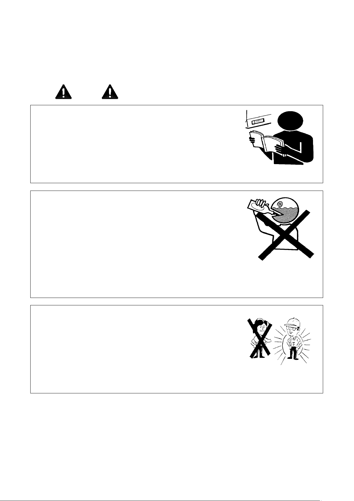
The driver should read through this manual and fully understand the
pregnant, color blindness or under 18 years, will be banned to operate this
The driver should have accepted special training and obtained license for
For new operator, always drive the machine at lower speed until he or she
1 Safety Precautions
1.1 General Provisions
Prior to implementation, you must read through and have a good understanding of user manual for safety
operation. Do not operate the machine at any time until you have mastered the operational steps indicated in this
manual. During operation, you should comply with the following precautions and important safety instructions
such as
Notices
1.
meaning as well as safety warning signs.
2. The driver should know how to operate and work with this machine.
Qualified operator
1. When operating this machine, the driver should have ability to judge in any
cases.
2. Those, who are in poor health, or have drunk, or lack enough sleep, or are
machine.
3.
driver subject to check-up process. He or she shall comply with the traffic
rules strictly.
Warning,
Attention, Important, Note.
Fig. 1-1 Read Notice
Fig. 1-2 Qualified Operator
4.
has been proficient in operation.
Uniform for drivers
1. During operation, the drivers should wear tight fitting clothes; No loose
working suits and shirts allowed, never put on neckties, scarves or
necklaces, etc; For female driver, long hair (if any) should be coiled up.
2. If you work on the site close to tractor or operating parts, coil up your hair
(if any), never put on neckties, scarves or necklaces, etc. If these items are
wringed into machine, this can cause serious injury.
3. During operations, it is necessary to wear protective tools such as safety
shoes, safety helmet, goggles and gloves.
Fig. 1-3 Uniform for drivers
1
Page 11
Safety Precautions
Keep machine clean without dirt, grease, or debris; When fuel and oil
The working fluid is dangerous and can cause serious injuries, such as high pressure hydraulic oil, brake
no smoking; Use a cloth to wipe up the oil
the manual. This can cause serious injury or even death; never install or disassemble the tires till you have
inflation pressure for tire is correct; the maximum inflation pressure cannot exceed specified
value. If this is the case, there will appear some crack threads on the edge of the tire, even such can cause
wasters can cause great threat to
proof container shall be used for disposed oil emission; never use
food and beverage containers to prevent others mistake swallow, resulting
n the ground, into subway or discharge them into
Don’t dispose arbitrarily used oil, fuel, refrigerant, brake fluid, filter
elements or batteries, which can be hazardous; more information for
way, contact local environmental
Application of fuel
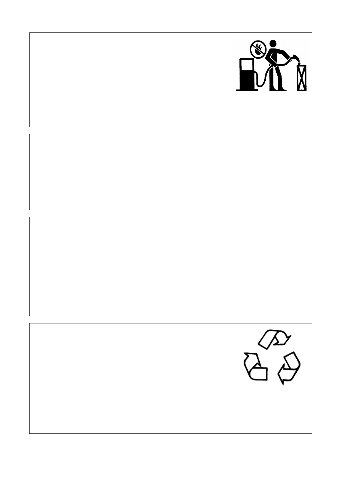
1. The fuel is flammable, and shall be refilled in the places far away from
Fire source.
2. Prior to refilling fuel tank, turn off the engine.
3. Don’t smoke and be close to fire when refilling and repairing fuel system.
4.
overflow, wipe them out with a clean cloth.
5. The quality of fuel and grease should meet the requirements as specified in
“Appendix” section.
Safety replacement of operating oil
1.
fluid, engine oil, etc.
2. Shut off the engine before replacing working fluid. No fire and
when it overflows.
Fig. 1-4 Application of fuel
3. Replace operating oil with those at specified grade.
4. The used operating oil is waste oil and can not be thrown away.
Tire maintenance precautions
1. In case of installation and removal of tire, it is easy to cause explosio n if you fail to operate as specified in
obtained proper and safety operation experience.
2. Make sure
explosion accident. When the inflation pressure has reached recommended value, deflation is required if both
sides of tire have not positioned yet. Inflate again after the tire is re-fixed and the edge is lubricated.
3. Regular check and tighten torques of locknuts and bolts on the front and rear wheel rims, in order to avoid
machine from rollover caused by disengagement of wheel during operation, and protect operator from
serious injury and eliminate excessive damage to the machine.
Disposed oil and waster placement
1. Improper disposal of used oil and
ecological environment.
2. Leak-
in accidental injury.
3. Don’t dump used oil o
other water sources.
Fig. 1-5 Waster placement
4.
reusing or disposing wasters in a right
protection department or recycle center.
2
Page 12
Safety Precautions
n’t use cinders, bricks (hollow) or other fragile substance under
d rear window. In the case of emergence, lift
Underway of living and industrial electricity cables
1. Make sure to secure all machine parts to prevent them loosening and electric shock.
2. When driving through under living and industrial electricity cables at low speed, make sure the maximum
height falls into the range of cable safety values as required to avoid electric shock caused by hooking or
touching with cables.
3. Prevent risk of electric shock from touch with high voltage wires during transportation, operation and in
shutoff state.
Correct support for tractor
1. To descent the parts or tools onto the ground, the tractor and its parts
needed to be lifted shall be supported safely.
2. Do
continued pressure to support machine.
3. Don’t operate tractor in the case only having a jack is used for support
tractor.
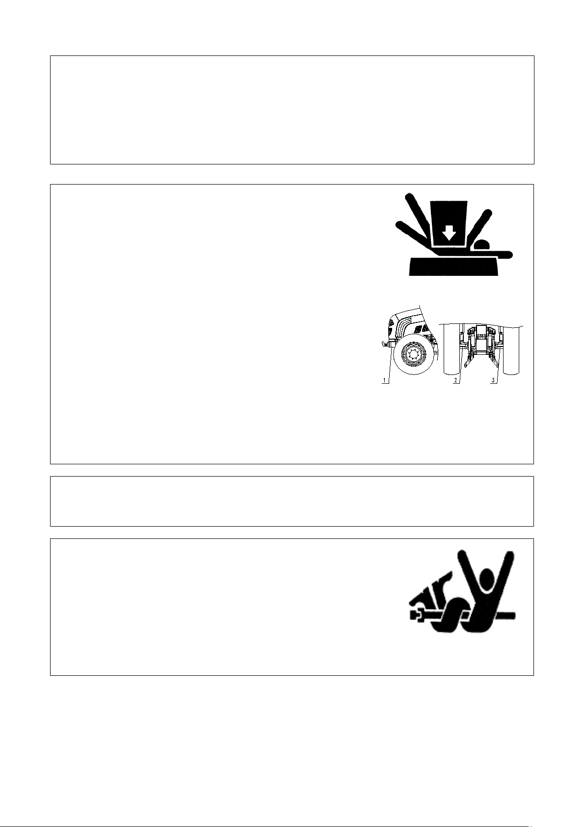
Fig. 1-6 Support risk
4. Before operating jack, you should read through the user manual
carefully. Never overloading, this is the case only if rigid support deck
is stalled to avoid injury and property losses.
5. When using jack, only use it for support right under left and right axle
shaft housing of rear axle and front bracket, no need to support other
parts.
Fig. 1-7 Jack support parts
1.Front bracket;
2.Left axle shaft shell;
3.Right axle shaft shell
Cab emergency exit
There are three emergence exits in the cab, left door, right door an
unlock handle to open the doors or rotate opening handle clockwise to open rear window and leave the cab safely.
Avoid touch with moving parts
1. When the machine is running, never carry out lubrication, maintenance,
service or adjustment operations until its shutdown.
2. Make hands, feet and clothes away from moving drive components.
3
Fig. 1-8 Avoid touch with
moving parts
Page 13
Safety Precautions
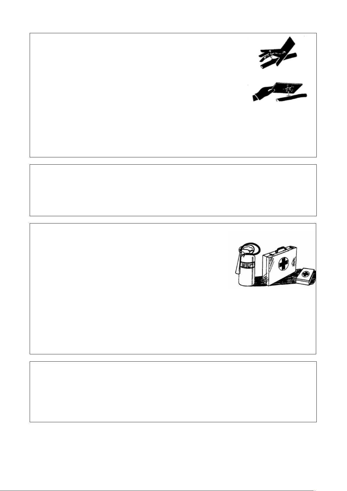
Fig. 1-10 Emergence treatment
s sufficient strength to penetrate and injure
body on the hand, ear or skin. To check, repair hydraulic line, the pressure
on hydraulic system shall be released. Afterwards check possible leakages
y from
In case of injury resulting from leaked hydraulic oil, immediately seek
medical advice. If failed to take necessary treatment promptly, this can
ng up near pressure liquid pipelines, it can produce a kind of spray
ine or around other inflammable
materials for heating. Thermal radiation other than flame may lead to
accidental pipeline damage.
s seat; in the case of a machine without a
When the machine starts or is working, anyone cannot be allowed to climb over the machine, and far away
from area where this machine is placed, in order to avoid injury.
d others, do not risk driving or operating the
machine. Only when making ensure that the machine is repaired by qualified technician and there is no one
When optional or replaced part is installed, the engine must be closed, stop the tractor on the safe place for
replacement. Prior to replacement, read through safety marks and user manual carfully, or carry out
When the tractor is connected to other devices, if lack working experience, it is possible to cause injury, or
Hydraulic pineline Caution
1. High-pressure hydraulic oil ha
by using paperboard or wood board, thus avoid hands and bod
injury resulting from high-pressure liquid.
2.
cause serious infection and unwell reaction.
Fig. 1-9 Hydraulic line Leakage
3. If heati
mist, which can in turn cause severe burns on your body or others. Do not
heat up by pipelines.
It is not allowed to u se electr ic wel ding, gas weld ing
or welding torque at hydraulic pipel
Taking a ride for others
1. Only driver can be allowed to operate the machine in driver’
co-driver’s seat, other personnel are not allowed to get on. When there is a co-driver’s on a machine, it can be
applied to another one who is prohibited to cause interference, influence and obstacle to the driver.
2.
Emergency treatment
1. When the brake is failed, stabilize the steering wheel, and drive to a
safe place, then immediately turn off the engine.
2. When the steering wheel is failed, immediately depress brake pedal
and then turn off the engine.
3. A first aid kit shall be prepared at hand. There are telephone numbers
of emergence center, hospital and fire department written down
everywhere near all telephone sets. In the case of incidents, call local
emergency center, hospital or fire department immediately for help.
4. In order to guarantee the safety and security of your own an
around service site, the operator can restart the machine to drive at low speed.
5. In the case of fire, immediately shut off engine. If there is fire extinguisher available, it is necessary to use it
spray on flame base; If no fire extinguisher is available, use sand or others materials to put out the fire.
When tractor connects to other operating devices or parts are replaced
1.
replacemenet by professionals if necessary.
2.
ask the professional for help when necessary.
4
Page 14
Safety Precautions
ry may run the risk of
explosion, the battery shall be far away from open flame
), then remove the
battery. To install battery, the first step is to install the
After the charging is over, disconnect power supply, and
detach cable from battery post to prevent battery explosion
Do not use the batteries out of those specified for the
Avoid breathing smoke generated by respiratory
If the roll bar becomes slack or is removed for any reason, it is required to reinstall the remaining parts in a right
+ pole
Proper application of battery
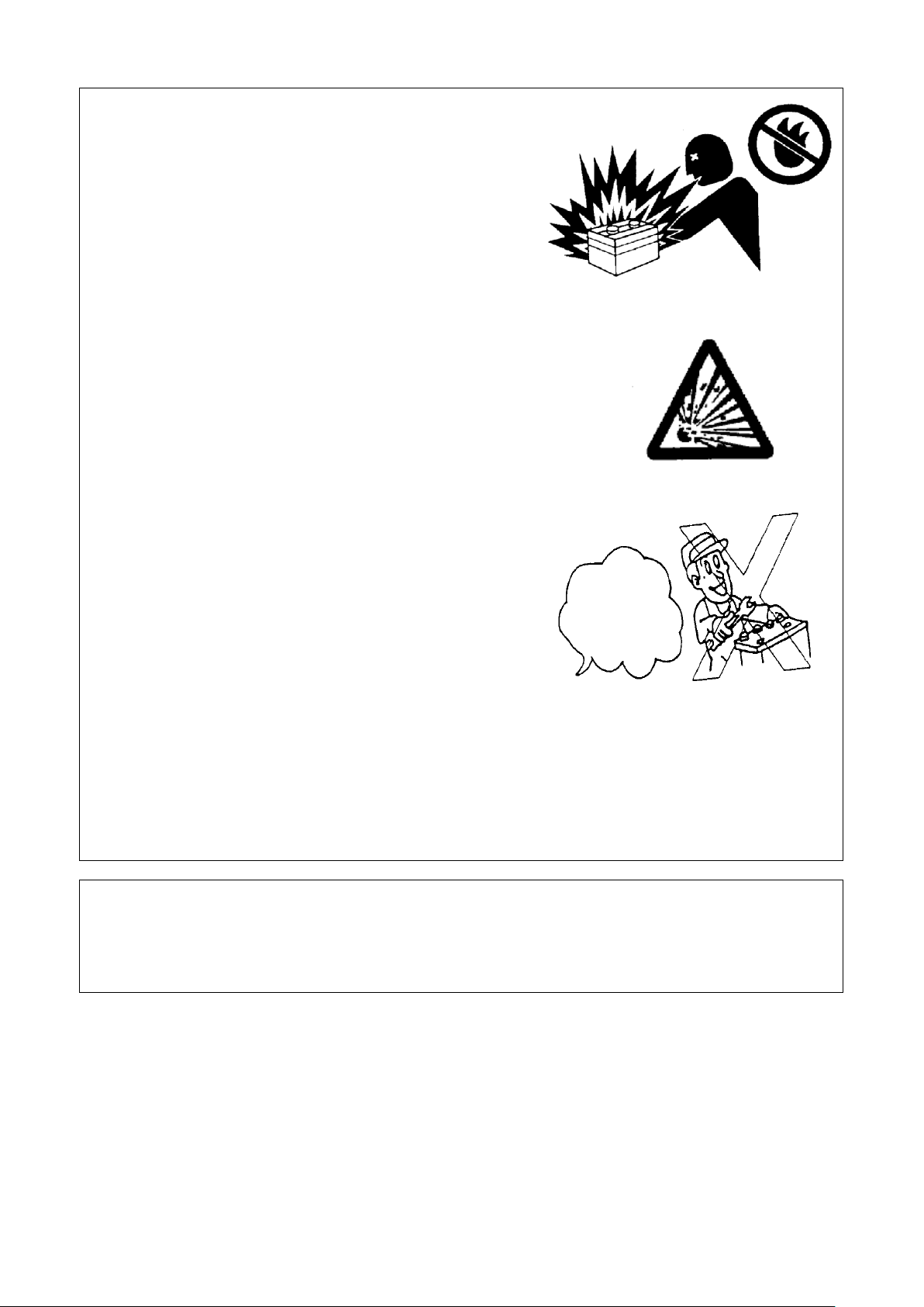
1. As the gas overflowed from batte
(such as matchsticks, lighters or cigarettes etc.); avoid short
circuit, sparks.
2. The battery is only used for starting engine, not for any other
purpose.
3. When the battery is charged or replaced, you should read the
caution labels on the battery carefully.
4. Remove bond strap on negative pole (-
positive pole (+) cable.
5. Before the battery is charged, remove it from machine.
6. P rior to charging, check if battery end cap vent is smooth and
the ambient is ventilated.
7. P roper charging current depends on rated capacity of battery.
caused by possible electric ignition.
8.
machine.
9. It is more dangerous to touch with electrolyte (dilute Sulfuric
acid). If it touches with eyes, skin and clothes, immediatel y
wash them away with clean water; If it is splashed into eyes,
flush it fully with clean water, then seek medical treatment.
To avoid injuries, the following actions shall be taken:
① Wear goggles and rubber gloves;
Fig. 1-11 Application of battery
Fig. 1-12 Electrolyte danger
– pole Start
Fig. 1-13 Check of battery
②
electrolyte;
③ Prevent electrolyte splash or drip;
④ Use correct and parallel startup process.
Keep roll bar installation correct
way. Tighten set bolts to right torque. If the roll bar structure is damaged, such as rollover accident, distortion etc.,
protective function may be lessened. The damaged roll bar must be replaced with a new one.
5
Page 15
Safety Precautions
ly expansion or in lockup positions. If tractor is operating with roll
bar to fully expansion position and fasten it
ular check safety belt and assembly fasteners to see whether those fasteners are slack, or safety belt is
For safety and security of your life and property, operate the machine in a secure way to bring happiness to
between tractor and agriculture implement or trailer, press whistle for warning others to prevent accident
lever is changed to neutral position, power output control stick and front drive joystick disengaged, control
hort circuit terminal start engine. Otherwise, when the gearbox shifts to the gear, the
smoothly. Never place some obstacles between floor and pedal. Do not place items which can be rolling or
sliding down when stepping down the pedal. No carpets or other matting materials around pedal to avoid
Prohibit anyone to get on or off tractor while the tractor is driving, or crawl under the tractor body for
gear lever to neutral position and lock up the
full attention to whether it is beyond the height limit or not when driving through culverts and bridges. Slow
uring uphill or downhill, change to the lowest gear, and use throttle control reasonably. The tractor is
inhibited to engage neutral gear or depress clutch pedal to slide down hill. No change of gear allowed when
When driving on the road, you should pay attention to traffic marks, and strictly follow the traffic rules, in
When driving, you should strictly follow the traffic rules. The space between two vehicles shall be
dam is more unsecured, the weight of tractor may make it collapse.
Proper use of folded roll bar and safety belt
1. If tractor has folded roll bar, keep it in ful
bar in folded position, be careful of driving tractor. If the roll bar is in folded position, do not use seat belt.
2. If the tractor restores to normal operating conditions, lift roll
immediately. When roll bar is in fully expansion or lockup position, the safety belt must be used.
3. If spare fastener, retaining ring or retractor is available, the safety belt must be replaced on the whole.
4. Reg
damaged or not, such as incision, scratch, abnormal damage and wear etc.
5. If there is no any roll bar or cab on the tractor, do not use safety belt..
Warning!
1.
your relative.
2. When the tractor startup, you should note whether there is obstacle on the road or not and if someone stands
injury due to suddenly startup of the tractor.
3. Do not start and operate tractor at the places away from driver ’s seat. When starting tractor, make sure gear
stick for lifter in neutral position, in order to prevent accident caused by suddenly startup of tractor.
4. Do not use jumper s
tractor will automatically drive out of control. This can cause the accident hazards.
5. The movement of all the pedals shall not be hindered. All the pedals can restore to the original places
accident due to pedal movement.
6.
overhaul when engine is in operation, as this can cause personal injury.
7. After stopping, the driver shall pull out the key, move the
parking brake handle before he or she gets off the tractor, in order to prevent accident due to auto-movement
out of control.
8. During transportation, left and right brake pedals shall be interlocked together, control appropriate speed. Pay
down the speed in advance when turning around to avoid unexpected accident, such as rollover, collision.
9. D
uphill or downhill to avoid rollover risk.
10. Do not take sharp turn when driving at higher speed or use unilateral brake to take sharp turn, in order t o
prevent rollover risk.
11.
order to mitigate the risk of accidents.
12.
maintained no less than 60m to mitigate the risk of accident collision.
13. As the embankment near ditch, cave and
Make a detour, or this can run the risk of accidents.
6
Page 16

Safety Precautions
14. The tractor shall never be overloaded, and is prohibited to work at the extreme limit in order to avoid
vest or yard field, it is required to install spark quench on exhaust pipe to
In the case of power output operation, it is a must to make sure reliable connection and protection to prevent
risk due to their separation from tractor. While disconnecting or towing implement, make sure all axle pines
On charging battery, it is necessary to make sure smooth filler plug vent, far away from open flames. Turn off
Keep safety height consistent with the value allowed for high voltage output lines to avoid unexpected
When tractor is working at field harvest, threshing or transportation for flammable goods, the fire
On transportation of tractor, the user should install fault warning sign plate. If tractor fails to operation and
the position of more than 30m from aft
tractor, which is used for remain other drivers that there is a vehicle to be repaired on the road ahead so as to
When tractor PTO shaft is working, the housing must be installed for PTO shaft. It is prohibited for
e tractor shall not take a sharp turn to prevent
universal joint or PTO shaft from damage; when PTO shaft is unused, the handle shall be separated from it to
off of the engine in order to prevent
When the tractor has to be stopped on the slope, the hand brake stick shall be in the position for operation,
e gear (forward gear in uphill position and reverse gear in downhill position).
Be sure of using parking brake and chocking up rear wheel with triangular plug block to prevent unexpected
and adjustment shall be performed by qualified and experienced professionals with
Before installation of optional parts, new parts or articulated implements, you shall read through instruction
personal injury or damage due to overload.
15. When the tractor is workin g at night, it is essential to set up a good lighting equipment in order to alleviate
influence on performance of tractor and avoid the occurrence of dangerous accident.
16. When the tractor is working on har
mitigate the risk of unexpected accident.
17. In the case of rain or snow weather, slow down operating speed in order to alleviate the risk of rollover event
due to slippery ground.
18.
injury caused by separation of moving parts.
19. When linkage or traction of implement, all axle pins shall be connected in a secure way to alleviate collision
separate from tractor to avoid personal injury or machine damage due to unclear separation.
20. When lifting up, pay attention to engine throttle control in order to avoid injury or machine damage due to
overtop.
21.
the power before the battery is fully charged to prevent explosion.
22.
accident!
23.
extinguisher shall be equipped on the tractor to prevent the occurrence of accident.
24.
needs repairing service, the fault warning sign plate shall be put in
avoid accidents.
Notice:
1. Regular check all bolts, nuts and loose parts on front and rear drive wheels and steering tie rod, if loosening,
tighten them in time to prevent unexpected accidents.
2.
personnel to close to PTO shaft. When it bears load, th
avoid unexpected accident.
3. After stopping, the driver shall not leave the tractor prior to shut
unexpected accident caused by suddenly startup of tractor out of control.
4.
shut off engine, and engage th
accident due to self movement out of control.
5. Tire installation
appropriate special tools. Improper installation of tire can cause severe accidents.
6. On cleaning up water tank, turn off the engine, and then start to work until the water tank cools down. This
can prevent scalding injury and damage to the tank.
7.
for safety mark and the user manual carefully.
7
Page 17
Safety Precautions
factory or overhauled tractor shall be grinded as required of tractor specification so that the normal
for least 48h and lubricating oil for power train has filtered by oil filter whose precision is consistent with
Prior to startup of tractor, be sure of check oil line, circuit and the cooling water; after startup, observe the
itness between tractor and
driven implement is reasonable. In the case of plough, the angle between PTO shaft and universal joint is less
than 15°; with normal hydraulic control, the angle between PTO shaft or implement input shaft and drive
into soil till the power output is connected as this can cause severe damage to rotary tiller and clutch of
ncy, power source shall not be cut off when steering. However,
in winter, you must use antifreeze liquid in order to
The front drive axle of tractor is only used in agriculture field work and when the road is muddy to prevent
In the process of driving tractor, the driver is not allowed to step on brake pedal or clutch pedal, in order to
link of suspension
device to shortest status, and regular limited rod to prevent implement swing from side to side. While
tightening locknuts on the top link and limited rod to ensure driving safety and alleviate the risk of machines
If the implement articulated to the tract displaces, lock it up tightly; Descend the implement onto the ground
ect eligible parts and components in order to ensure the normal
radiator cap. After
Important:
1. New exlifecycle of tractor can be guaranteed.
2. The tractor shall be required to use various solutions. Only if the fuel has finished sedimentation for impurity
lifter suction filter, can filling work be carried out. This can guarantee the life of related parts and working
effectiveness of tractor.
3.
reads of all meters and normal operation of tractor.
4. Before the agriculture implement will be driven by using PTO shaft, check if f
shaft is not greater than 20°after implement is lifted for steering on the edges of field; Never take rotary tiller
tractor [in order to improve operation efficie
the lifting height of implement from ground shall be 200mm or so].
5. When the temperature drops to the degree below 0℃
prevent damage of major parts such as water tank and engine.
6.
the tire skid; In other cases, it is disabled, or it is easy to cause early wearing for tires and drive train.
7.
mitigate early wearing of brake or clutch.
8. The tractor equipped with agriculture implement moves forward on the road, adjust top
and implement damage.
9.
before the driver leave tractor in order to mitigate the risk of machine and implement damage.
10. During maintenance, it is essential to sel
service life of tractor.
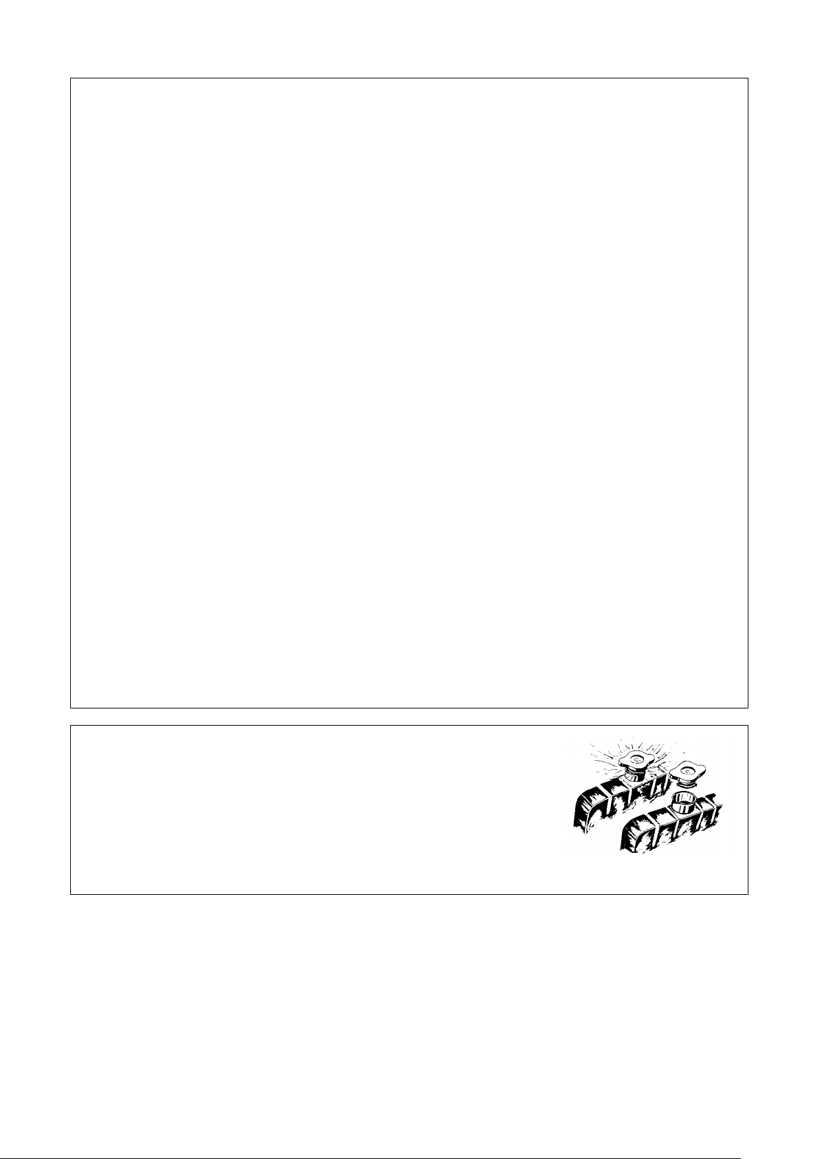
Unscrew radiator cap
When the engine is still hot, be careful of unscrew the
Operating for several minutes, deactivate the engine, and then loose radiator
cap to the first gear. Afterwards unscrew the cap until the pressure is released.
Fig. 1-14 Unscrew radiator cap
8
Page 18
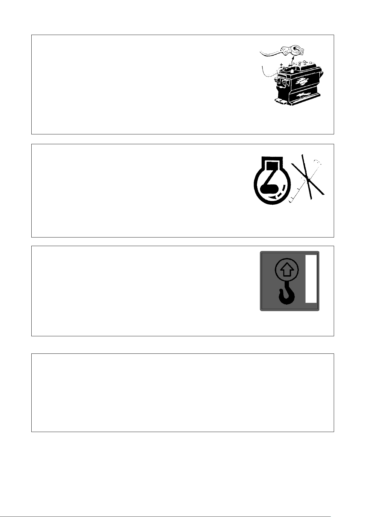
Safety Precautions
y before electrical appliance
When repairing tractor by electric welding, it is necessary to disconnect
ground wire from battery and unplug large connector from engine,
Do not allow tractor to work with “sick”, particularly in the cases of free
During lubricating maintenance and field adjustment, deactivate the
Hoist the tractor
Hoisting position
When repairing electric parts
1.
Pull out the key for the electric lock s witch.
2. Cut off the main power switch for the batter
maintenance.
3.
hydraulic part computer controller (if equipped), or it is easy to cause
damage of battery, controller and instrument cluster.
In the case of tractor abnormities
1.
or super-low oil pressure, overtop water temperature or unusual noise and
odor, immediately stop for check and troubleshoot problems.
2.
engine.
Allowed hoisting position in the front;
Fig. 1-15 Repair of electric
parts
Fig. 1-16 In the case of tractor
abnormities
Safety rules when the tractor is unattended
1. Shift to neutral gear and place hydraulic control stick to neutral position.
2. Descend lifter or tow articulated device onto the lowest position.
3. Engage parking brake.
4. Remove engine ignition key from dashboard.
5. Choke up rear wheel with triangular plug block if stopping on the slope.
Fig. 1-17 Hoisting symbol of
tractor
9
Page 19
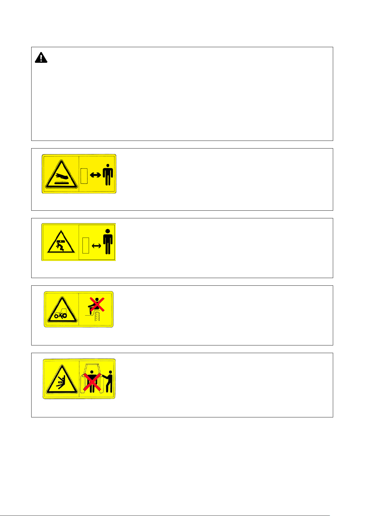
Safety Precautions
visible. If there is dirt, flush them out with soap water, and wipe up
If the safety mark is missing or unclear, timely contact the dealer or manufacturer to reapply for register or
Meaning: when operating, you need to keep a certain space with tractor to
Meaning: When lifter lever control mechanism is operating, move into areas
1.2 Safety warning signs
Notice:
1. Keep the safety warning sign clear and
with soft cloth.
2.
replace.
3. To replace the part labeled with safety warning sign, the used part needs to be replaced with safety warning
sign.
4. The terms prompted in safety warning sign refers to personal safety, and must be strictly enforced.
Meaning: when operating, you need to keep a certain space with hot surface
of machine to prevent injury.
Paste location: outside of muffler and tank side.
Fig. 1-17 Safety warning ID IV
Fig. 1-18 Safety warning sign II
Fig. 1-19 Safety warning sign VI
prevent injury.
Paste position: Rear end of mudguard
Meaning: It is not allowed to be seated at the places other than seats to
prevent shading driver’s sight and causing injury.
Paste location: On the front side of left and right mudguard.
far away top link lifting area.
Paste position: Rear end of mudguard
Fig. 1-20 Safety warning sign III
10
Page 20
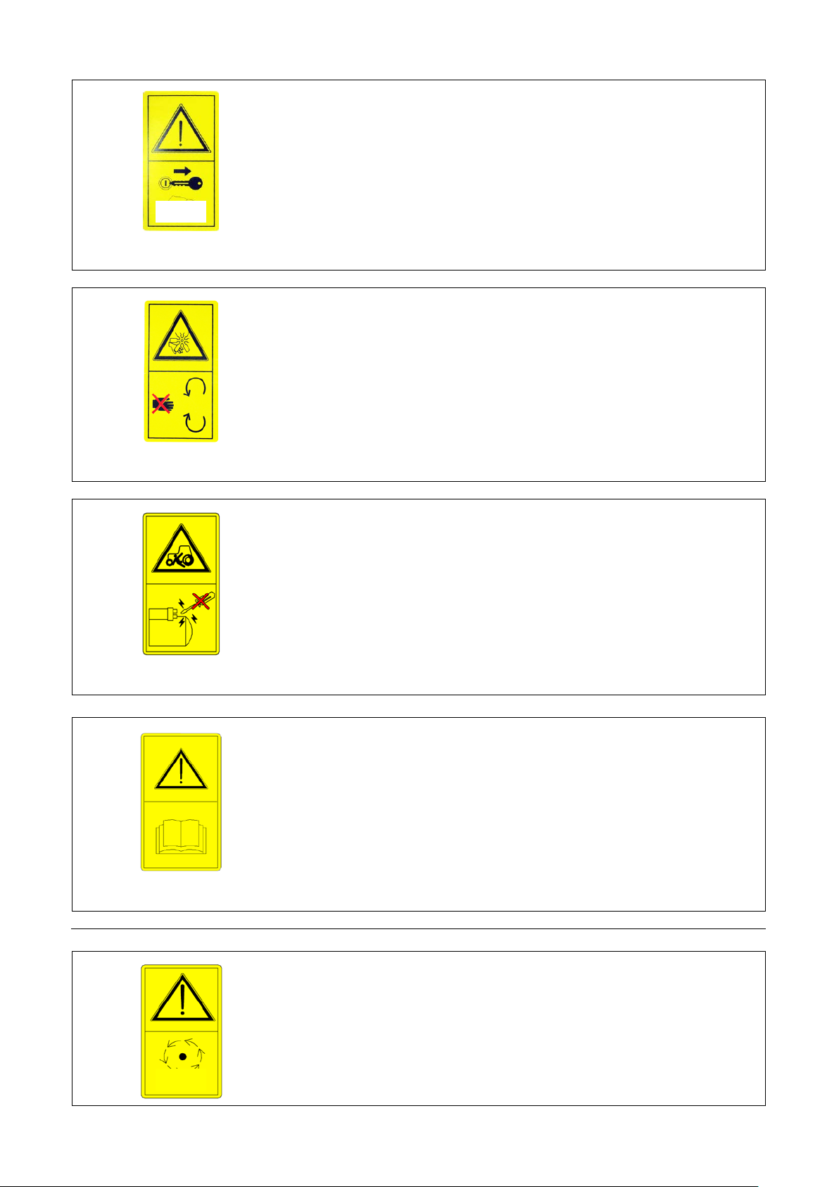
Meaning: Prior to repair, maintenance, adjustment, shut off the engine, and
When the engine is operating, never open or dismount safety
protective cover, and Keep hands outside working site in order to prevent
start engine on the driver’s seat. Disable startup of
Meaning: To prevent injury, touch with it only if all the parts of machine
S
Fig. 1-21 Safety warning sign I
Safety Precautions
pull out startup key. Operate as specified in the manual to prevent injury.
Paste location: front side of instrument desk.
Meaning:
injury.
Paste location: on the protective cover of engine.
Fig. 1-22 Safety warning sign IX
Fig. 1-23 Safety startup mark
Meaning: The driver shall
engine By short-circuit on the starter side in order to prevent injury;
Paste location: on the front side of instrument desk.
Meaning: To prevent injury, read through the user manual to understand the
meaning of safety marks without Text description.
Paste location: on the front side of instrument desk.
Fig. 1-24 Read manual mark
completely stopped;
Paste location: On PTO (power take-off shaft) g protective cover.
top
11
Page 21
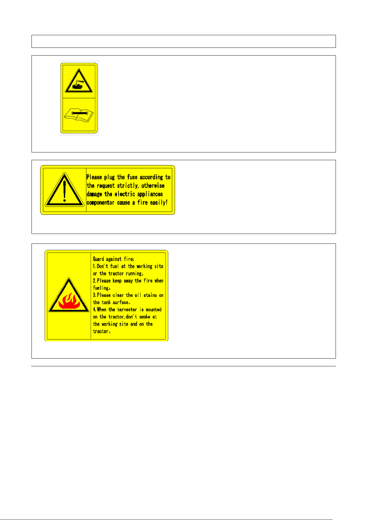
Fig. 1-25 PTO safety mark
Meaning: During maintenance of battery, look up the user manual to
Fig. 1-26 Battery mark
Safety Precautions
understand appropriate Specification for maintenance so as to prevent injury.
Paste location: on the upper surface of battery.
Meaning: refer to Fig. 1-27.
Paste location: near electric box.
Fig. 1-27 Fuse safety warning sign
Meaning: refer to Fig. 1-28.
Paste location: near oil port on the fuel tank
Fig. 1-28 Refueling fire proof mark
12
Page 22
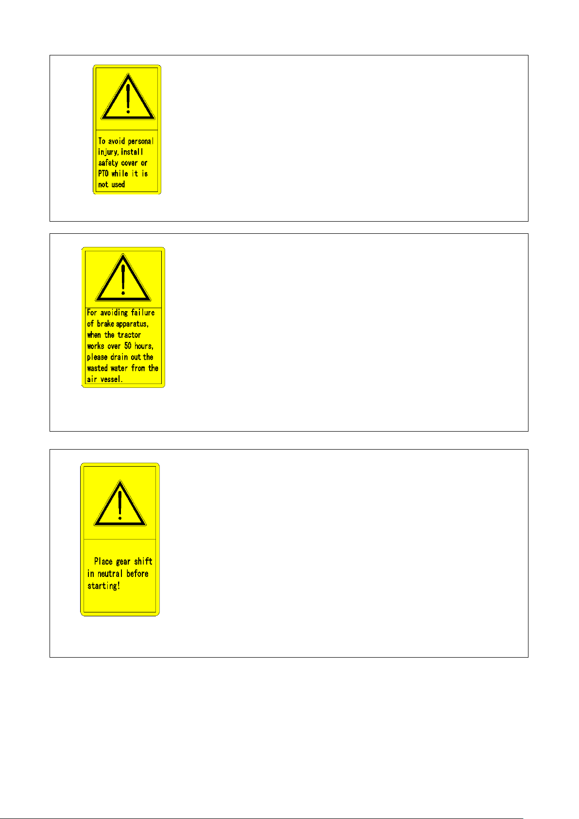
Fig. 1-29 PTO safety mark
Safety Precautions
Meaning: refer to Fig. 1-29.
Paste location: near PTO shaft.
Meaning: refer to Fig. 1-30.
Paste location: on the surface of gas tank.
Fig. 1-30 Air braking warning
sign
Fig. 1-31 Safety startup
warning sign
Meaning: refer to Fig. 1-31.
Paste location:
Front side of the instrument desk
13
Page 23
Safety Precautions
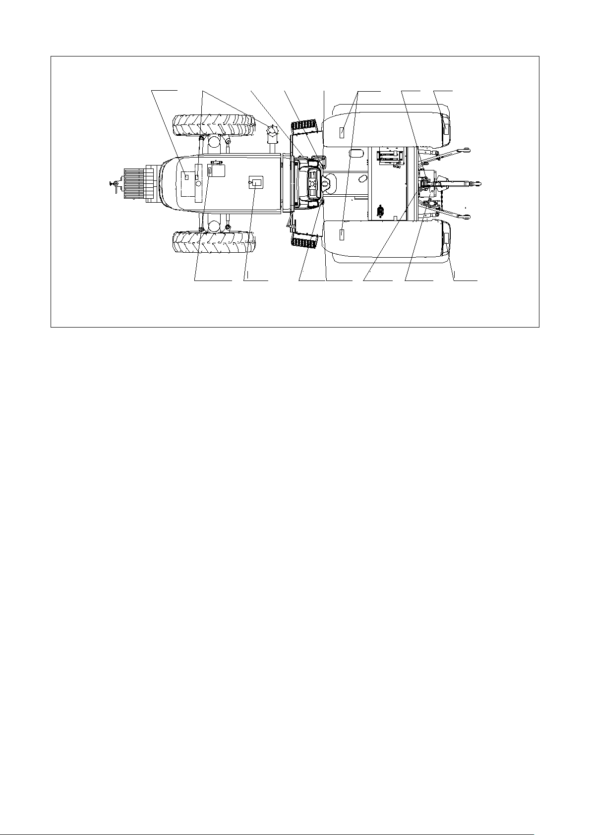
Fig.1-26
Fig.1-17
Fig.1-27
Fig.1-23
Fig.1-21
Fig.1-19
Fig.1-25
Fig.1-18
Fig.1-22
Fig.1-28
Fig.1-24
Fig.1-31
Fig.1-30
Fig.1-29
Fig.1-20
Fig. 1-32
Schematic diagram fo r warning sign pasting
14
Page 24
Product Identification
he product nameplate of engine is an important mark used for
he engine nameplate is
hen the tractor runs in service, the
When the tractor is shipped out of factory, machine model and
2 Product Identification
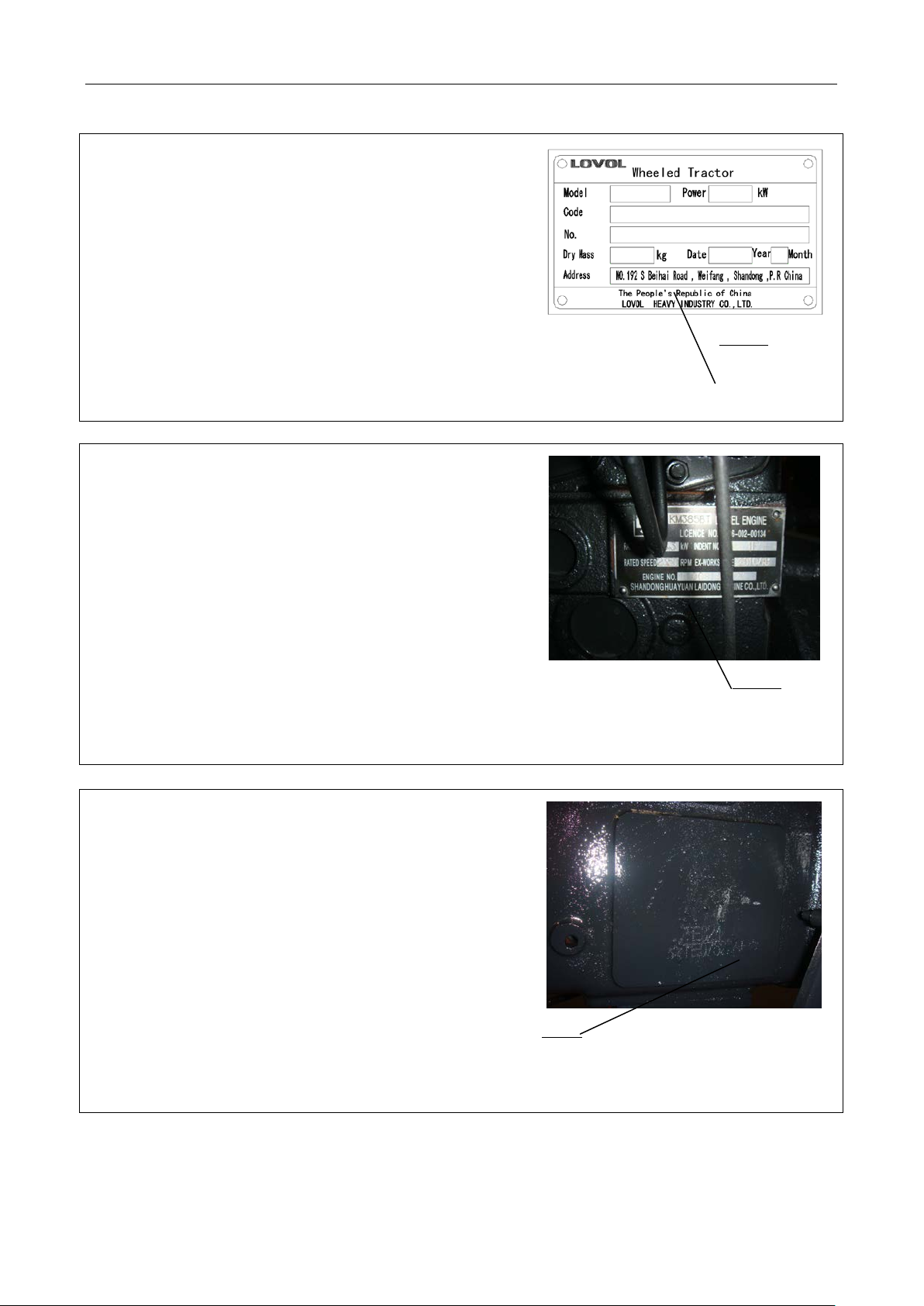
Product nameplate
The product nameplate is an important mark used for effective
identification. It is located on the left sid e of instrument desk in
the cab of tractor. When the tractor runs in service, the
responsible person will check this nameplate. Do not lose
product nameplate, and keep it clear.
Engine information
T
effective identification of tractor power supporting device. It is
located under tractor guard hook. T
equipped on the engine. W
responsible person will check this nameplate. Do not lose product
nameplate, and keep it clear.
1
Fig. 2-1 Product nameplate
1. Product nameplate
Fig. 2-2 Engine nameplate
1. Engine nameplate
1
Machine model and manufacturing number
ex-factory manufacturing number is marked on the left side of
transmission gear housing, as shown in right Fig. 2-3.
1
Fig. 2-3 Manufacturing number
1. Manufacturing number
15
Page 25
Operation Instruction
Operate the tractor properly to fully play its performance, reducing tractor wears and
3 Operation Instruction
Attention:
accidents as well as guaranteeing the completion of high-quality, high-efficienc y, low-consumption and safe field
and road operations of the operator.
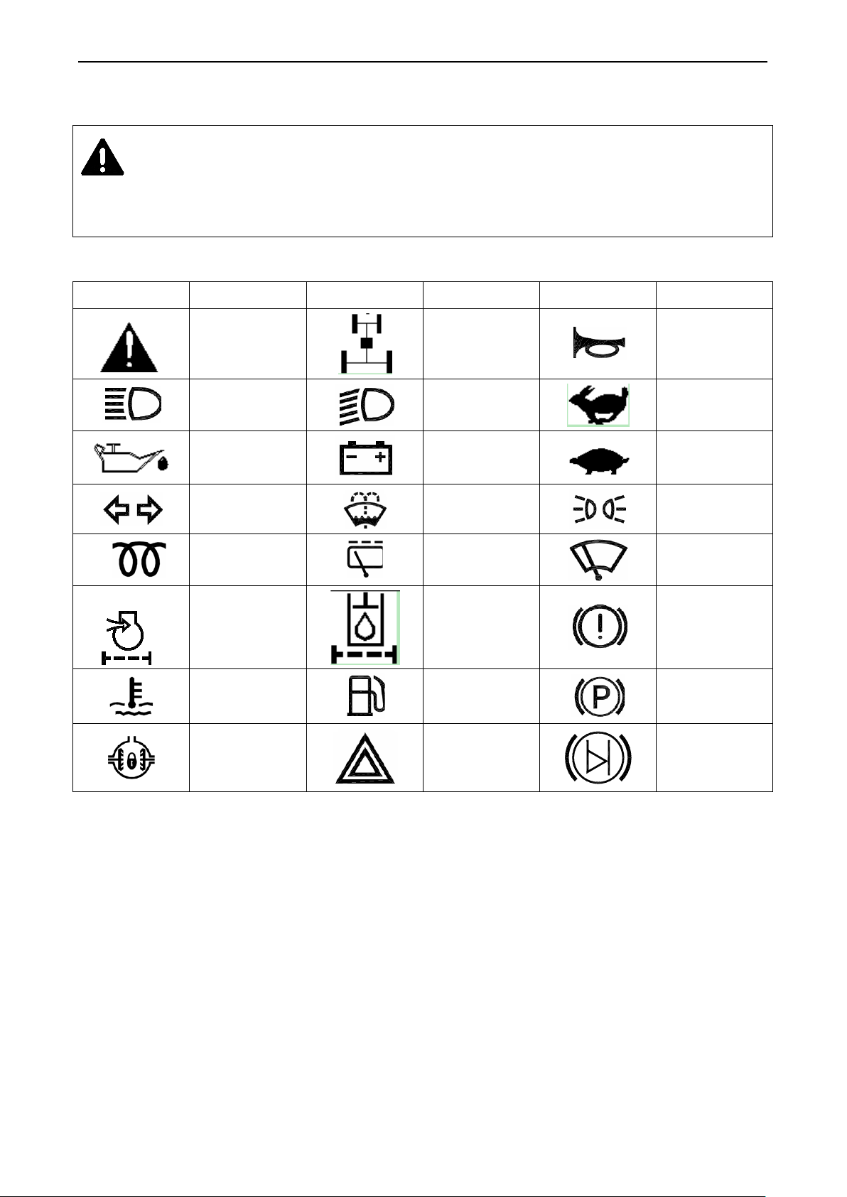
Table 3-1 Common marks and symbols
Symbol Implication Symbol Implication Symbol Implication
Safety warning
sign
Four-wheel
drive
Horn
High beam
Oil pressure
Direction lamp
Battery charging
Low beam
condition
Washer
Fast
Slow
Position lamp
Engine
preheating
Air filter
blockage
warning
Engine coolant
temperature
Rear wiper
Hydraulic oil
filter
Fuel volume
Wiper
Air brake
failure/fault
Parking brake
Differential lock
Hazard warning
Brake fluid
warning
16
Page 26
Operation Instruction
scale agriculture tractor, featured with compact
3.1 Product description
This manual describes usage, technical maintenance, adjustment, fault and troubleshooting and so on for LOVOL
series wheeled tractors.
LOVOL series wheeled tractor is of multi-purpose mediumstructure, handy operation, flexible steering, large towing force, and convenient maintenance etc.
3.2 Tractor maneuvering mechanism and instrument
3.2.1 Tractor maneuvering mechanism
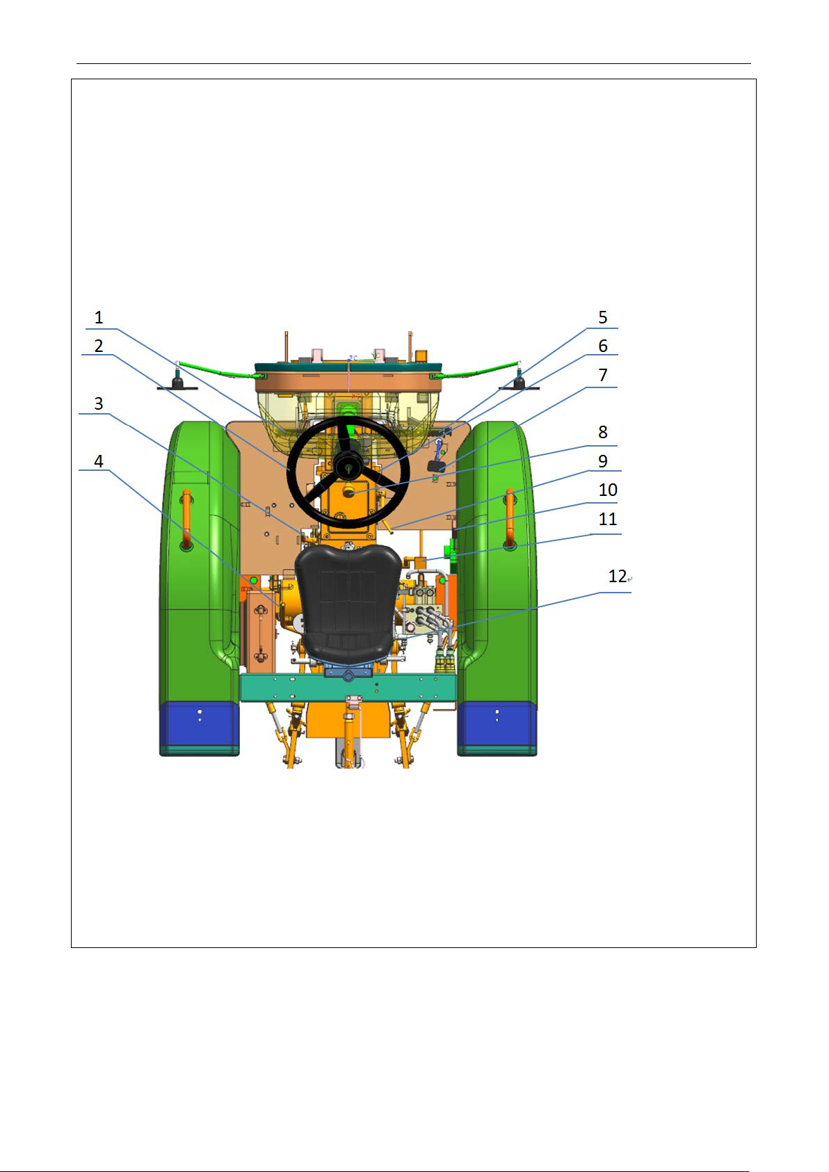
Fig.3-1 Tractor maneuvering mechanism
1.Clutch Pedal 2. Steering wheel 3.Front drive axle joystick 4. Power takeoff gear shift lever 5.Brake
pedal 6. Parking brake lever 7. Foot accelerator pedal 8. Main gear lever 9. Auxiliary gear lever 10. Manual
accelerator joystick 11. Differential lock joystick 12. Distributor joystick
3.2.2 Combination instrument and switch
17
Page 27
Combination instrument
ng, the driver should take note all kinds of instruments and indicators. If
Right tu rn signal
Operation Instruction
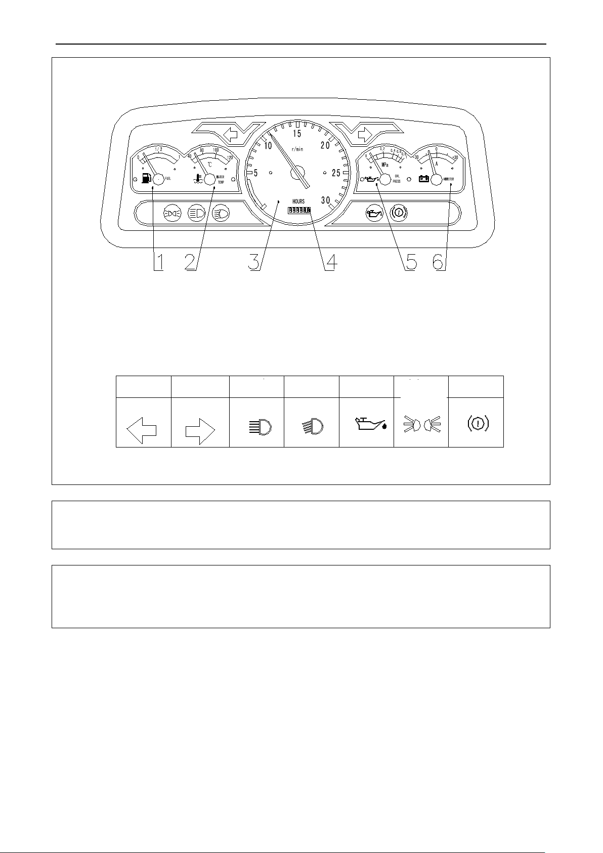
Fig.3-2 Combination instrument
1. Fuel gauge 2. Water temperature gauge 3. Tachometer 4. Timer 5. Oil pressure gauge 6.Ammeter
Warning Indicator System Table for Combination Instrument
Left turn signal
High beam
Fig.3-2 Combination instrument
Important: During tractor worki
abnormal, please immediately park and repair.
Left side rocker switch combination
Low bea m
Oil pressure indicator
Small lamp
Air brake
18
Page 28
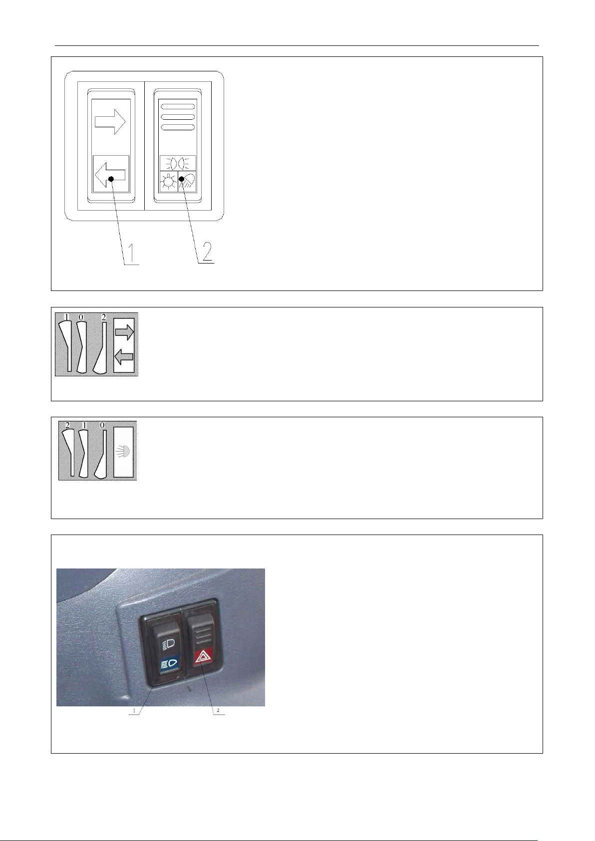
left turn signal lamp; Position “0”: power off; Position “2”:
Fig.3-3 Left side rocker switch combination
Turn signal switch
Operation Instruction
1 Switch for direction lamp;
2 Switch for work lamp
Position “1”: switch on the
switch on the right turn signal lamp.
Fig.3-4 Turn signal switch
Switch for work lamp
“0”: Power off ; “1”: Position lamp on ; “2”: position lamp and backup lamp on
Fig. 3-5 Switch for work lamp
Right side rocker switch combination
Fig.3-6 Right side rocker switch combination
1 Dimmer switch;
2 Hazard warning switch;
19
Page 29
Dimmer switch
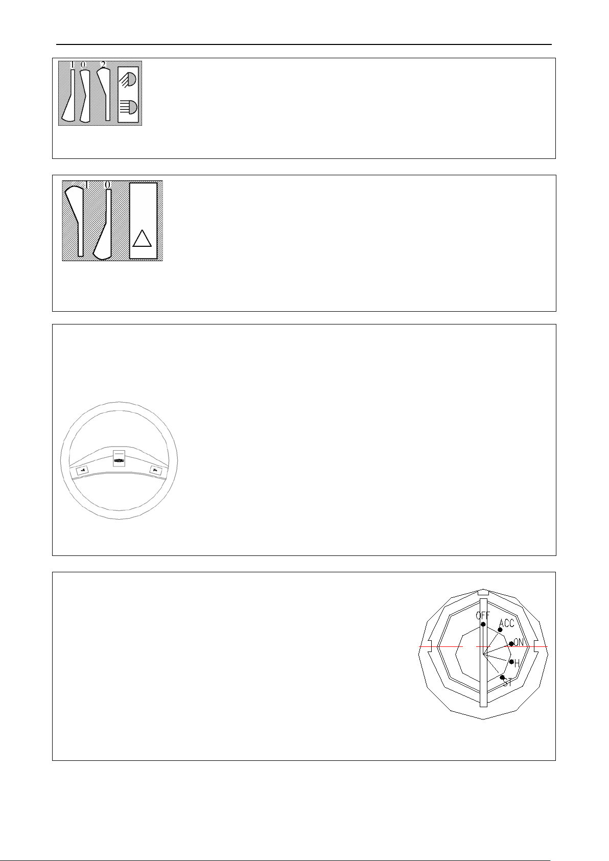
Position “1”: turn signal lamps in front and rear and at left and right, left and right turn
signal indicator lamps on the instrument and indicator lamp on the hazard warning
by in front and behind via
Clockwise rotate the preheat start knob to ACC to turn on the auxiliary
After preheating,
Position “2”: high beams light up; Position “0”: low beams light up; Position “1”: standby.
Fig.3-7 Dimmer switch
Hazard warning switch
switch all light up. When the tractor is parking on a highroad due to faults or other
causes and it is necessary to warn vehicles and passers-
activating this function in order to avoid accidents.
Fig.3-8 Hazard warning switch
Operation Instruction
Horn switch
Horn switch is located at the center of steering wheel. The horn switch could be turned on by pressing it, as shown
in following picture.
Fig.3-9 Horn switch
Ignition lock
electrical appliance. Clockwise rotate it to ON to turn on the control circuit.
Clockwise rotate it to H to turn on the preheating device.
rotate it to ST to start engin e. After engine is started , immediatel y loo sen it, th e
key will automatically return to ON. The time of key staying at ST should not
more than5s to avoid engine burnout.
3.3 Engine start
20
Fig.3-10 Ignition lock
Page 30
Operation Instruction
Prior to operations, please check the tractor carefully and comprehensively to eliminate hidden
Check the gearbox control lever and PTO control handle. Position the main gear lever, power output control
handle, front drive axle control handle respectively to neutral gear position. Position the distributor control
Pull the flameout cable locking device for flameout cable return. At the moment, the injection pump is
efore starting, please vacuum oil (fuel) pipe to
ensure diesel engine smooth starting. The method is as follows: loosen the air bleeding screw on the diesel
Then tighten the bleed screw on the diesel filter, loosen the bleed screw on the fuel injection
on water tank grille to prevent the engine from faults caused by poor heat
Since heat dissipation condition is poor during field operations, when the tractor is equipped with a packsack
picture). Otherwise, the started engine will reversely start the starter, and therefore
Warning:
dangers for effective prevention of accidents.
3.3.1 Preparations for engine start
Before starting, please carefully check each part for tight and reliable
connection, each control mechanism for normal work, pipe joint for
tightness and there should not be any leak of oil, water and air.
Check the lubricant level in the engine oil sump, gearbox, rear axle and
hydraulic system. The radiator should be filled up with cooling water
and fuel tank should be filled up with fuel.
The handle of fuel tank pipeline switch should be paralleled to oil pipe
to open the fuel pipeline.
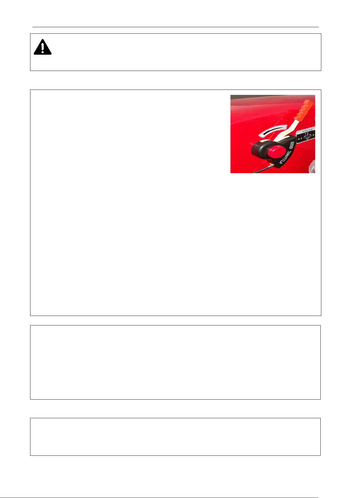
Figure 3-11 Hand throttle
handle to lowering position.
locating at oil supply position.
Hand throttle is set as semi-open state.
As to the new, overhauled or long-period stored tractor, b
filter, use hand pump to vacuum fuel pipe from the fuel tank to diesel filter until there is no bubble emerged
in bled fuel.
pump. Use the similar method to drain air until there is no bubble emerged in drained fuel.
Important:
1. Remove foreign matters
dissipation;
2.
harvester, it is recommend ed to install an auxiliary radiator at a proper position as to guarantee long-term
continuous engine operation.
3.3.2 Start the engine
Important:
ON (see ignition key
1. Af ter engine is started, please immediatel y let your hand goes to allow the key automatically return back to
21
Page 31

Operation Instruction
Starting time should not be more than 5s each time and starting interval should not be less than 15s each
again to “ST” to start engine. After engine is started, please immediately let your hand go, the key will
℃
. Then refill into oil sump. Never heat the oil sump.
In the case of tow start the tractor, once the engine operates, depress the main clutch pedal immediately and
ine starting, please immediately decrease the throttle openness to allow the engine at idle speed. At
and load, especially to justly started engine. Do not run at high
ng, the oil pressure gauge pointer should not point to red range at left side at any
damaging it.
2.
time. To maintain the battery charging performance, continuous times of starting engine should not exceed 3
ones. If failure after successively 3 times, please find out the cause and start again.
3.3.2.1 Battery starting
Ambient starting (over -5 ℃): Turn the ignition key clockwise to “ON” to turn on the circuit. Then rotate it
automatically return back to “ON”. As tractor has safety starting switch, f irstl y depres s do wn the main clutch
pedal, then rotate the key to start engine.
Pre-heat starting (only limited to tractor type with pre-heat circuit)
Use the pre-heat to start the engine at lower temperature (below -5 ℃), as the cold start is difficult. Place the hand
throttle to full position. R otate the starting switc h clockwise to Pre heat for hold it for (15~20) s and then to ST to
start engine. After engine is started, the key will automatically return back. At last place the h andle throttle to
small-openness position.
As to the tractor without pre-heat circuit, befo re starting engin e in severely cold winter, fill the radiator with over
90
Drain the oil in the oil sump (it is best to drain it when still hot) into a container with cap to be heated to
(70~90) ℃
3.3.2.2 Starting engine by towing tractor: when towing tractor, please engage high III-gear or high IV-gear.
To ensure safety, the speed of towed tractor should not be more than 15km/h.
Note:
reduce throttle opening.
3.3.3 Engine running
After eng
this time, check the engine oil pressure and ensure the oil pressure gauge pointer is pointing to green range.
After startup, the engine should not run at full-load immediately. It is correct to let the engine to be heated at
middle speed and with no load. Do not increase to max. speed or put it into full-load work until the coolant
temperature is up to 60 ℃ or more.
Slowly increase or decrease engine speed
speed by “full throttle”.
During running, always check the oil pressure and coolant temperature. The indicator shall stay in green area
during the operation.
Important: During engine runni
22
Page 32
Operation Instruction
It is not allowed to start with high gears engaged to avoid gear impact of the gearbox drive gear and clutch early
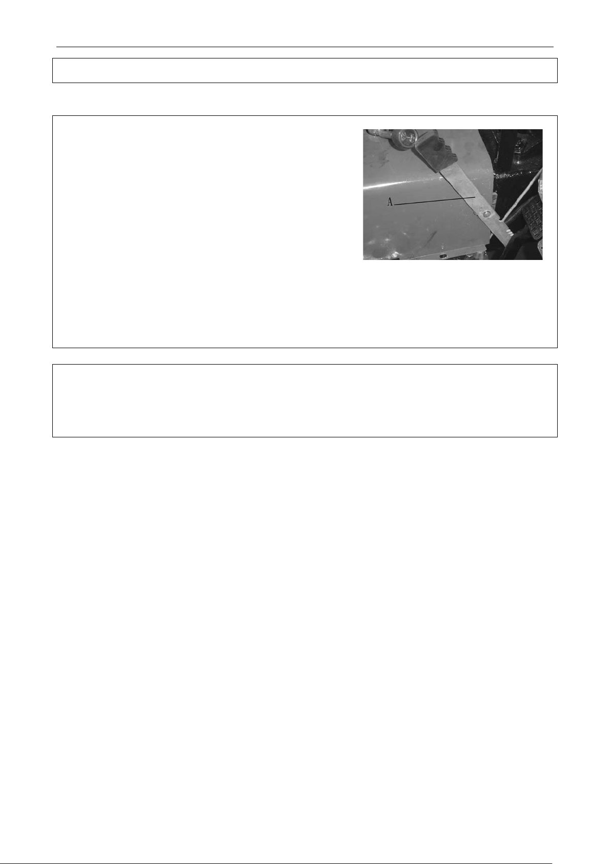
Figure 3-12 Start the tractor
condition. Otherwise troubleshoot it.
3.4 Start the tractor
Keep the engine runs with a low speed, depress the clutch
pedal and then place the gear lever of gearbox to a required
position.
Press the Parking brake handle A.
Whistle and determine there are no obstacles around.
Increase engine speed gradually and release the clutch pedal
slowly for smooth starting of the tractor. After starting, release
the clutch pedal rapidly to avoid clutch slips.
Gradually depress down the accelerator to allow the tractor to reach the needed working speed.
It is not allowed to reduce tractor travelin g spee d with the clutch half-engaged. Do not place your foot on the
clutch pedal during driving to avoid wears of quick release lever and friction lining.
Important:
wears. Prior to starting, it is necessary to release the parking brake to avoid operating component damages.
23
Page 33
3.5 Tractor steering
case of turn during tractor traveling, firstly press the horn switch on the steering column to give the
the case of tractor small turning or turning on soft ground, there may be steering failure due to front
wheel sideslip. At the moment, turn the steering wheel and depress the brake pedal at the corresponding
sided brake sharp turn. If the
front wheel sharp turning, causing the relief valve sounding squeak, the steering wheel
aulic steering system overload for a long
In the case of tractor turning in field operations or prior to tractor reversing, it is necessary
Depress the clutch pedal, push the shifting lever A forward from neutral position to shift to gear 3 or pull
1 or pull lever A backward to shift to reverse gear R. Shift the lever A to the left side from the neutral
3.5.1 In
signal, then turn the tractor. If the vehicle traveling at high speed, please decelerate. The tractor should be
turned slowly and early at the slow curve with the steering wheel less turned and then less returned. In the
case of a sharp turn, turn the steering wheel later and quickly and turn and return it largely.
3.5.2 In
side simultaneously to help steering.
Warning: 1. When tractor traveling at high speed, do not use the one-
should be returned back a little to avoid hydr
time. Otherwise doing so will lead to failure of steering and therefore accident.
Operation Instruction
2.
to lift operating components of the agricultural implement off the ground in order to avoid
agricultural implement damages or casualties.
3.6 Tractor gear shift
3.6.1 8+2 gear:
Main/Auxiliary gear shifting is controlled by 1 gear lever to realize the 8 gears. The main gear lever A can be
shifted to 4 gears(1,2,3,4) and 1 reverse gear R; the auxiliary gear lever B can be shifted to 2 speed zone (L is
low speed zone, H is high speed zone).
When depressing the clutch pedal, push the auxiliary gear B lever from the neutral position backwards to low
speed gear L or for war ds to high speed gear H.
lever A backward to shift to gear 4. Shift the lever A to the right side and then push it forward to shift to gear
position and push it forward to shift to gear 2.
Proper traveling speed not only get optimal production and economy, but also prolong the tractor service life.
It is not allowed for the tractor to work at overload state frequently. There must be some margin of power. In
case of field work, it is best for engine to run at about 80% of rated load. If tractor wor ks with light-duty
load and at not high speed, engage high 1gear and use small throttle to save fuel consumption.
24
Page 34
Operation Instruction
It is not allowed to use the differential lock during normal traveling and turning of the tractor to avoid
4DW tractor working in field with heavy load or working in damp and soft soil, the tractor traction
performance will be poor if driven only by rear wheels. Therefore, hooking the front drive axle could increase
In order to
push its control handle downward to release the front
could engage the front drive axle only on
:
3.7 Differential lock operation
Differential lock operation
During tractor traveling or operating, if it is trapped or slips and the tractor fails
to move forward, you can engage the differential lock according to the following
procedures for rigid connection of left and right drive shafts and then drive out
the slippery district with a constant engine speed.
Depress the clutch pedal, and engage the low speed gear.
Pull the throttle control handle to the position for the max. fuel supply.
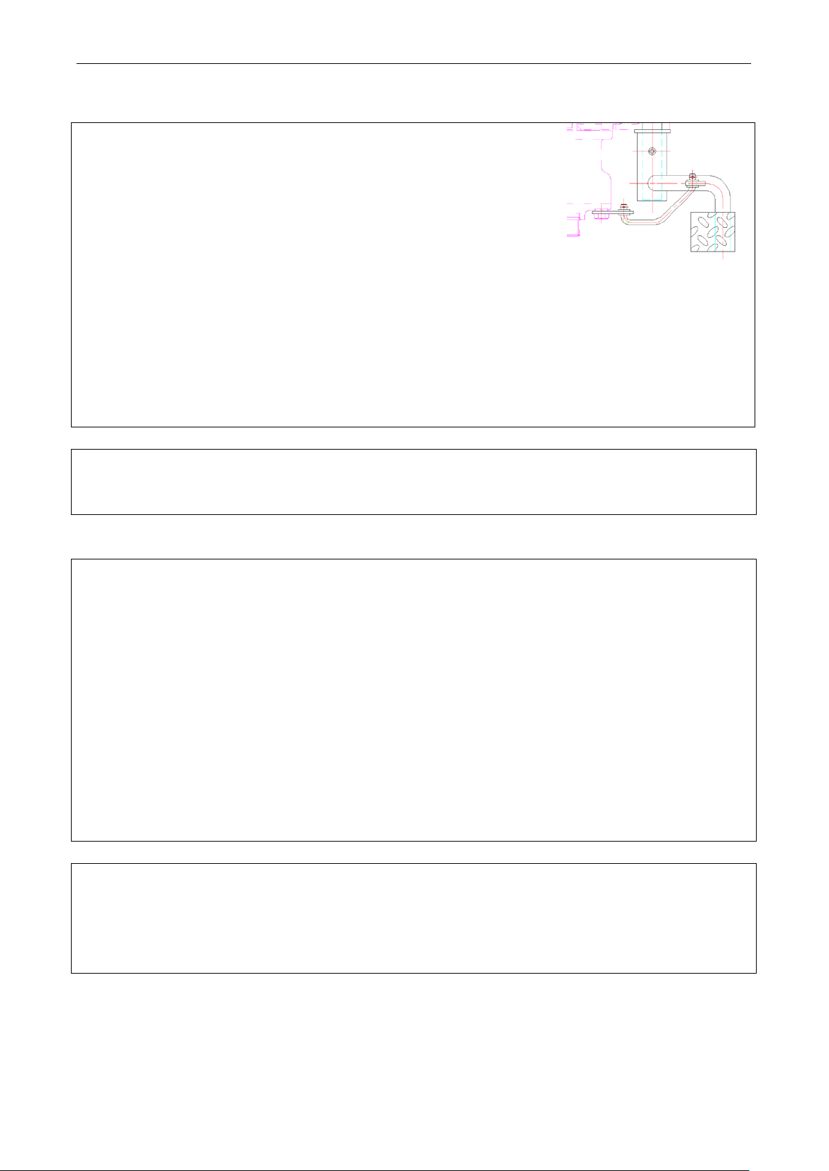
Put foot on the differential lock pedal A located on the right-lower seat.
Smoothly loosen the clutch pedal to slowly move the tractor.
After moving out of slipping section, release the differential lock pedal A to allow it return in position.
Important:
part damages and quick tire wears.
3.8 Front drive axle usage
If LOVOL
tractor tractive force, reduce the tire slipping rate and accordingly increase tractor adaptability.
facilitate to engage and separate the front drive axle, please follow the steps:
Connection of front drive axle
Figure 3-14 Differential lock
operation
Depress down the clutch pedal, engage the gearbox gear and then slowly release the clutch pedal. When tractor
slightly moving, timely pull the front drive axle control handle upwards to engage the front drive axle.
Disconnection of front drive axle
If disengaging front drive axle, depress down clutch pedal,
drive axle.
Important: If the tractor traveling on the pavement, it is not allowed to engag e front drive axle. Or else it will
give rise of early wear of front tires, increasing fuel consumption. You
slippery road or in rainy/snowy or if going long hill, the rear-wheel is easy to skid. After that, the front drive axle
should be disengaged.
Note
When the front tires wear quickly and the tire pattern on the left and right side have uneven wearing during
transportation operation of the tractor, exchange the left and right tires according to the circumstances.
25
Page 35
Operation Instruction
stly, depress the clutch pedal and then depress the
In the case of emergency stop, depress the clutch and brake pedals simultaneously. It is not allowed to
If equipped with trailer brake, please adjust the length of brake valve lever to firstly make trailer braking and
When the tractor traveling on pavement, do interlock the left and right brake pedals to
oil pump stops supplying oil and the engine shuts down immediately.
3.9 Tractor braking
3.9.1 Tractor braking
In general, it is necessary to reduce the throttle opening fir
brake pedal gradually according to specific condition to stop the tractor stably.
depress the brake pedal alone to avoid brake friction lining rapid wears or engine flameout.
then tractor.
3.9.2 Left and right brake pedal interlocking
When the tractor is running on the road, lock the left and right brake pedal together with interlock board.
Warning: 1. Before driving the vehicle, please make sure the brake can normally work. Otherwise,
there will be major accidents like brake failures.
2.
avoid tractor offset and even casualty.
3.10 Tractor stopping and engine flameout
Reduce throttle opening and tractor traveling speed.
Depress clutch pedal and then depress brake pedal. When the tractor stops, place gear lever of the gearbox at
neutral position.
Release the clutch pedal and brake pedal and reduce the throttle opening for engine idling.
Pull flameout control lever backward,
After that, push the lever to the position for oil supply.
Turn the ignition key to OFF to turn off all power supply.
26
Page 36
Operation Instruction
. Tire body fabric and cushion will be prone to adhesive
failure or the fabric is loose until tire is broken down, especially on the irregular pavement or cracked by
Too low pressure will distort the tire, quicken wear out tire surface and even quickly grind the inner and
Too low of tire
cause heavy control; too high of tire pressure may excessively stretch the tire fabric, possibly
causing crack, quickening tire wear and increasing the tractor body vibration. It is better to slightly decrease
period. The tire pressure should be measured by barometer at ambient temperature rather than when the tire
When removing and installing the tires, please use
3.11 Tire use and removal and installation
3.11.1 Tire use
Tire, as important parts, must be carefully used and serviced to extend its life as long as possible.
There is always a rated load value for a tire. If exceeding the rated value, the tire will severely be distorted,
excessive bending of tire side is prone to crack
obstacles.
Inflated tire pressure should meet the requirements. Too low or too high pressure will shorten the tire life.
outer tubes. Finally the core will be cut off and traveling resistance will be increased.
pressure may
tire pressure if field work ing. It is better to slightly increase tire pressure if traveling on pavement for long
is hot. Improper driving will cause early wear or damage of tires. During traveling, please avoid crossing the
obstacle at high speed, forcefully braking and sharp turning. If traveling on macadam pavement, please avoid
slip turning as possible as you can.
During traveling, please keep the tires away from chemical corrosion substance such as oil, acid or alkali etc.
It is not allowed to expose to sunshine to avoid the rubber aging.
Frequently check that front wheel alignment and tie-in are in position to avoid tire ir r eg ula r wea r. If the wear
of tire tread is not homogeneous, exchange the left and right tires.
Important:
Front and rear tire pressure of 4DW tractor should stay the same to avoid abnormal wear of tires.
3.11.2 Tire removal and installation
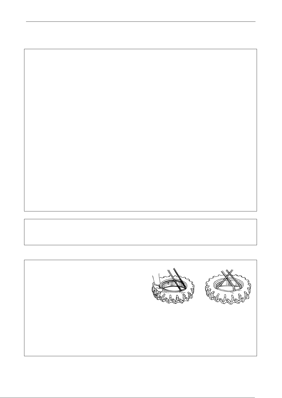
Tire removal
special tools rather than sharp too ls (such as screwdriver)
and large hammer to avoid piercing tires or damaging tire
edge and wheel rim.
If removing tube, please deflate, press the outer tube edge
into the rim groove, use the crowbar to lever the tire edge
Fig.3-15 Tire removal
around the core out of rim and then use another crowbar
to lever the whole tire edge. After taking out the inner
tube, use the same method to lever out the other side of
tire to take off the outer tube.
27
Page 37
Tire installation
oat a thin layer of
should be put into outer tube (slightly
Use crowbar to lever the other side of outer tube into rim (you may apply greater force at last phase, so use
If inflating, check whether the inner tube is pierced and use hammer to tap outer tube. It is better to inflate to
e could normally inflate and
Never remove the bolts of tire, drive wheel hub and wheel rim under inflation state, otherwise
working in dry farm or transporting, please increase the counterweight. If the tractor is used in mountainous or
During installing, c
talcum powder between the inner tube and
outer tube after cleaning each part.
Operation Instruction
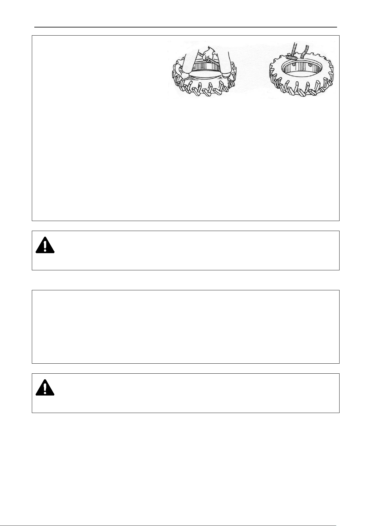
Put the tire on flat ground and install the
outer tube by foot or lever. The inner tube
Fig.3-16 Installation
shim up the outer tube) with lead wire to
fix the core into its hole to avoid skipping.
hammer to gently hit crowbar.)
At last check that core position is upright and the tire edge and rim is closely attached.
desired pressure, then deflate a half of air to inflate again. Thus the inner tub
eliminate puckering of outer tube.
Warning:
the bolts may be rushed out to hurt people.
3.12 Counterweight usage
The counterweight is dependent on tractor operating requirement. If the tractive force is needed to be increased for
hilly area, properly increase front counterweight to avoid “Wheelie” during work..
Rear counterweight is round cast iron piece with each piece mass of 28kg. 2 pieces can be installed at the left or
right. Thus the total mass of rear counterweight is 112kg.Front counterweight mass is 9kg each piece. 4 pieces can
be installed with total weight of 36kg.
Caution: If removing the rear wheel with rear counterweight, please remove the rear counterweight firstly
to avoid casualty caused by its instability.
28
Page 38
Operation Instruction
series tractor seats can be adjusted forwards and
Pull the adjusting handle A on the left of seat
For safety, you can adjust the seat only when the tractor is fully stopped to avoid potential
separated hydraulic lifting system and two kinds of adjusting types: position
The agricultural implement can be lifted or lowered by the control handle on
For the adjustment of agricultural implement at the height/lowest position, see
pin will stop the descent stop to push the handle back to neutral position. Finally the agricultural implement will
sing, lower the descent stop to
3.13 Drive’s seat adjustment
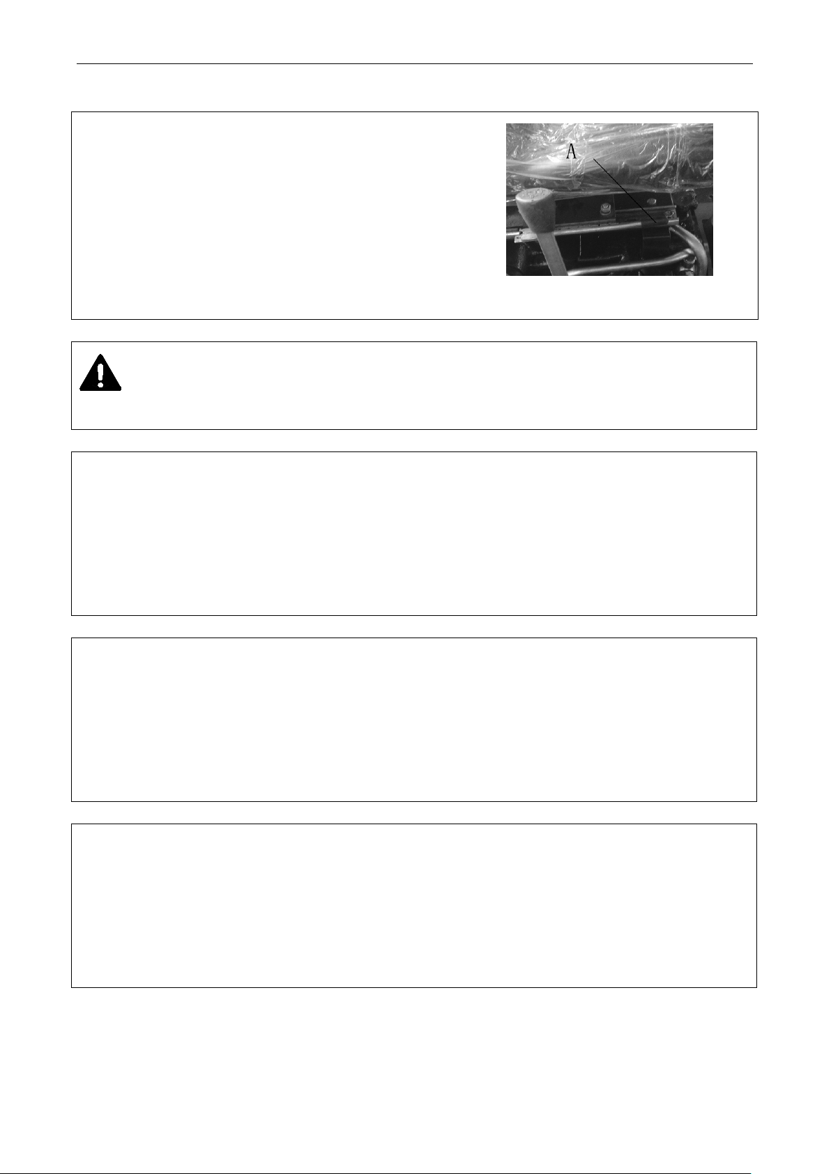
LOVOL
backwards.
outwards (as shown in figure 3-17), meanwhile move the seat
forward or backward to needed position. Then the handle A can
be released.
Caution:
hazard.
Fig.3-17 Drive’s seat adjustment
3.14 Use of hydraulic lifting system
TE series tractor employs semiadjustment and height adjustment.
the distributor. Pushing the handle forward can lower the agricultural implement; Pulling the handle backward can
lift the agricultural implement.
“Hydraulic lifting system adjustment”
3.14.1 Position adjustment
If equipped with agricultural implement without ground roller, please employ position adjustment. The tilling
depth is set by the descent stop position on the return-push rod. When using, the descent stop should be fixed at
preset proper position to allow the agricultural implement lower to preset tilling depth. At this time the retainin g
work at this tilling depth (for adjusting method, see “Hydraulic lifting system adjustment”)
3.14.2 Height adjustment
If equipped with agricultural implement with ground roller, please employ height adjustment. The tilling de pth is
controlled by the height from the ground roller to the bottom of plough. When u
lowest position to have the agricultural implement set at desired tilling depth. The handle is still at descent
position (For adjusting method, see “Hydraulic lifting system adjustment”).Finally the agricultural implement will
work at this tilling depth.
29
Page 39
Operation Instruction
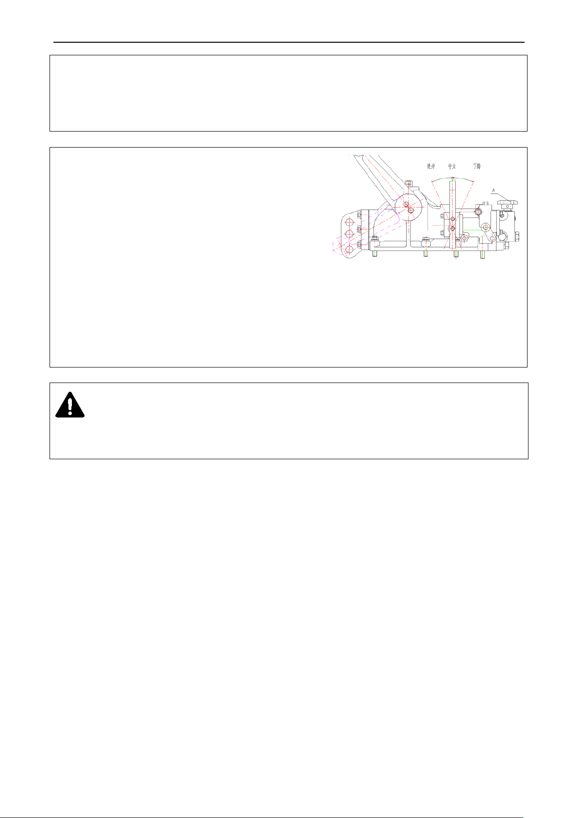
can be adjusted according to agricultural requirements and
The lifting stop and lowering stop is respectively control the lifting and lowering height of
.Select proper descent speed to avoid
damaging agriculture implement caused by impact when
weight of agricultural
Clockwise rotating the adjusting valve A can decrease the
Anticlockwise rotating the adjusting valve A can increase
When the tractor with agriculture implement traveling for a long distance, the agriculture
Note: The two return stop position on the push rod
equipped agricultural implement. The agricultural lifting/lowering height varies depending on the stop position on
the push rod.
agricultural implement.
3.14.3 Descent speed adjustment
The agricultural implement lowering speed can be controlled by
adjusting descent speed
agriculture implements contacting with ground. When delivery,
the descent speed adjusting valve is preliminarily adjusted. The
driver can readjust it according to
implement and ground hardness.
descent speed of agricultural implement.
Fig.3-18 Regulating valve schematic
the descent speed of agricultural implement.
Caution:
implement should be locked by using hydraulic lock to avoid it sudden falling and eventual accident caused by
moving distributor control handle.
30
Page 40
Operation Instruction
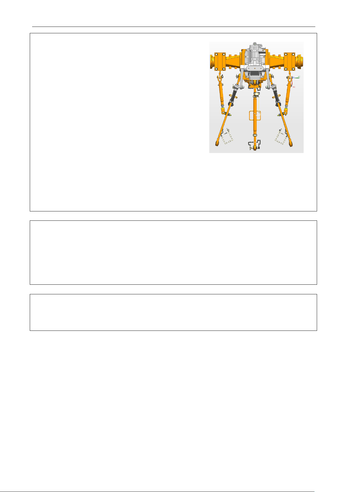
To ensure the consistent of ploughing depth, the plough should
If the front furrow is ploughing deeper than rear one or the
plough heel leaves ploughed groove, the upper pull rod
d. If the rear furrow is ploughing deeper
than front one, or the plough heel compacts the ploughed
Generally, the left lifting rod C is not needed to
gricultural implement not lifted to avoid damage of linkage. It is only allowed to steer
3.14.4 Use of Linkage
be adjusted at the longitudinal and horizontal position.
Longitudinal adjustment: adjust the length of upper pull rod
A to keep the plough frame level at longitudinal orientation.
should be extende
groove, the upper pull rod should be retracted.
Horizontal adjustment: adju st the length of left/right lift ing
rod to keep the plough frame level at horizontal. Extend the
right lifting rod B to increase the tilling depth of 1
retract the right lifting rod to decrease the tilling depth of 1
st
furrow;
Fig. 3-19 Linkage
st
furrow.
adjust. It is only used when the adjusting amount of right
lifting rod is insufficient to keep the depth consistent.
Important:
1. When tilling, the deflective traction of agricultural implement is not allowed by fixing limit lever to avoid
damaging the linkage.
2. No steering with the a
the tractor after furrow is lifted.
Note: when the tractor turning at the field edge, the limit rod is mainly used to avoid big swing of lower link that
could cause impacting the rear wheel of tractor. When agricultural implement working, the limit rod is slack to
allow some swing amount between the tractor and implement.
31
Page 41
Operation Instruction
rotates at the low speed, the battery could supply to tractor electrical equipment with accumulated electric
e pole and wire well connected. The air vent of plastic cover should be
3.14.5 Use of PTO
3.14.5.1 Use of PTO
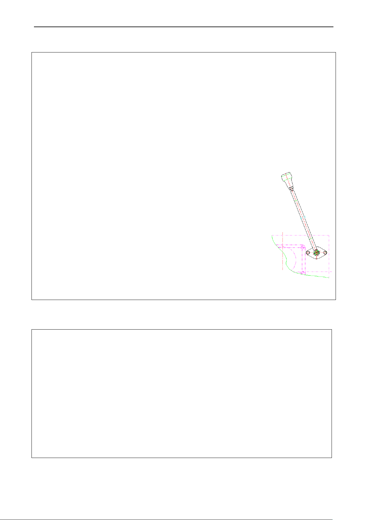
Engagement and cutting-off of PTO shaft is controlled by the lever at the left back side of transfer case. If pushing
the handle forward, the high speed gear is engaged; if pulling the handle backward, the low speed gear is engaged.
The concrete method is as follows:
Dismantle the hitched device and PTO protection cover to install the needed agricultural implement;
Place the PTO gear shifting handle to the needed gear position.
Depress the clutch pedal to release the clutch and shift the PTO shaft operation lever to desired position.
the tractor can work again;
In case the PTO is unnecessary, installed the shield of PTO shaft
Fig. 3-20 Operation of PTO
3.14.6 Use of electrical equipment
TE series tractor electrical system is of 12V, negative ground and double-wire system. For the electrical syste m
composition and circuit, please see fig.3-21.
3.14.6.1 Battery
Battery is used to accumulate the electric energy generated from the generator. If the generator does not work or
energy. If the generator is overloading for short time, the battery services to supply power.
95D31 maintenance-free accumulator can be optionally installed.
Clean the dust and sludge on the battery housing to avoid electric leakage. Make a check of crack and
electrolyte leakage to keep th
unclogged to avoid explosion.
Every time, the starting time should not exceed 5s to avoid electric discharging excessively.
If the tractor is not used for long time, please unload the battery to charge and maintain it.
3.14.6.2 Generator
1
Page 42

The generator should be matched with the regulator.
” ground. Do not reversely connect the negative/
The starter is allowed to work continuously and for long time. For this reason, the starting time is not
During starting, if the key is returned back yet the starter is still running, please immediately shut down
Silicon rectification generator adopts negative “—
positive poles of the generator, regulator and battery. Otherwise, it will burn out the generator and
regulator;
Never use the method of short-circuit fire save electricity to check whether the generator is working.
When parking, take out the ignition key to disconnect the connection between the generator and battery,
avoiding discharging for long time.
3.14.6.3 Starter motor
allowed to exceed 5s to avoid damage of starter.
In the moment of starting, i f you hear clean crash caused by meshing of pinion and flywheel gear ring,
please immediately return the key and then try again.
the engine and try again when trouble is solved.
Page 43
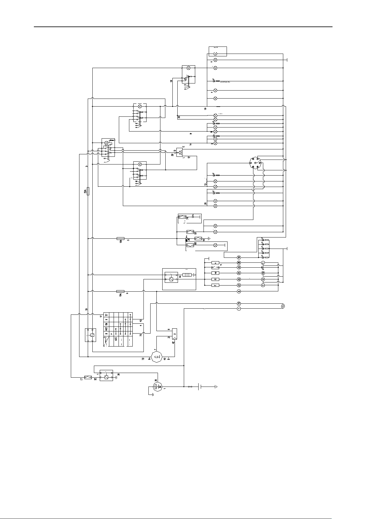
Operation Instruction
Rear positi on lamp
Instrument i ndicator lamp
Front position lamp
Backup lamp (K type
mudguard, 2 p ieces; com mon
mudguard, 1 piece)
Light switch
Directio n lamp ( L H )
Directio n lamp (RH)
Instrument i ndicator lamp
Instrument i ndicator lamp
High beam
Low beam
Electric flasher
Instrument i ndicator lamp
Instrument i ndicator lamp
(Lightin
g switch )
backup
switch
backup alarm
option
brake switch
(optional
spin-on alarm
switch
spin-on alarm l amp
(optional)
Instrument lamp
Tachometer
Oil pressure indicator
Oil pressure gauge
Fuel gauge Temperature gauge
Battery positive terminal
Ammeter positive terminal
Ammeter negative terminal
Oil pressure alarm
Preheating
relay
Preheating
plug
Regulator
Generator
Starter
60A fusible wire
Starting relay
starting switch
Current(A)
Locking 日 Ignition NO
Preheating H
Initial ST
main power
sully relay
License plate lamp
Gear
position
Lighting
switch
Brake
lamp
Other
Model of danger warning
switch
(选装)
)
Fig.3-21Circuit of electrical equipment
3
Page 44

3.15 Tractor running-in
for a time of period according to specified lubricating, speed and load
conditions. Meanwhile, the tractor should be checked, adjusted and maintained for normalization of its technical
in, carry out each shift and every 50h technical maintenances (see this manual 4
Check the oil level in the engine oil sump, drive system, lifter, main drive of front drive axle and final drive,
Use and Maintenance Manual”: from the low speed (small throttle) to middle speed (medium throttle) then to high
Place the engine accelerator control handle to medium throttle to keep the engine rotate at medium speed. PTO
Start engine, place the throttle to medium position and control the distributor handle to lift or lower linkage for a
Then mount 300kg substance or equivalent
agricultural implement to the linkage and allow the engine running at full throttle. Control the distributor handle to
Check whether the hydraulic hitch system is
with a low speed and test emergency brake application
load should be increased from lower value to higher value. The gear should be shifted from the low speed to high
Before using the tractor, it should run
state. Such a series of operations is called running-in.
3.15.1 Preparations for running-in
During running-
Maintenance Manual)
Check and tighten all bolts, nuts and screws outside of tractor.
Add the grease into the oil cup on the front wheel hub, front drive axle kingpin and water pump shaft.
fill it if necessary.
Fill up the fuel and coolant met required grade.
Check whether the tire pressure is normal.
Ensure all electrical element circuits are correct and reliable.
Place each handle at neutral.
3.15.2 Engine idling running-in
Carry out engine running-in with no load for 15min.Start the engine according to order descried in “Diesel Engine
speed (full throttle). Run it for 5min in turn.
During the engine idle running-in, please carefully check the engine, air compressor, hydraulic pump for normal
operation. If abnormal, please check if there is leakage of air, water and oil. Check the instrument for normal. In
case of abnormal, please stop immediately, troubleshoot and then run-in again.
You can start the following running-in only the engine is normally working.
3.15.3 PTO running-in with no load
respectively works at the low speed and high speed for 5min to check if there is abnormal phenomenon. After
running-in, the PTO should be placed at the neutral position.
3.15.4 Hydraulic system running-in
few times. Check whether any component is normal or not.
make the linkage lift or lower to full travel for 20 times or more.
fixed at max. height or desired position, needed time for lifting or lowering and any leakage.
With tractor at the same place, let the engine run respectively at the low, medium and high speed, whilst turn the
steering wheel to the left and the right respectively 10 times. Then observe the servo of front wheel steering to the
left and right. Inspect the sound for normal and whether steering wheel turning is easy and steady.
If any failures occur during running-in, please troubleshoot.
3.15.5 Tractor idling and running-in with load
As to the idle running-in, after the running-in of PTO and hydraulic hitch system, make sure the technical state of
tractor is completely normal and then carry out the entire tractor running-in according to table 3-2. During no-load
running-in, properly apply the single-side brake in turning
when running with a high speed.
After idle running-in, be sure the tractor technical state is normal and then carry out running-in with load. The
Page 45

Operation Instruction
speed. Please take note the following items during running-in:
essary to carry out cleaning and change all
lubricant and hydraulic system oil. Tractors are allowed to be put into service only after the completion of
opping engine that is still hot, please immediately drain the oil in the engine oil sump and steering
Also immediately drain the oil in the drive system, lifter and front drive axle to add proper light diesel
actor forward or backward at low speed for 3min. Or
jack up the front and rear wheels to let them free of ground, rotate the front and rear wheels forward and
Observe the electrical equipments and all instruments reading for normal.
Check the engine for normal running.
Check the clutch for smooth engagement and complete release.
Check the gearbox for easy and flexible gear shift without disordered gear engagement or automatic gear
disengagement.
Check the brake for reliable operation.
Check the differential lock for reliable locking and unlocking.
Check the front drive axle for reliable engagement and release.
When faults are detected, eliminate them and then go on implementing running-in.
3.15.6 Technical maintenance after running-in
After tractor running-in, there will be some metal particles o r contaminations mixed with lubricant of the drive
system, lubrication system and hydraulic system. Therefore, it is nec
necessary technical maintenance.
Technical maintenance content is as follows after running-in:
A fter st
oil reservoir. Clean the oil sump, oil filter screen , filter screen from diesel filter, oil filter, air cleaner and
steering oil reservoir. After replacing filter elements of diesel and oil filters. Fill the new lubricant as
technically required.
engine or kerosene. Without starting engine, drag the tr
backward for 3min, and then drain the cleaning solution timely. Dismantle the oil absorption filter o f lifter
to clean. After reinstalling, fill the drive system and front drive axle with the new lubricant as required.
Please service the diesel engine according to “Diesel engine use and maintenance instruction”.
Drain the cooling water, wash the engine cooling system with clean water and add new coolant.
Check the toe-in of front wheel, clutch, free travel of brake pedal, adjust it if necessary.
Check and tighten all bolts, nuts and screws outside of tractor.
For adding the grease, please refer to technical maintenance sheet.
Important:
1. In the case of tractors just leave the factory or be overhauled, they should be put into service after running-in
or their service life will be shortened.
2. Drivers should learn and master control method and usage of tractors before implementing tractor running-in.
Otherwise, there will be accidents as results of misoperation.
5
Page 46

Table 3-2 Running-in time at each phase(8F+2R chassis) Unit: h
Forward gear
Reverse gear
Low speed
1
Low speed
2
Low speed
3
Low speed
4
High spe e d
2
High spe e d
3
High spe e d
4
Idling
0.5
0.5
0.5
0.5
0.5
0.5
0.5
0.5
0.5
0.5
With trailer loaded
transportation
With plough working
ploughing depth:14cm
Gear position
with 1.2t goods,
in sandy land,
4 4.5 5 5 2.5
5 5 5 5 4
High spe e d1
Reverse 1 Reverse 2
Note: For 4-wheel driving tractor, all speed gears shall be engaged with front driving axle, except the high 4 speed
gear.
Page 47

Operation Instruction
Friction lining excessively wears out or is
readjust the free travel of pedal to
2. The clutch
could not be
released and
Free travel of pedal is too long and work
The three release lever heads are not at
the free travel of pedal to
when pulling
The three release lever heads are not at
3.16 Tractor common failures and troubleshooting
3.16.1 Chassis failure and troubleshooting
3.16.1.1 Clutch failure and troubleshooting
Table 3-3 Clutch failure and troubleshooting
Failure Cause Troubleshooting
1. Clutch
slips.
thoroughly
engaging
gives sound.
3. Tractor is
jouncing
out.
(1) There is oil co ntamination on the friction
lining and pressure plate
(2)
burnout.
(3) Spring pressure is too low.
(4) Free travel of pedal is too short or there is
no free travel.
(5) Driven plate of clutch is serious distorted.
6) The heads of three release levers are not on
a same plane.
(1)
travel is too short.
(2) Driven plate of clutch is serious warped.
(3)
the same level.
(4) Crushed friction plate
(5) Tight spline of friction plate
(1)
the same level.
(2) There is oil co ntamination on the friction
lining and pressure plate
(3) Driven plate is serious distorted.
(4) The fixin g bolts attaching the flywheel to
clutch housing are loose.
(1) Clean it with gasoline and troubleshoot
(2) Replace friction lining
(3) Replace spring
(4)
specification
(5) Replace driven plate of clutch
(4) Adjusting to specification
(1) readjust
specification
(2) Replace driven plate
(3) Adjusting to specification
(4) Change the friction plate
(5) Repair and adjust the spline
(1) Adjusting to specification
(2) Clean the friction lining and driven plate
(3) Replace driven plate
(4) Timely stop vehicle to troubleshoot
7
Page 48

3.16.1.2 Gearbox failure and troubleshooting
Shift block of gear lever seriously wears
Engaging sleeve end face and gear end
Troubleshoot it according related
Interlock link should be properly
Spring pressure of interlock pin is
The bearing on the gear shaft is worn out
Interlock link should be properly
Gear shifting guide plate groove seriously
Shift fork and shift groove of meshing
Gear excessively wears out, tooth face is
Lubricant is insufficient or the lubricant
1. Main drive
gives loud
2. Bevel pinion
bearing and
bearing are too
Table 3-4 Gearbox failure and troubleshooting
Failure Cause Troubleshooting
1. Gear
engagement is
difficult, or
failure
2.Auto gear
disengaging
3. Disorder gear
engagement
(1) Clutch is not thoroughly released.
(2) Interlock link is too long
(3)
out.
(4)
face are worn out or damaged.
(1) Interlock link is too short.
(2) Shift fork shaft groove seriously wear out.
(3)
insufficient.
(4)
to have the shaft inclined.
(5) Gear block spline wears out.
(1) Gear lever knob seriously wears out.
(2)
wears out.
(3)
sleeve wears out.
(4) Serious worn gear or spline.
(1)
means
(2)
shortened.
(3) Replace gear lever
(4) Repair of replace it
(1)
extended.
(2) Replace shift fork shaft
(3) Adjust or replace interlock pin spring.
(4) Replace bearing.
(5) Replace gear block
(1) Replace or repair gear lever
(2) Replace gear shifting guide plate.
(3) Replace shift fork and meshing sleeve.
(4) Change the worn parts
(1)
peeling off or breakage.
4. There is
noise or knock
in gearbox.
(2) Bearing seriously wears out or is damaged.
(3)
quality does not satisfy the regulation.
(4) Shaft spline and gear spline hole are worn.
3.16.1.3 Rear axle or brake failure and troubleshooting
Failure Cause Troubleshooting
(1) Bevel pinion bearing play is excessive.
(2) Gear engagement is abnormal.
(3) Bevel gear pair bearing or gear is
damaged.
noise.
(4) Differential bearing is worn out or stuck.
(5) Planet gear or shim is worn out.
(6) Differential bearing is worn out or
damaged.
(1) Preload is excessive.
differential
hot.
(2) Lubricating is poor
(3) Bevel gearset pair play is too narrow.
(1) Replace gear
(2) Replace bearing.
(3) Change lubricant or fill it up.
(4) Change the worn parts
Table 3-5 Rear axle or brake failure and troubleshooting
(1) Readjust to specification
(2) Readjust to specification
(3) Replace bearing or gear
(4) Replace differential shaft
(5) Replace planet gear or shim.
(6) Replace differential shaft
(1) Readjust the bearing preload.
(2) Check the lubricant level, and add it if
necessary.
(3) Readjust the gear backlash.
Page 49

3. Final drive
gives abnormal
noise.
Brake pads are excessively or
6. When
braking, the
tractor offset
Front tires are
Front shaft is
Operation Instruction
(1) Bearing, gear or shaft is damaged. (1) Replace bearing, gear or shaft.
(1) Free travel of brake pedal is excessive.
(2)
eccentrically worn out.
4.Braking fade
(3) Free travel of brake pedal is excessive.
(4)Brake pad is polluted by oil
5. Brake is hot (1) Brake pads do not return.
(2) the brake pedal fails in returning
(3)Small free path of brake pedal
(1) Free travels of left and right brake
pedals are not the same.
(2) Brake friction plate of one side is worn
or polluted by oil
occurs.
(3) The front and rear tire pressures are not
(1) Readjust the free travel of pedal
(2) Replace brake pads
(3) Readjust the free travel of pedal to
specification
(4)Wash with gasoline and remove oil leak
(1) Replace return spring
(2) Adjusting to specification
(3) Adjusting to specification
(1) Adjustment
(2) Change or wash the friction plate and
remove oil leak.
(3) Check and inflate it to specified pressure.
consistent.
3.16.1.4 Traveling system failure and troubleshooting
Table 3-6 Traveling system failure and troubleshooting
Index: Failure Cause Troubleshooting
1.
2
seriously worn out.
swing.
(1) Front wheel rim or spoke is seriously
distorted.
(2) Toe-in is not well adjusted.
(3) Steering knuckle and two clevis pins
with heads of cylinder are severely
worn out.
(4) Tire inflation is insufficient during
transportation.
(5) Front drive axle is not disengaged
during transportation.
(6) Front drive wheel tire tread is
reversely installed.
(1) Fixing nuts and bolts attaching ball
pin, cylinder and steering rocker are
loose.
(2) Toe-in is not well adjusted.
(3) Bearing clearance is excessive or
severely worn out.
(4) Front wheel rim is seriously distorted.
(1) Correct front wheel rim or
spoke.
(2) Adjust the toe-in
(3) Replace clevis pins with heads.
(4) Check and inflate it to specified
pressure.
(5) Release front drive axle
(6) Readjust the wheel to
specification.
(1) Check and tighten it.
(2) Adjust the toe-in
(3) Check or replace bearing.
(4) Correct front wheel rim.
9
Page 50

3
wheel drive
Drive shaft
protective bushing
fer case is
The rubber washer at each oil pipe connector or
, stator or rubber ring of rear cover
Replace rubber washer or
Clean and replace rubber
The oil supply pumped from the gear pump is
insufficient. There is leakage in the gear pump or
the filter screen in the steering oil reservoir is
ering wheel, the cylinder
Relief valve spring elastic force weakens or the
Check the gear pump is
the air in the
system, check whether
there is air in the oil
Clean the relief valve and
adjust the relief valve
Use specified grade
Rotor and universal drive shaft are reversely
Replace universal drive
The noise is large.
(Fourtractor)
(1) Front main drive gear meshing mark
is poor.
(2) Main drive bearing clearance is
excessive or damaged.
(3) Differential shaft is worn out or
damaged.
(4) Planet gear or shim is worn out.
(5) Final drive planet gearset meshing
mark is poor.
(1) Readjust the gear meshing
mark.
(2) Repair of replace it
(3) Replace differential shaft
(4) Replace planet gear or shim.
(5) Replace planet drive gear
(1) Drive shaft is severely bend or
4
is hot. (Four-wheel
drive tractor)
5
1. The noise in the
trans
loud. (Four-wheel
(1) The high speed gear is higher than
(2) Bearing or gear severely wears out.
drive tractor)
3.16.1.5 Hydraulic steering system failure and troubleshooting
Table 3-7 Hydraulic steering system failure and troubleshooting
Index: Failure Cause Troubleshooting
(1)
bolt is loose.
1
Oil
leakage
(2) Valve body
interface is damaged.
(3) The rubber washer of shaft journal is damaged.
(4) Bolt attaching steering gear joint is loose.
(1)
clogged. Steering at low speed is light and steering
at high speed is heavy.
(2) When turning the ste
moves sometimes.
Steering is
2
heavy.
(4)
steel ball sealing is invalid. Light-duty steering is
light and heavy-duty steering is heavy.
(5) Oil viscosity is too thick.
(6) Steel ball check valve in the valve block is invalid.
3
Steering
failure.
Steering wheel is heavily turned at high speed and
at low speed, as well as with powerless of steering.
(7) oil leak (inside and outside the cylinder)
(1) The pull pin is broken or distorted.
(2) Opening of linkage shaft is broken or distortion.
(3)
installed.
distorted, causing friction.
real speed.
(1) Correct of replace drive shaft
(1) Engage low speed gear
(2) Repair of replace it
(1)
tighten the bolt.
(2)
washer.
(3) Replace rubber washer.
(4) Tighten bolts
(1)
normal and clean the filter
screen.
(2) Empty
absorption pipeline.
(4)
spring pressure.
(5)
lubricant
(6) Maintain or replace related
parts
(7) Check and remove the oil
leak
(1) Replace the pull pin.
(2)
shaft
(3) Reinstall it
Page 51

Operation Instruction
(4) Steering cylinder piston or piston sealing ring is
(4) Replace piston or sealing
The clearance between the rotor and stator is
position. When manual steering, steering wheel
e valve core and valve
Clearance between universal drive shaft and pull
Clearance between universal drive shaft and rotor
The filter screen of oil filter is
There is air in the oil absorption
The elastic pin at outmost or
nermost of control handle comes
Swing lever in the distributor
Main control valve is stuck at
neutral or lowering position or the
oil return valve is stuck at opening
The pin is shorten or the lowering
opening the
The oil pipeline from the cylinder
Open the distributor and install the
Dismantle the distributor to clean all
Remove the descent valve clogging,
readjust the clearance of descent valve
pull pin or tighten the descent valve
There is air in the oil absorption
(4) Gear pump is severely worn out,
(4) Repair or replace gear pump
damaged.
(1)
excessive.
(2) In case of power steering, the driver can not
obviously feel that the piston is already at extreme
4.
There is no
manual
steering
rotates but the cylinder does not.
(1) The clearance between th
sleeve is excessive.
(2)
pin is excessive.
(3)
5.
Insensitive
steering
is excessive.
(4) Return spring leaf is broken or too soft.
3.16.1.6 Hydraulic hitch system failure and troubleshooting
Index: Failure Cause Troubleshooting
(1) The oil le vel in the lifter hou sing is
(2)
(3)
(4) Gear pump is invalid.
(5)
Hydraulic
hitch system
(6)
could not
1
lift neither
(7)
at light duty
nor at heavy
duty.
ring
(1) Replace stator and rotor.
(2) Replace piston sealing ring
(1) Replace it
(2) Replace it
(3) Replace it
(4) Replace it
Table 3-8 Hydraulic hitch system failure and troubleshooting
(1) Fill oil to specified level.
too low.
(2) Replace or replace filter screen.
severely clogged.
(3) Check the pipeline joint.
pipeline.
(4) Check, repair or replace gear pump
(5) Reinstall elastic pin.
in
off.
(6)
comes off.
swing lever.
(7)
valves
position.
(8) Main control valve is stuck
(9) lowering valve is stuck
(10)
valve assembly is loose and rotated
out, causing unlowering valve.
(11)
head to cylinder is closed.
It could rise
at light-duty.
While it
2
could not
rise or rise
slowly at
heavy-duty.
(1)
pipeline.
(2) Adjusting pressure o f system relief
valve is too low.
(3) Adjusting pressure of cylinder relief
valve is too low.
(8) Clean the main control valve.
(9) Clean the lowering valve.
(10)
assembly.
(11) Open the oil pipeline.
(1) Check the oil absorption pipeline and oil
filter.
(2) Repair of replace system relief valve.
(3) Adjust of replace cylinder relief valve.
11
Page 52

Index: Failure Cause Troubleshooting
causing insufficient pressure.
There is oil leakage from the
There is air in the oil absorption
Troubleshoot the leakage at the
There is oil leakage from the
The sealing ring between the
distributor or cylinder head and oil
inlet of lifter housing is not well
The adjustment is not correct,
Firstly measure the lifting height of
force/position adjusting lever to let
lifting extreme position is lower than
The sealing between front taper
body of the descent speed control
control valve and taper hole. Or replace
to the lowest position and cut off inlet
oil line of oil tank. Then push control
3
4
The
agricultural
implement is
joggling
during
lifting at
slow speed.
After lifting
the
agricultural
implement,
it frequently
“Nods”.
Descent
speed only
under
self-weight
condition is
fast after the
engine
flameout.
(5)
cylinder sealing ring.
(1) The oil filter is clogged.
(2)
pipeline.
(3) Gear pump is invalid.
(4) The hydraulic oil level is too low.
(1) Distributor one-way valve sealing is
poor.
(2) The lowering valve sealing is poor.
(3) Cylinder relief valve is leaking oil
or improperly adjusted.
(4)
cylinder piston O- ring.
(5)
installed or damaged.
(5) Replace cylinder sealing ring
(1) Replace or clean filter element
(2)
connector and O-ring.
(3) Replace gear pump
(4) Fill lubricant to specification.
(1) Clean the one-way valve and face it up
if necessary.
(2) Clean or face up the descent valve
(3) Adjust or readjust cylinder relief valve.
(4) Replace O-ring.
(5) Check and replace sealing ring
5
With the
handle at the
lifting
position, the
distributor
(1)
causing the inner lifting arm against
lifting housing to have the relief
valve opened.
(1)
agricultural implement, then readjust the
original position.
gives sharp
sound.
(1) Clockwise tighten the descending speed
control hand wheel.
(2) Repair and face up the sealing between
the front taper body of descending speed
the descend speed control valve.
(3) Push lifter control handle to “Lowering”
position in order to lower outer lift ar m
6
There is no
hydraulic
output at the
cylinder
head or the
hydraulic
output is
(1) The inle t pipe to cylinder is not cut
off.
(2)
valve and taper hole is poor.
(3) The lifter is at neutral position
powerless.
handle to “Lifting” position.
3.16.1.7 Air brake system failure and troubleshooting
Table 3-9 Air brake system failure and troubleshooting
Index: Failure Cause Troubleshooting
Page 53

Operation Instruction
Relief valve could not be tightly
off brake
Return spring is broke or its elastic
Repair it to make tappet movement
does not
Cable joint is loose or ground wire is
The control circuit such as starting
tator are not
Starter motor circuit is open, short
Tighten the connection and remove
Adjust the spring pressure of carbon
starting is
start the
Communtator surface is burned or
The carbon brush excessively wears
out or the spring pressure of carbon
brush is insufficient, causing it poor
Bearing is severely worn out, the
Smooth the communtator surface to
Index: Failure Cause Troubleshooting
(1) Air is leaking out of pipe.
(2) Exhaust valve plate of air pump wears
Air pressure
1
is
insufficient.
out or the spring is damaged.
(3) Air pump piston ring or cylinder liner
severely wears out.
(4) Air pressure alarm is fault.
(5)
closed.
(1) The dust enters the air cut-
valve
(2) The oil or water enters the air cut-off
brake valve
2
The air
cut-off
brake valve
does not
reset
3
The air
cut-off
brake valve
does not
(1) Tappet is stuck.
(2)
force is weakened.
exhaust
3.16.2 Electrical system failure and troubleshooting
3.16.2.1 Starter motor failure and troubleshooting
(1) Check and troubleshoot the air leaking
points.
(2) Replace it
(3) Replace piston ring and cylinder liner.
(4) Replace or repair air pressure alarm.
(5) Check or replace relief valve.
(1) Clean the air cut-off brake valve
(2) Drain th e oil or water in air reservoir.
Clean air cut-off brake valve.
(1)
flexible without stuck.
(2) Replace return spring
Index: Failure Cause Troubleshooting
Generator
1.
rotate.
Starter
motor
2
powerless
or can not
engine.
Table 3-10 Generator failure and troubleshooting
(1) Battery power is insufficient.
(2) Dirty battery plate or loose cables.
(3)
rusted.
(4)
switch etc is disconnected.
(5) The carbon and commun
well-connected.
(6)
circuit.
(1) Battery power is insufficient.
(2) Cable is not will connected.
(3)
contaminated with oil.
(4)
connection with communtator.
(5) Main contact point of solenoid valve is
burnout and not well connected.
(6)
armature is against its housing.
13
(1) Charge the battery as specified.
(2) Clean dirt and tighten connections.
(3)
the corrosion.
(4) Check the circuit for reliability.
(5)
brush and clean the communtator.
(6) Repair starter motor
(1) Charge the battery as specified.
(2) Tighten the wire connection
(3)
clean oil contamination.
(4) Replace or adjust it
(5) Polish it with “0” nonmetal abrasive
paper
(6) Replace bearing.
Page 54

Index: Failure Cause Troubleshooting
started, but
motor is
Copper contact disc is stuck with the
Starter motor armature is broken or
air contact
(1)
two contact points in the starter motor
The engine
is already
starter
3
till
running,
giving
sharp
noise.
relay.
(2) Starter motor lever is released out of
hook or eccentric screw is loose.
(3) Lever return spring is broken or loss of
elastic force.
(4)
bent.
(5) The gear is stuck by galling
(6) The contact point of starting relay is
stuck.
(7) After star ting, the ignition switch d oes
not reset.
(1) Check circuit and rep
points.
(2) Readjust and fix it.
(3) Replace spring
(4) Repair starter motor
(5) Smooth gear face
(6) Replace starter motor
(7) Replace the ignition switch.
Page 55

Operation Instruction
Repair of replace generator
Carbon brush is not well connected.
Battery electrolyte is excessive low or
3.16.2.2 Generator failure and troubleshooting
Table 3-11 Generator failure and troubleshooti ng
Index: Failure Cause Troubleshooting
1
2
3
Generator can
not generate
electrical
energy.
Generator can
not charge the
battery
sufficiently.
Generator
charging
current is too
high, opting
to burn the
bulb.
(1) Cable is not well connected or reversely
connected or disconnected.
(2) Rotor circuit is open.
(3) The rectification diode is damaged.
(4) Carbon brush is not well connected.
(5) The regulator is damaged.
(1) The driving belt is slacken.
(2)
There is oil contamination on slip ring.
(3) The regulator is damaged.
(4)
sulfuration is severe or the battery is too
old.
The voltage of regulator is too high.
(1) Repair circuit
(2)
assembly.
(3) Replace the diode.
(4) Remove the dirt or replace carbon
brush
(5) Repair of replace regulator.
(1) Adjust the drive V belt tension
(2) Adjust the carbon brush and clean
the slip ring.
(3) Replace regulator.
(4) Refill the electrolyte to specified
height. If the sulfuration is severe
and can out be recovered, replace
it.
Replace voltage regulator.
15
Page 56

3.16.2.3 Battery failure and troubleshooting
he battery
power is
insufficient and
difficult to start
The circuit between pole plates is
The terminal is not well connected.
Clean the deposition and replace
Clean the vulcanization by repeatedly
Tighten the connection. Clean the
thin layer of Vaseline
2. Discharging
current is too
Electrolyte is spilled out of battery,
causing shortcut of positive and
Place the metal tool or lever between
the positive pole and negative pole,
or the active material deposits too
ged, causing
Wipe the battery surface and poles with
alkaline water or warm water to keep it
Do not lay the metal rod or tools on the
Circuit is open. Connector is not
Water temperature sensor is
Water temperature sensor is
Table 3-12 Battery failure and troubleshooting
Failure Cause Troubleshooting
T
engine.
high.
(1) The electrolyte is too low.
(2)
short-cut.
(3) Vulcanization of pole plate occurs.
(4)
There is too much oxidate on the pole.
Charging power is insufficient.
(1) There is foreign material in electrolyte
(2) There is short circuit outside of battery.
(3)
negative poles.
(4)
causing severe shortcut.
(5) The active material is off of pole plate
much, causing the shortcut of pole plate.
The insulator is dama
shortcut of pole plate. The pole plate is
warped, causing battery shortcut.
(1) Replace battery
(2)
electrolyte.
(3)
charging and discharging the battery.
(4)
oxidate to coat a
on the pole.
(1) Replace battery
(2) Find out the shortcut circuit to solve the
problem.
(3)
clean (do not let the water enter battery)
(4)
surface of battery.
3.16.2.4 Instrument failure and troubleshooting
Index: Failure Cause Troubleshooting
Water
temperature
1
gauge pointer
always points to
low temperature
zone.
Water
temperature
2
gauge pointer
always points to
high temperature
zone.
Oil pressure
gauge could not
3
4
indicate
normally.
Barometer
could not
indicate
normally.
Table 3-13 Instrument failure and troubleshooting
(1)
well connected.
(2)
damaged.
(3) Water temperature gauge is fault.
(1)
damaged by shortcut.
(2) There is shortcut in all circuits.
(3) Water temperature gauge is fault.
(1) There is shortcut or open in circuit.
(2) Sensor circuit is open, shortcut or not
well connected.
(3) Oil pressure gauge is fault.
(1) Instrument is damaged.
(2) Air is leaking out of pipe.
(1) Repair the circuit and clean the dirt
at the connector.
(2) Replace water temperature sensor.
(3) Replace instrument.
(1) Replace water temperature sensor.
(2) Check and solve failure of short-cut
circuit.
(3) Replace instrument.
(1) Troubleshoot it.
(2) Repair of replace sensor.
(3) Replace instrument.
(1) Repair of replace instrument.
(2) Repair of replace air pipe.
Page 57

Operation Instruction
n or the
Dimmer switch is not well
Backup lamp switch is not well
3.16.2.5 Lamp failure and troubleshooting
Table 3-14 Lamp failure and troubleshooting
Index: Failure Cause Troubleshooting
(1) Check and repair the circuit.
(2) Repair or replace it
(3) Replace with high quality bulb.
(1) Check and repair the circuit.
(2) Repair or replace it
1
2
There is no
high and low
beam in
headlamp
Backup lamp
can not go on.
(1) Circuit is shortcut or ope
fuse is burnout.
(2)
connected or damaged.
(3) Filament is burnout.
(1) Circuit is open.
(2)
connected or damaged.
17
Page 58
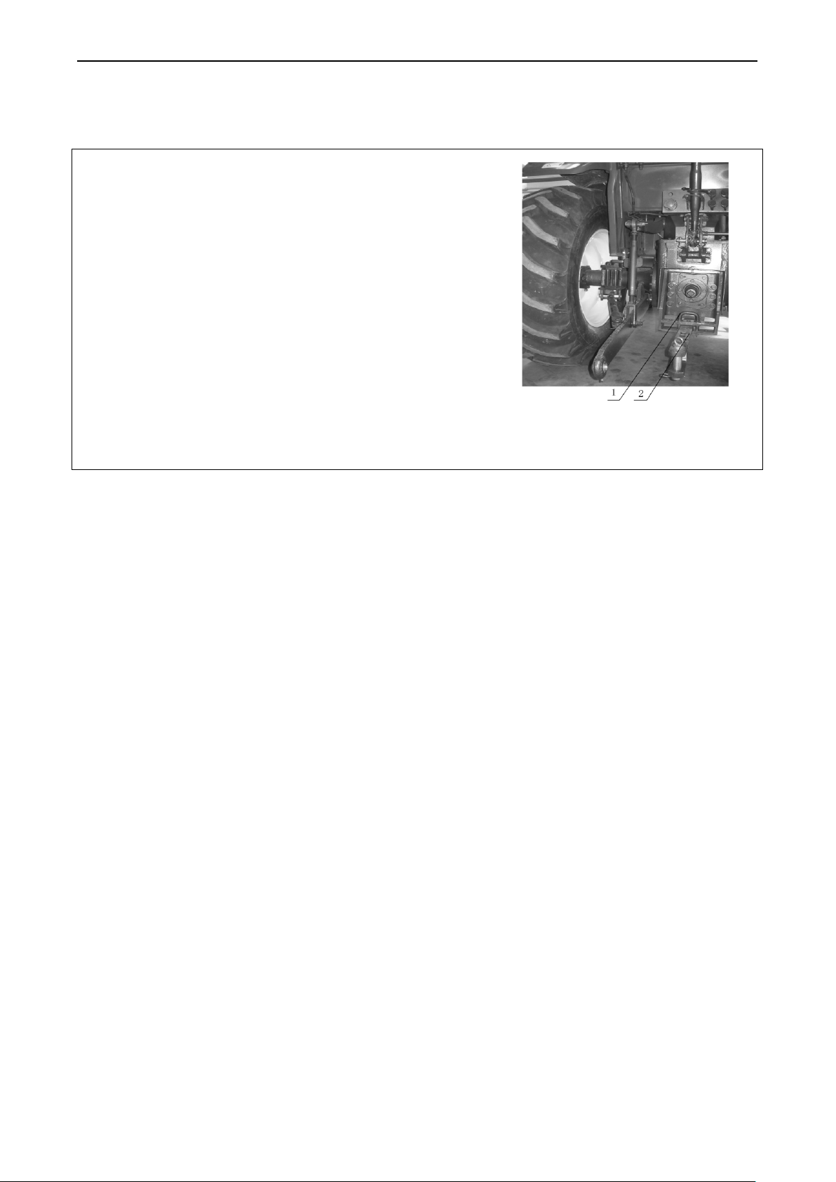
Accessories and spare parts
is connected to Implement by traction pin. This tow bar can
horizontally swing to hook with implement in an easy way. In
operation, the tow bar can swing from left to right. However,
pin (1) must be inserted in the bore on towing plate to
when tractor trailing
The height of towing point can be changed by turning over towing
4 Accessories, Spare and Wearing Parts
4.1 Accessories and spare parts
4.1.1 Cab (Optional)
The LOVOL tractor can be equipped with safety frame in order to
provide a comfortable operating environment for the driver.
4.1.2 Tilting tow bar (Optional)
It is only used for towing agriculture implemtns. The after tow bar
locating
prevent it from swinging (See Fig.4-1)
implement reverses.
bar in order to reach appropriate height for supporting implement.
Fig.4-1 Application of tilting traction
1. Locating pin 2.Tilting tow bar
47
Page 59
4.1.3 Vehicle tool schedule
6×150P Cross recessed head
The Technical Document for
Provided by the engine
Provided by the engine
spare parts and documents provided with engine, it is necessary to
Accessories, spare and wearing parts
Table 4-1 Vehicle tool schedule
Item
No.
1 JB/T 7942.1 Strut-type oil gun A100 1
2 QB/T 2564.4
3 QB/T 2564.5
4 GB/T 4388 Double-head wrench 10×13×135 1
5 GB/T 4388 Double-head wrench 16×18×183 1
6 GB/T 4388 Double-head wrench 21×24×223 1
7 GB/T 4388 Double-head wrench 27×30×244 1
4.1.4 Vehicle part schedule
Item
No.
1
Code Name Quantity Remark
1×5.5×125PSlotted-head
screwdriver
screwdriver
Table 4-2 Vehicle part schedule
Code Name Quantity Remark
TD9600000700
Fuse 10A 1
1
1
2
3
4
4.1.5 Vehicle document list
Item
No.
1 The User Manual of Tractor 1
2
3 Product Qualification Certificate 1
4 The Product Certificate of Engine 1
5 Tractor spare parts Atlas 1
6 Warranty Services certificate 1
TD9600000800
TD9600000900
TD900.484.3
Table 4-3 Vehicle document list
Code Name Quantity Remark
Engine
Fuse 15A 1
Fuse 20A 1
Back trailer latch 1
1
parts manufacturer
parts manufacturer
7 Engine spare parts box 1 Engine Belt
8 A packing list of vehicle items 1
Note: For acceptance inspection of the tools,
48
Page 60
Accessories and spare parts
comply with packing list of diesel engine.
All various spare parts, tools and wearing parts are special parts used for this machine. Take good care to
During maintenance and service for machine, you must use standard accessories provided by official
s, the machine will be impacted on functions, performance
4.2 Wearing parts
The wearing parts of LOVOL series wheeled tractor include: Table 4-2 Fuse and parts listed in the table below
Table 4-4 Wear parts (such as bubble, rubber etc) list
Item
No.
Code Name Quantity Remark
1 12V-1141-28W Rear work lamp bulb 1
2 12V-1141-21W Front/rear steering light bulb 4
3 12V-89-5W position lamp bulb 2
4 12V-H4-55/60W
Distance-light double filament
bulb
1
5 12V-1141-21W brake lamp bulb 2
6 TE324.20A-01 Thread rubber ring 1
7 FT220.40.301 Steering rod protective bush 1
8 TE250.362D-01 Dust ring 1 for shuttle shift model
9 FT250.47C.230 Hood seal 1
10 TE250.475B-01 adhesive tape 1
Important instruction:
1.
store and prevent from loss in order to use, repair and maintenance for machine; if they are lost carelessly, it
is possible to lead machine functions and performance degradation.
2.
manufacturer; if used non-standard accessorie
and service life, even creating a potential safety hazard.
49
Page 61

Maintenance Instructio n
Never adjust the relief valve opening pressure of engine, hydraulic system and air brake system, and opening
(every 10h), every 50h, 200h, 400h, 800h, 1600h, special
Check the main bolts and nuts outside tractor for looseness, especially the nuts of front and rear wheels.
iesel engine use and
5 Maintenance Instruction
Technical maintenance covers a series of technical maintenance such as cleaning, checking, lubricating, fastening
each part or replacing some parts etc. Good technical maintenance could slow down the deterioration of technical
state for each part to reduce the failure and to prolong the service life, which could ensure the tractor works in good
state.
Important:
1. All maintenance should be carried out by the person specially trained and be familiar with machine features to
avoid the damage of tractor.
2. Please strictly follow the technical maintenance procedures to ensure the tractor normal work and to prolong its
service life.
3. In the warranty period of tractors, if non-professional personnel who are not familiar with the characteristics of
this machine conduct the maintenance, or in the maintenance period specified by the manufacturer no
maintenance work has been done according to the requirements, then the damage to the tractors will result in the
loss of the related right of the three guarantees of this tractor.
4.
pressure of radiator cap without permission. Otherwise it will damage the tractor, reduce the machine
performance and then lose related “Three Guarantees”.
5.1 Technical maintenance procedures
According to the accumulated working hours, the LOVOL series wheeled tractor technical maintenance procedures
are classified into the following level: each shift
maintenance in winter and maintenance for long-time storage.
5.1.1 Technical maintenance at each shift.
(1) Clean the dirt and oil contamination on the tractor; If working in the dusty environment, please clean the air
cleaner.
(2)
Tighten them if necessary.
(3). Check the fluid level in the oil sump, radiator, fuel tank and hydraulic lifter and battery etc and fill the m if
necessary. If checking the level in oil sump, please go ahead after stopping and waiting for 30min.
(4) For adding the grease, please refer to maintenance sheet 1.
(5) Check the tractor for leaking of air, oil, water etc. If so, please troubleshoot.
(6) Check the front and rear tires pressure and inflate them if necessary.
(7) Check and adjust the free travel of clutch pedal and brake pedal.
(8) Please service the diesel engine according to the “Daily maintenance” in “D
maintenance instruction”.
5.1.2 Technical maintenance every 50h
(1) The whole content of technical maintenance each shift should be completed.
(2) Check and dedust the oil surface of oil-bath type air cleaner.
(3) Check the tension of fan belt. Use finger to press the belt and the distance should be (15~20)mm. If not,
adjust it.
(4) Coat grease on the battery terminals to avoid corrosion.
(5) Open the clutch drain plug to drain the deposited oil.
(6) Please service the diesel engine according to the “Stage I technical maintenance” in “Diesel engine use a nd
maintenance instruction”.
50
Page 62

Maintenance Instruction
in and tightness of front wheel bearing. Adjust it if necessary.Change
Please service the diesel engine according to the “Stage III technical maintenance” in “Diesel engine use
Fully clean the radiator with 25% concentration Hydrochloric acid solution, and then use water to clean it
Please service the diesel engine according to the “Stage IV technical maintenance” in “Diesel engine use
Check whether the main drive gear backlash and meshing mark are normal. Inspect the bearing clearance
After maintenance, carry out the commissioning for a short time to check the working status of each
5.1.3 Technical maintenance every 200h
(1) The whole content of 50h technical maintenance should be completed.
(2) Please change oil in diesel engine oil sump and then clean the oil sump, oil absorption disc and oil filter
screen.
(3) Clean and service the oil basin of oil-bath type air cleaner.
(4) Clean the oil filter of lifter and replace the filter element if necessary.
(5) Please service the diesel engine according to the “Stage II technical maintenance” in “Diesel engine use and
maintenance instruction”.
5.1.4 Technical maintenance every 400h
(1) The whole content of 200h technical maintenance should be completed.
(2) Check the fluid level in transfer case, fill it if necessary.
(3) Check the fluid level in front drive axle, fill it if necessary;
(4) Check and adjust the front wheel toe-
lubricant in front wheel hub.
(5) Check the spinning angle of steering wheel, adjust it if necessary.
(6) Please clean and maintain the filter of hydraulic system.
(7)
and maintenance instruction”.
5.1.5 Technical maintenance every 800h
(1) The whole content of 400h technical maintenance should be completed.
(2) Change oil in hydraulic system
(3)
again.
(4) Cleaning the transfer case and changing lubricant should be done when the engine is still hot.
(5) Clean the oil absorption filter screen of hydraulic system and check the oil cleanness. If necessary, clean the
chamber of lifter housing and replace with new oil.
(6) Check and adjust the valve clearance of engine.
(7) Check and adjust the fuel injecting pressure of injection pump.
(8) Clean the fuel tank and its filter.
(9)
and maintenance instruction”.
5.1.6 Technical maintenance every 1600h
(1) The whole content of 800h technical maintenance should be completed.
(2) Remove the engine and starter motor, change with new grease.
(3) Replace the lubricant in main drive and final drive of front drive axle.
(4) Fill grease by soaking the front bearing and release bearing of clutch into molten heat-resistance grease.
(5)
and preload, adjust it if necessary.
(6)
mechanism.
51
Page 63

Maintenance Instructio n
When the work has been completed, if time of parking tractor is long, drain the cooling water in the cooling
To ensure the engine could be easily started, it is recommended to park the tractor in the heat retaining shed
5.1.7 Special maintenance for winter
If the ambient temperature is below 5°C, please strictly follow the regulations, with exception of “Each shift technical
maintenance”
(1) To easily start engine, add (60 ~80)°C hot water into the cooling system.
(2) After cold starting engine, please preheat for a while prior to work.
(3)
system.
(4) Choose the fuel and lubricant according to season and air temperature.
(5)
or garage in severe cold season.
5.1.8 Tractor maintenance for long-time store
If storing the tractor for less than 1month and the changed oil has not been used for 100h, special precautions will not
be needed. If storing for more than 1 month, please carry out the special technical maintenance according to “6
storage”.
52
Page 64

Maintenance Instruction
Replace or clean filter
Adjust fuel injecting
Engine cooling system with
Table 5-1 TE series Tractor maintenance sheet
Index: Maintenance parts Operation content Points
1 Engine oil sump Check the oil level 1 Each shift
2 Oil-bath type air cleaner Check the oil level 1 Each shift
3 Air pump Check the oil level 1 Each shift
4 Battery Check the oil level 1 Each shift
5 Radiator (water tank) Check the oil level 1 Each shift
6 Engine water pump shaft Adding grease 1 Each shift
7 Injector pump Check the oil level 1 Each shift
8 Rear hub Adding grease 1 Each shift
9 Clutch Adjust the free travel 1 Each shift
10 Brake Adjust the free travel 2 Each shift
11 Fan belt Check its tension 1 Every 50h
12 Steering cylinder Adding grease 1 Every 50h
13 Sleeve pipe of front shaft king pin Adding grease 1 Every 50h
14 Pendulum shaft, front axle of 4DW Adding grease 2 Every 50h
15 Central sway pin sleeve, front shaft Adding grease 1 Every 50h
Maintenance
intervals
16 Swing axle, front axle Adding grease 1 Every 50h
17 Diesel filter Replace filter element 1 Every 200h
18 Oil filter Replace filter 1 Every 200h
19 Lifter oil filter
20 Injector pump Change lubricant 1 Every 200h
21 Engine oil sump Change lubricant 1 Every 200h
22 Oil basin of oil-bath type air cleaner Maintain and clean 1 Every 200h
23 Transfer case Check the oil level 2 Every 200h
24 Front wheel Adding grease 2 Every 400h
25 Clutch pedal hub Adding grease 1 Every 400h
26 Brake pedal hub Adding grease 2 Every 400h
27 Front drive axle Check the oil level 1 Every 400h
28 Kingpin oil cup, front drive axle adding grease 2 Every 400h
29 Fuel tank Maintain and clean 1 Every 800h
30 Intake and exhaust, engine Adjust valve clearance 4 Every 800h
31 Injector pump
element
pressure
1 Every 200h
2 Every 800h
32 Transfer case Change lubricant 2 Every 800h
33 Engine cooling system Maintain and clean 1 Every 1600h
34
35 Main drive, front drive Change lubricant 1 Every 1600h
36 Final drive, front drive axle Change lubricant 1 Every 1600h
antifreeze adopted
Change antifreeze 1 Every 1600h
53
Page 65
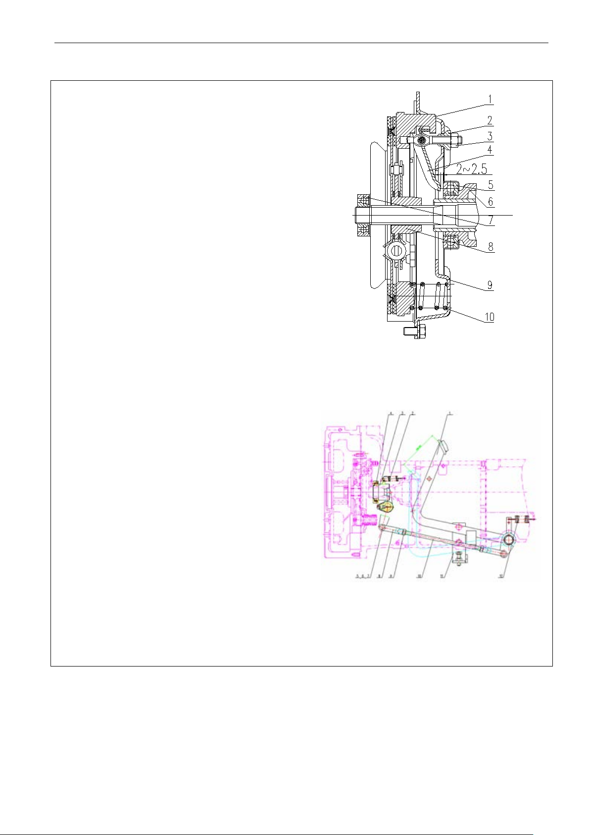
5.2 Clutch adjustment
To ensure the normal work of clutch, the clearance between
face of release lever 6 of
will gradually reduce the clearance until it disappears.
2.5)mm (see the right
Split pin 7. Plain washer; 8. Front fork of lever; 9. Nut; 10.
Maintenance Instructio n
5.2.1 Clutch adjustment (single-acting)
the release lever 4 working face of main clutch and end face
of release bearing 5 should be kept within
(2~2.5)mm. The
clearance between the endauxiliary clutch and release bearing 5 should be kept within
B=(10~11)mm. Continuous wear of clutch friction lining
Therefore check it regularly.
(1) Free travel of clutch pedal is adjusted as follows:
Firstly loosen the lock nut 3 on the release lever (see
fig.5-1). Then rotate the adjusting screw 2 to make sure the
distance between working face of three release levers 4 and
clutch pressure plate 1 shall be (45±0.125)mm, finally lock
with nut 3. Adjust the clutch front fork 4 (see figure 5-2) to
ensure the free travel of clutch pedal is(4-5.5)
the clearance A between working face of release lever 4 and
end face of release bearing 5 is (2figure); after that, lock the nut 5.
(2) Work travel of clutch pedal is adjusted as follows:
Loosen the lock nut 1(see fig.5-2, unit: mm) and rotate the
limit screw 2 to keep the work travel of release rocker arm 3
within (30-35) mm. Finally secure the lock nut 1.
mm, ensure
Fig.5-1 Single-action clutch
1. Pressure plate 2. Adjusting nut; 3. Lock nut 4. Release lever;
5. Release bearing 6. auxiliary bearing seat; 7. Bearing; 8.
Driven plate; 9. Clutch housing; 10. Clutch spring
Fig.5-2 Clutch maneuvering system schematic
1. Pedal pressing; 2. Return spring of thrust bearing seat
3. Releasing bearin g seat; 4. Release bearing; 5. Pin shaft; 6.
Operation lever 11 Pedal check plate; 12. Return spring
54
Page 66
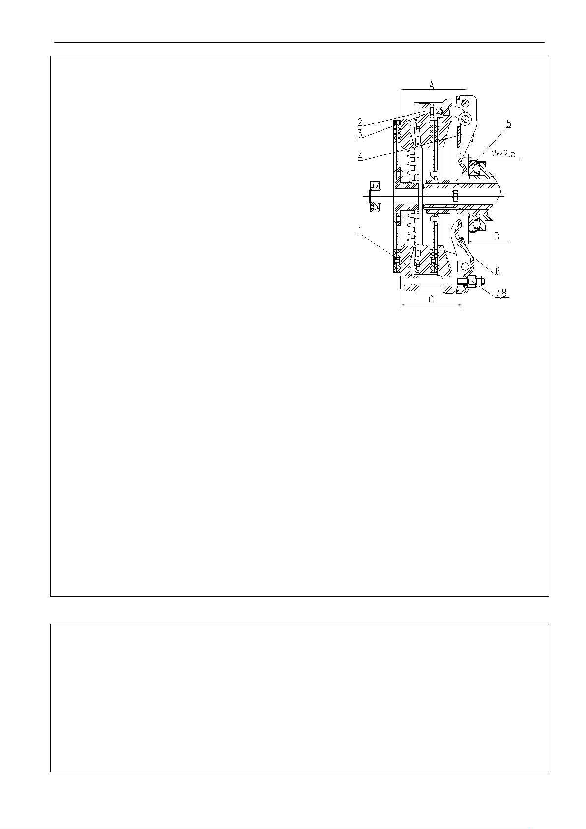
Maintenance Instruction
To ensure the normal work of clutch, the clearance between
face of
release lever 6 of auxiliary clutch and release bearing 5
Continuous wear of clutch friction lining will
Firstly loosen the lock nut 3 on the adjusting screw 2 (see
horsepower type). Finally secure the lock nut3.Firstly
sure the working face distance between auxiliary clutch
release lever 6 and clutch pressure plate 1 should be
2) to
2 to keep the work travel of release rocker arm 3 within
To avoid the oil droplet is contaminated on the friction lining, frequently screw out the drain plug beneath the
If leaking is serious, please
To prevent and avoid the wear of friction lining, the clutch should be frequently maintained and adjusted. Do not
sing the clutch, fast depress the clutch to floor. Never work with
Never work with clutch poorly adjusted. This could accelerate the wear of clutch friction lining and even
5.2.2 Clutch adjustment (double-acting)
the release lever 4 working face of main clutch and end face
of release bearing 5 should be kept within(2~2.5)mm. For
25-28hp model, the clearance between the end-
shall be B=( 10~10.5) mm (10.5-11 mm for 30-32hp
models).
gradually reduce the clearance until it disappears. Therefore
check it regularly.
(1) Free travel of clutch pedal is adjusted as follows:
fig.5-3). Then rotate the adjusting screw 2 to make sure the
working face distance between 3-main clutch release lever 4
and clutch pressure plate 1 should be (86.5
25-28 horsepower type), or A=(101.5+0.2)
loosen the nut7, 8 and rotate the adjusting nut 8 to make
C=(78.5+0.2)mm (for 25-28 horsepower type), or C=
(93+0.2)mm ( for 30-32 horsepower type). Finally secure
the nut 8.Adjust the clutch front fork 4 (see fig.5ensure the free travel of clutch pedal is(20~25)mm. After
that, lock the nut 5 (see fig.5-2).
(2) Work travel of clutch pedal is adjusted as follows:
Loosen the lock nut 1(see fig.5-2) and rotate the limit scre w
±0.2)mm (for
mm ( for 30-32
Fig.5-3 Double-acting Clutch
1. Pressure plate 2. Adjustin g screws 3. Lo ck nut 4. Main clu tch
release lever 5. Release bearin g 6. auxiliary clut ch release lever
7、8. Nut
(40-45) mm. Finally secure the lock nut 1.
Important:
(1)
flywheel housing to drain the dirty oil leaked into the engine and transfer case.
timely troubleshoot. If necessary, use gasoline (or kerosene) to clean the friction lining.
(2)
release and engage the clutch at will. When relea
clutch semi-engaged to avoid damage of clutch.
(3)
burnout.
55
Page 67
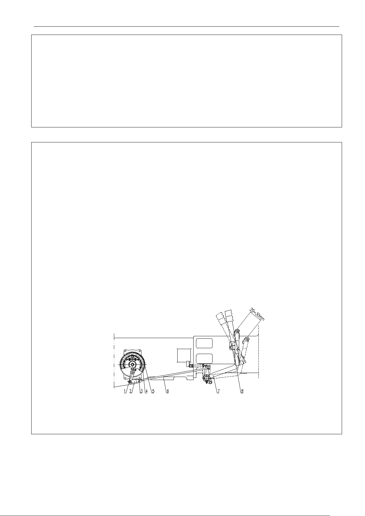
Maintenance Instructio n
(4) When ins talling clutch, fill up the bearing 7(see fig.5-1) and chamber in release bearing block 6 with lithiu m
Do not clean the release bearing by putting it into
change the
length of the brake bar to make the free path (the displacement of the brake pedal from the highest position
emergency braking during the tractor traveling at high speed. At this time, the
base grease. When dismantling the clutch, please check whether the release bearing 5 is lack of lubricant. If so,
put the bearing into heated molybdenum disulfide base grease to let the grease penetrate into bearing. When the
grease cooling down, take it out and carry out installment.
gasoline or diesel to avoid the grease in the bearing is washed away. Otherwise, refill the grease.
5.3. Brake adjustment
5.3.1 If the following items occurs, please adjust it:
Free travel of brake pedal is too large, causing brake fade.
The free travel of brake pedal is too small, causing the semi-brake state as the clearance between the brake
pad and spinning rotor is too small.
The left braking force is not consistence to the right braking force, causing tractor “Offset”.
5.3.2 Brake adjusting method:
Adjustment for free travel of brake pedal
Loosen lock nut 3 on brake bar 6, remove the sp lit pin on the brake bar, rotate brake bar to
to the position where the gap between the brake hub 5 and the brake shoe friction plate 4 disappears) of the
brake pedal within (20~30) mm, and make the lengths of the left and right brake bars 6 be same, then use
lock nut 3 to lock tightly. Then lock short link with lock nut 3.
Brake “Defection” adjustment
If the adjustment of left and rig ht brakes is not consistent, the left a nd right tire traces will not consis tent
(Viz “Deflection”) when
brake link with short trace should be properly shortened or the brake link with long trace should be properly
extended until the traces are similar and braking is reliable. Then lock the nut3.
Fig. 5-4 Braking system
1. Rocker arm 2. Adjusting fork 3.Lock nut 4. Friction lining 5. Brake drum; 6. Brake rod
7. Brake pad 8.lock plate of brake
56
Page 68
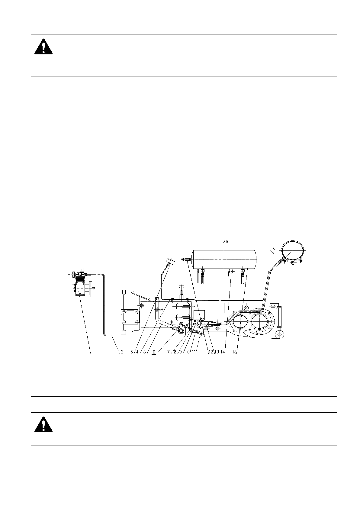
Maintenance Instruction
The free travels should be the same for left and right brake pedals. Otherwise, in case of
Generally, the balance pressure in the air reservoir should not be less than 0.70MPa.Otherwise, please adjust the
air pressure regulator. When engine is stopped, if air pressure alarm gives the warning, it indicates there is any
Opening pressure of air reservoir relief valve is (0.75~0.8)MPa. Please timely adjust and demarcate the air
synchronizing with tractor braking or is slightly in advance rather than lag behind.The adjusting method is as
Extend the adjusting link 8 to lag behind the trailer brake time.If necessary, this can be done by adjusting the
. Outlet pipeline of compressor 3. Air pressure warning 4. Connection to barometer 5. Brake pedal 6. Short rocker
the trailer braking should be consistent with tractor braking or be slightly in advance. Otherwise,
Caution:
emergency braking, the tractor will sharply deflect to one side, causing possible accidents.
5.4 Trailer air brake adjustment
(1) If the tractor transporting with trailer, the system pressure should not be less than 0.44MPa.Otherwise, you are
allowed to drive the tractor only raising the air pressure to set value.
(2)
leakage and troubleshoot.
(3)
pressure during work.
(4) If the air pressure is always within (0.75~0.8)MPa or more, it indicates the relief valve will not relieve the
pressure. Please timely clean or replace the relief valve.
(5) After daily work is over, open the drain valve 14 to drain the deposited water in the air reservoir 15.
(6) If the tractor transporting with trailer, please check the whole braking system to ensure the trailer braking is
follows:.
Loosen the nut 10 and rotate the adjusting fork 11 to shorten the adjusting link 8 to bring forward the trailer braking
time.
screw 7, then secure the lock nut 9,10.
Fig. 5-5 Trailer air brake system
1. Air compressor 2
arm 7. Adjusting screw 8. Adjusting link 9. Lock nut 10. Nut 11. Adjusting fork 12. Relief valve 13. Air brake valve 14. Drain valve 15.
Air reservoir
Caution:
the roller accident will occur.
5.5. Main drive adjustment
57
Page 69
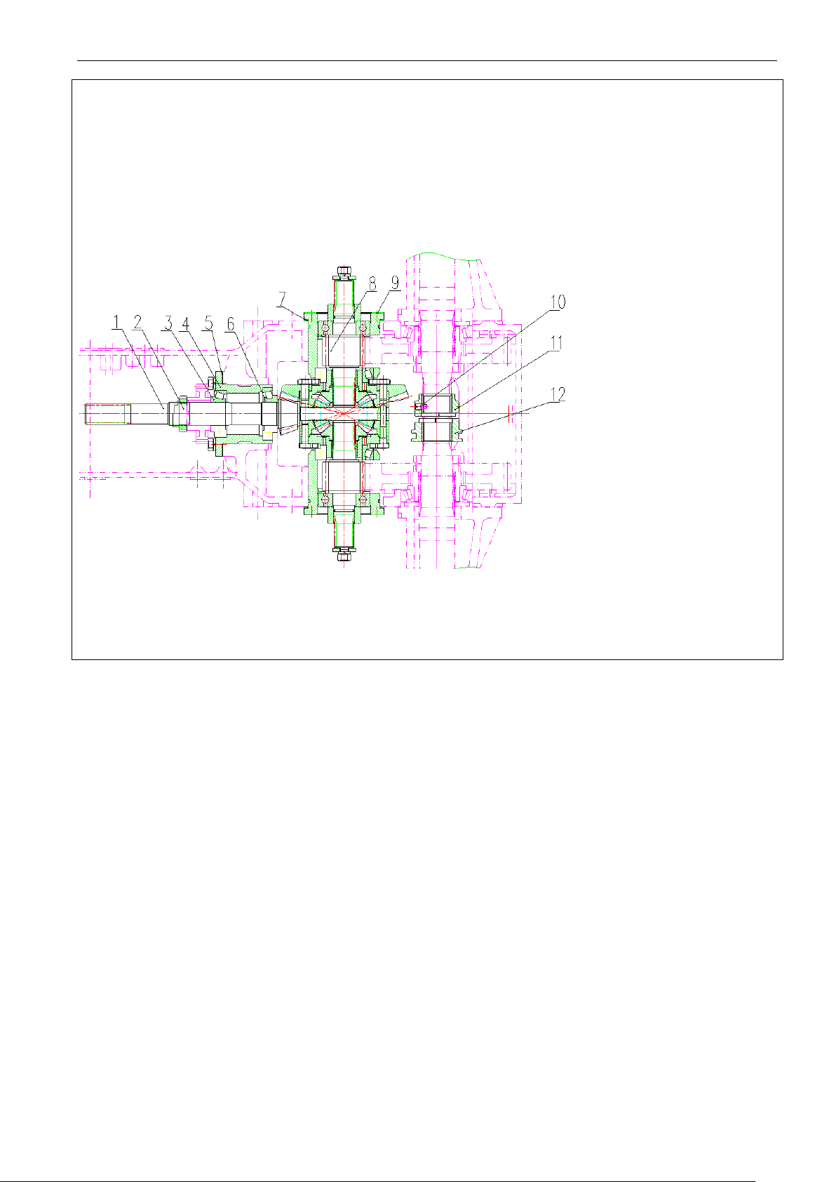
Maintenance Instructio n
After use for a while, the bearing wear will gradually eliminate the preload, creating the play between the two
1. Driving bevel gear of main drive; 2. Lock nut; 3. Cone bearing; 4. Bearing seat of driving gear; 5. Adjusting
. Paper pad; 10. Screw; 11. Right jaw;
5.5.1 Tapered bearing preload adjustment (see Fig. 5-6)
bearings. If the play is more than 0.1mm, the tapered bearing should be pre-tightened again.
The preload adjustment of 2nd shaft tapered bearing:
Adjust the lock nut 2 close to the bearing 2 to adjust the torque of driving bevel gear 1 to (1.5~2.5)N·m. Lock the nut
2 after the adjustment. If it is difficult to measure the torque, ask skillful person for help. The nut shall be locked after
the adjustment.
Fig.5-6 Tapered bearing preload adjustment
washer; 6. Cone bearing; 7. Adjusting washer; 8. Short axle shaft assembly; 9
12. Left jaw
58
Page 70

Maintenance Instruction
The meshing mark and backlash should be adjusted and then checked regularly when the wear is excessive, meshing
Install same number of adjusting washers (No. 5 and No. 7) between the bearing seats of the two sides of differential
al in order to increase the torque of driving bevel
; install proper number of washers (No.5) out of the bearing seat and
and correct contact pattern (the pattern shall be in the
During adjusting, the axial motion of bevel gear and bevel pinion will change the meshing mark and backlash. If the
requirements for the meshing mark contradict with that for backlash, the meshing mark should prevail. Yet the
During the normal work of tractor, it is not needed to adjust as long as the meshing mark is normal.The adjustment
done when overhauling tractor or replacing a pair new of main drive gears or bearings.
5.5.2 Adjustment of meshing mark and backlash of bevel gear pair.
mark is abnormal (that could give impact or noise) or replacing with new tapered gear pair.
and the case to adjust the pre-tension of cone bearing of differenti
gear (No.1) of main drive by (0.4~0.7)N·m
change the left washers with the right washers of bearing seat of the differential to change the engagement of spiral
bevel gears to make the normal backlash to reach 0.15~0.25
middle of working teeth and close to the toe; spot patterns are allowed; however, the length shall be not less than 60%
of teeth length and height not less than 50% of teeth height)
For the adjusting method of backlash and meshing mark, please see table 5-2.
adjusting range of backlash should be widened, especially carry out adjustment after wear or gear and bearing. The
backlash should not less than 0.1mm
should be carefully
Meanwhile the meshing mark and backlash should be right.
Important: the bevel gear and bevel pinion of main drive are a pair of gears. Do not reversely install them. The
gears should be replaced in pair. It is better to be replaced with bearing, otherwise the tractor life will be shorted.
59
Page 71
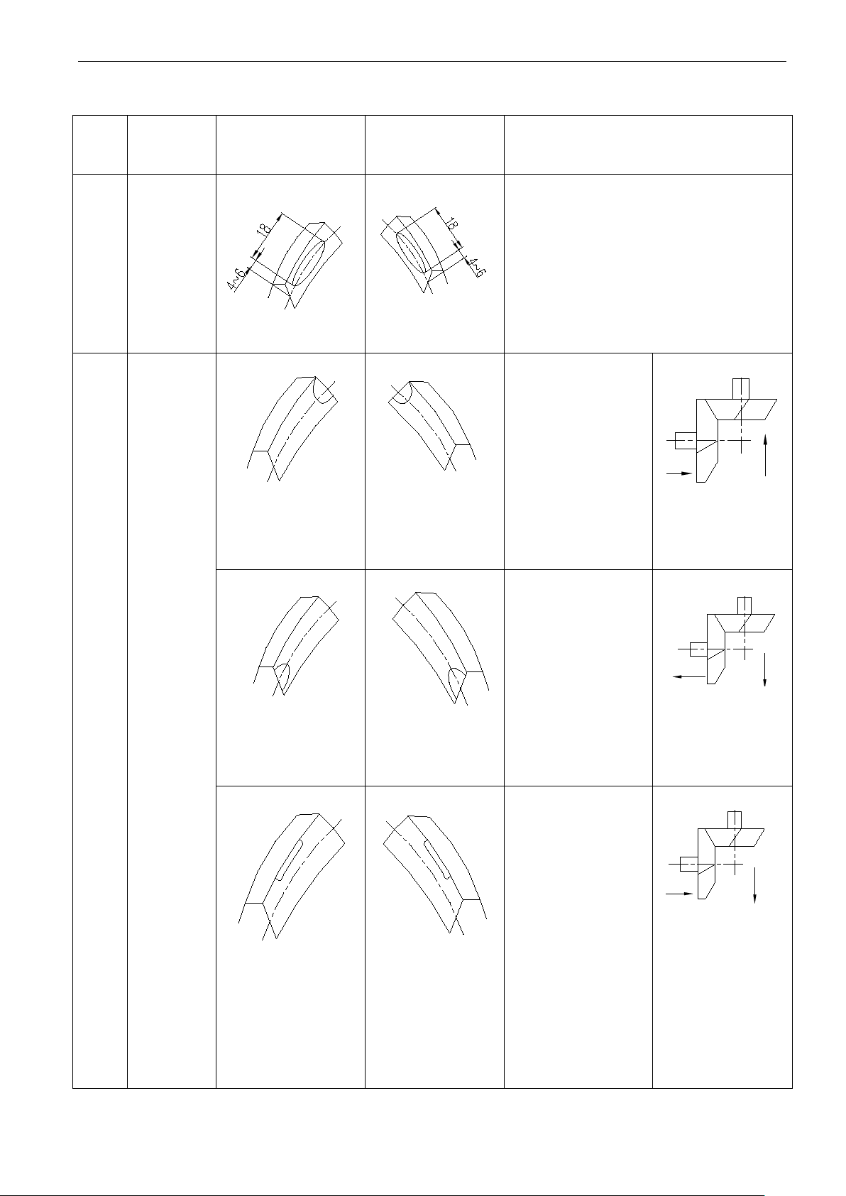
Maintenance Instructio n
If engaging forward gear, the meshing mark
should be less than 60% of tooth width, and
n 50% of
tooth height. The mark should be allocated
If engaging reverse gear,
the meshing mark on the convex face on the
spiral bevel pinion should be same as the
Increasing the
adjusting shim
on the front
bearing bushing
could move the
bevel pinion
If the clearance
is large, please
move the bevel
Decreasing the
adjusting shim
bearing bushing
could move the
bevel pinion
If the clearance
is small, please
move the bevel
Decreasing the
adjusting shim
on the front
bearing bushing
could move the
Removing the
adjusting shim
on the left
bearing bushing
to the right
bearing bushing
could move the
Table 5-2 Adjustment for spiral bevel pinion of main drive
Index:
1
Description
Normal
mashing
mark
Bevel pinion meshing
mark(forward gear)
Bevel pinion
meshing
mark(reserve gear)
Adjusting instruction and diagram
length on concave face of spiral bevel pinion
its height should not be less tha
around the center of tooth height and slightly
near the tooth toe.
above said.
(1)
of the 2nd shaft
forward.
(2)
Abnormal
2
meshing
mark
(1)
(2)
(1)
(2)
gear to the right.
on the front
of the 2nd shaft
backward.
gear to the left.
of the 2nd shaft
bevel pinion
backward.
bevel pinion to
the right.
60
Page 72
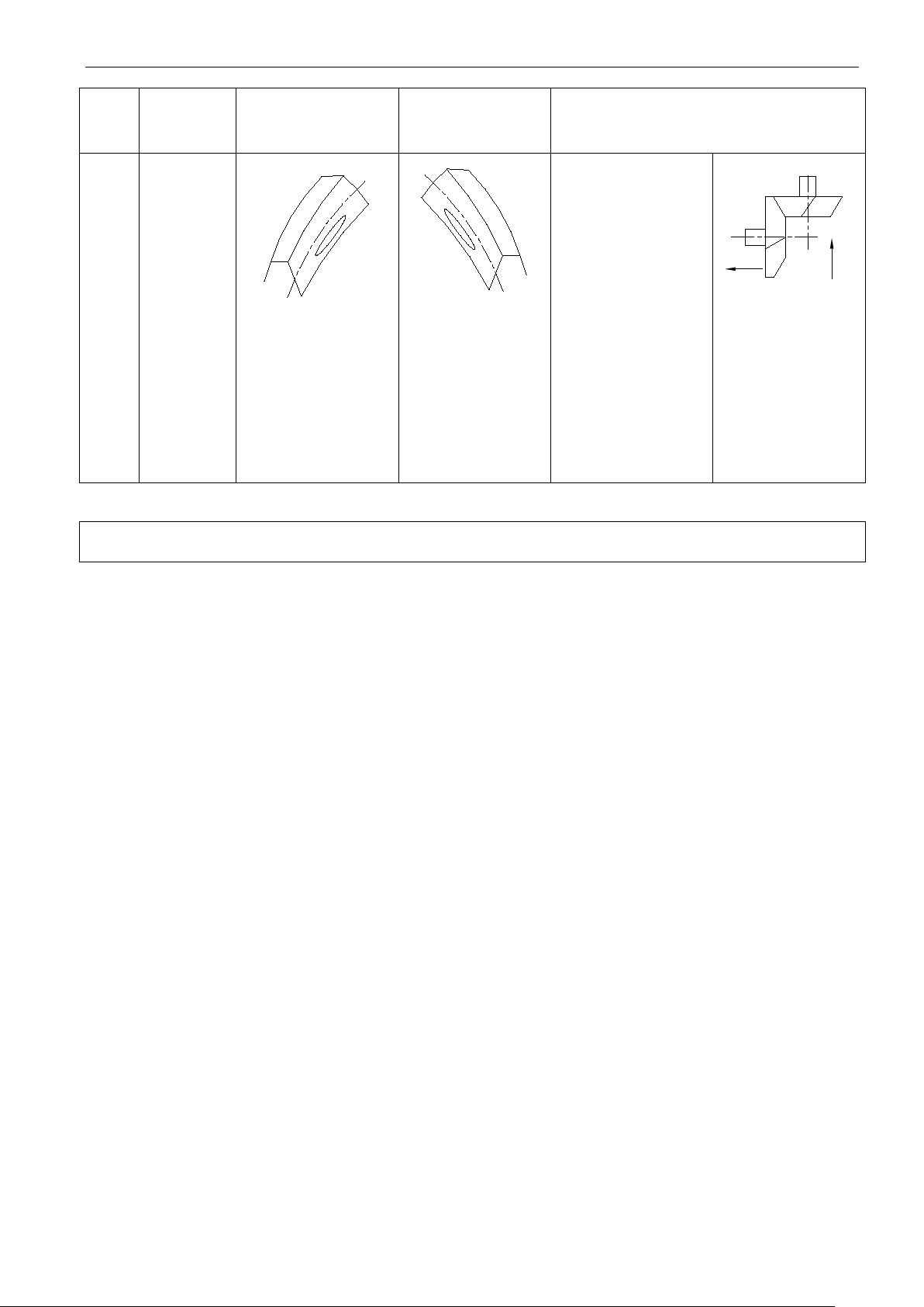
Maintenance Instruction
Increasing the
adjusting shim
on the front
bearing bushing
could move the
l pinion
Removing the
adjusting shim
on the right
bearing bushing
to the left
bearing bushing
could move the
bevel pinion to
Bevel pinion
meshing
mark(reserve gear)
Index: Description
Bevel pinion meshing
mark(forward gear)
(1)
Note: The straight arrow shows the gear moving direction.
Adjusting instruction and diagram
of the 2nd shaft
beve
forward.
(2)
the left.
61
Page 73
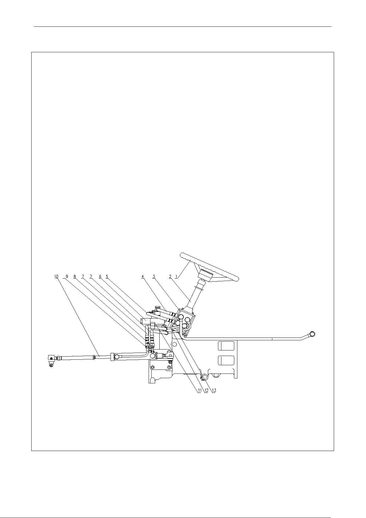
Maintenance Instructio n
hydraulic steering, as shown in figure.Before delivery, the steering
hydraulic steering
ilure, please firstly find out the cause. Do not forcefully rotate the
steering wheel. Never dismantle steering gear to avoid damage of parts.Never rotate the steering wheel by
After changing oil, please vacuum the cylinder.Air bleeding method: loosen the steering cylinder bolt to
steering cylinder piston rod and steering wheel. Rotate the steering wheel to let the piston at the leftmost or
rts and not allowed to be dismantled without permission. If
nsition pipe of cylinder; 9.
5.6 Adjustment of traveling and steering system
5.6.1 Precaution for full hydraulic steering system
LOVOL series 4-wheel drivetractor adopts fullsystem is already adjusted.Please take note the following items during operation.
Frequently check the each threaded connection and tighten it if necessary.When full-
system is working, there should be no leakage at each connection.
During operation, if steering is heavy or fa
two persons.
When installing full-hydraulic steering system, steering gear and steering shaft should be at the same axial
line with clearance at axial direction.After installation, check the steering wheel for flexible rotating.
Keep the oil clean.Therefore frequently check the filter element and oil level.Inspection method: drop an oil
droplet on the blotter. If there is a black center on the blotter, change the oil.
bleed air with oil pump at low speed until there is no bubble emerged in oil.Disconnect the link between the
rightmost (do not stay at the both extreme positions).
A flow dividing valve is of sophisticated pa
removing it, please use clean gasoline or kerosene at clean site.
Before delivery, the flow dividing valve is already adjusted. Do not remove and adjust it by yourself.
Fig.5-7 Full hydraulic steering system
1. Steering wheel assembly; 2. Steerin g column assembly; 3. Hydraulic st eering gear; 4. Diverter valve oil return line; 5. Oil inlet
pipe of steering gear; 6. Stable splite-flow valve o f single line; 7. Oil cylinder hose assembly; 8. Left tra
Right transition pipe of cylinder; 10 Drag link and steering cylinder assembly; 11. Welded bracket of splite-flow valve; 12. Right pipe
of cylinder; 13. Left pipe of cylinder
61
Page 74
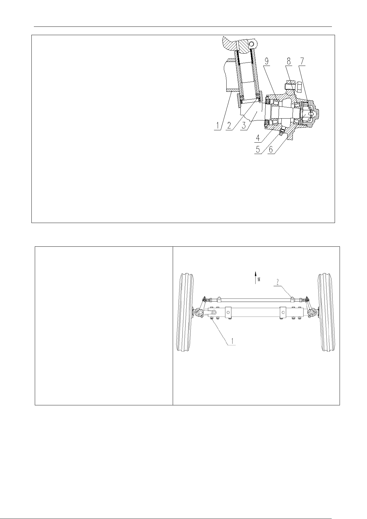
Maintenance Instructio n
front shaft with a jack, remove
bolt 1 for left/right inner/outer sleeve and
then remove connecting bolt 2 on tie rod.
Adjust left/right inner sleeve position and
wheel tread are 1100mm, 1200mm and
5.6.2 Front drive axle main drive adjustment
Normal axial clearance between front wheel bearings 8 and 9 is
0.05~0.15mm. During the operation, if the clearance is greater
than 0.4mm, the front wheel of the tractor will mo ve from side to
side and the bearing may be damaged by the impact. Therefore, it
is necessary to adjust the clearance immediately. When adjusting,
prop up the front wheel above the ground, remove bearing cap
and pull out split pin 7 of nut 6. Screw nut 6 until the clearance
disappears, return nut 6 by 1/15~1/7 circle, then lock nut 6 with
split pin 7 and install bearing cap.
Figure 5-8 Front Wheel Hub
1. Front Shaft Bushing 2. Thrust Bearing 3. Steering Knuckle
5.6.3 Adjustment for Front Wheel Tread
Adjustment for two-wheel driven tractor:
prop up the
left/right tie rod length. Finally, install bolts
and lock the removed bolts. Three options for
1300mm.
4. Front Wheel Hub 5. Oil Cup 6. Nut 7. Split Pin
8. Bearing 9. Bearing
Figure 5-10 Front Wheel T re ad Adjustm ent
Narrow 1050mm wheel tread is optional;
62
Page 75
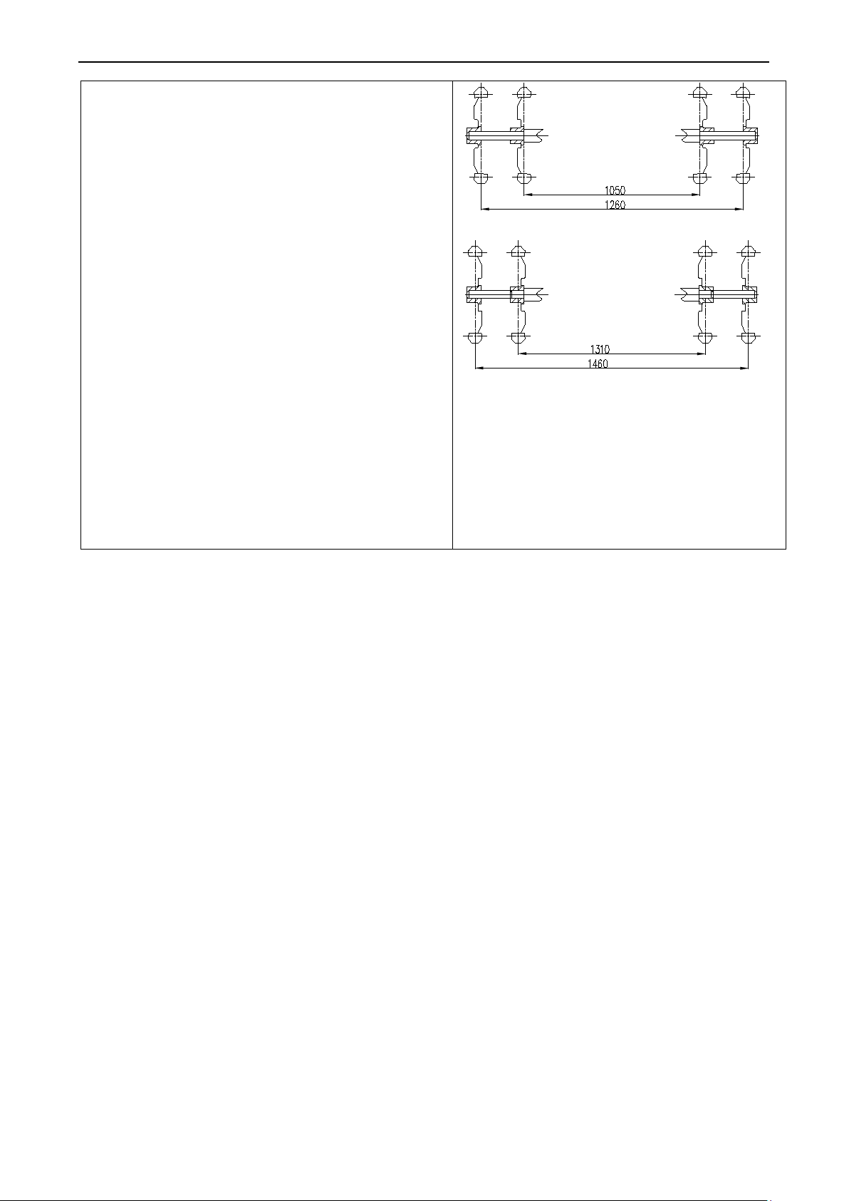
Maintenance Instructio n
ear wheels is achieved by
changing fixed position of rear wheel hub on driving
by turning drive wheel rim over and exchanging
For the second rim installation type, adjustment range of
28hp tractor can select 960mm narrow
5.6.4 Adjustment for Rear Wheel T r ead
Stepless adjustment for r
shaft. At the same time, step adjustment can be made
left/right drive wheel.
For the first rim installation t ype, a dju stment ran ge of tread
is 1050~1260mm.
tread is 1310~1460mm.
TE series 25-
tread;
TE series 30-32hp tractor can select 1000mm narrow
tread.
5.7. Adjustment of front drive axle
Figure 5-11 Adjustment of Rear Wheel T read
63
Page 76
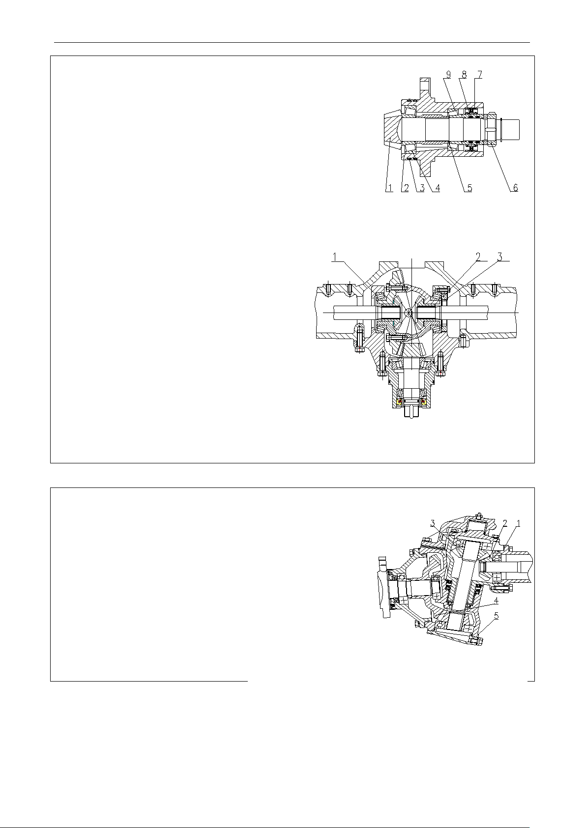
Maintenance Instructio n
Fig.5-14Front drive axle side drive adjustment
Fig.5-13 Differential housing bearing adjustment
Fig.5-14Front drive ax le main drive a djustment
5.Adjusting shim 6. Nut 7.Oil sealing 8. O-ring 9. Bearing
5.7.1 Front drive axle main drive adjustment
The 2 tapered roller bearings respectively on the front drive bevel
pinion shaft and on the right and left of differential housings are all
preload. Any wear of bearing could create axial play at the bevel
pinion and differential housing. Accordingly check them periodically
every 1600h.The bearing of bevel pinion is adjusted through
thickness of adjusting thim to torque the bevel pinion shaft to(0.7~
1.0)N·m. Then lock the nut6.
The bearing of differential housing can be adjusted
as follows: select a proper adjusting shim1, tighten
the adjusting nut 2 and retainer mat3. If the rotating
torque is greater than that without differential by
(1.4~1.7)N·m, the preload amount is proper.At
this time, there will be no motion if pushing the
bevel gear along with axial line.
The testing method of backlash and meshing mark is
the same as that of rear axle main drive.
1.Driving bevel pinion shaft 2.Bearing block, driving bevel pinion 3.
O-ring 4. Bearing
1. Adusting shim 2. Adjusting nut 3. Retainer mat
5.7.2 Front drive axle side drive adjustment
Stage I intermediate drive meshing mark and backlash of between driving
gear and driven gear can be adjusted by adjusting shim1; StageII final
drive meshing mark and backlash of between the driving gear and driven
gear can be adjusted by adjusting shim5.The backlash at both locations is
required as (0.25~0.45)mm.
1. Adjusting shim 2.Intermediate drive driving gear 3.Intermediate
drive driven gear 4.Final decelerat ion driven gear 5.Adjusting shim
64
Page 77
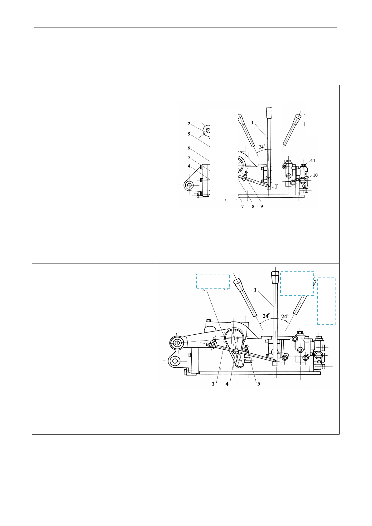
Maintenance Instructio n
Adjustment of agricultutral
lifting direction to make the distance
mm, then lock block 6 on thrust rod 8
Outer lifting arm; 3. Inner lifting arm; 4. Check pin; 5.
Adjustment of agricultutral
n the cylinder is
pushed near bottom dead center). Then
N
Droping
Hoisting
5.8 Hydraulic lifter adjustment
Place the control lever for agricultural implement lifting and lowering to the neutral position. This ends by
adjusting the distance between the stop on the adjusting link and stop pin fixed on the lifting shaft.
5.8.1
implement max. position
Firstly rotate the outer lifting arm2 to the
between the lower end of inner lifting arm 3
and check pin 4 on the rear cover of lifter be
5mm (insert a 5mm block in air plug 5).
Make sure the distance between the inside
the check block 6 and check pin 7 be (9
10)
with the bolt and lock the bolt with nut.
5.8.2
implement min. position
Firstly rotate the outer lifting arm 2 along
with lowering direction to min. position (at
this time, the piston i
make sure the distance between the stop 5
and stop pin 4 on the link3 should be (9~
10)mm.Then use the bolt on the stop4 to
lock it on the link.
~
eutrality
Fig.5-15 Adjustment for lifting position
1. Control handle 2.
Air plug; 6. Check block; 7. Check pin; 8. Thrust rod ; 9. Drop check bloc k;
10. Hydraulic output plug; 11. .Adjustin g va lve
Hoisting
Neutrali
ty
Dr
op
pi
ng
Fig.5-16 Adjustment for descending position
1. Control handle 2. O uter lifting arm ; 3. Thrust rod; 4. Check pin;
5. Drop check block;
65
Page 78

Maintenance Instructio n
Special maintenance is unnecessary. Observe the
the battery is low;
the battery is extremely low; In case of Black,
rged; in case of White, the
5.9 Maintenance of battery
● Maintenance of service-free battery
inspection hole of electrolyte hydrometer: Green—the
battery is well charged; BlackWhitethe battery shall be cha
battery shall be changed.
Figure 5-17 Inspection of battery
Warning
The battery electrolyte is corrosive. If it splashes on eyes or clothes, wash with clean water at once and come to
the doctor; otherwise it may cause serious injury.
66
Page 79

Maintenance Instructio n
with good
8. Always check the air hole of battery during the operation or storage of battery to avoid deformation or
2 hours, it means the charging is done (voltage difference less than 0.03V)
Positive pole and negative pole of battery shall be connected with the positive pole and negative pole of
during charging. If the temperature is high, use water or decrease the
The engine life is directly dependent on the correct use of air cleaner to keep it clean
ways.During field working, please check, clean and then change oil each shift.If the tractor is equipped with
● Precautions of operation and maintenance of battery
1. The battery shall be kept in dry and clean environment where the temperature is 5~40℃
ventilation.
2. The battery shall be protected away from sunlight and be at least 2m away from heat (heater).
3. The battery shall be protected against rain, dust and foreign matters as well as shirt circuit.
4. The battery shall be not be horizontally or reversed placed and be protected against mechanical impact or great
pressure.
5. The battery shall be fully charged before storage; Low battery is not allowed for storage.
6. The battery shall not be inclined, revered or knocked.
7. Check the voltage every three months. If the voltage is below 12.5V, charge the battery; otherwise it affects the
battery service life.
explosion.
9. Good ventilation shall be ensured during charge and discharge of the battery; otherwise the acid mist and
flammable gas produced during the charge may hurt the operator and equipment and even cause fire.
10. Always check the color of power densimeter on the battery cover and take proper actions in accordance with
the color.
● Way of charging
The battery can be charged at constant current or constant voltage with limited current. For service-free battery,
the constant voltage with limited current is preferred.
1.Charging at constant current
Charge the battery at 0.1C
A (12 A) current to 16V and then charge at 0.05C20A (6A) current. When the battery
20
voltage remains unchanged for 13V); or charge the battery to 16V and then charge at 6A current for 3-5 hours.
2. Charging at constant voltage with limited current
Constant voltage 14.8V~15.5V, maximum current 0.25C
A, namely 30 A; if the current is ≤0.5A, charge the
20
battery for 3 hours; total charging hours shall be not longer than 24.
● Precautions during charging
1.
charger respectively.
2.The battery shall be horizontally placed and the wire shall be securely connected.
3.The battery shall be not above 45℃
current or voltage to reduce the temperature.
4.The charge room shall ensure good ventilation, because it produces flammable hydrogen. If there is 4%--7%
hydrogen in the air, it may cause explosion. Smoking is prohibited in the charge room.
5.Short circuit is not allowed when connecting the wires to charge the battery.
Importance:
al
harvester, it is better to use higher grade of filter.Never use the oil-water to flush dry-type filter element during
maintenance.
5.10 Fan belt tension adjustment
67
Page 80
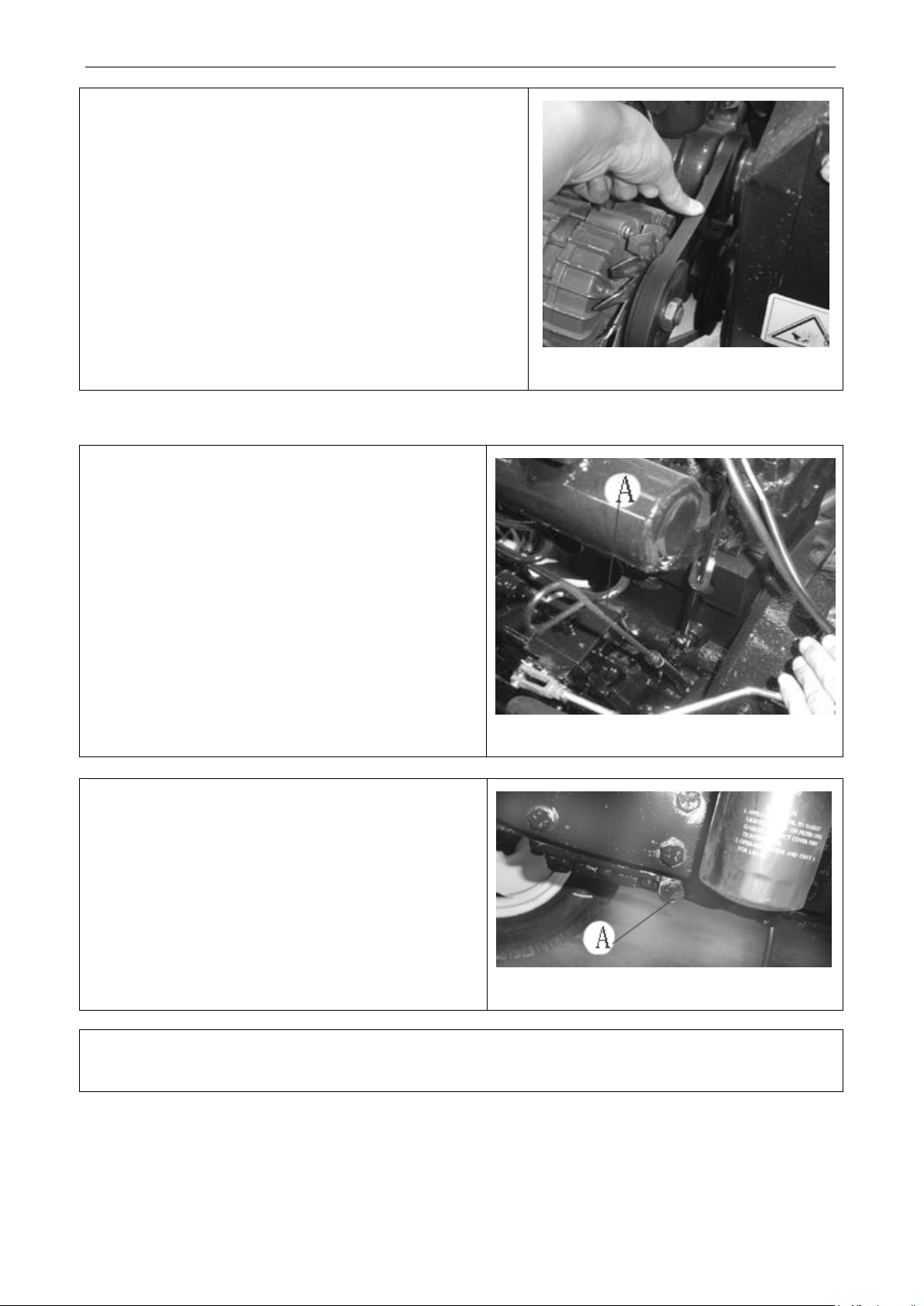
Maintenance Instructio n
Use finger to press around the center of belt span by the applied
outward to tension the belt and then tighten the fixing nut on the
ump to check whether the oil level is between
upper and lower scales.If oil lever is not at lower
Screw out the drain plug A on the bottom of oil sump to
il and never mix the different grade oil to avoid damage of
force of (29.4~49.0)N. The pressed distance should be (15±3)mm.
If not, please adjust it as the following method:
Loosen the fixing nut on the generator adjusting frame. Push it
generator bracket.
5.11 Check and change oil in the engine oil sump
(1) Pull out th e dipstick A on the left-front zone of engine
oil s
Fig.5-18 Adjustment of fan belt tension
scale, please fill oil to regulated level.
(2)Before changing oil and maintenance, please preheat the
engine unitle the oil temperature is up to 50℃~
drain the used oil and clean the sump. Then fill the new oil.
60℃.
Fig.5-19 Oil level inspection in the engine oil sump
Important: never mix the new and used o
engine.Change oil strictly in accordance with Diesel Engine Instruction.
Fig.5-20Oil change in the engine oil sump
68
Page 81
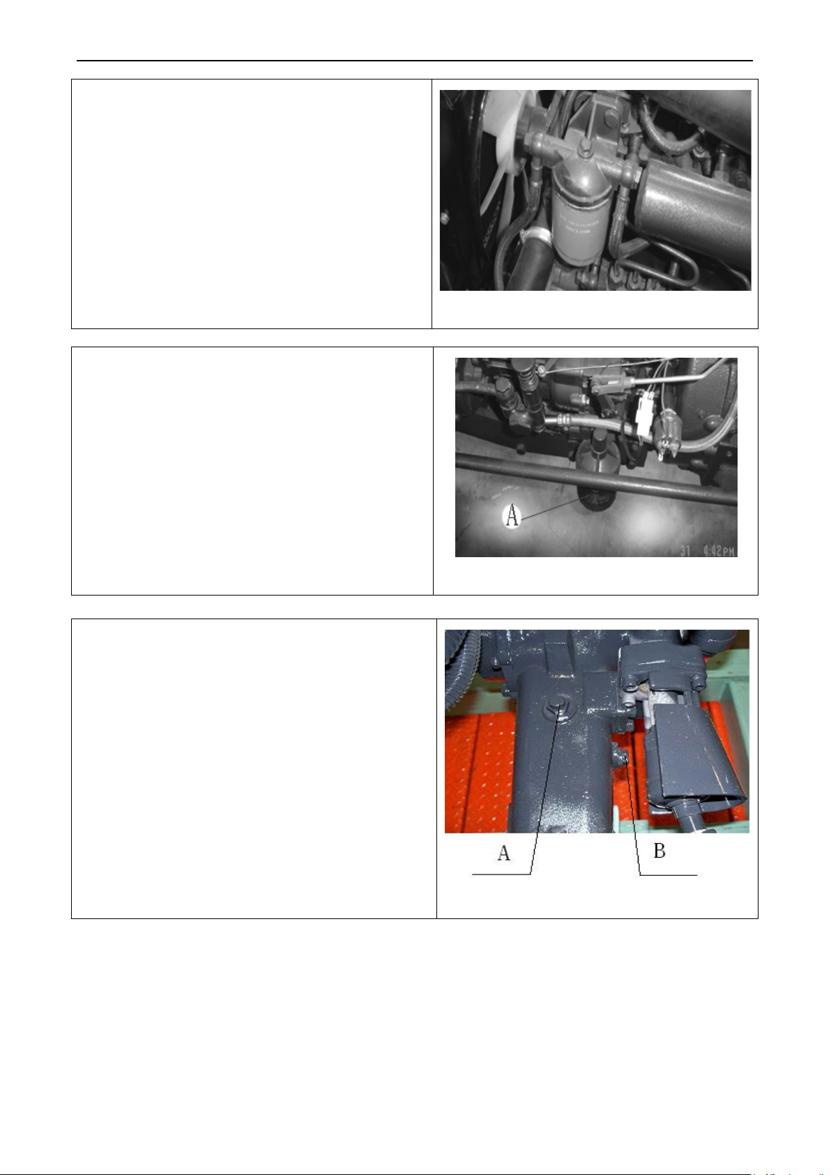
Maintenance Instructio n
Fuel filter is located on the left front side of engine.Paper
filter element every 200h.For detail maintenance, please
lower side of engine.
lace it every 200h according to technical
requirement.Please entirely replace the oil filter. Secure it
When checking for oil level in the front drive housing,
please remove the dipstick “A” to ensure the oil lever is
and right to drain the used oil. Tighten the plug again. The
oil should be filled from “A”. After a while, oil
5.12 Fuel filter maintenance
filter element of filter is not allowed to clean.Replace the
follow the manufacturer’s instruction.
5.13 Oil filter maintenance
Oil filter A is located at the leftRep
during installing.For detail maintenance, please follow the
manufacturer’s instruction.
Fig.5-21Fuel filter maintenance
5.14 Oil level inspection of front drive axle
within scale range. If not, fill oil.When changing oil, screw
out the drain plugs at main drive and final drives at the left
overflowing from B shows that the oil is filled up.
Fig.5-22 Oil filter maintenance
Fig.5-23 Oil level inspection of front drive
69
Page 82
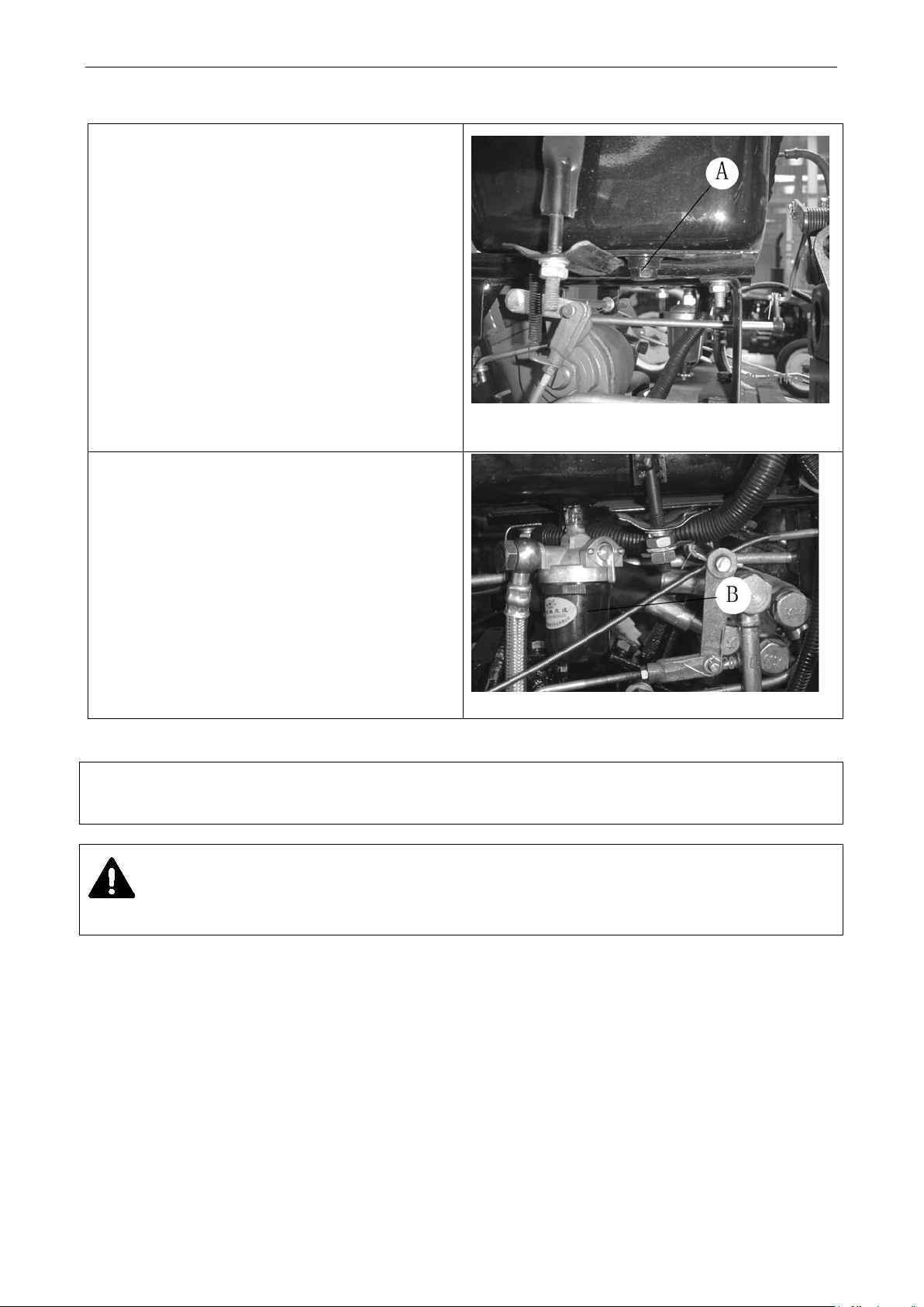
Maintenance Instructio n
on the
Fuel tank sediment cup has functions of water
ediments in
Figure 5-25 Fuel Tank Sediment Cup
5.15 Fuel tank maintenance
Park the tractor on the flat ground. Shut down the
engine. Then remove the drain plug A
bottom of fuel tank to drain the deposition in fuel
tank.
and impurity sedimentation. S
sediment cup B at the bottom of fuel tank shall be
discharged during maintenance.
5.16 Tire pressure inspection
Use barometer to check the tire pressure that should meet the TE Series Tractor Operation Manual 8 Technical
Specification.
Fig.5-24 Fuel tank maintenance
Caution: The excessive high/low tire pressure will shorten the tire life, causing harmful effect on tractor
traveling and maneuvering.
5.17 Engine cooling system maintenance
70
Page 83
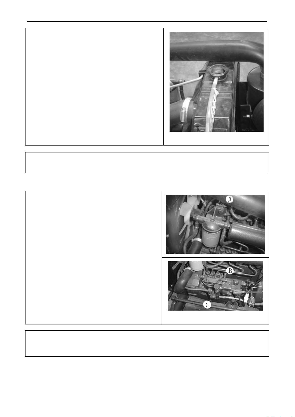
Maintenance Instructio n
The engine coolant can be from boiled tap water or be
antifreezeValid duration of antifreeze is two years or 1600h. if
caustic soda and 150g kerosene in the 10L water,
10min and shut it down. Keep the
intermediate speed for 20min. Stop it to drain the solution.
When the engine cools down, insert a water pipe into the
the bottom of radiator.After that, close the drain valve and fill
water. Keep the engine running for 20min and drain water
again.After engine cooling down, fill the new antifreeze or
he air may enter fuel pipe if tractor is out of use for long
time, replacing diesel filter element or emptying the fuel
engine. Vaccum the fuel sytem when the fuel tank is filled up
Loosen the bleed screw A on the fuel filter. Move the fuel
screw on the fuel injection pump. Finally move the
on the fuel delivery pump upward and
downward until the diesel is overflowed from the bleed
light diesel for winter.The diesel should be clean and deposited for at least 48h before use. Otherwise, it will
exceeding, change the antifreeze, flush the cooling system and
fill the new antifreeze.The removing of scale in cooling sytem:
add 750
then fill the mix into cooling sytem.Let the engine rotate at
intermediate speed for 5solution stay for 10-12h (note: carry out thermal insulation for
winter to avoid freezing). Restart the engine a nd let it rotate at
radiator to flush it. At this time, please open the drain valve on
g
cooling water to specification.
Fig.5-26 Engine cooling system maint enance
Important: in winter, as to the tractor without use of antifreeze, drain the water with engine idling if water
temperature is below 70℃, preventing the cooling water freezing related parts.
5.18 Fuel system venting
T
tank.The air in the fuel system will lead to difficult start of
and oil pipeline switch is turned on.
delivery pump handle B upward and dowmward until the
diesel is overflowed from the bleed screw without bubble
emerged.
Tighten the bleed screw A again and loosen the bleed
handle B
screw without bubble emerged. The the bleed screw C
should be tightened.
Fig. 5-27 Fuel sytem venting
Important: engine must employ qualified light diesel. Generally, use 0# light diesel for summer and use -10#
shorten the engine life.
71
Page 84

6 Storage
term shutdown, it is more necessary to have a scientific storage and special
during shutdown period, dusts and water vapor in the air diffuse into machine
by the cracks, holes, etc. to make the parts to be contaminated and corroded; the relative motion surfaces, such
s, bearings, gears, etc., will lose mobility and pressure protection from lubricant films after
they have been in a stationary state for a long time, thus to produce corrosion, rust, cementation obstruction or
Aging: The rubber, if bathed in sunshine, the rubber, plastic and other parts will be easy to aging,
Drain antifreeze and antirust liquid in the heat radiator, cylinder and water pump, and drain the lubricant from
Remove the battery and the lubricating grease and store them in a dark and ventilated room at a temperature
Loosen fan belt on the engine or remove it when necessary, and wrap it up and store it separately. T hen spray
Use protective material (such as canvas, waterproof cloth and oil paper) to seal up the pipe ends of engine,
After the tractor has completed stage work, or for some reasons, needs to be stopped for a lone time (more than one
month), it shall be properly kept or sealed for safekeeping to prevent mechanical parts from corrosion, aging and
distortion.
To seal up the tractor for safekeeping, the first step is to clean the tractor thoroughly, adjust and tighten all connecting
pieces, then complete required technical maintenances in working hours to make the tractor in good technical state.
Important: During period of longmaintenance for the tractor. Otherwise, the technical deterioration time of tractor will be faster than working period.
6.1 The reasons of tractor damage in shutdown period
6.1.1 Corrosion and contamination:
as pistons, valve
stagnation, so scrapped.
6.1.2
deteriorating, become brittle so as to lose activation, or to be corroded.
6.1.3 Distortion: If pressed for a long time, the parts such as drive belt and tire might appear plastics distortion.
6.1.4 Others: The electric components are caused self-discharge.
6.2 Storage of tractor
6.2.1 Prior to stora ge, check the tractor care fully, and eliminate all existing failures to maintain it in good technical
conditions. Then clean up external surface of tractor.
6.2.2
power train and hydraulic oil from hydraulic system to let them run out until empty.
6.2.3
higher than 10℃.
6.2.4 Drain th e oil out of en gine while it is hot, ref ill new oil, and allow s mall throttle running for several minutes,
6.2.5 Apply the lubricating grease on all lubricating points.
6.2.6 Heat dehydration Vaseline up to 100~200℃, and apply it on the contacts, connectors of electric components
6.2.7
so that the oil can evenly attach to the surface of all moving parts.
and on the surface of metal parts unpainted.
antirust agent in the pulley slot. Repair the paint where the paint has fallen off on the tractor.
6.2.8 Drain and clean the diesel tank.
6.2.9
6.2.10 Pla ce all the control sticks in neutral po sition (including electric system switc h) with the front wheel in right
6.2.11 Use wooden frame to support the tractor, in order to release the loads on the front wheel. And regularly check
such as inlet, outlet, to eliminate the entry of foreign substances, dusts and water.
direction and suspension rods in lower position.
the tire pressure.
70
Page 85

Storage
6.2.12 The tractor shall be parked in a hangar or car shed with ventilated and dry air. Prohibit to be put them with
ose the dry platform in
Clean up all the parts and provided tools removed from the tractor and wrap them up carefully, then store
g and distortion, etc., if any,
Rotate engine crankshaft for 10~15 turns every 2 months to prevent internal parts from corrosion. Remove the
If the user doesn’t have the conditions for antirust disposal, and the tractor needs to be shutdown for
start it once every 2 months, then check all parts for
30 min at idle speed. While keep the surface of tractor clean, dry to prevent
st drive belt tension according to technical
corrosive substances and gas together. If the conditions are not met, you must cho
higher ground for storage when parking in open places, and to cover it with tarpaulin.
6.2.13
them in a warehouse with dry air.
6.3 Maintenance during period of sealing-up for safekeeping tractor
6.3.1 During sealing-up period for safekeeping tractor, all the above requirements must be met.
6.3.2 Check once every a month to see if the tractor and parts appear corrosion, agin
take actions for troubleshooting immediately.
6.3.3
old lubricating grease where the parts need to refilled and put new lubricating grease.
6.3.4 Start tractor to d rive for 2 0-30 minutes once every 3 months, and check all the parts for exception functions at
idle speed.
6.3.5 Use a dry cloth wipe up the top surface of battery regularly,. T he battery will be self-discharged, even during
unused period. It shall be recharged once every month.
Important:
several months or more, replace oil, oil filter at least, and
abnormal functions when driving 20machine parts from damage due to corrosion.
6.4 Unseal tractor
6.4.1 Remove the grease used for antirust.
6.4.2 Unclose all pipe ends and clean tractor.
6.4.3 Fill with coolant, oil, diesel and each lubricating point with the grease according to specifications.
6.4.4 Clear an tirust agent in fan pulley slot and install pulley belt. A dju
specification (see the user manual for engine operation and maintenance).
6.4.5 Install battery, and apply Vaseline on connecting terminal.
6.4.6 Check tightness of all circuits, pipelines.
6.4.7 Operate tractor as required in the manual.
Note: More information for sealing-up and unseal engine, see “Operation and Maintenance Manual for the Engine”.
71
Page 86

Delivery, Acceptance & Transportation
, and the “Technical Document for Engine” (from
Check whether the
and Technical Document of
and tools for tractor. These are standardized with specifications of the “Technical Documents for
The machine might be changed in technical features by shipment. The machine features shall be
propelled movement on the road. The space between two
vehicles is at least 60m in order to avoid collision caused by accident; if adopting load shipment, you should
site assistant in charge of guidance work, and the personnel shall be away from unloading
After loading work has been completed, suspension rod shall be put on the lowest position, pull up hand
nd pad wedges to secure tires, then hook rear axle with
view mirror clockwise as far as possible, or remove it if necessary while the hood, cab door
helf to folded
Note whether the high limitation is beyond or not when driving over culverts and bridges, and fully
When loading and unloading goods for tractor, the throttle shall be fully depressed and front and rear wheels
When performing loading and unloading works, tractor shall drive at lowest speed to avoid tractor
7 Delivery , Acceptance & Transportation
7.1 Delivery and Acceptance
When the user purchases tractor, acceptance inspection shall be performed for the following terms:
● Whether vehicle documents are complete or not
Vehicle documents include: The User Manual for Tractor Operation, The Product Certificate, Three
Guarantees certificate, A Pack List of Vehicle Items
the engine manufacturer), Tractor Parts and Components Schematics Diagram.
numbers for Product Certificate, Three-Guarantee Service Certificate
Engine are consistent with appropriate machine numbers.
● Whether vehicle items are complete or not
Check items with tractor in accordance with Pack List of Tractor Items. These items include spare parts
Engine” (if you have any questions, contact with the dealer).
● Whether the tractor is in a good operation state
identified further by user on purchase of machine.
7.2 Transportation
When driving, strictly follow traffic rules for self-
ensure:
● Loading and unloading works of tractor are completed on the flat ground.
● Loading and unloading works are performed by special unloading deck. .
● There are on-
area.
●
brake, and engage reverse gear, then pull out start key and lock the door, turn off the switch.
● Position 4 tires by “Eight” type with iron wires , a
iron wire.
● Turn rear-
and window are all closed. If the machine is equipped with safety shelf, place the s
position and secure it firmly.
●
decelerate when turning around.
● Release hand brake when unloading goods, engage forward gear, and drive away at lowest speed.
Note:
1.
shall be firmly secured to avoid tractor and operating personnel from sudden overturned accident caused by
unexpected start of truck.
2.
overturning from upside or goods falling down caused by higher speed.
72
Page 87
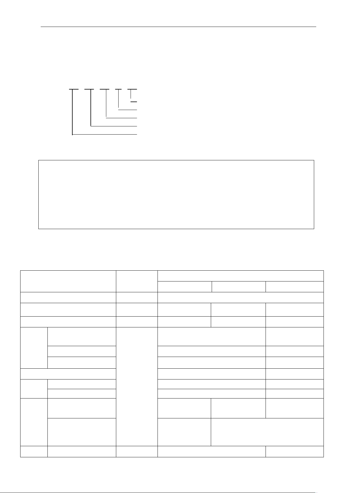
Technical specifications
TE254
TE304
TE354
380 (lower end face
of front axle shaft
8 Technical specifica tio ns
8.1product model
Tractor products LOVOL TE series have the meaning as follows:
TE □□□ ○ ○
identify mark ,expressed in the capital latin le tters
function code,mode of agriculture common uses if no expression; “t” means the mode of transp ort
type code,0 means rear wheel drive-four wheel, 4mean four wheel drive;4 mean four wheel drives
power code,expressed in the integer resulted from the nominal engine power value [unit : kw(kilowatt)] x 1.36.
Series code
The Contrast Power V alues As Follows:
Contrast Power Values T o The Product Type:
The Rated Power Of The Wheel Tractors TE254: 18.8kw (Kilowatt) (25PS)
The Rated Power Of The Wheel Tractors TE304: 22.1kw((Kilowatt) ([30 PS)
The Rated Power Of The Wheel Tractors TE354 : 23.5kw((Kilowatt) ([[32 PS)
Product Implementing Standard: Q/0704LWZ 001-2015 Wheeled T ractors
8.2 TE Pr oduct Technical Specifications
Table 8-1 Two-wheel driven tractor technical specification of LOVOL-TE series
Items Unit
Type
Standard Traction Force
Max Power Of Power Output Shaft
Length(from counterweight
Overall
Dimensio
n
to suspension)
Width
Height(to safety frame/cab)
LOVOL Europard
—— 4×4 Wheel-Type
kN
kW
6.3 7.2 8.5
16.0 18.8 21.9
3453 3500
1475 1515
2495/2335 2675/2400
Wheel
Track
Ground
Clearanc
e
Min
Wheel Track
Front Wheel
Rear Wheel
Min. Ground Clearance
(Mm)
Agriculture Clearance
Single Side Brake
mm
m
270
(
Oil drain plug of
front axle
housing)
82
1639 1796
1244 1243
960~1460 1240~1440
)
290(Oil drain plug of
front axle
400 (lower face of rear axle housing)
)
Oil drain plug of
310(
front axle
3.2±0.3 3.3±0.3
)
Page 88
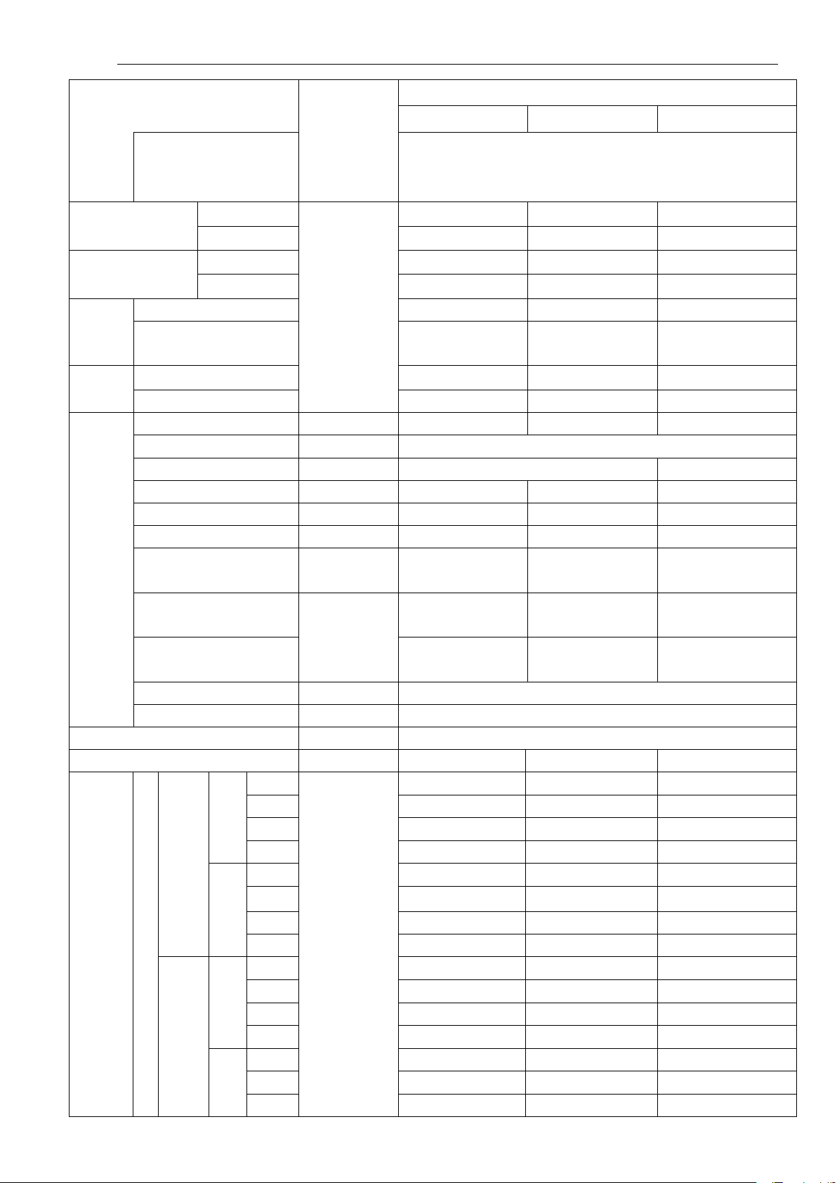
Technical specifications
——
KM385
KM390
4L22TA
——
—— 3 4
1650±100
1700±100
1650±100
Fuel consumption at rated
Oil consumption at rated
——
8+8
——
9.5-24
9.5-24/11.2-24
11.2-24/12.4-24
1 1.72
1.62/1.71
1.78/1.91
4
5.63
5.30/5.57
5.83/6.25
1
7.97
7.50/7.89
8.25/8.85
2
2.42
2.28/2.40
2.51/2.69
Steering
Cycle
Radius
Structural Quality
Structural Quality
Mass
Distributi
on Ratio
Counterw
eight
Engine
No Used Single Side Br ake
Front Wheel
Rear Wheel
Front Counterweight
Front Counterweight
Model
Type
Number of cylinders
Bore× stroke
Rated power
Rated rpm
Max. torque /speed
Items Unit
Without the cab
With the cab
Without the cab
With the cab
kg
mm 85×90 90×100 85×95
kW 18. 8 22.1 25.7
r/min 2350 2300/2400 2350
N·m/(r/min)
LOVOL Europard
TE254 TE304 TE354
3.5±0.3
1225 1435 1535
1375 1585 1685
1400 1600 1700
1550 1750 1850
630 700 740
770 900 960
80 80 80
124 124 124
Vertical, water cooled, four stroke diesel engine
83~100,
110~125,
124~132,
operation conditions
operation conditions
Way of lubrication
Way of starting
Gears
Rear Wheel Drive Specification
Forwa
S
rd
h
Gear
ut
tl
e
g
e
ar
Backw
s
ard
Gear
Lo
w
Hig
Lo
w
Hig
≤248 ≤245 ≤248
(g/kW h)
≤2.04 ≤1.47 ≤2.04
——
——
By pressure
Electrical Strating
2 2.60 2.45/2.57 2.69/2.89
3 4.08 3.84/4.04 4.23/4.53
2 12.02 11.30/11.90 12.44/13.34
h
3 18.88 17.76/18.69 19.54/20.96
4 26.02 24.48/25.76 26.93/28.89
1 1.61 1.51/1.59 1.66/1.78
3 3.80 3.58/3.77 3.94/4.22
4 5.24 4.93/5.19 5.43/5.82
1 7.42 6.98/7.35 7.68/8.24
h
2 11.19 10.53/11.08 11.59/12.43
3 17.58 16.54/17.41 18.20/19.52
83
Page 89
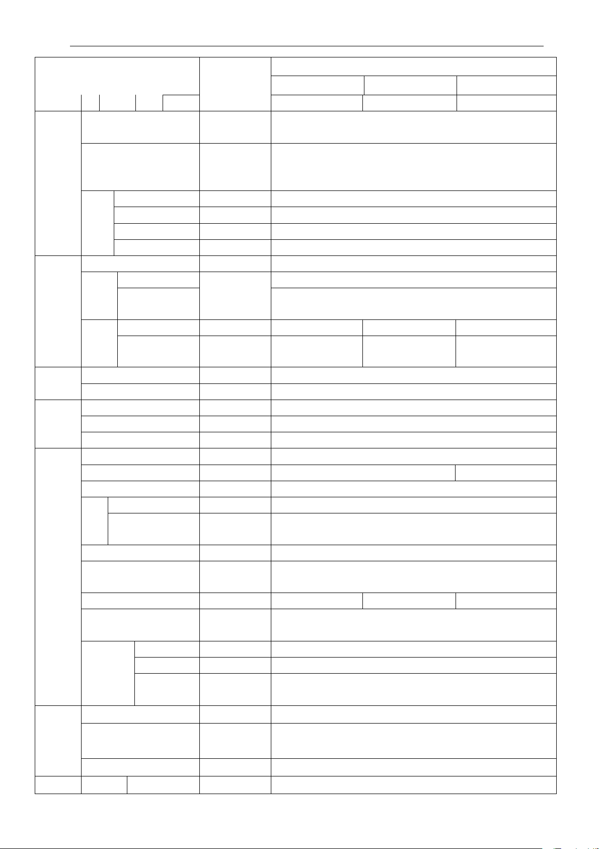
Technical specifications
Double disks, dry, disk spring pressed, constant engaged, metal and
shifting or synchronizer with shuttle gear shifting (8 forward gears and 8
——
120~150
——
——
Tilling Depth Adjustable
Items Unit
Clutch
Drive
System
Traveling
System
Steering
System
Brake
System
Work
Device
Power
Output
Shaft
Traction Traction
Gearbox
Rear
Axle
Frame
Tire
Pressu
re
Tire
Specif
ication
Way
Steering gear
Traveling Brake
Parking Bra ke
Trailer Brake Control
Hydraulic System Type
Hydraulic Pressure Oil Pump
Distributor
Oil
Tan
k
Overhang Mechanism
Way
Max Lifting Force(frame
Open Pressure Of System
Hydrauli
c Output
Form
Specification
Revolution
LOVOL Europard
TE254 TE304 TE354
4 24.24 22.80/24.00 25.09/26.91
——
ceramic friction pl ate, in-dependent dual action clutch
Mechanical transmissio n case composed of two shafts; 8 F+8R shuttle gear
——
reverse gears), sliding gear shifting;
Central Drive
Differential
Differential Lock
Rear Final Drive
Front Wheel
Rear Wheel
Front Wheel
Rear Wheel
——
——
Closed-Type,4 Bevel Plan et Gears
——
Built-In, Single Stage Straight Teeth Column Gear
——
kPa
120~150/150~180(11.2-24、12.4-24)
—— 6.0-16 6.5-16 7.5-16
—— 9.5-24 11.2-24 12.4-24
——
——
Front-wheel steering (maximum 40°, toe-in 4-10mm)
Cycloid rotary valve all hydraulic steering gear
——
——
Open-Core, Independent-Type
Bevel Gear
Dental Clutch
Half fram e
Shoe Brake
Parking Bra ke
Charging Brake
L/min 24 36
Side Valve Type
70(75、85)×105
Single-Action
Diameter× Stroke
Form
——
mm
——
Three-Points Rear Suspension,ⅠType
Position Control And Float Control
——
kN ≥5.2 ≥6.2 ≥7.2
Safety Valve
Form —— Post Built-In
Quantity —— Single-Way Hydraulic Output(Optional Two-Way Valves)
Specificatio
n
MPa
——
——
Rear positioned, non-independent-Type
Φ35,6 rectangular Tooth Clutch Spline Shaft(OptionalΦ35,8 Rectangular
17.5~18.0
M22×1.5 Or NPT1/2
——
Tooth Clutch Spline Shaft)
Form
r/min
——
540/1000(
Optional 540/760)
Rocker rod
84
Page 90
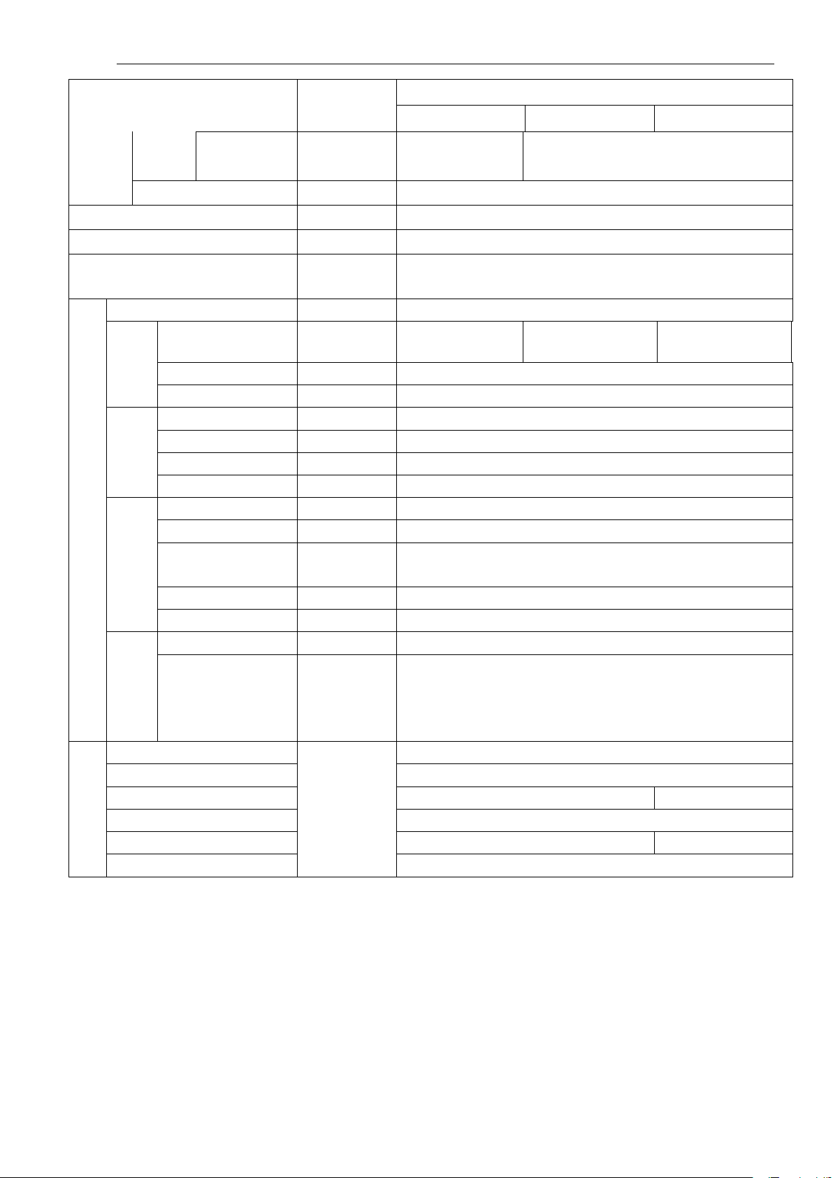
Technical specifications
0Q-12100J-1C
——
1
——
——
——
Brake Light, Left And Right Steering Lamp,
5
6
20
6
And
Pulling
Device
Elec
trica
l
Equ
ipm
ent
Instr
ume
nt
Syst
em
Perf
usio
n
Cap
abili
ty
Device
Trailer Coupling —— U-Hanger
Cab, optional
Safety Shelf
Drive Seat
Electrical System
Gener
ator
Batter
y
Light
And
Signal
Device
Monit
or And
Warni
ng
Device
Radiator
Fuel Tank
Oil Sump Of Engine
Transmission Case For Oil
Raiser For Oil
Radiator
Items Unit
Ground
mm
clearance
——
——
——
——
Model
Voltage
Power
Model
Voltage
Capability
Quantity
Headlight
Front Steering Light
Grouped Light
—— JFW15 JF11A
V 14
kW 0.35or0.5
—— 95D31
V 12
A·h 90
——
——
Rear Work Light
Trailer Socket
Instrument
Warning Device
——
——
LOVOL Europard
TE254 TE304 TE354
220~420 330~500
Closed cab (heater optional)
Two-column
Mechanical floating, PVC surface, the seat can be adjusted forward and
backward and the backrest i s adjustable
12V Negative Po le Bonding Doubl e-Wire
L375-12100-4CorL48
12V,55/60W, combined
12V,21W,2
12V, Brake Light21w,Rear Position Light5w, Steering Lamp21w, 2 for
each
12V,28W,1
7-hole Trailer Socket,1
Common combined instrument, or practical power combined instrument
Signal Light And Device:
Front /Rear Position Light, Reflector, Safety Warning Identifier
10
32
L
9.5 11
85
Page 91
Disassembly and Disposal
, never touch with skin, clothes, if so, the acid must be washed with water immediately, and seek for
medical treatment as soon as possible. Scrapped, damaged batteries is prohibited dismantling, and shall be
:
9 Disassembly and Disposal
In favor of your safety and social environment protection, the used machine shall be returned to the recycling
company with professional license for disassembly and disposal after the service life of complete machine expires.
During disassembling, the machine shall be disassembled in turn from up to down and then from exterior to
interior. When dismounting large or heavy objects, special hoister must be used. The used battery shall be returned
to the professional batte ry recycling company. Waste oil shall be collected for reasonable disposal. Do not freely
dump anywhere to pollute environment.
Warning: The battery electrolyte is corrosive and maintenance-free type, and can not be splashed into
the eyes
processed by the professional manufacturers.
Important
Do not discard the used battery acid anywhere in order to prevent environmental pollution;
The used oil is waste fuel oil. Do not discard it anywhere in order to prevent polluting environment.
We remind you that improper displacement when or after the machine is disassembled may cause injury in the
absence of special tools for disassembly or if you have no practical operational experience.
When dismounting large or heavy objects, you should use special lifting slings to ensure personal safety!
Warning:
77
Page 92

Guarantee Items
modification carried out by users or tractor application which is out of its purpose
are not included in the guarantee range provided by the manufacturer. Please
If there are faults in the machine, please inform distributors with contents as follows for guarantee: product
ine model and type, contents included in product nameplate, service time as
price and delivery date for
10 Guarantee Items
10.1 Basis for product guarantee
LOVOL series wheeled tractors are guaranteed according to the following documents and regulations.
Repair, Exchange and return Liability Provisions for Agricultural Mechanical Prod uct s SETC Quality
Product Quality Law of The People's Republic of China
Law of the PRC on the Protection of the Rights and Interests of Consumers
10.2 Conditions for guarantee nonperformance
According to relevant laws and regulations, some conditions are excluded from the range of guarantee. Refer to
vehicle document the Three Guarantees Certificate for details.
Note: Some behaviors may lead to invalidation for guarantee items. For details, please refer to Three-Guarantee
Service Certificate.
Note: Any unauthorized tractor
specified in the operation manual
pay attention to this.
Note:
1. When providing guarantee service, the user should offer his Three-Guarantee Service Certificate so that the
certificate should be kept properly;
2.
model, manufacturing no., eng
well as specific fault descriptions;
3. Repair part supply expiry date for three guarantees: it is guaranteed that repair part supply will not stop
within five years since the stop production for the product and three-guarantee parts are still in the guarantee
range. However, the delivery date for special parts should be determined after consultation within
three-guarantee period; after the expiry date for three-guarantee part supply,
supplied parts should be discussed;
4. Make sure to use special parts and oils for the product.
78
Page 93
Appendixes
Quality should be meets American Petroleum
or more, adop
35#long effective
purpose oil used for drive and hydraulic system. Executive
11 Appendixes
11.1 Oil, fuel and solution used for tractor
Table 11-1 Oil, fuel and solution used for tractor
Used parts Oil, fuel and solution
Fuel tank
Engine oil
sump
Engine
radiator
Domestic
standard
International
standard
Domestic
standard
Meet GB/T
252 light
diesel
Adopt American Society for Testing and Materials fuel D-975, with grade of 2-D
at normal temperature and with grade of 1-D at ambient temperature of below
5 ℃.
Fill fuel according to engine instruction
Over
20 ℃
~
20)℃ (-5~4)℃ (-14~-5)℃ (-29~-35)℃
(4
10# 0# -10# -20# -35#
In accordance with Society of Automotive Engineers,
International
standard
Viscosity is classified into SAE10W-40 below -5 ℃,
and SAE15W/40 over -5 ℃.
Institute API CD standard
If ambient temperature of 4℃ or more: Clean softwater
If ambient temperature of 4 ℃ or l ess: Antifreeze liquid must be used
If min. ambient temperature of -15 ℃or more, adopt -25# long effective antifreeze
(SH/T0521-1999)
If min. ambient temperature of -25 ℃
-
antifreeze(SH/T0521-1999)
If min. ambient temperature of -35 ℃or more, adopt -45# antifreeze(SH/T0521-1999)
Oil-bath type
air cleaner
Gearbox- rear
axle
Hydraulic
lifter
Front drive
axle
Brake
Oil cup
Domestic
standard
International
standard
Domestic
standard
International
standard
Domestic
standard
International
standard
Domestic
standard
International
standard
Use 10W/30 if -5℃ or less, use 15W/40 multigrade oil if -5 ℃or more.
CC or CD grade in GB 11122-2006.
In accordance with Society of Automotive Engineers,
Viscosity is classified into SAE10W-40 below -5 ℃,
and SAE15W/-40 multigrade oil over -5 ℃. Quality should b e meets Amer ican
Petroleum Institute API CD standard
N100D dual-
standard: Q/LWZ B119-2008
MF1135 from Massey Ferguson
Or M2C 86A from Ford
Or HY-GARD
TM
or J20A、J20B、J20C from John Deer
Drive hydraulic brake three-purose oil or SAE10W-40 oil
SAE10W-40 oil
General-purpose lithium base grease, subject to GB/T 7324;
SAE general purpose grease is added with 3~5% molybdenum sulfide;
Use polar region grease (MIT-G-10924C)if below -30 ℃;
Adopt National Lubrication Grea se Institute NJGI grease D-217 with 2 viscosity
grade;
79
Page 94
Appendixes
During the engine running, do not fill fuel tank. If tractor working under hot or sunlight, do not fill up fuel
the cooling water shall be clean softwater (such as rain, snow or river etc.). When using hardwater,
or jointing driven wheel hub and
199~
Bolt for coupling front outer shaft and inner
Bolts for coupling front drive wheel and
Bolts for attaching lifter housing and rear
Used parts Oil, fuel and solution
Note:
1. The dual-purpose oil for drive and hydraulic systems, diesel, diesel oil should be deposited for at least 48h to
keep its cleanness and ultimate machine performance.
2.
tank. Once the fuel is spilled, please wipe it at once.
3. Never blend the fuel of different grades and different manufactures to maintain the engine performance.
4. Choose the tractor with heater. Antifreeze must be used for winter to avoid freezing the heater.
Note:
1. During running of the engine, do not fill fuel tank, in order to avoid degerous accident;
2. If tractor is working under hot or sunlight, do not fill up fuel tank, or the fuel will be overflowed due to
expansion, once it is the case, please wipe it off at once.
Important:
such as that from wells, springs etc.), fill water tan k after it is boil ing and p recipitatin g, in order to avoid damage
to water tank.
11.2 Main bolt/ nut tightening torque table
T able 11- 2 Main bolt/ nut tightening torque table
Name and Assembly Parts Thread
Bolts, nuts for connecting engine and clutch
housing
Bolts for coupling clutch housing and the
rear axle box
Bolts for holding bearings of shaft I, shaft II
Bolt for connecting drive shaft shell and rear
axle housing
Bolts f
spoke plate
Locknut of front tie rod
shaft fittings
front wheel hub and spoke plate
specification
Grade Tightening torque N·m
M10 10.9
M12 10.9
52~90
105~156
M10 8.8 37~75
M12×1.5 10.9
M16×1.5 10.9
M16X1.5 8.8
M14 8.8
M14×1.5 10.9
106~158
240~335
270
122~185
178~235
Bolts for connecting front axle and bracket
Bolts for attaching bracket and engine
Bolts for attaching bracket and engine
axle housing
Coupling olt of limit rod bracket
M16 8.8
M12 8.8 73~110
M14X1.5 8.8 146~205
M10 10.9
M16 10.9 200~310
182~245
80
52~90
Page 95
Appendixes
use torque wrench to tighten the main bolts and nuts to avoid possible performance decreasing
Bearing NA4906
Warning:
and personal hazard etc caused by failures to meet tightening torque requirements.
11.3 Tractor roller bearing
T able 11-3 Tractor roller bearing schedule
Item
No.
1
2
3
4
5
6
7
8
9
10
Code Bearing Name and Specification Installatin position Quantity
TE250.212-04 Release Bearing 996708K Clutch Release Bearing
GB/T276 Deep groove ball bearings 6306 Main transmission assembly
GB/T276 Deep groove ball bearings 6307N Main transmission assembly
GB/T276 Deep groove ball bearings 6307N Main transmission assembly
GB/T309 Needle roller 2.5X19.8-G3X-6X-9 Main transmission assembly 28
Auxiliary transmission
GB/T309 Needle roller 2.5X19.8-G3X-6X-9
assembly
GB/T297 Bearing 32207 Rear central drive assembly
GB/T297 Bearing 31307 Rear central drive assembly
GB/T297
Tapered roller bearing 32011
GB/T276 ball bearing 6307
Differential assembly
Short axle shaft assembly 1
1
2
1
1
66
1
1
2
11
12
13
14
15
16
17
18
19
20
21
22
GB/T297 Bearing 32014
Final drive 2
GB/T297 Bearing 30211 Final drive
GB/T276 Deep groove bearing 6207 Dual-speed PTO assembly
GB/T7918 Needle roller bearing K22X30X20 Dual-speed PTO assembly
GB/T309
GB/T276
GB/T276
Tapered roller 3x23.8 Dual-speed PTO assembly
Deep groove bearing 6209
Deep groove bearing 6008
Dual-speed PTO assembly 1
Dual-speed PTO assembly
GB/T 276 Bearing 6205-Z Transfer case 1
GB/T276 Bearing 6304 Transfer case 1
GB/T276
GB/T 276
GB/T 5801
Bearing 6205
Bearing 6206
Transfer case
Transfer case 1
Transfer case 2
2
1
1
78
1
1
81
Page 96
Appendixes
operation
Item
No.
23
Code Bearing Name and Specification Installatin position Quantity
GB/T 276
Bearing 6205-Z
Transfer case
11.4 Tractor chassis seal:
T able 11-4 Tractor chassis seal schedule
Part Specification Installation position Quantity
1 GB/T3452.1
2
3
4
TL01372040028
GB/T 3452.1
GB/T 3452.1
O ring 10.6X2.65
Framed rubber oil sealing
PD35X62X12
O ring 15X2.65 Differential lock
O ring 33.5X3.55 Differential lock
Transmission case and
Transmission case and
operation
5 TS09580010009 O ring 23.6X2.9-M27X2 Dipstick of rear axle housing 1
Skeleton oil seal
6 GB/T9877.1
Axle shaft assembly 4
FB60X90X12D
1
2
2
1
7
8
9
10
GB/T3452.1 O ring 30x2.65 PTO
GB/T9877.1 oil seal B40x62x8D PTO
GB/T3452.1 O ring 80x2.65 PTO
GB/T 3452.1 O ring 15x2.65G
11 GB/T9877.1
12
13
14
GB/T3452.1 O ring 10.6X2.65G PTO operation
GB/T3452.1 O ring 45.0X3.55G Transfer case 1
TL01421010022 oil seal FB25X42X10D Transfer case 2
15 GB/T 3452.1
16 GB/T3452.1
17 GB/T 3452.1
18
19
GB/T9877.1 oil seal FB25X40X7D Drive shaft 2
GB/T 3452.1 O ring 48.7X3.55G Drive shaft 1
oil seal B50X70X8D
O ring 15.0X2.65G
O ring 46.2X3.55G
O ring 53.0X3.55G
1
1
1
Brake assembly 1
Brake assembly 2
1
Transfer case 1
Drive shaft
Drive shaft
1
1
20
GB/T 3452.1 O ring 11.2X1.80G Operation of transfer case
11.5 LOVOL series tractor matching implement
Table 11-5-1 LOVOL series tractor matching implement
82
Page 97

Appendixes
Type Tractor model
Tilling
machiner
y
Tilling
machiner
y
M254-E
Agriculture
implement
Mounted 3-
furrow plow
Mounted 2-
furrow plow
Mounted 2-
furrow plow
Agriculture
implement T y pe
1L-320
1L-325
1L-227
Rotary tilling
1GQN-125
machine
18 gap harrow 1BY-1.8
2BJ-4 (soy bean,
corn)
Main technical features:
Tilling depth(140~180)mm
Tilling depth(200~220)mm
Tilling depth(140~200)mm
Tilling depth(120~140)mm,Tilling width
1250mm
Tilling depth:(80~100)mm,Tilling width
1800mm
Sowing 4 rows, row spacing (500~700)mm
Seeding
machine
Paddy-fie
ld
operation
implemen
t
Spraying
machine
Straw
manure
M404-E
Seeder
Multi-purpose
wheat and corn
seeder
Paddy-field
puddling
machine
Suspended fight
drug machine
Field straw
chopper
2B-12/16 (wheat) Sowing 12/16 rows
2BM-2/4 (cot ton) Film mulc h sowing 2/4 rows
2BXY-12/4 Number of rows: 12 for wheat,4 for corn
1ZSN-160
Tilling depth (80~100)mm
1ZSN-180
1BSMQ-14
Tilling depth: (120~160)mm
1BSMQ-16
3W-200/6
Drug kit capacity: 200L,Spray width: 6m
Working width
4JH-1.0
1000mm,Stublle (20~80)mm
Stubble
cleaner
Stubble cleaner
Working width 1250mm, 2 ridges
1GM-2/3
tilling depth (120~150)mm
1GM-2/3 Stubble crushing blade: 400r/min
83
Page 98
Appendixes
before using the matched agricultural implement, the operator should read the “Operation and
Prior to purchase of farm machinery, refer to this schedule to select the type, model of suitable farm
soil resistance, agronomic requirements,
According to the model of tractor purchased, in combination with operating conditions (such as soil
nts, etc.), and in reference to consulting comments, the primary technical
specification for farm machinery shall be identified, to achieve a reasonable matching construction. If it is
ting efficiency of machine unit varies according to different operating conditions (such as soil
resistance, agronomic requirements, etc.). In order to ensure the best operation efficiency and performance of
speed and width in a reasonable way, which depends on
Type Tractor model
Harvestin
g
machines
Trencher
Trailer
Agriculture
implement
Agriculture
implement T y pe
Main technical features:
Soybean swather 4G-2.4 Cutting width: 2400mm
Swather 4S-170 Cutting width: 1700mm
Chain knife
trencher
(for models
YLK-20
Trenching width
: 130/160/200mm
Trench subsoiling depth: (500~1600)mm
provided with
1KS-30-25
Sulcus shape: 30*200
creeper gear)
Agriculture trailer
7CH-1.5/2
Load capacity: 1.5/2.0t
Warning:
Maintenance Manual” in detail to be familiar to structure, performance, operating method and reasonable
matching to avoid the agricultural implement and personal accidents.
Important:
1.
machinery according to the operating conditions of area (such as
etc.), more information , consult the distributor, farm machinery manufacturer;
2.
resistance, agronomic requireme
unsuitable, this can bring adverse affect on machine unit;
3. The opera
machine, the user should determine the operating
local geographical conditions.
84
Page 99

Index
12 Index
A
Safety rules and usage precautions .............................................................................................................................1
Safety warning signs ...................................................................................................................................................5
Safety Precautions ......................................................................................................................................................1
B
Guarantee Items ........................................................................................................................................................96
Conditions for guarantee nonperformance ...............................................................................................................96
C
Operation Instruction ................................................................................................................................................10
Product Identification .................................................................................................................................................9
Differential lock operation ........................................................................................................................................20
Disassembly and dispose ..........................................................................................................................................95
Basis of product warranty .........................................................................................................................................96
Product description ...................................................................................................................................................11
Product model ...........................................................................................................................................................77
Storage ......................................................................................................................................................................73
D
Chassis failure and troubleshooting ..........................................................................................................................34
Use of electrical equipment ......................................................................................................................................29
Electrical system fault and troubleshooting ..............................................................................................................41
Special maintenance for winter ................................................................................................................................49
PTO idling running-in ..............................................................................................................................................32
F
Engine start ...............................................................................................................................................................16
Start the tractor .........................................................................................................................................................18
Engine idling running-in ...........................................................................................................................................32
Engine cooling system maintenance .........................................................................................................................71
Preparations for engine start .....................................................................................................................................16
Check and change oil in the engine oil sump ...........................................................................................................67
Fan belt tension adjustment ......................................................................................................................................66
Accessories, Spare and Wearing Parts ......................................................................................................................45
Appendixes ...............................................................................................................................................................97
G
Application and maintenance of dry air filter ...........................................................................................................66
Height adjustment .....................................................................................................................................................24
124
Page 100

Index
H
Adjustment for Rear Wheel Tread ............................................................................................................................63
J
Oil filter maintenance ...............................................................................................................................................68
Technical maintenance procedures ...........................................................................................................................47
Technical Specifications ...........................................................................................................................................82
Two-wheel driven tractor technical specification of LOVOL-TE series ..................................................................82
Four-wheel driven tractor technical specification of LOVOL-TE series..................................................................86
Technical specification of TE series tractor .............................................................................................................93
Driver's seat adjustment ............................................................................................................................................23
Delivery, acception, transport, assembly and installation .........................................................................................81
Delivery and Acceptance ..........................................................................................................................................81
L
LOVOL-TE series tractor matching implement ..................................................................................................... 103
Clutch adjustment (single-acting) .............................................................................................................................51
Clutch adjustment (double-acting)............................................................................................................................52
Clutch adjustment .....................................................................................................................................................72
Tire pressure inspection ............................................................................................................................................51
Clutch failures and troubleshooting ..........................................................................................................................70
Tire removal .............................................................................................................................................................22
Tire use .....................................................................................................................................................................21
Tire use and removal and installation .......................................................................................................................21
M
Technical maintenance each shift .............................................................................................................................47
Technical maintenance after running-in ...................................................................................................................33
Preparations for running-in .......................................................................................................................................32
Technical maintenance Every 50h ............................................................................................................................47
Technical maintenance Every 200h ..........................................................................................................................47
Technical maintenance Every 400h ..........................................................................................................................48
Technical maintenance Every 800h ..........................................................................................................................48
Technical maintenance Every 1600h ........................................................................................................................49
N
Adjustment of agricultutral implement min. position ...............................................................................................64
Adjustment of agricultutral implement max. position ..............................................................................................64
P
Counterweight usage ................................................................................................................................................23
Maintenance of battery .............................................................................................................................................65
125
 Loading...