

LL
OUROEOUROE
EE
6955 VALJEAN AVE, VAN NUYS, CA 91406
LEC TRON ICSLEC TRON ICS
PH: (818)994-6498 / FAX: (818)994-6458
sales@louroe.com / www.louroe.com
INSTALLATION AND OPERATING INSTRUCTIONS
AMT-600
AUDIO LINE DRIVER
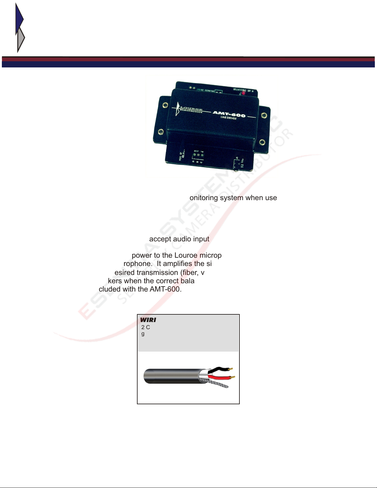
DESCRIPTION:
Model AMT-600 Line Driver is part of an audio monitoring system when used for
transmitting audio over such mediums as:
Fiber optics
Telephone wire
rf transmitters
Video Modulators that accept audio input
The AMT-600 supplies 12 Vdc power to the Louroe microphone and receives the audio
signals picked up by the microphone. It amplifies the signals to 0dB @ 600W,
balanced, for input over desired transmission (fiber, video modulators, etc). A built-in
LED illuminates and flickers when the correct balance is maintained. A power supply
(120Vac/12Vdc) is included with the AMT-600. An AMT-600 is required for each Louroe
Microphone.
WIRING REQUIREMENTS
2 Conductor shielded cable, 22
gauge with a 24 gauge drain wire
NOTE: Unshielded cable is not
satisfactory for audio systems
West Penn 452 or equivalent
PAGE 1 OF 5
amt 600(pdf) 704

INSTALLATION AND OPERATING INSTRUCTIONS
DESCRIPTION OF FUNCTIONS
[1]
[5]
FIGURE 1
[2]
[3]
AA
BB
CC
[4]
[1] - Mic Output Adjust Adjusts the level of microphone audio output. Rotate pot
clockwise to increase the level of audio output; counterclockwise
to decrease. The LED indicator lights and holds a steady low
flicker when the level of audio reaches 0dB.
[2] - Mic Input Terminal Block Connects to remote microphone. Terminal “A” supplies 12Vdc to
the microphone. Terminal “B” accepts audio from microphone.
Terminal “C” is system ground.
[3] - Power Jack Plug 12Vdc adapter (included) to power up the unit and the remote
microphone.
[4] - 0dB Indicator Indicates audio output level (0dB when illuminated and with a
steady low flicker).
[5] - Mic Output Terminal Block Connects to the audio input of the interface equipment (fiber optic
transmitter, video modulator, etc). Provides balanced 600W
audio output.
LOUROE ELECTRONICS, 6955 VALJEAN AVE., VAN NUYS, CA 91406 (818) 994-6498 FAX 994-6458
www.louroe.com / sales@louroe.com
PAGE 2 OF 5
amt 600(pdf) 704
INSTALLATION AND OPERATING INSTRUCTIONS
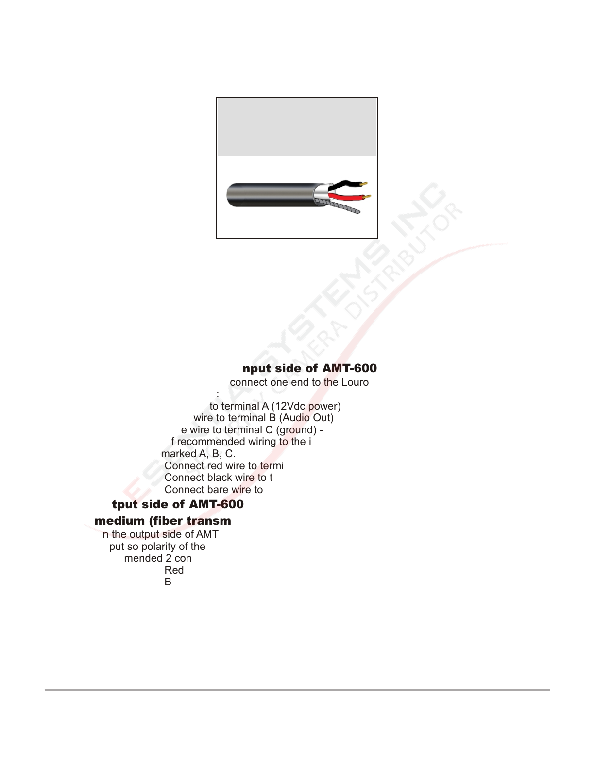
WIRING REQUIREMENTS
2 Conductor shielded cable, 22
gauge with a 24 gauge drain wire
NOTE: Unshielded cable is not
satisfactory for audio systems
West Penn 452 or equivalent
WIRING CONNECTION:
Louroe microphone to input side of AMT-600 Line Driver
Using recommended wiring, connect one end to the Louroe microphone terminal block
marked A, B, C as follows:
Red wire to terminal A (12Vdc power) +
Black wire to terminal B (Audio Out)
Bare wire to terminal C (ground) -
Run other end of recommended wiring to the input side of AMT-600 and to its terminal
block (Mic In) marked A, B, C.
Connect red wire to terminal A
Connect black wire to terminal B
Connect bare wire to terminal C
Output side of AMT-600 Line Driver to input of transmission
medium (fiber transmitter, video modulator, etc.)
On the output side of AMT-600 is a 2-pin terminal block marked Mic Out. It is a balanced
output so polarity of the 2-pin terminal block can be interchanged. Still using
recommended 2 conductor shielded cable, connect to Mic Out terminal block as follows:
Red and black wire to Mic Out terminal block (either pin)
Bare wire goes to terminal C of Mic In side of AMT-600
(see wiring connection diagram figure 2)
NOTE: For wiring connection from Output Side of AMT-600 to Audio In of transmission
medium (fiber optics, video modulator, rf transmission, etc.) Please refer to the
specific manufacturer’s installation instructions for that medium.
LOUROE ELECTRONICS, 6955 VALJEAN AVE., VAN NUYS, CA 91406 (818) 994-6498 FAX 994-6458
www.louroe.com / sales@louroe.com
PAGE 3 OF 5
amt 600(pdf) 704
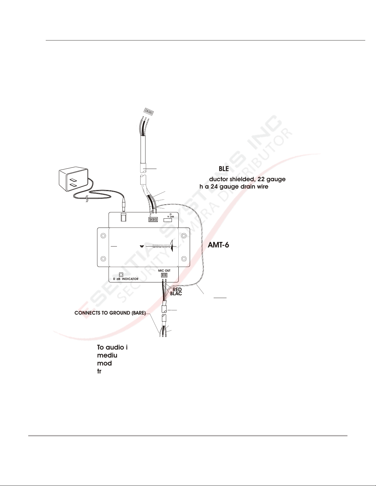
Figure 2
12 VDC
SUPPLY
INSTALLATION AND OPERATING INSTRUCTIONS
INTERCONNECTION DIAGRAM
Terminal Block of Louroe Verifact
Microphone
(Models A, B, C, D, E, K or L-DT)
IM
C
I
N
A
B
C
WEST PENN 452 CABLE
2 Conductor shielded, 22 gauge
RED
BLACK
BARE
12 Vdc
C
B
OUTPUT
A
MIC IN
with a 24 gauge drain wire
MIC ADJUST
AMT-600
AUDIO LINE DRIVER
LINE D RIVER
0 dB INDIC ATOR
CONNECTS TO GROUND (BARE)
To audio input of transmission
medium: fiber optics,
modulator, telephone wire, rf
transmitter
REFER TO THE SPECIFIC
MANUFACTURER’S INSTALLATION
INSTRUCTIONS for audio connection
MIC OUT
ELEC TRONICS
LOUROE
RED
BLACK
AMT-600 Remote Station
BARE WIRE CONNECTS TO TERMINAL C
OF INPUT SIDE OF AMT-600
AMT-600
SHIELDED AUDIO CABLE
WEST PENN 452
BLACK
RED
LOUROE ELECTRONICS, 6955 VALJEAN AVE., VAN NUYS, CA 91406 (818) 994-6498 FAX 994-6458
www.louroe.com / sales@louroe.com
PAGE 4 OF 5
amt 600(pdf) 704
INSTALLATION AND OPERATING INSTRUCTIONS
OPERATION AND TEST
After all wiring connections are complete, apply 12Vdc power to the power jack located
on the AMT-600, using the 120 Vac/12Vdc power supply (included). This will phantom
power the Louroe microphone.
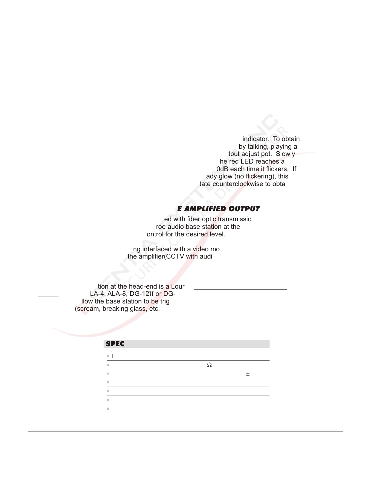
Setting the 0dB output level
Located on the output side of the AMT-600 is a red LED marked 0dB indicator. To obtain
the correct level, create some audio activity at the microphone area by talking, playing a
radio, etc. Located on the input side of the AMT-600 is a Mic Output adjust pot. Slowly
rotate clockwise to increase the level of audio output. When the red LED reaches a
steady low flicker, this indicates the audio level has reached 0dB each time it flickers. If
while rotating the pot clockwise the LED illuminates a steady glow (no flickering), this
indicates the audio level has exceeded 0dB. Slowly rotate counterclockwise to obtain the
desired level, indicated by a steady low flicker.
CHECKING THE LISTENING LEVEL AT THE AMPLIFIED OUTPUT
If the AMT-600 Line Driver is being interfaced with fiber optic transmission, rf transmitters
or telephone wire, there is usually a Louroe audio base station at the head-end for
providing audio. Adjust the volume control for the desired level.
If the AMT-600 Line Driver is being interfaced with a video modulator, check for
satisfactory audio output from the amplifier(CCTV with audio, etc.) TV set by adjusting the
volume control.
IMPORTANT NOTE
If the audio base station at the head-end is a Louroe Sound Activated Alarming Base
Station (models ALA-4, ALA-8, DG-12II or DG-25III), make sure the 0db setting at the
AMT-600 will allow the base station to be triggered if a sound exceeding the set threshold
level occurs (scream, breaking glass, etc.)
SPECIFICATIONS
Input sensitivity
Output impedance
Frequency response
Maximum output voltage
Power supply voltage
Dimensions
Weight, net
-10dB
600 balanced line
400 Hz to 10 kHz 1 dB
4 Vrms
12Vdc, 500 mA
6 1/8”L x 4 5/8”W x 1 7/8”H
6.6 oz.(0.19 Kg)
LOUROE ELECTRONICS, 6955 VALJEAN AVE., VAN NUYS, CA 91406 (818) 994-6498 FAX 994-6458
www.louroe.com / sales@louroe.com
PAGE 5 OF 5
amt 600(pdf) 704

NOTES
LOUROE ELECTRONICS, 6955 VALJEAN AVE., VAN NUYS, CA 91406 (818) 994-6498 FAX 994-6458
www.louroe.com / sales@louroe.com
amt 600(pdf) 704
IMPORTANT NOTICE
When this equipment is used as part of an
audio monitoring system, the law requires
that the public be given notice of AUDIO
MONITORING ON THE PREMISES. A
deca l notice is incl uded w ith ea ch
microphone shipped.
Federal Law References:
Federal Regulations, US Code, Title 18.
Crime and Criminal Procedure, Sec 2510.
AUDIO
MONITORING
On
These Premises
OUROE
L
LECTRONICS
E
LOUROE ELECTRONICS warrants that at the time of shipment products manufactured by LOUROE ELECTRONICS to be free of defects in material and workmanship.
Should a defect appear within one year (12 months) from date of shipment, LOUROE ELECTRONICS will, at its sole discretion, repair or replace the defective equipment.
This equipment shall not be accepted for repair or return without prior notification by LOUROE ELECTRONICS.
This warranty does not extend to any Louroe product that has been subjected to improper or incorrect installation, misuse, accident, or in violation of installation
instructions provided by LOUROE ELECTRONICS.
WARRANTY
Returned shipments to LOUROE ELECTRONICS shall be at customer’s expense. LOUROE ELECTRONICS will return the equipment prepaid via best way.
LOUROE ELECTRONICS, 6955 VALJEAN AVE., VAN NUYS, CA 91406 (818) 994-6498 FAX 994-6458
www.louroe.com / sales@louroe.com
amt 600(pdf) 704

LL
OUROEOUROE
EE
LECTR ONICSLECTR ONICS
MANUFACTURED
IN THE
LOUROE ELECTRONICS 6955 VALJEAN AVENUE, VAN NUYS, CA 91406 TEL (818) 994-6498 FAX (818) 994-6458
Website: www.louroe.com Email: sales@louroe.com
 Loading...