

Page 1

Installation and operating instructions
PROFESSIONAL GAS FULL-PLATE
COOKER
TP-94G TP2-98G TP4-912G TPF2-98G TPF2-98GE TPF4-912GV
TPF4-912GEV TPF4-912G TPF4-912GE TPT-94G TP2T-98G TP4T-912G
TPFV2-98GE TPFV4-912GEV
Model LIBR.ISTR.TP 90G MOD.40
Code 563009102
Review 1
Edition date 21/11/2018
Language English
LOTUS S.p.A.
Via Calmaor, 46
31020 San Vendemiano
+39 0438 778020
+39 0438 778277
Instructions in original language
Page 2

Contents
Contents
1 INTRODUCTION......................................................................................................................... 3
1.1 Installation drawing...................................................................................................................... 3
1.2 Components................................................................................................................................. 4
1.3 Example installation of the appliance........................................................................................... 12
2 GENERAL INFORMATION......................................................................................................... 13
2.1 Declaration of compliance............................................................................................................ 13
2.2 User information, RAEE Directive on waste electrical and electronic equipment ........................ 14
2.3 Technical data table..................................................................................................................... 14
3 INSTALLATION........................................................................................................................... 17
3.1 Delivery checks ............................................................................................................................ 17
3.2 Removing the packaging ............................................................................................................. 17
3.3 Mechanical installation ................................................................................................................. 17
3.4 Electrical/gas connections ........................................................................................................... 17
4 BURNERS TECHNICAL DATA TABLE (ITGB).......................................................................... 22
4.1 Burners technical data table ........................................................................................................ 22
5 INSTRUCTIONS FOR USE......................................................................................................... 23
5.1 General information ..................................................................................................................... 23
5.2 Lighting and adjusting the open rings.......................................................................................... 23
5.3 Starting the main burner and adjusting the temperature.............................................................. 23
5.4 Switching the main burner off ...................................................................................................... 24
5.5 Turning the appliance off.............................................................................................................. 24
5.6 Lighting and regulating gas oven burner...................................................................................... 24
5.7 Turning on and adjusting the static oven ..................................................................................... 24
5.8 Turning on and adjusting the fan oven......................................................................................... 25
5.9 Cooking table for the fan oven ..................................................................................................... 26
6 MAINTENANCE.......................................................................................................................... 28
6.1 Routine......................................................................................................................................... 28
6.2 Changing the open ring nozzles (fig. C)....................................................................................... 28
6.3 Substituting the nozzle in the pilot burner (fig. D)........................................................................ 28
6.4 Substituting the nozzle in the oven burner ................................................................................... 29
6.5 Minimum setting ........................................................................................................................... 29
6.6 Spare parts .................................................................................................................................. 29
7 CLEANING.................................................................................................................................. 30
7.1 Routine cleaning.......................................................................................................................... 30
Instructions in original language
2
Page 3
INTRODUCTION
1 INTRODUCTION
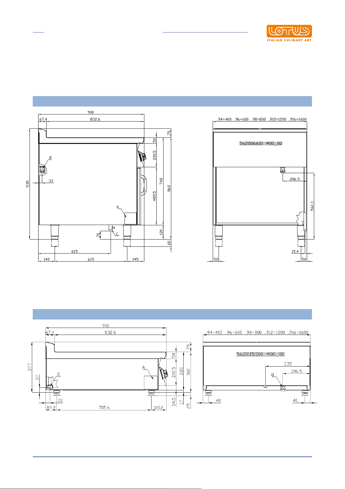
1.1 Installation drawing
FIG. 1 TP…-9G..
A Data Plate
B Electrical connection
C Gas connection
A Data Plate
C Gas connection
FIG. 2 TP...T
Instructions in original language
3
Page 4
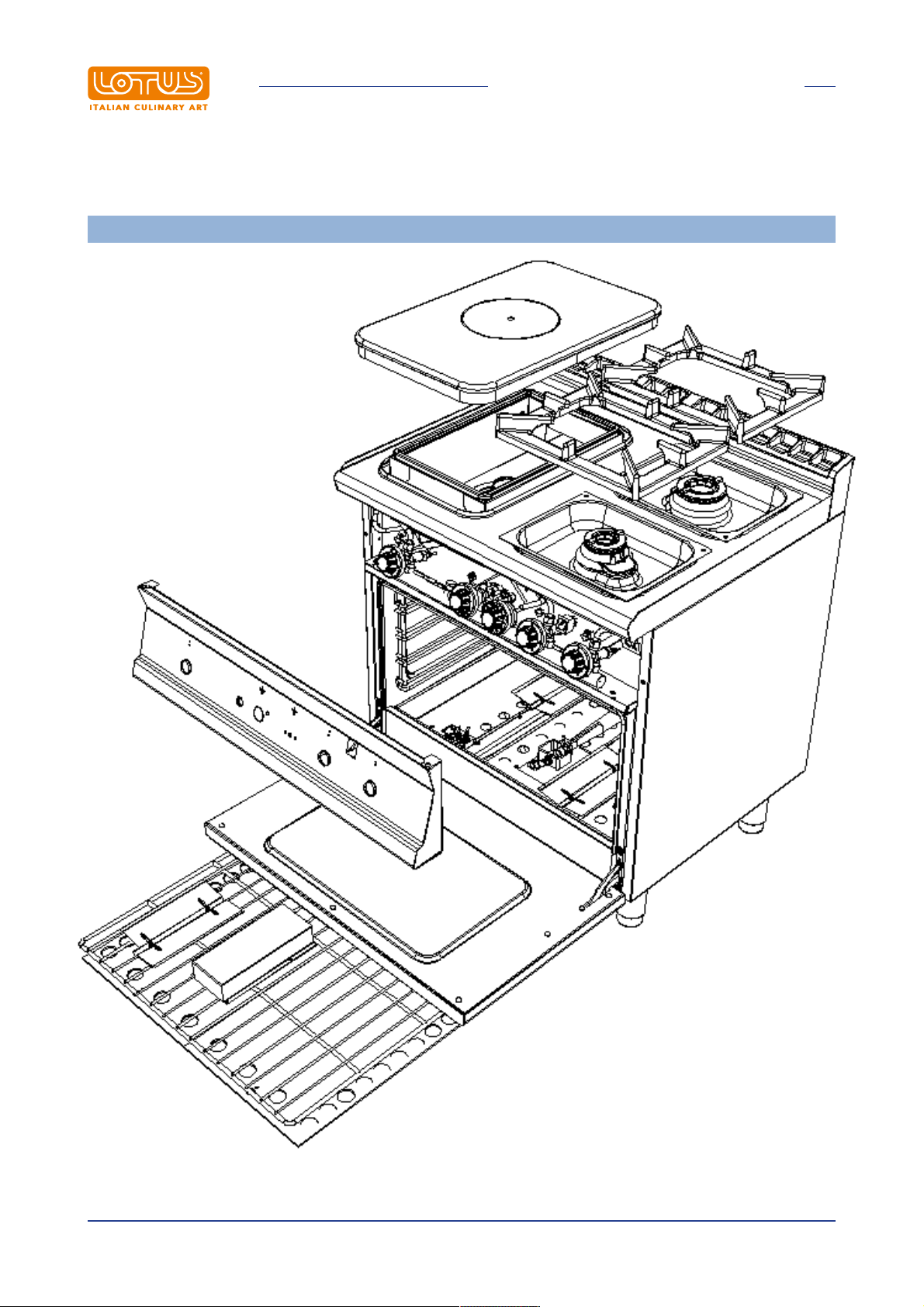
1.2 Components
INTRODUCTION
FIG. H
Instructions in original language
4
Page 5
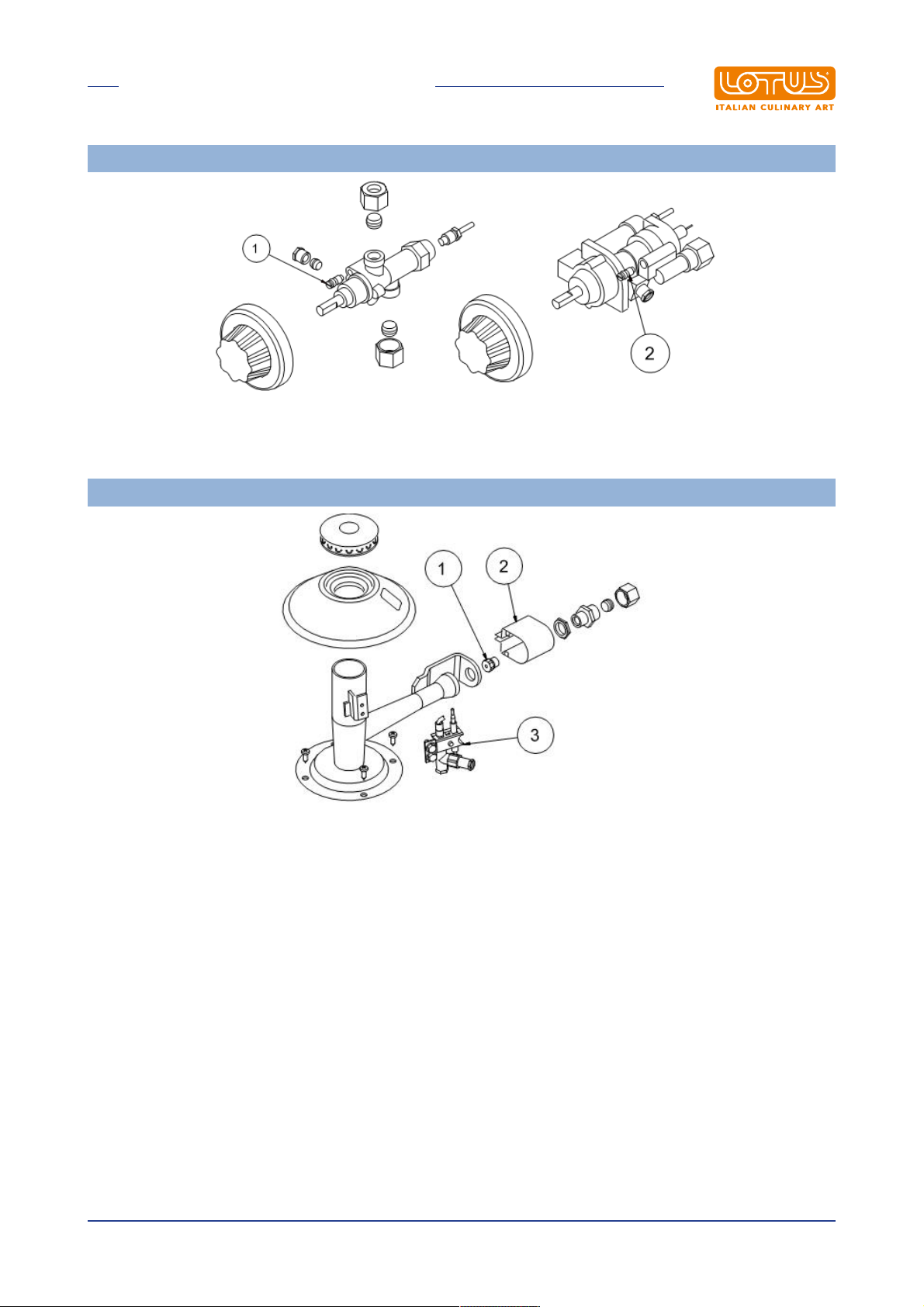
1 Flame open by-pass
2 Oven by-pass
INTRODUCTION
FIG. B
FIG.C (FLAMES)
1 Flame injector
2 Air adjustment
3 Pilot
Instructions in original language
5
Page 6
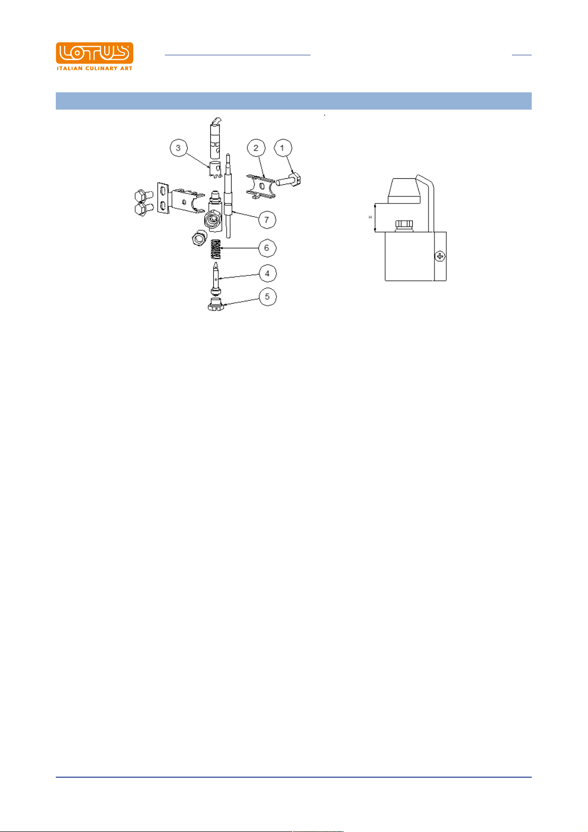
1 Pilot bracket screw
2 Pilot bracket
3 Pilot air bushing
4 Pilot injector
5 Injector screw
6 Spring
7 Extends drainage
INTRODUCTION
FIG. D (Fire pilot)
Instructions in original language
6
Page 7
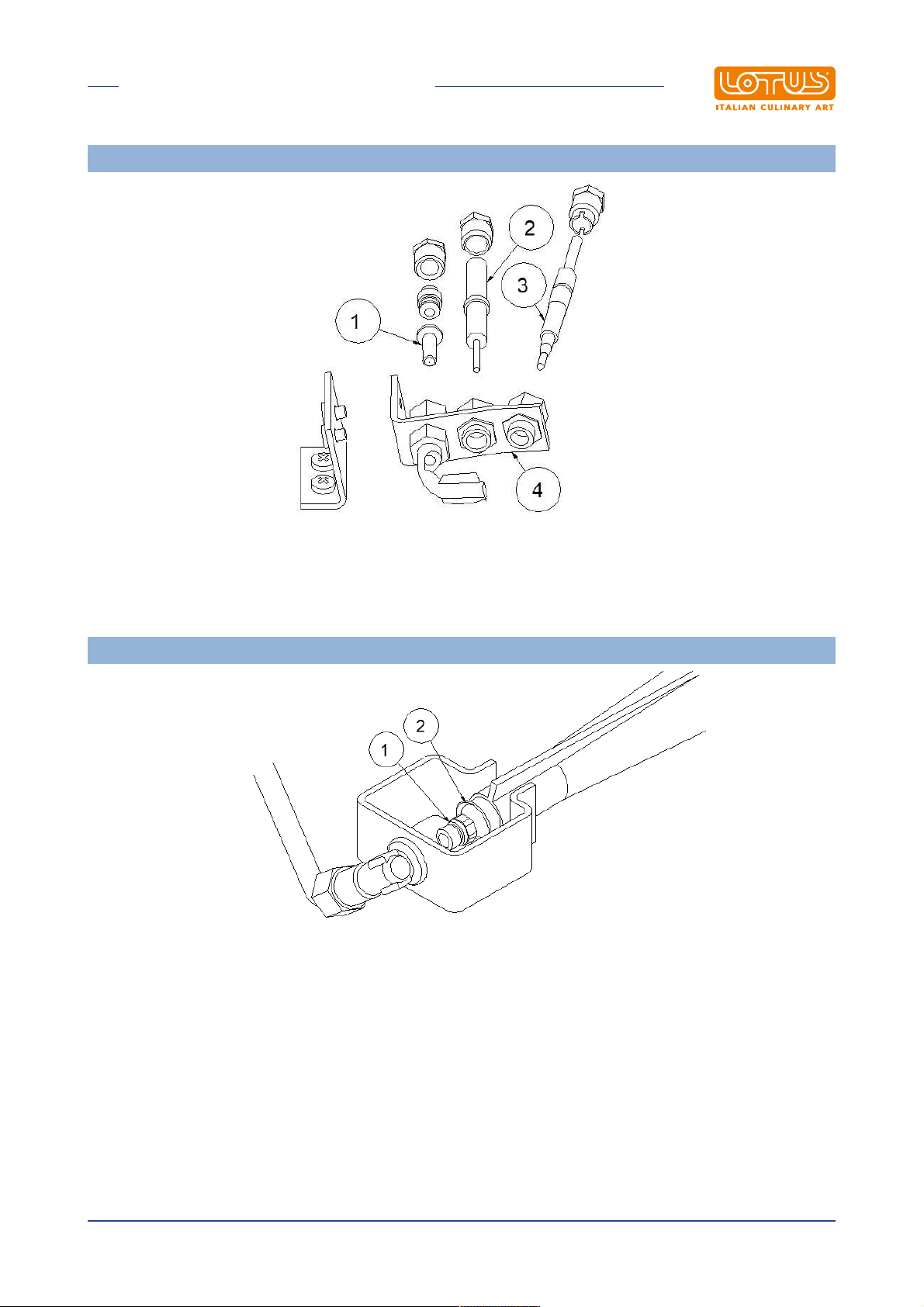
1 Pilot light nozzle
2 Ignition spark plug
3 Extends drainage
4 Pilot bracket
INTRODUCTION
FIG. F (Oven pilot)
FIG. E
1 Oven injector
2 Oven air regulation
Instructions in original language
7
Page 8
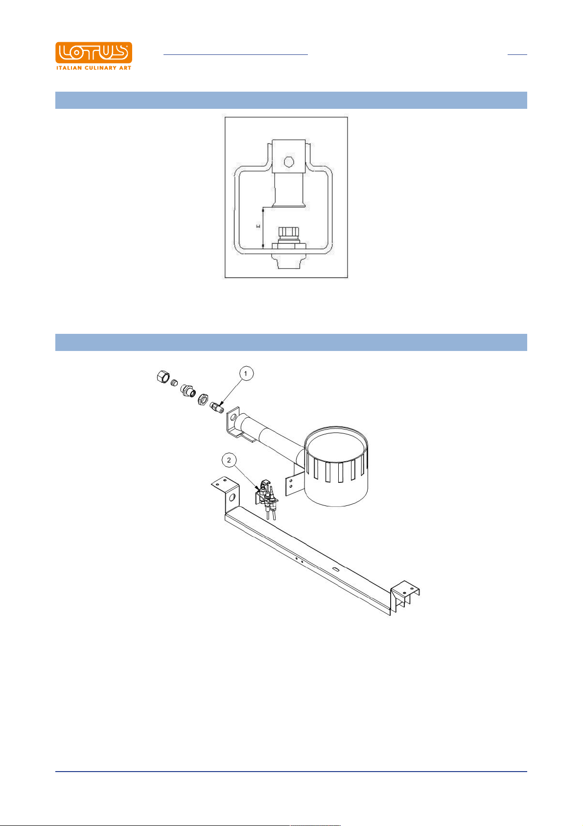
Burner air adjustment
INTRODUCTION
FIG. G
FIG. I
1 Injector
2 Pilot
Instructions in original language
8
Page 9
INTRODUCTION
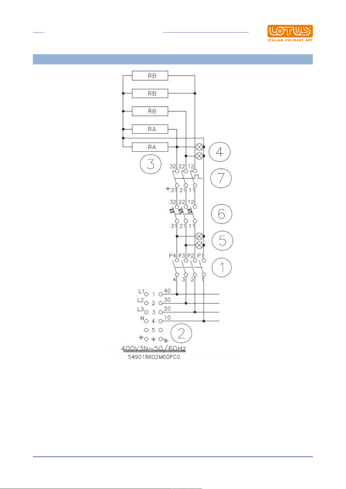
WIRING DIAGRAM OVEN GN 2/1 (H)
1 Switch
2 Power supply terminal board
3 Heating element
4 White indicator light
5 Green indicator light
6 Thermostat
7 Safety thermostat
Instructions in original language
9
Page 10
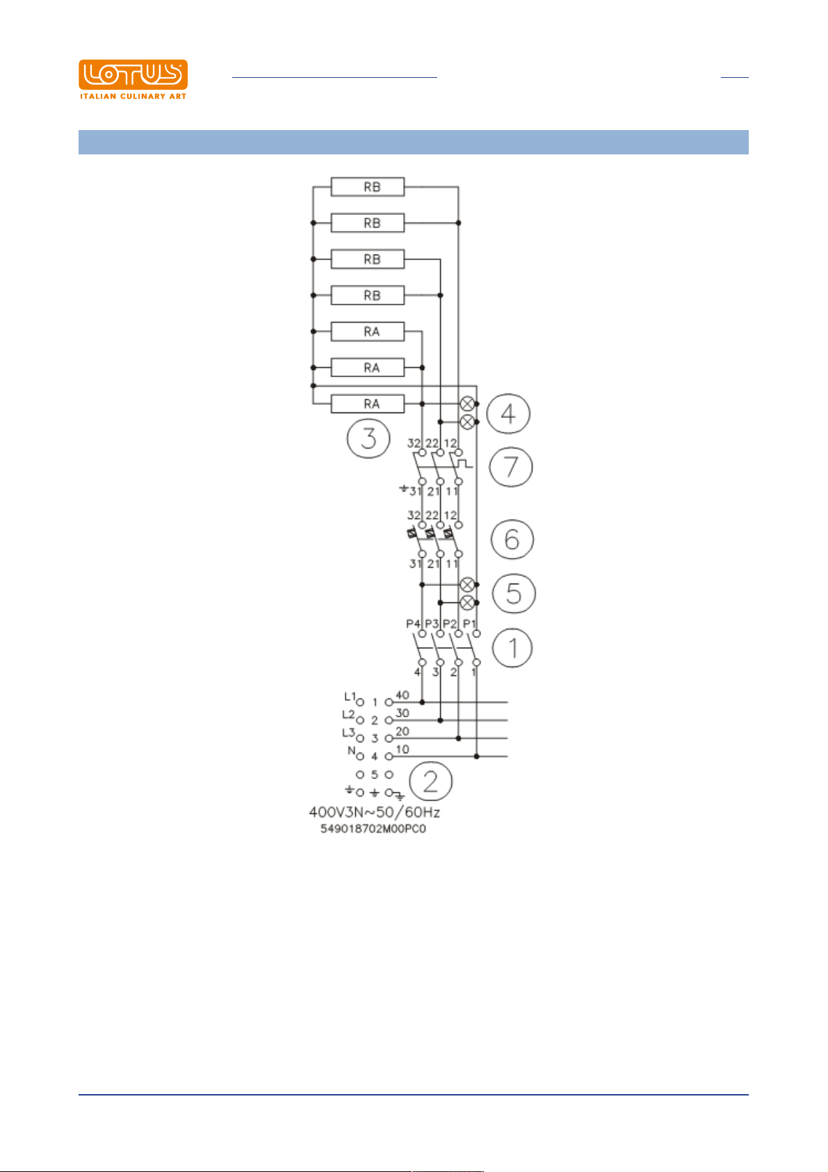
WIRING DIAGRAM OVEN GN 3/1 (I)
INTRODUCTION
1 Switch
2 Power supply terminal board
3 Heating element
4 White indicator light
5 Green indicator light
6 Thermostat
7 Safety thermostat
Instructions in original language
10
Page 11
INTRODUCTION
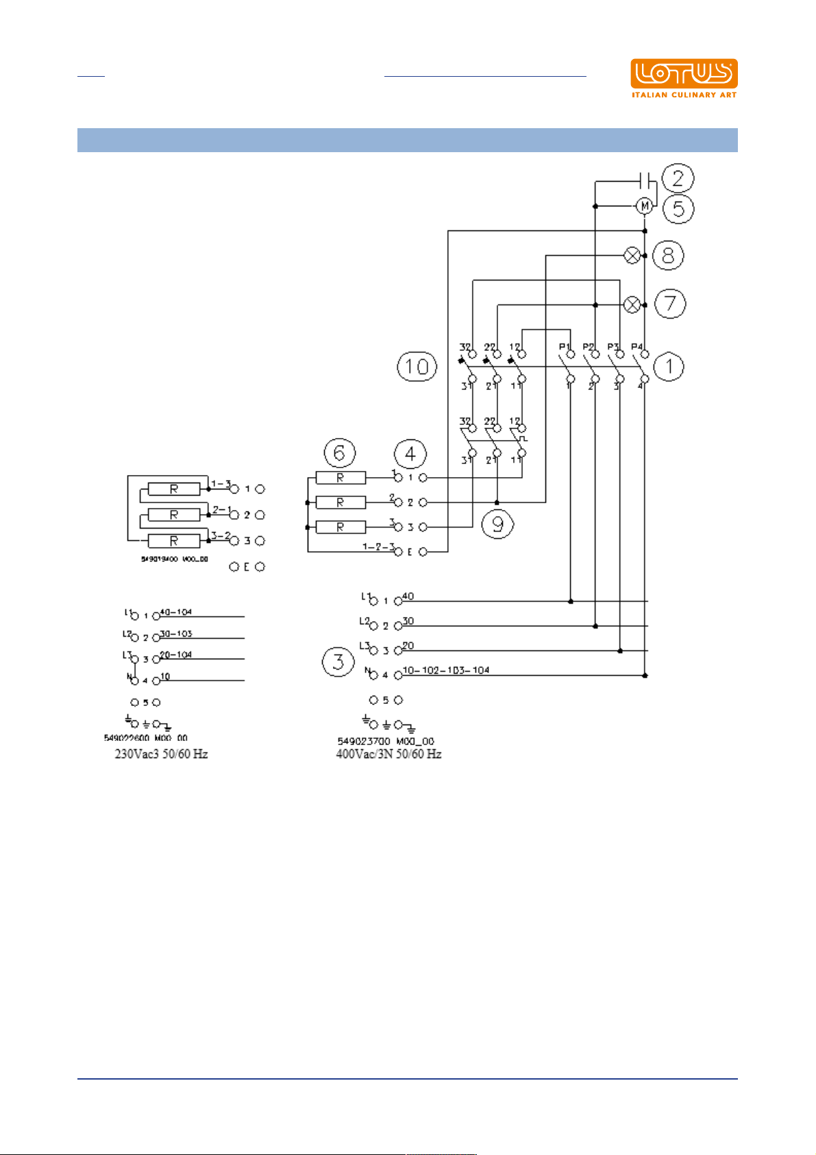
VENTILATED ELECTRICAL OVEN
1 Switch
2 Condenser
3 Power supply terminal board
4 Switching terminal board
5 Motor
6 Heating element
7 White indicator light
8 Green indicator light
9 Safety thermostat
10 Thermostat
Instructions in original language
11
Page 12
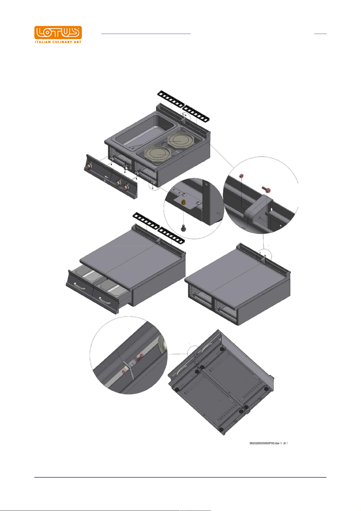
1.3 Example installation of the appliance
INTRODUCTION
Instructions in original language
12
Page 13

GENERAL INFORMATION
2 GENERAL INFORMATION
2.1 Declaration of compliance
The manufacturer declares that the appliances comply with the requirements of the regulation GAR
2016/426 for the gas part and directive 2014/30/EU,2014/35/EU for the electrical part. Installation must be
performed in compliance with current regulations, especially with regard to ventilation of the premises and
the exhaust gas evacuation system.
· Read the warnings in this manual carefully. They provide important information about safe installation,
use and maintenance.
· The instruction manual must be kept for the entire duration of the equipment and made available to users
for every possible consultation. The manual should be consulted for any information concerning
installation, use and maintenance of the appliance.
· After removing the packaging, check the integrity of the equipment.
· All packaging materials (plastic bags, polystyrene, staples, etc.) must be disposed of in compliance with
current regulations.
· Before connecting the appliance, make sure that the information on the data plate matches the electricity
and gas mains where the appliance is installed. The manufacturer accepts no liability if the
equipment is not connected in accordance with current regulations.
· Always keep all parts of the equipment clean to avoid the risk of oxidation/rust and/or aggression by
chemical agents.
· The equipment must only be used by personnel trained for the purpose.
· The installation must be implemented by professionally qualified personnel in accordance with
the manufacturer's instructions and current reference standards.
· The electrical safety of this equipment is only ensured when it is correctly connected to an effective
ground/earth system as required by current electrical safety standards. The manufacturer cannot be held
liable for any damage caused if the system is not connected to ground/earth.
· Before carrying out any cleaning or maintenance tasks on the equipment, unplug it from the electricity
mains. In the event of faults or malfunctions, always deactivate the appliance.
· Repair work of any kind must only be performed by qualified personnel.
· This appliance must only be used for its expressly intended purpose for cooking or heating food. Any
other use is considered improper.
· The appliance is intended for professional use and must be used by trained personnel.
· The installation and possible transformation to another power supply voltage (if envisaged), or
transformation for operation with another type of gas, must be implemented exclusively by qualified and
authorised professional personnel.
· Before using the appliance, carefully clean all surfaces intended to come into contact with food.
· The manufacturer declines any and all liability for any direct or indirect damage resulting from improper
use of the equipment. The manufacturer declines any and all liability for damage caused by incorrect
installation, tampering, poor maintenance and unskilled use. Moreover, the manufacturer declines any
liability for possible inaccuracies that may be contained in this booklet attributable to errors in
transcription or printing and equally reserves the right to make any changes to the product it deems
useful and/or necessary without compromising its essential characteristics.
· The manufacturer cannot be held liable for any damage caused by failure to comply with these
basic standards and all other use and maintenance standards contained in this booklet.
Instructions in original language
13
Page 14
GENERAL INFORMATION
2.2 User information, RAEE Directive on waste electrical and
electronic equipment
With regard to the regulatory framework of reference of the European Community, we remind the user of the
following:
· Used AAE (Electrical and Electronic Equipment) products must be collected separately
· The user can carry out this collection in the RAEE collection systems and return the equipment to the
distributor when purchasing a new one
· Plus being RoHS compatible, (in accordance with Directive 2011/65/EU on the restriction of the use of
certain hazardous substances in electrical and electronic equipment) the potential effects on the
environment and human health may be due to the misuse of the same equipment or parts of it
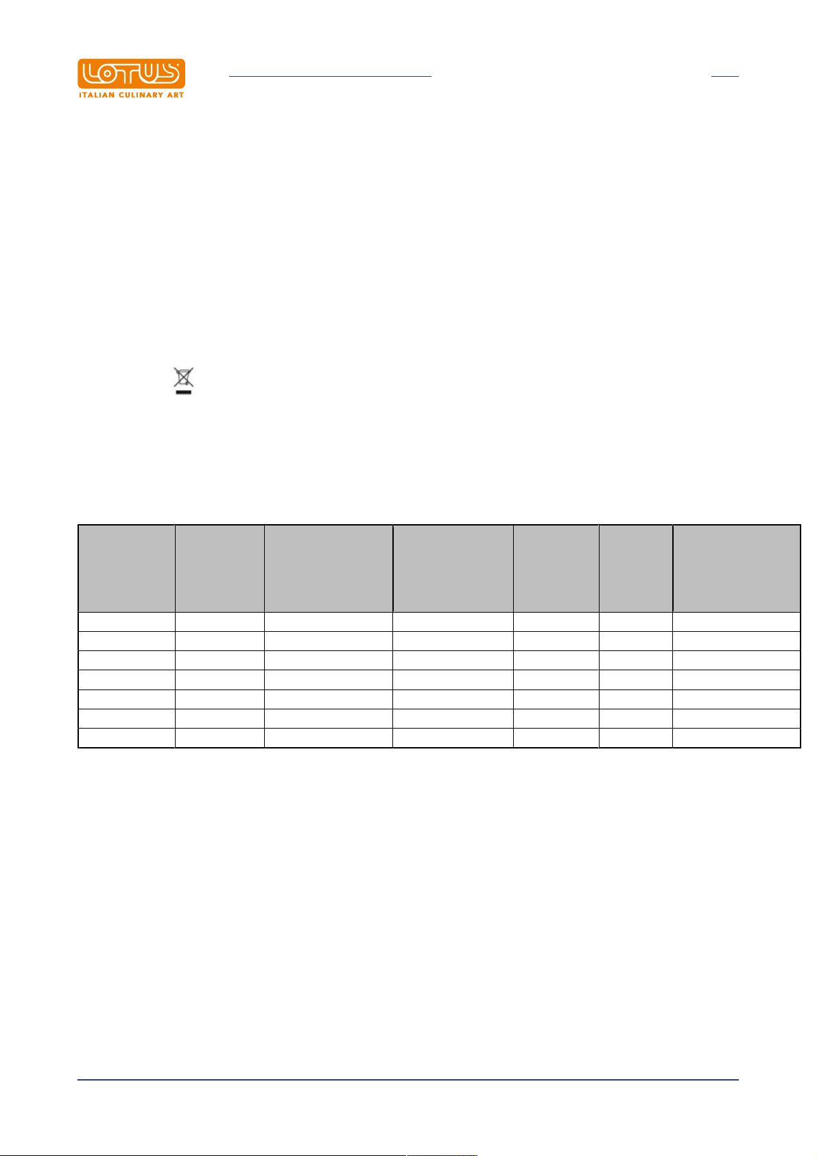
· The symbol next to the rating plate indicates the obligation of separate collection
· The penalties provided for in the event of improper disposal of RAEE (Waste Electrical and Electronic
Equipment) are those provided for by the national transpositions of European Directives 2012/19/EU
2.3 Technical data table
Electrical technical data table TPF S90GE
MAXIMUM
ELECTRICA
L
POWER
Emissivity
dB (A)
MODEL
DIMENSION
S
POWER SUPPLY
MAXIMUM
ABSORPTION (A)
(kW)
TPF2-98GE 80x90x90h 400V~3N 50/60 Hz 10,9 6,7 / 5 x 1,5 mm²
TPF4-912GEV 120x90x90h 400V~3N 50/60 Hz 10,9 6,7 / 5 x 1,5 mm²
TPF4-912GE 120x90x90h 400V~3N 50/60 Hz 14,8 9,2 / 5 x 1,5 mm²
TPFV2-98GE 80x90x29h 400V~3N 50/60 Hz 8,06 5,32 <70 5 x 1,5 mm²
TPFV2-98GE 80x90x29h 230V~3 50/60 Hz 13,35 5,32 <70 4 x 1,5 mm²
TPFV4-912GEV 120x90x90h 400V~3N 50/60 Hz 8,06 5,32 <70 5 x 1,5 mm²
TPFV4-912GEV 120x90x90h 230V~3 50/60 Hz 13,35 5,32 <70 4 x 1,5 mm²
POWER SUPPLY
CABLE
silicon type
Instructions in original language
14
Page 15
GENERAL INFORMATION
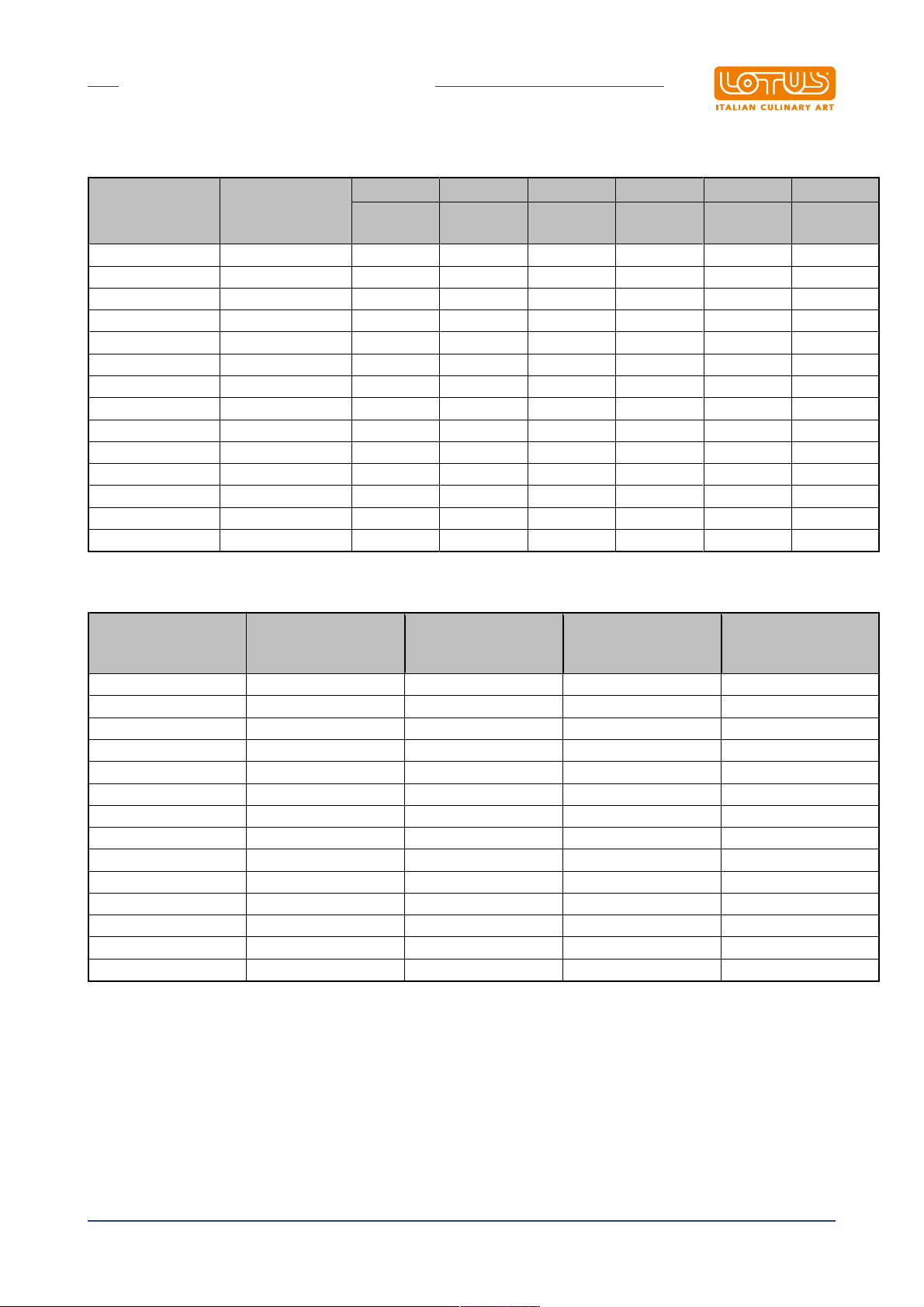
Technical data table 1
BURNER BURNER BURNER BURNER BURNER BURNER
MODEL DIMENSIONS
TPF2-98G 80x90x90h 1 1 1 / 1 /
TP-94G 40x90x90h 1 / / / / /
TP2-98G 80x90x90h 1 1 1 / / /
TP4-912G 120x90x90h 1 1 2 1 / /
TPF2-98GE 80x90x90h 1 1 1 / / /
TPFV2-98GE 80x90x90h 1 1 1 / / /
TPF4-912GV 120x90x90h 1 1 2 1 1 /
TPF4-912GEV 120x90x90h 1 1 2 1 / /
TPF4-912G 120x90x90h 1 1 2 1 / 1
TPF4-912GE 120x90x90h 1 1 2 1 / /
TPFV4-912GEV 120x90x90h 1 1 2 1 / /
TPT-94G 40x90x29h 1 / / / / /
TP2T-98G 80x90x29h 1 1 1 / / /
TP4T-912G 120x90x29h 1 1 2 1 / /
TP
7 kW
FLAMES
10 kW
FLAMES
7 kW
FLAMES
4 kW
OVEN
8,5 kW
OVEN
13 kW
Technical data table 2
RATED
MODEL DIMENSIONS
TOTAL GAS FLOW
(kW)
TPF2-98G 80x90x90h 32,5 R 3/4GM B11
TP-94G 40x90x90h 7 R 1/2GM A
TP2-98G 80x90x90h 24 R 3/4GM A
TP4-912G 120x90x90h 35 R 3/4GM A
TPF2-98GE 80x90x90h 24 R 3/4GM A
TPFV2-98GE 80x90x90h 24 R 3/4GM A
TPF4-912GV 120x90x90h 43,5 R 3/4GM B11
TPF4-912GEV 120x90x90h 35 R 3/4GM A
TPF4-912G 120x90x90h 48 R 3/4GM B11
TPF4-912GE 120x90x90h 35 R 3/4GM A
TPFV4-912GEV 120x90x90h 35 R 3/4GM A
TPT-94G 40x90x29h 7 R 1/2GM A
TP2T-98G 80x90x29h 24 R 3/4GM A
TP4T-912G 120x90x29h 35 R 3/4GM A
GAS FITTING
ISO 7-1
FUME DISCHARGE
TYPE
Instructions in original language
15
Page 16
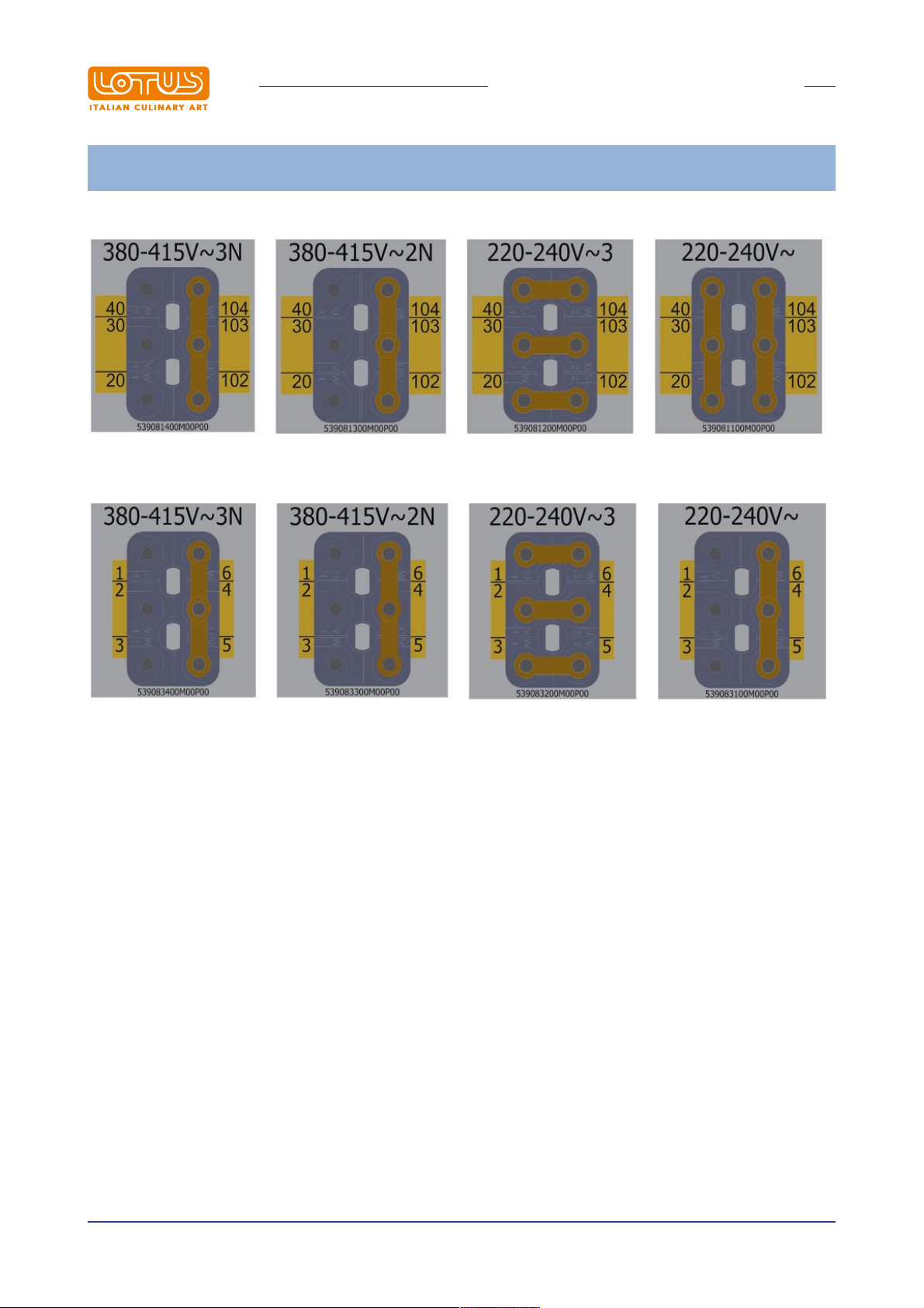
GENERAL INFORMATION
DESIGN ASSEMBLY/TRANSFORMATION ELECTRICAL LINKING TERMINAL BLOCK PERNIONS (see
technical data table)
· POWER SUPPLY CONNECTION
· HEATING ELEMENT CONNECTION
Instructions in original language
16
Page 17

INSTALLATION
3 INSTALLATION
3.1 Delivery checks
On delivery, it is important to check the following:
· External conditions of the packaging
· The general status of the equipment
· The conformity of the model with the information in the technical data plate and the instruction manual
· The conformity of the equipment and components to the order form
3.2 Removing the packaging
While removing the packaging, take care not to damage the appliance. Remove the protective film from the
stainless steel and eliminate any traces of glue. Do not smoke. Perform this operation away from sources of
heat and wear protective gloves. Do not disperse packaging material in the environment, keep it out of the
reach of children and dispose in compliance with current legislation.
3.3 Mechanical installation
Place the appliance on a flat base. Adjust and stabilise the appliance by acting on the support feet. Make
sure that the surrounding walls and/or equipment are capable of withstanding the heat emitted by this
appliance. Connect the water supply (if necessary).
Caution
Do not install the appliance near equipment/machines used in cold processes. If the appliance
has to be installed close to cold process equipment, it is advisable to install non-combustible
thermal insulating material and/or neutral elements between them.
3.4 Electrical/gas connections
Before being offered for sale on the market, the appliance was subjected to gas and electrical testing (as
required). The appliance is supplied without a power cable. The installation technician must connect the
equipment in compliance with current safety regulations on the basis of the power of the appliance.
Note
The ID plate is located in the compartment inside the door for appliances with compartments, or on
the left side for appliances with an oven or a top. A second plate with the model and serial number is
located inside the dashboard and a third is included with the certificate of conformity. The serial
number can also be tracked from the sales document (after 2008). The plate has all the data needed
for correct electrical installation. The installation and possible conversion to another power supply
voltage (if envisaged) must be implemented exclusively by professionally qualified and authorized
personnel. Before using the appliance, carefully clean all surfaces intended to come into contact with
food.
Instructions in original language
17
Page 18
INSTALLATION
Warning
Installation operations, any conversion to other types of gas and start-up must only be
performed by qualified personnel, in accordance with current regulations.
Gas systems, electrical connections and premises where the appliances are installed must comply with
current regulations in the country of installation; in particular, the appliance must be installed in a room with
good ventilation, if possible under a suction hood to ensure complete evacuation of the exhaust gases
formed during combustion. The air required for combustion is 2 m3/h per kW of installed power. The
appliance can be installed alone or in series with other appliances in our production range. A minimum
distance of 10 cm between appliances must be respected to prevent contact with any walls made of
flammable material; furthermore, appropriate measures should also be adopted to ensure the thermal
insulation of flammable parts, such as the installation of heat shields; take special care to ensure that
appliances are installed in an appropriate and safe manner. The support feet can be adjustable in height and
any unevenness can therefore be eliminated.
ELECTRICAL CONNECTION
Caution
In accordance with international provisions, when connecting the appliance an automatic
device must be installed up-line of it so that the device can be fully disconnected from the
mains; this device must have a contact aperture of at least 3 mm.
The connection terminal is located behind the rear wall. Proceed as follows to install the power supply cable:
· Remove the rear panel.
· Pass the new connection cable through the cable gland, connect the leads to the corresponding terminal
on the terminal block and fasten them securely.
· Lock the cable with the cable gland and refit the panel. The earth/ground lead must be longer than the
others so that if the cable gland breaks it is disconnected after the power cables.
Note
Make sure that the mains voltage complies with the data on the appliance's ID plate and that there is
good conductivity to earth/ground. Pay attention when inserting leads to ensure they do not obstruct
the normal course of work and routine appliance cleaning operations. Also make sure that the power
cable is never pulled taut and is not placed in contact with sources of heat.
Note
The connection cable must have the following characteristics: it must be silicone type (to
withstand temperatures of 180 °C), and must have an appropriate cross-section for the power
of the appliance (see technical data table).
EQUIPOTENTIAL
The appliance must be connected to an equipotential system. The connecting screw is located on the rear of
the appliance and is marked by the yellow symbol above it.
Warning
The manufacturer is not liable for and does not indemnify damages caused by incorrect
inadequate installations that do not comply with these instructions.
GAS CONNECTION
The gas connection (see installation drawing) must be implemented using steel or copper pipes or steel
hoses, in compliance with applicable national standards. All appliances must be equipped with a gas shut-off
Instructions in original language
18
Page 19

INSTALLATION
valve and fast-closing valve. Once installation is complete, make sure that there are no gas leaks from the
fittings; to do this, do not use a naked flame but substances that do not cause corrosion, such as solutions of
soapy water or leak detectors. All our appliances are subjected to detailed examination: the type of gas,
pressure in use and the pertinent category are indicated on the data plate (see attachment).
Note
The year of construction of the appliance is indicated under "N" on the data plate. The first 2 digits
indicate the year of construction.
· THERMAL OUTPUT CONTROL
The appliances must be checked in order to verify that their thermal output is correct:
· Thermal output is indicated on the appliance's data plate;
· Firstly, make sure that appliance is set for the type of gas used and then make sure that the indication on
the data plate matches this gas. To adapt the appliance to another type of gas, make sure that the type of
gas in question complies with the information in this instruction manual.
Warning
Pressure is measured with a pressure gauge (minimum resolution of 0.1 mbar) mounted on
the appropriate socket. Remove the M6 locking screw and insert the pressure gauge tube.
The test must be performed with all the burners on the appliance switched on and all the
appliances in the same line switched on. After taking the measurement, replace the screw,
firmly tighten and check the seal.
Liquid gas connection G30 / G31
The liquid gas connection pressure is 30 mbar for butane and 37 mbar for propane. Check the data plate,
measure the pressure and verify that the description of the nozzle installed matches the information provided
by the manufacturer.
Methane gas connection H G20
The methane gas connection pressure is 20 mbar. Check the data plate, measure the pressure and verify
that the description of the nozzle installed matches the information provided by the manufacturer.
· CHECKING THE PRIMARY AIR FOR MAIN BURNERS AND PILOT NOZZLE
For burners equipped with air adjustment, set the adjustable bushing and lock it with a screw. The "Burner
technical data" table shows approximate values for the "h" parameter (primary air). The primary air flow
volume must be adjusted to avoid a flame cut-off when the burner is cold and a flame blowback when the
burner is hot. The pilot air adjustment is set testing for the gas which the appliance will use. In the event of
conversion to other types of gas, adjust the air using the adjustment bush until the pilot flame is steady and
has an intense blue colour.
Disposition for conversion and installation for other types of gas:
Our appliances are tested and set for liquid gas or natural gas (see attached data plate). Conversion or
adaptation to another type of gas must be performed by a specialist technician. The nozzles for the various
types of gas are contained in a bag included in the supply and are marked in hundredths of mm (see
"Burners" technical data table).
· INSTRUCTIONS FOR EVACUATING EXHAUST GASES
Instructions in original language
19
Page 20
INSTALLATION
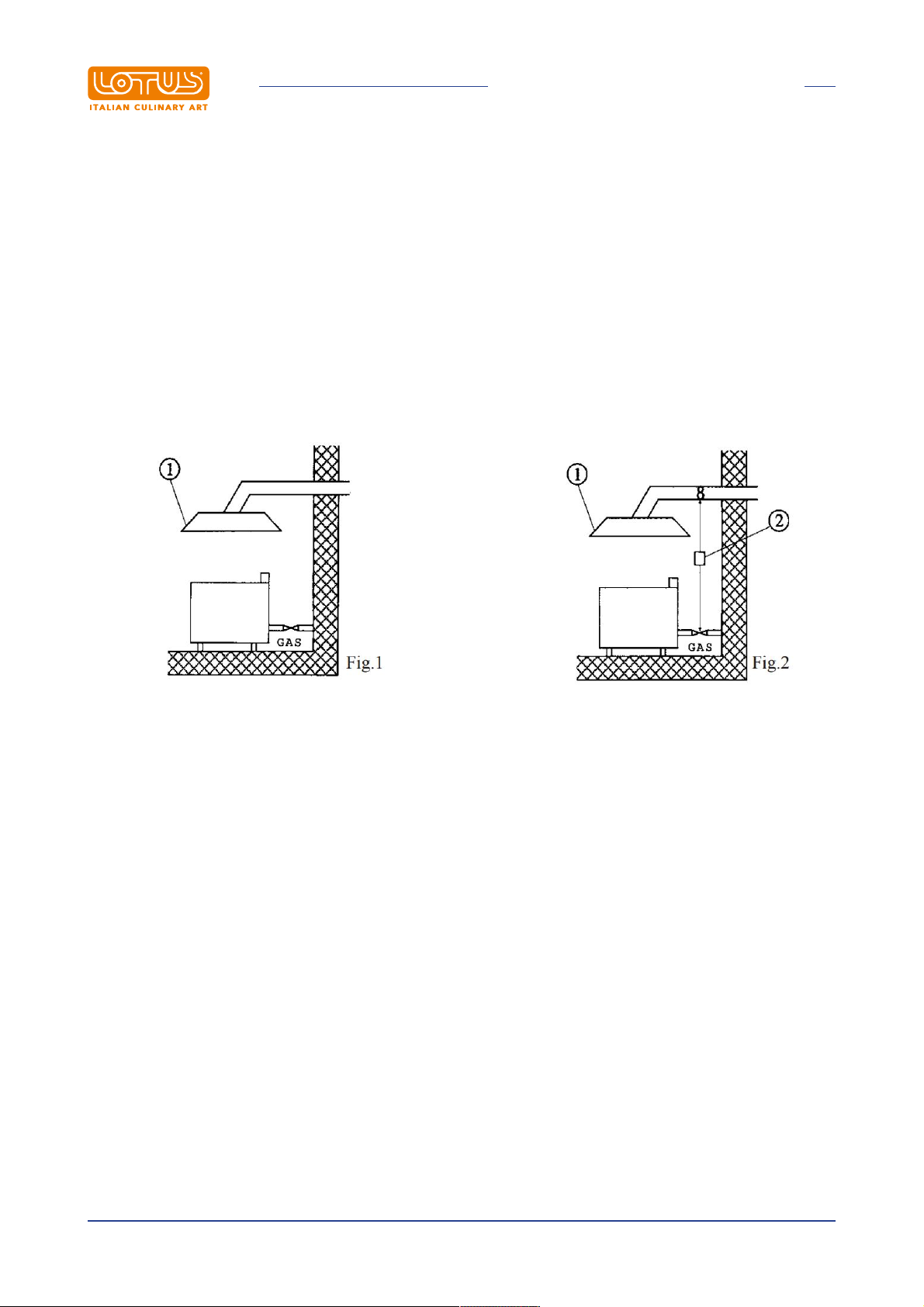
- "A" type devices (see data plate)
"A" type appliances must discharge combustion products into appropriate hoods, or similar devices,
connected to an efficient fume stack or directly to the outside. (Natural evacuation) Fig. 1
If this is not possible, using an air suction device connected directly to the outside is permitted (Forced
Evacuation) Fig.2, having a flow capacity not lower than the value defined in point 4.3 of the UNI-CIG 8723
standard.
- In the case of forced evacuation
The gas supply to the appliance must be directly servo-controlled by the system and must stop if the flow
rate drops below the values indicated in point 4.3 of the UNI-CIG 8723 standard. Resetting the gas supply to
the appliance must be possible only by hand.
1 Extractor hood
2 Servo system
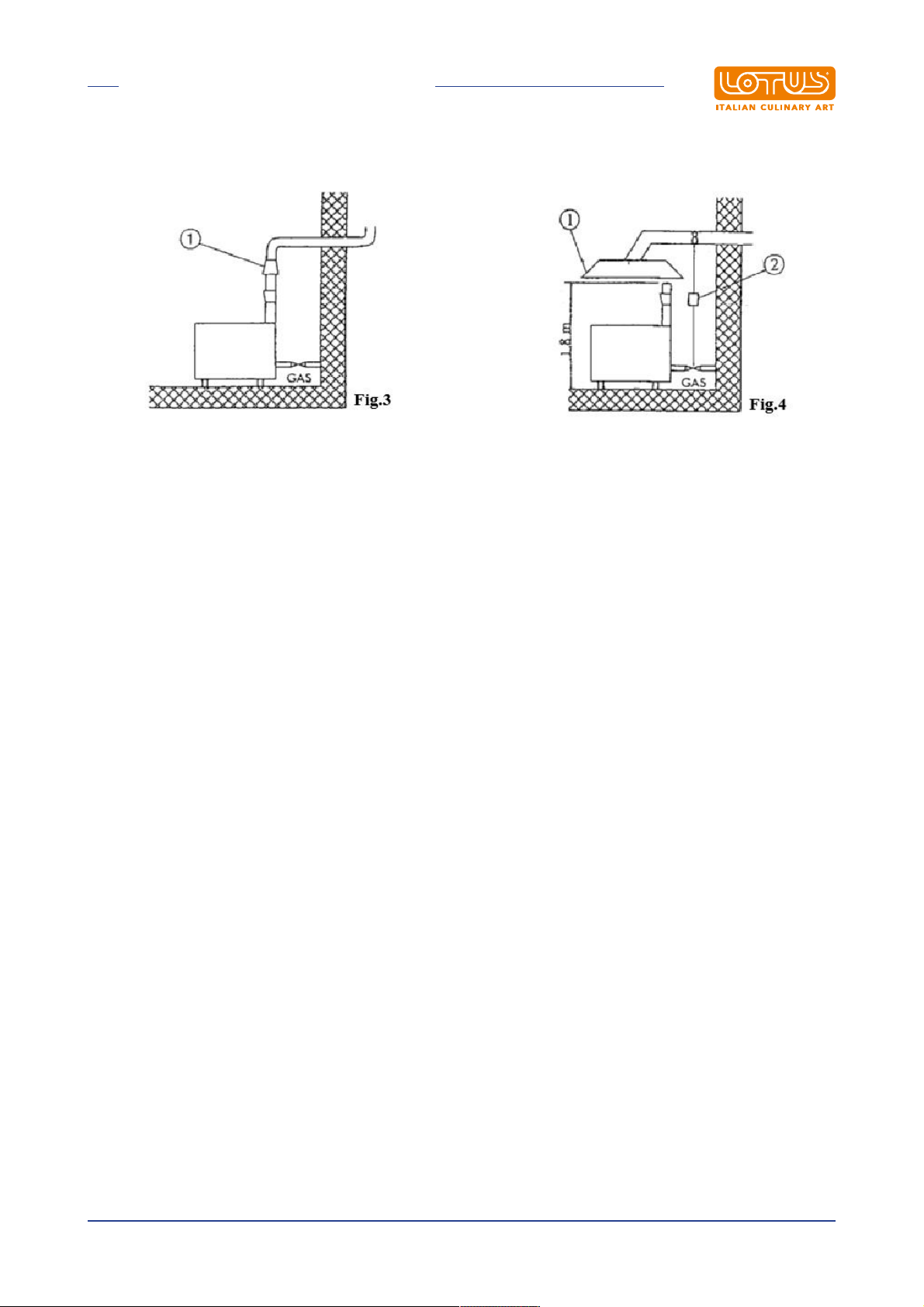
- "B11" type devices (See data plate)
Natural evacuation (fig.3)
Connection to an efficient natural draft fume stack by means of a windproof connection, with discharge of
combustion products directly to the outside
Forced evacuation (fig.4)
The gas supply to the appliance must be directly servo-controlled by the forced evacuation system and must
stop if the flow rate drops below the values indicated in point 4.3 of the UNI-CIG 8723 standard. Resetting
the gas supply to the appliance must be possible only by hand. If the installation is under a hood, the
terminal part of the appliance's exhaust pipe must be at least 1.8 meters from the appliance's support
surface (ground). The outlet section of the exhaust pipes for combustion products must be placed within the
perimeter in relation to the hood itself.
Instructions in original language
20
Page 21
INSTALLATION
1 Windproof fume stack (fig.3) - Extractor hood (fig.4)
2 Servo system
"B11" type appliances are supplied on request with a hood or a hood and windproof fume stack to be
assembled and delivered separately.
Instructions in original language
21
Page 22
BURNERS TECHNICAL DATA TABLE (ITGB)
4 BURNERS TECHNICAL DATA TABLE (ITGB)
4.1 Burners technical data table
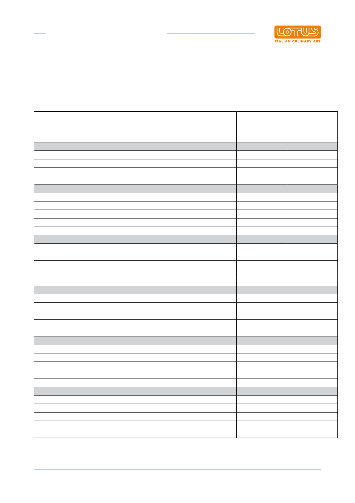
Technical data table - Burners TP S90G
12.68 kWh/KG
G30
BUTANE
30 mbar
Burner TP max 7 kW - min 4 kW
Burner injector 1/100 mm 130A 130A 195
Minimum adjustment 1/100 mm 100 100 100
Pilot injector 1/100 mm 19 19 27
Consumption kg/h 0.552 kg/h 0.544 m3 st./h 0.740
Burner max 4 kW-min 1.5 kW
Burner injector 1/100 mm 95 95 145
Minimum adjustment 1/100 mm 60 60 adjustable
Pilot injector 1/100 mm 20 20 35
Consumption kg/h 0.313 kg/h 0.313 m3 st./h 0,423
Primary air h = mm 3 3 0
Burner max 7 kW - min 1.8 kW
Burner injector 1/100 mm 130 130 195
Minimum adjustment 1/100 mm 65 65 adjustable
Pilot injector 1/100 mm 20 20 35
Consumption kg/h 0.547 kg/h 0.547 m3 st./h 0.740
Primary air h = mm open open 1
Burner max 10 kW - min 2.3 kW
Burner injector 1/100 mm 155 155 230
Minimum adjustment 1/100 mm 75 75 adjustable
Pilot injector 1/100 mm 20 20 35
Consumption kg/h 0.789 kg/h 0.777 m3 st./h 1.058
Primary air h = mm open open 1
Oven burner max 8.5 kW-min 2.2 kW
Burner injector 1/100 mm 145 145 220
Minimum adjustment 1/100 mm 75 75 adjustable
Pilot injector 1/100 mm 19 19 27
Consumption kg/h 0.670 kg/h 0, 660 m3 st./h 0.899
Primary air h = mm 20 20 20
Oven burner max 13 kW - min 3.5 kW
Burner injector 1/100 mm 180 180 290
Minimum adjustment 1/100 mm 100 100 adjustable
Pilot injector 1/100 mm 19 19 27
Consumption kg/h 1.025 kg/h 1.010 m3 st./h 1,376
Primary air h = mm 25 25 25
12.87 kWh/KG
G31
PROPANE
37 mbar
9.45 kWh/m3st.
G20
METHANE H
20 mbar
Instructions in original language
22
Page 23
INSTRUCTIONS FOR USE
5 INSTRUCTIONS FOR USE
5.1 General information
This appliance must only be used for its expressly intended purpose for cooking or heating food. Any other
use is considered improper. The appliance is also intended for industrial use and must only be used by
personnel trained for use and aware of the risks that the hot element entails.
Warning
The appliance operates at high temperatures, so the following is necessary:
· Pay attention to the areas surrounding the hot surface during routine normal operation
(danger of scalding);
· RISK OF BURNS Do not touch hot surfaces floor with your hands or other parts of the body
to avoid burns caused by high temperatures;
· After switching off the appliance, wait for a sufficient time for it to cool before carrying out
any cleaning or maintenance operation.
5.2 Lighting and adjusting the open rings
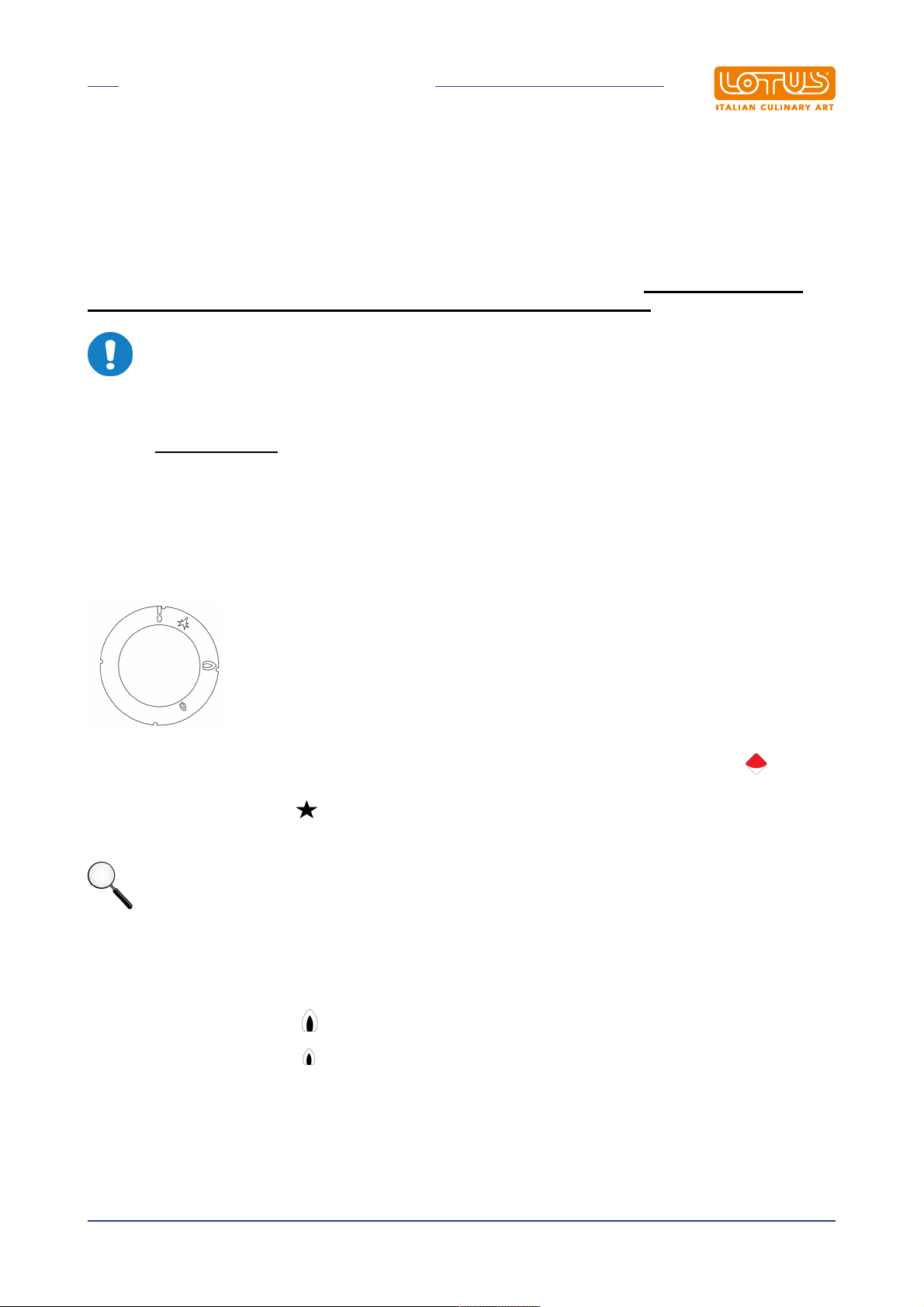
The corresponding burner marked on the index is indicated above each knob on the front panel
· Place gas knob in position and hold it pressed for a few seconds. Simultaneously, move an igniter
close to the pilot to ingite it
Note
The flame might go out, in which case the procedure must be repeated.
5.3 Starting the main burner and adjusting the temperature
· Turn the knob into position to set the burner to maximum
· Turn the knob into position to set the burner to minimum
Instructions in original language
23
Page 24
INSTRUCTIONS FOR USE
5.4 Switching the main burner off
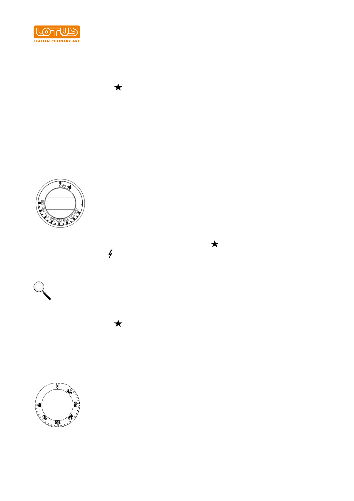
· Turn the knob into position . The burner turns OFF and only the pilot flame remains ON
5.5 Turning the appliance off
· Press and turn the gas cock knob to position "0". This control blocks the gas supply to both the main
burner and the pilot burner
5.6 Lighting and regulating gas oven burner
To switch ON, turn the knob to the left from the "0" position into the position; hold the knob pressed and
activate the button with the symbol until the pilot lights up
· Ignition of the flame can be checked through the inspection hole on the bottom of the oven
Note
The flame might go out, in which case the procedure must be repeated.
· Set the knob to the desired temperature position
· Turn the knob into position . The burner turns OFF and only the pilot flame remains ON
· Press and turn the gas cock knob to position "0". This control blocks the gas supply to both the main
burner and the pilot burner
5.7 Turning on and adjusting the static oven
· Turn the control knob to the right and set the desired temperature
Instructions in original language
24
Page 25
INSTRUCTIONS FOR USE
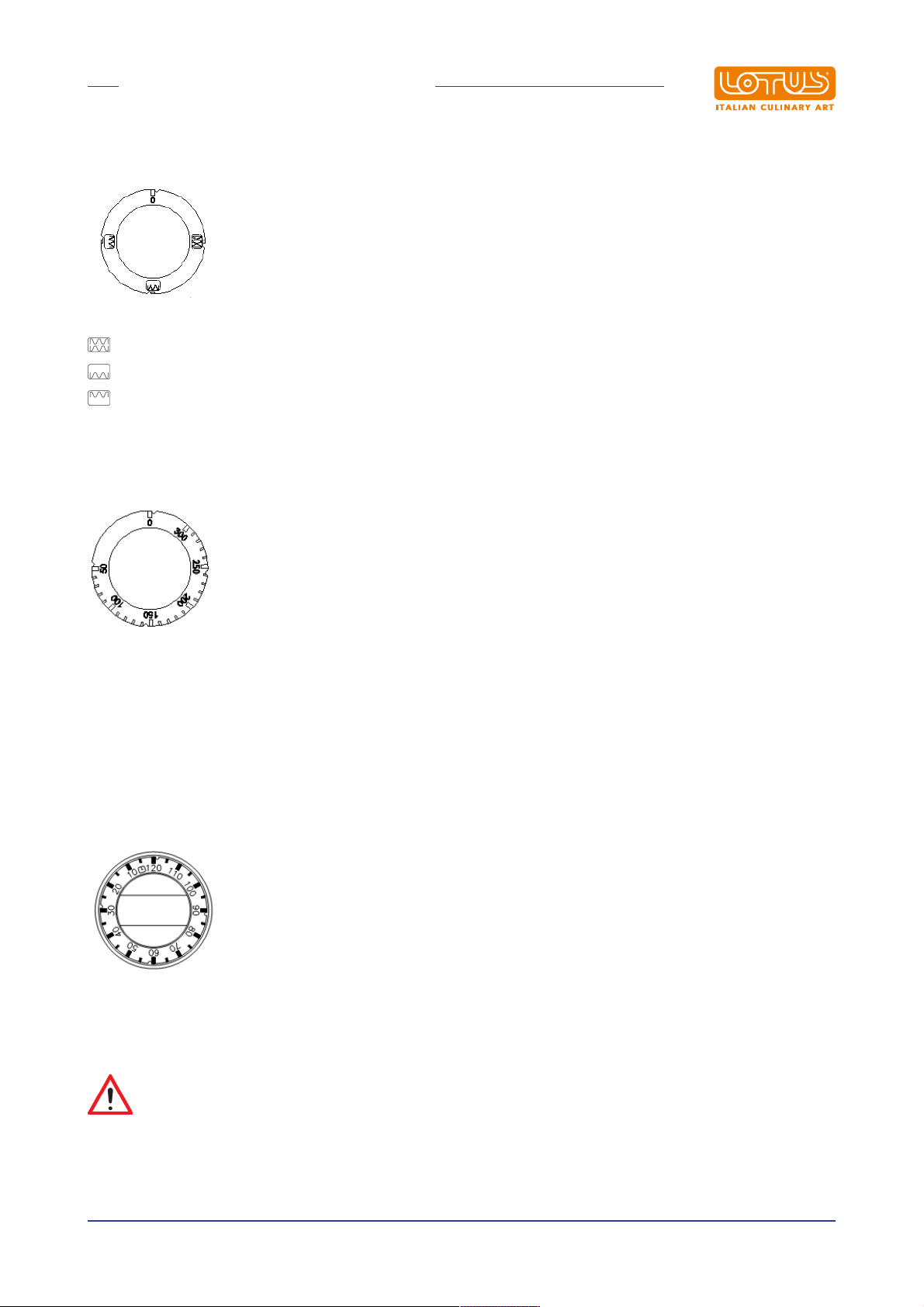
· Also turn the knob of the selector, setting one of the three positions
Top + bottom heating element
Bottom heating element
Top heating element
5.8 Turning on and adjusting the fan oven
The hot air put in circulation by the fan is distributed in the entire oven chamber, ensuring even cooking. The
uniform heating of the chamber makes it possible to cook different foods at the same time on different levels.
Turn the knob on the panel from “O” to the desired position between 50° and 300°C, the white and green
indicator lights will turn on
· The green indicator light indicates that the appliance is powered
· The white indicator light indicates that the heating element is functioning and when it turns off, this means
that the temperature has been reached. Turn the knob to “O” to switch off the appliance
MECHANICAL TIMER
The cookers have an acoustic timer that can signal a maximum time of 120 minutes. Turn the knob to the
right, position it to the preselected time, between 0 and 120 minutes (see figure); once the set time has
elapsed, the acoustic timer activates
Caution
When the oven is operating, the door must not remain open as it could overheat and damage
the knobs and the protective plates
Instructions in original language
25
Page 26
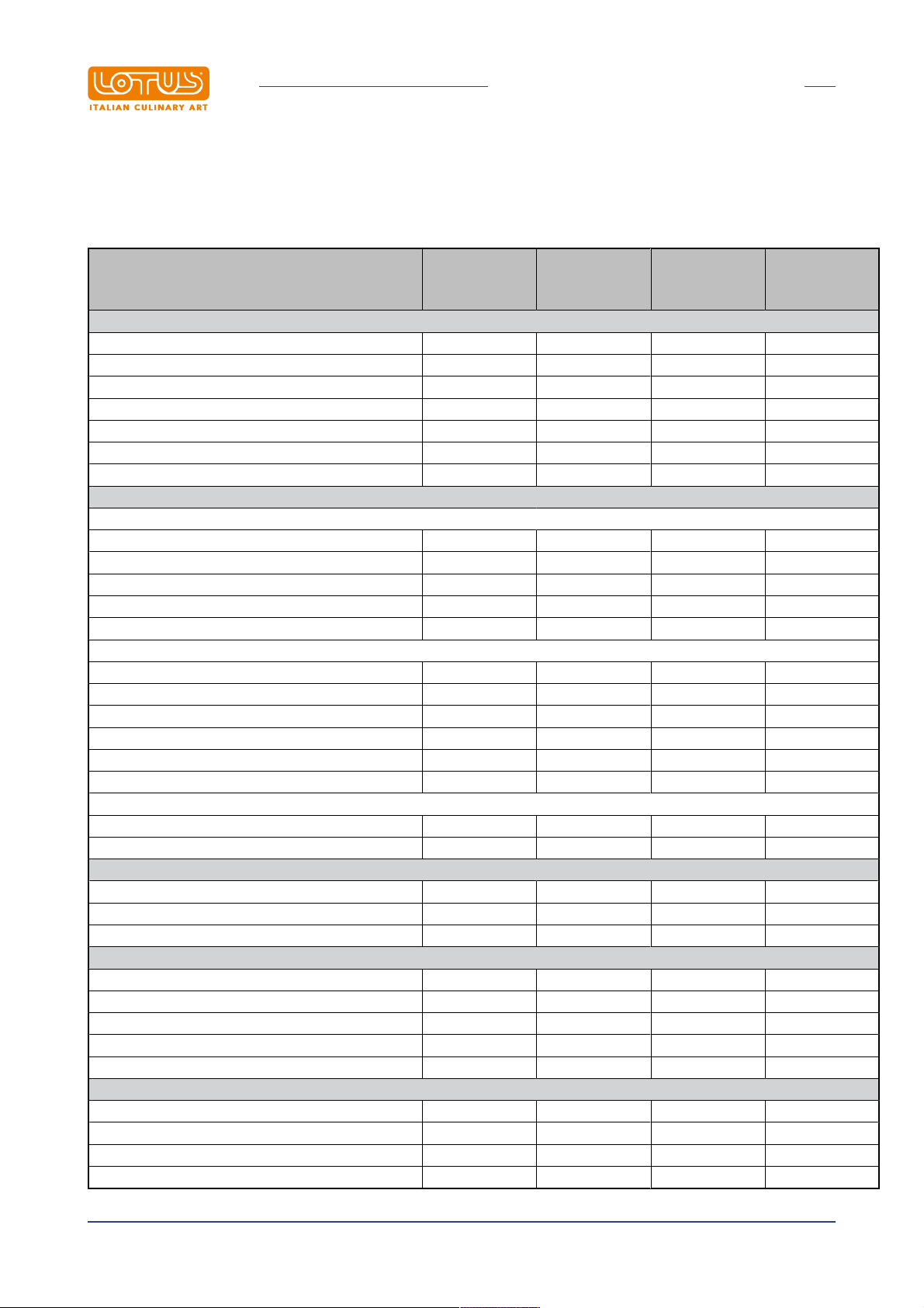
5.9 Cooking table for the fan oven
Ventilated electrical oven cooking table
INSTRUCTIONS FOR USE
Guide no.
Type of food
from the
Quantity Kg
bottom
Sweets
With a beaten dough, in a mould 1-3 1 175 60
With a beaten dough, without a mould 1-3-4 1 175 50
Shortcrust pastry, cake base 1-3-4 0,5 175 30
Shortcrust pastry with moist filling 1-3 1,5 175 70
Shortcrust pastry with dry filling 1-3-4 1 175 50
With natural leavened pastry 1-3 1 175 50
Small sweets 1-3-4 0,5 160 30
Meat
Roasts cooked on the grill
Veal 2 1 180 60
Beef 2 1 180 70
Roast beef 2 1 220 50
Pork 2 1 180 70
Chicken 2 1-1,5 200 70
Roasts cooked in the pan
Veal 1-3 1 160 90
Beef 1-3 1 160 90
Pork 1-3 1 160 90
Chicken 1-3 1-1,5 180 90
Turkey slices 1-3 1,5 180 120
Duck 1-3 1-1,5 180 120
Stews
Beef stew 1 1 175 120
Veal stew 1 1 175 110
Fish
Fillets, steaks, cod, hake, sole 1-3 1 180 30
Mackerel, turbot, salmon 1-3 1 180 45
Oysters 1-3 1 180 20
Baked dishes
Baked pasta 1-3 2 185 60
Baked vegetables 1-3 2 185 50
Sweet and salty soufflés 1-3 0,75 180 50
Pizzas and calzones 1-3-4 0,5 200 30
Toast 1-3-4 0,5 190 15
Defrosting
First courses 1-3 1 200 45
Meat 1-3 0,5 50 50
Meat 1-3 0,75 50 70
Meat 1-3 1 50 110
Temperature°CMin. cooking
time
Instructions in original language
26
Page 27

INSTRUCTIONS FOR USE
Note
· The indication of use of the levels shown in the table is recommended when cooking on multiple
levels
· The indicated times refer to cooking on only one level. Add 5-10’ when cooking on multiple levels
· Add 20' for beef, veal, pork and turkey roasts with bones or for meat rolls
· The cooking times can vary depending on the type of food, their homogeneity and their volume
· Before cooking for the first time, select the lower value of the temperature setting range indicated in
the table
· The cooking time will be extended based on the lower heat
Instructions in original language
27
Page 28

MAINTENANCE
6 MAINTENANCE
6.1 Routine
When using the appliance over time, it is essential to perform regular maintenance to ensure safe operation.
We therefore recommend stipulating a service contract.
Caution
Maintenance must only be performed by specialist personnel in compliance with current
Before carrying out any maintenance and/or cleaning operation:
· Disconnect the appliance from the mains power supply and/or close the gas.
· Wait for a sufficient time for the appliance to cool down.
· Do not wash the appliance with direct or high-pressure jets of water, since any infiltration of water into the
Replacing parts must exclusively be performed by authorised and/or qualified personnel. When replacing the
electrical components of the machine and the electrical panels, scrupulously follow the technical
characteristics for the replacement component indicated on the component itself. The appliance does not
require any special maintenance but during the use of the equipment it is advisable to check the following at
least once a year (possibly increasing the frequency depending on the degree of use):
· The status of connections especially on the terminal board and the power supply cable, as well as the
· The operating condition of the various components (perform a functional test);
· For appliances fitted with rotary resistances, remove the hub, grease it and replace the three o-ring seals
regulations and our own instructions.
electrical components could jeopardise correct operation of the appliance and its safety systems.
Warning
For maintenance/replacement of components, order and use only original spare parts.
status of the gas connections;
to avoid possible leaks.
6.2 Changing the open ring nozzles (fig. C)
· Remove the grills, burners and pans. Use 12 wrench to replace the nozzles with the appropriate ones
and adjust the primary air (h) (see the "burners" technical data table) by unscrewing the locking screw
· After setting the adjustment, lock the screw, set the minimum by turning the screw to the right or left until
heat reaches 1.5 kW for the 4 kW burner, 1.8kW for the 7 kW burner and 2.3 kW for the 10 kW burner
6.3 Substituting the nozzle in the pilot burner (fig. D)
· Remove the grills, burners and pans; using an 8 wrench loosen the nozzle holder and an 11 wrench to
unscrew the bottom of the nozzle holder, use a slotted screwdriver unscrew the pilot nozzle and replace it
with an appropriate one, tightening it fully
· Reassemble everything and adjust the air using the adjusting bushing until the pilot flame is steady and
has an intense blue colour
Warning
Instructions in original language
28
Page 29

MAINTENANCE
After conversion to another type of gas, update the technical data plate to indicate the type of
gas for which the appliance has been converted.
6.4 Substituting the nozzle in the oven burner
· Remove the base of the oven
· Unscrew the screws securing the burner nozzle guard
· Replace the nozzle using a suitable wrench (see the "burners" technical data table)
· · Set the air adjustment bush to the corresponding value in the "technical data" table by unscrewing the
locking screw complete with locknut, adjust the minimum by turning the screw to the right or left until the
heat output is 2.2 kW for the 8.5 kW burner, 3.5 kW for the 13 kW burner. This procedure is only possible
after having operated the oven burner for no more than about 20 minutes (knob in pos.300)
· After completing this procedure, refit the burner nozzle guard
· Use an appropriate wrench to replace the pilot nozzle
· After the adjustment, check ignition at maximum and minimum settings. Make sure that the flame, on
passing rapidly from maximum to minimum, does not present problems and that it does not go out after
closing or opening the oven door quickly
6.5 Minimum setting
· After conversion to use another type of gas, or if a flame is too high when the knob is in position (
small flame), adjust the minimum setting by turning the by-pass screw. For operation with LPG, the
by-pass must be completely closed; for operation with natural gas, it must first be closed and then
opened by 1/4 turn
6.6 Spare parts
It is possible to replace parts such as the gas tap, thermocouple, spark plug or the gas pipes simply and
quickly.
To replace such parts, proceed as follows:
· GAS TAP: after disassembling the front panel, unscrew the gas connection screw couplings, remove the
coupling, replace the faulty parts and install the new ones in sequence
· THERMOCOUPLE: unscrew the pilot burner coupling, unscrew the gas tap coupling in the same way
and replace the element
· SPARK PLUG; unscrew the coupling, remove the damaged one and replace it.
Caution
WHAT TO DO IN THE EVENT OF FAULTS:
Close the gas connection cock and/or switch off the power using the up-line device. Notify
customer service.
Warning
MEASURES TO BE TAKEN IF THE APPLIANCE IS NOT TO BE USED FOR A LONG TIME:
Close the gas cock and/or disconnect the power supply. Clean the system as specified above.
Instructions in original language
29
Page 30

CLEANING
7 CLEANING
7.1 Routine cleaning
Caution
The use of flammable fluids to clean the appliance is forbidden
To ensure hygiene and the durability of the appliance, perform external cleaning on a regular basis, taking
care not to damage the cables and the electrical connections. Before starting cleaning, disconnect the
appliance from the power supply. Parts in steel can be washed with warm water and a neutral detergent:
Rinse them thoroughly to eliminate all traces of detergent and then dry with a dry cloth. Do not use abrasive
and corrosive detergents. Enamelled parts must be washed with soapy water. For appliances that included
an oven, cleaning it is made easier by removing the support grid. Thorough, daily cleaning prevents faults
and accumulated deposits of fat and/or food. The steels used in the manufacture of professional equipment
are tried and tested materials of the highest quality. Thanks to their characteristics, they are ideal materials
for use with food substances.
Consequently, when using stainless steel appliances, the following suggestions must be observed:
· Stainless steel surfaces must always be kept clean, also ensuring contact with the air. The lack of oxygen
under layers of scale, starch, egg white or other deposits means that surfaces can be affected by
corrosion
· Do not use products containing salt or sulphuric acid to remove scale. Suitable products are available
commercially but a diluted solution of acetic acid can also be used
· To clean STAINLESS STEEL appliances, it is advisable to use detergents specifically formulated for this
material. For "minor cleaning", a mild washing up liquid solution may also be used
· Do not wash the appliance with jets of water under pressure
· Avoid using detergents containing abrasive powders or bleaches of any kind
· Lockable stainless steel appliances, during periods of inactivity, must be left uncovered so that air can
freely access internal metal surfaces
· Stainless steel must not remain in contact for long periods with concentrated acids or with aromatised
concentrates such as salt solutions, mustard, spice mixtures or the like. At certain temperatures and
concentrations, these substances can damage the passive layer. Contact surfaces must therefore be
immediately rinsed with clean water and then dried
· It is inadvisable to use stainless steel pots exclusively to cook foods in salt water (pasta, rice, potatoes,
etc.). From time to time, these pots must also be used to cook foods containing fats or vegetables. This
helps to prevent damage caused by corrosion
· After cooking foods in salt water, rinse the tanks with fresh water since salt water residues from cooking
form layers of highly concentrated saline solution that can cause spotting corrosion
· To prevent so-called secondary corrosion, prolonged contact of stainless steel with ferritic steels should
be avoided
· Any secondary corrosion spots must be eliminated immediately
· Do not use sharp objects that may scratch stainless steel parts and consequently give rise to
deterioration
Instructions in original language
30
 Loading...