

Page 1

Page 1
Lotus Service Notes Exige S/C
SUPPLEMENT
EXIGE SUPERCHARGED (S/C)
Sub-Section Page
Concept & Overview Exige S/C.# 2
Technical Data
Exige S/C.TD 3
Body
Exige S/C.B 4
Front Suspension
Exige S/C.C 5
Rear Suspension
Exige S/C.D 5
Engine
Exige S/C.E 5
Wheels & Tyres
Exige S/C.G 11
Brakes
Exige S/C.J 11
Cooling
Exige S/C.K 11
Maintenance & Lubrication
Exige S/C.O 12
Clutch
Exige S/C.Q 12
Miscellaneous Exige S/C.Z 12
sn_Exige Supercharged supplement.indd 1 03/03/2006 11:32:33
Page 2
Lotus Service Notes Exige S/C
Page 2
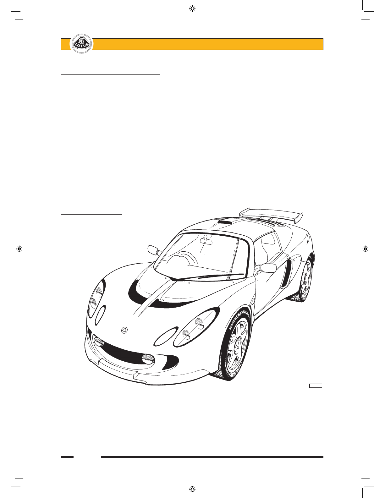
Lotus Sport Exige 240R
EXIGE S/C.# - CONCEPT & OVERVIEW
In February 2005, Lotus announced the Lotus Sport Exige 240R (243 bhp) to provide discerning customers
with an exclusive very high performance derivative of the Exige, to be built in a global limited edition of 50 units.
The cars to be produced to customer order as post registration official factory conversions of the '05 Exige by
the Lotus Sport workshops at Hethel, and available for the U.K. and certain overseas territories where regula
tions allow. In November 2005, Lotus Sport commenced build of a limited number of Exige Cup 240 cars in
road or race specification for selected markets, and differing in detail to the 240R. Then in January 2006, an
official production version of the supercharged car, Exige S, was introduced with a simplified specification.
The performance of the standard Exige is uprated by the fitment of a Magnuson supercharger belt driven
from the crankshaft, feeding through an air/air chargecooler into a new plenum/intake manifold, and featuring a
supercharger integral by-pass valve. The 240R engine uses a mechanical throttle and a 5th injector mounted
in the intake manifold plenum, whereas the '06 M.Y. Cup cars use an electronic throttle, larger port injectors
and no 5th injector, and the Exige S utilises standard injectors.
Chassis dynamics on 240R and Cup cars are uprated by the fitment of Ohlins 2-way adjustable dampers,
with adjustable spring platforms for the uprated springs, and new lightweight forged 5-spoke roadwheels of
slightly wider section to accommodate optional track use only slick tyres.
This supplement describes the features of the supercharged variants which differ from the standard '05
Exige model. For information on any subject matter not included here, refer to the main manual.
240Rint
sn_Exige Supercharged supplement.indd 2 03/03/2006 11:32:34
Page 3

Page 3
Lotus Service Notes Exige S/C
EXIGE S/C.TD - TECHNICAL DATA
Where different to standard Exige:
Engine
Forced induction Magnuson MP62 supercharger with
integral by-pass valve.
Air/air chargecooler.
Maximum boost pressure 0.5 bar (7 psi)
Max. power - 240R & Cup 181 kW (243 bhp; 247 PS) @ 8000rpm
- Exige S 162.5 kW (218 bhp; 221 PS) @ 7800rpm
Max. torque - 240R & Cup 236 Nm (174 lbf.ft; 24 kgf.m) @ 7000rpm
- Exige S 215 Nm (158.6 lbf.ft; 22 kgf.m) @
5500rpm
Power to weight ratio - 240R & Cup 195 kW/t (261 hp/t; 266 PS/t)
Specific power output - 240R & Cup 100.78 kW/l (136.97 hp/l; 137.4 PS/l)
Lubrication system supplement - 240R & Cup Accusump oil storage reservoir
Oil cooling Twin front mounted oil coolers
Wheels & Tyres
Wheels - type - 240R Lightweight forged alloy 5-spoke, satin
black or high power silver
- size - front - 240R 7J x 16
- rear - 240R 8J x 17
Suspension
Ride height, mid laden, front/rear - 240R & Cup 120/120 (2 x 75 kg pass., ½ tank fuel)
Spring rate - front - 240R & Cup 325 lb/in
- rear - 240R & Cup 425 lb/in
Front anti-roll bar - 240R & Cup 5-position adjustable
Dampers - 240R & Cup Ohlins gas pressurised with remote
reservoirs, 2-way damper adjustment,
adjustable spring top platforms.
sn_Exige Supercharged supplement.indd 3 03/03/2006 11:32:34
Page 4

Lotus Service Notes Exige S/C
Page 4
EXIGE S/C.B - BODY
Exterior
All 50 of the 240R cars are finished in high metallic content paint in either Sport Yellow or Sport Black,
reflecting the brand colour scheme of Lotus Sport. Yellow cars are complemented by black roadwheels, and
black cars with high power silver wheels.
A Lotus Sport 240R decal is applied to the RH side of the rear transom.
Paint Codes:
Sport Yellow: Lotus code B112 Du Pont code X3454
Sport Black: Lotus code B111 Du Pont code X3453
240 Cup and Exige S models were offered in the complete range of colours with the front splitter, side
intake scoops and the rear aerofoil (excluding support struts) finished in body colour rather than satin black.
Exige S cars feature an 'Exige S' decal on the rear trabnsom, and an 'S' decal on each fron quarter panel. Both
decals available in grey or silver dependent on body colour.
The chargecooler air intake scoop on the roof of Exige S models is fitted with an enlargement funnel mouth
(without grille) for increased airflow and enhanced chargecooler efficiency.
Interior
Each Lotus Sport Exige 240R is individually numbered from 001 to 050, and identified by a Lotus Sport
build plate styled after those used by Team Lotus for the Formula One cars. The plate is riveted to the chassis
main side rail on the passenger side, and is engraved with the unique Limited Edition number.
The 240R features black leather sports seats embroidered on the head restraints with Exige branding in
yellow, with further Lotus Sport yellow highlights on the seat sides, door trim inserts, gear lever gaiter and parking brake lever gaiter. Cup cars use black leather/suede/carbon effect trim with '06 M.Y. Probax sports seats.
240R and Cup cars are fitted with four point seat belt harnesses, with the shoulder straps anchored to a
seat belt mounting frame (roll hoop) cross bar. The roll hoop and back stays on these cars are manufactured
in T45 steel to allow easy conversion to U.K. motorsport MSA approval by the addition of an 'A' frame and
diagonal brace.
All 240Rs are equipped with air conditioning, but is optional on other models.
sn_Exige Supercharged supplement.indd 4 03/03/2006 11:32:34
Page 5

Page 5
Lotus Service Notes Exige S/C
EXIGE S/C.C - FRONT SUSPENSION - 240R & CUP
Stiffened road springs front and rear are fitted on new Ohlins dampers featuring remote gas reservoirs,
adjustable spring platforms and separate adjustments for compression and rebound damping. The spring plat
forms allow for lowering of the car to 120/120mm mid-laden ride height for track use, and the 22 compression
and 60 rebound damper settings allow the characteristics to be fine tuned to individual requirements. The gas
reservoir is mounted on the inboard crossbrace of the lower wishbone, and is connected to the damper body
by a steel braided hose.
Compression (bump) damping is adjusted by turning the knob on the end of the gas reservoir canister: Turn
clockwise to increase damping, and couterclockwise to decrease. Recommended settings are as follows:
Road use: 11 clicks from full hard
Track use: 11 clicks from full hard
Rebound damping is adjusted via a ribbed collar below the bottom spring seat: Turn clockwise (as viewed
from below) to increase damping, and counterclockwise to decrease. Recommended settings are as follows:
Road use: 8 clicks from full hard
Track use: 8 clicks from full hard
The motorsport stiffened and 5-position adjustable front anti-roll bar provides further opportunity for fine
tuning. To stiffen the bar, use a more forward hole, and to soften, use a more rearward hole. Recommeded
setting:
Road use: Central hole
Track use: Central hole
Suspension geometry is unchanged - refer to Section TDQ.
EXIGE S/C.D - REAR SUSPENSION - 240R & CUP
Stiffened road springs front and rear are fitted on new Ohlins dampers featuring remote gas reservoirs,
adjustable spring platforms and separate adjustments for compression and rebound damping. The spring
platforms allow for lowering of the car to 120/120mm mid-laden ride height for track use, and the 22 compres
sion and 60 rebound damper settings allow the characteristics to be fine tuned to individual requirements. On
240R models the gas reservoirs are mounted on the roll over bar backstays, and on Cup cars, on the toe-links.
Each reservoir is connected to its damper body by a steel braided hose.
Compression (bump) damping is adjusted by turning the knob on the end of the gas reservoir canister: Turn
clockwise to increase damping, and couterclockwise to decrease. Recommended settings are as follows:
Road use: 15 clicks from full hard
Track use: 10 clicks from full hard
Rebound damping is adjusted via a ribbed collar below the bottom spring seat: Turn clockwise (as viewed
from below) to increase damping, and counterclockwise to decrease. Recommended settings are as follows:
Road use: 15 clicks from full hard
Track use: 12 clicks from full hard
Suspension geometry is unchanged - refer to Section TDQ. The Track Use Chassis Rear Brace Kit is
fitted as detailed in sub-section DH.5.
EXIGE S/C.E - ENGINE
The 1.8 litre 2ZZ-GE engine with VVTL-i (Variable Valve Timing and Lift - intelligent) of the standard Exige
is fitted with a low pressure Roots type Magnuson MP62 supercharger to provide up to 0.5 bar (7 psi) of boost
pressure. The supercharger is mounted on the left hand side of the block and driven by a lengthened version
of the multirib auxiliary belt. The unit is self contained and features helix twisted rotors to minimise output
pressure variations, and maintenance free gearing and bearings, requiring no externally sourced lubrication.
An integral by pass valve under ECU control, operates to recirculate air from the compressor outlet back to the
inlet under conditions of idle and part throttle to the benefit of economy and quiet operation.
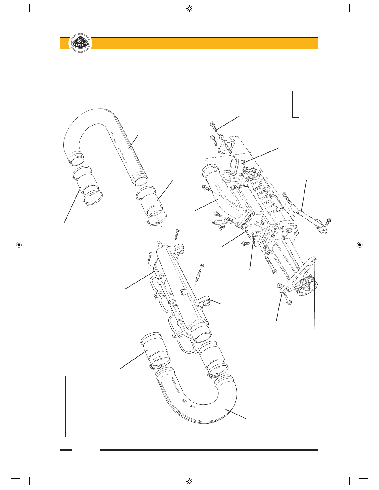
The supercharger is hung off the new intake manifold by two bolts in conjunction with eccentric sleeves in
order to ensure stress free alignment. An alloy bracket supports the nose of the unit to the RH engine mounting
plinth, and a tubular strut braces the intake end of the unit to the clutch slave cylinder mounting point.
sn_Exige Supercharged supplement.indd 5 03/03/2006 11:32:34
Page 6
Lotus Service Notes Exige S/C
Page 6
Supercharger & Ducting Connection to chargecooler inlet
Connection to chargecooler outlet
New inlet manifold
Chargecooler
inlet duct
Supercharger outlet connector
Supercharger outlet elbow
Supercharger
outlet adaptor
Mounting lug for
supercharger
Fixing point Swan neck
Chargecooler to manifold adaptor fixings
outlet duct (supercharger
inlet)
Fixed to engine
mounting plinth By-pass valve
capsule
pl4207ls/pl4209lr
Strut to clutch
Alternator anchor slave cylinder mounting
sn_Exige Supercharged supplement.indd 6 03/03/2006 11:32:35
Page 7
Page 7
Lotus Service Notes Exige S/C
Flexible bellows
Adaptor to chargecooler
Air duct
Chargecooler from roof
radiator scoop FRONT
Rubber mounting
Bracket to inlet manifold
and cam cover
Bracket to
inlet manifold
Fixing to inlet manifold
Rubber mounting
Chargecooler outlet duct Inlet manifold Chargecooler
Chargecooler
inlet duct
Boss
for 5th
injector Standard
(240R) airbox
Supercharger
outlet elbow
Supercharger
outlet adaptor
Electronic
Supercharger throttle body
FRONT Throttle body
adaptor
le2047a
pl4610aLR
sn_Exige Supercharged supplement.indd 7 03/03/2006 11:32:37
Page 8

Lotus Service Notes Exige S/C
Page 8
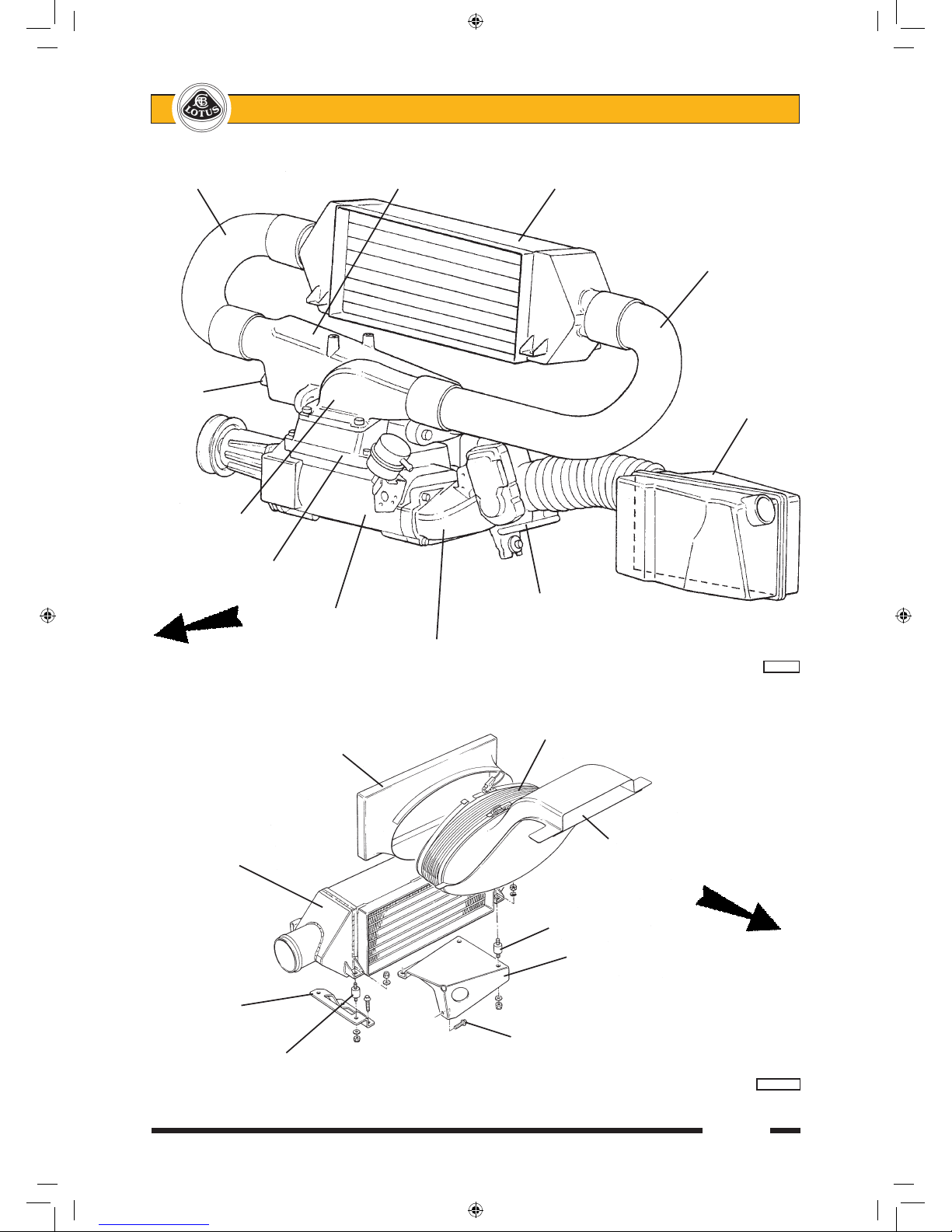
Air is drawn from the standard air cleaner through the throttle body and adaptor and into the supercharger
axial intake port. From the outlet port on the compressor top surface, the air is directed through a 'U' bend duct
to the LH end of an air/air chargecooler rubber mounted above the engine, where airflow gathered from the roof
duct is used to cool the compressed intake charge. The chargecooler uses four rubber bobbins attached to two
mounting brackets themselves secured to the inlet manifold and cam cover. A charge air temperature sensor
is mounted in the outlet tank of the chargecooler. The cooled air exiting from the RH end of the chargecooler
flows via another 'U' bend duct into a cast alloy intake plenum/manifold. The whole intake tract has been kept
as short as possible, and uses large diameter ducting and generously radiused bends to optimise airflow and
efficiency to the particular benefit of throttle response and fuel economy.
A re-shaped breather pipe is used to connect the crankcase breather spigot to the cam cover and circum
-
navigate the supercharger.
On the 240R and Cup cars, a stainless steel 'level one' sports exhaust muffler (LOTAC05334) is fitted to
provide an acoustic enhancement and features enlarged, slash cut tailpipes and a near 20% weight saving
over the standard system. Exige S models use a stainless muffler with a single, oval shaped, tailpipe design.
240R models use 4 standard port fuel injectors together with an additional 5th injector mounted in the
intake end of the inlet manifold. Cup cars use 4 special high-flow port injectors, and Exige S cars retain standard injectors. The Lotus engine management system is reprogrammed to suit each engine specification and
incorporates additional functions to control the fifth injector (240R) and supercharger by-pass valve. The boost
characteristics have allowed the switching point from low to high lift cam profile to be reduced from 6,000 to
4,000 rpm (at normal running temperature). 240R models use a mechanical cable operated throttle body,
whereas the Cup and Exige S cars use '06 model electronic throttle. Twin front mounted oil/air coolers are
fitted to all supercharged Exige.
Accusump - 240R & Cup 240
To provide protection against the possibility of oil starvation caused by the extreme g-forces possible with
track use on slick tyres, the 240R and Cup cars are fitted with an Accusump oil storage system.
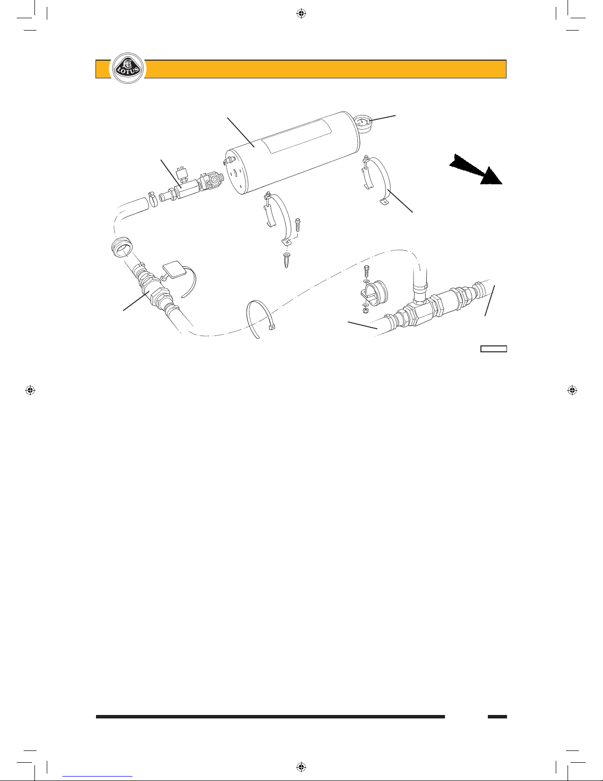
A 2-litre Accusump reservoir is mounted in the rear luggage compartment, plumbed into the LH oil cooler
return hose at the front of the engine bay, with the connecting hose routed over the RH rear wheelarch. The
device comprises an alloy cylinder divided by a sliding piston, one side of which is connected to the engine
oil supply, with the other containing pressurised air. With the engine running, the cylinder is charged with oil
provided by the engine oil pump, but if the pressure should drop for a short period due to oil pump pick up pipe
exposure during extreme braking or cornering events, the accumulator air pressure forces the stored oil into
the engine lubrication system to maintain continuity of oil supply until normal conditions are resumed.
A one-way valve at the oil cooler connection of the 'T'- piece ensures that the oil discharged from the
Accusump is directed into the oil pump and not the cooler. An Electric Pressure Control (EPC) valve fitted at
the connection to the Accusump cylinder, allows cylinder charging when oil pressure is above 35 - 40 psi, and
cylinder discharging at engine oil pressures below 35 - 40 psi. The EPC is also linked to the ignition switch
such that with the ignition switched on the valve is open to allow oil flow, and with ignition off the valve is closed
to retain oil within the reservoir.
Normal Operation
When the ignition is turned on, the EPC valve on the Accusump is opened, allowing the pressurised oil
stored in the reservoir to flow out into the engine and prime the oil galleries and bearings ready for start up.
When the reservoir has been emptied, the pressure gauge on the end of the reservoir will indicate the precharge pressure which should be 7 - 15 psi.
When the engine is started, engine oil pressure will force the reservoir piston back, such that the reservoir
air pressure gauge will indicate engine oil pressure, with the quantity of stored oil dependent on this pressure
at any one time. With cold oil, 80 psi may be seen, but idling at normal running temperature should produce
around 30 - 40 psi.
When the engine is stopped, the EPC valve closes and a quantity of oil pertaining to that oil pressure will
be retained in the Accusump, ready for re-starting.
Routine Checks
Be aware that the indicated oil level on the dipstick will depend on the amount of oil stored in the Accusump, which itself is dependent on the both the Accusump pre-charge air pressure and the engine oil pressure
when the ignition was switched off.
sn_Exige Supercharged supplement.indd 8 03/03/2006 11:32:37
Page 9
Page 9
Lotus Service Notes Exige S/C
Before checking the oil level, the Accusump pre-charge pressure should first be checked; turn on the
ignition to open the EPC valve and allow the stored oil to be discharged from the Accusump. The pressure
gauge reading will drop during this discharge, but should then register 7 - 15 psi representing the pre-charge.
If necessary, adjust the air pressure using tyre inflator equipment on the Schraeder valve adjacent to the gauge
and set to 15 psi.
The oil level should now be above the top mark on the dipstick. To check for correct oil level, the engine
should be started to charge the Accusump, and run to normal operating temperature until the Accusump pressure gauge registers 40 psi. If the engine is already hot, idle oil pressure may not be sufficient to open the
Accusump valve, and the pressure gauge will continue to show 15 psi pre-charge. Increase engine rpm to
open the valve. With the gauge showing 40 psi, turn off the engine. The EPC valve will then close and trap the
normal hot idle quantity of oil in the Accusump cylinder. After a suitable oil drainback pause, the sump oil level
may then be inspected on the disptick, and the level corrected to the top mark. It is important to maintain oil at
this level to accommodate the oil transfer into the Accusump at pressures greater than 40 psi. Be aware that
checking the oil level under any conditions other than 15 psi pre-charge and 40 psi oil pressure will produce
inconsistent results.
Oil Changing
Before draining the sump, the ignition should first be switched on to open the EPC valve and allow the
Accusump to discharge the stored oil into the sump. Check that a pressure of 7 - 15 psi remains in the Accusump at the end of this process, and if necessary top up the pressure using tyre inflating equipment on the
Schraeder valve next to the gauge and set to 15 psi.
The oil can then be drained in the usual way, with the quantity contained in the oil cooler lines disregarded
for the purposes of routine maintenance. If an engine failure has occurred, with possible debris contamination
of oil hoses and coolers, it is recommended to replace both oil coolers, and to replace or thoroughly flush the
feed and return hoses. At each service interval the in-line filter gauze in the hose between the Accusump and
'T'- piece, and located in the RH rear wheelarch, should be renewed.
After renewing and pre-filling the engine oil filter, refill the sump to about 10mm above the top mark on the
dipstick. Start the engine and allow to idle. Do NOT rev the engine or drive the car. The Accusump will take
up to 2 litres of oil from the sump to store within the cylinder. Continue to idle the engine until the Accusump
pressure gauge drops to 40 psi (as the oil warms) and then switch off the engine. Top up the oil to the top
mark on the dipstick.
Accusump reservoir Air pressure gauge
EPC valve
assembly
FRONT
Mounting clamp to
boot floor
In-line
filter To LH port From oil
on sandwich cooler
plate
pl4015cLR
sn_Exige Supercharged supplement.indd 9 03/03/2006 11:32:38
Page 10

Lotus Service Notes Exige S/C
Page 10
Supercharger Remove/Refit
To remove:
1. Remove the chargecooler together with inlet and outlet 'U' shaped ducts.
2. Remove the throttle body and vacuum/breather hose plumbing.
3. Using a 6-point socket, relieve auxiliary belt tension and remove the auxiliary belt. Remove the alternator
top mounting bolt, slacken the lower, and swing down the alternator. Release the dipstick tube from the
supercharger.
4. Using a strap wrench, remove the supercharger pulley retaining nut, and slide off the pulley.
5. Remove the support strut between the throttle body adaptor and the clutch slave cylinder. Slacken the
pinch bolt securing the supercharger to the nose bracket. Remove the two bolts supporting the super
-
charger to the inlet manifold and withdraw the supercharger.
To refit:
1. With the supercharger nose bracket bolted to the engine mounting plinth, fit the upper fixing on the alter
nator to the nose bracket outer end (with 13.5mm spacer). This defines the position of the nose bracket.
Tighten bracket to engine mounting plinth to 50 Nm. Remove alternator top bolt and swing down to allow
supercharger to be fitted.
2. Prepare supercharger: Clean mating faces of supercharger and outlet adaptor using Betaclean 3900. Fit
'O' ring into groove in outlet adaptor and fit to supercharger using 6 off M8 x 25 setscrews with Permabond
A130. On the fixing located inside the adaptor, Permabond should be applied over the entire thread length.
Orientate the adaptor with the outlet pointing towards the rear of the car when fitted. Torque tighten all
fixings to 25 Nm.
Clean mating faces of outlet adaptor and outlet elbow using Betaclean 3900. Fit 'O' ring into groove in
outlet adaptor face. Fit outlet elbow to point to LH side of car using 4 off M8 x 25 setscrews with a pipe
clip bracket secured by both rearmost fixings. Tighten to 25 Nm.
3. Fit M8 stud B111E6081S into RH top (as viewed on face) fixing position in supercharger inlet flange. Clean
mating face on supercharger and inlet adaptor using Betaclean 3900. Fit 'O' ring into groove in adaptor
face and fit adaptor to supercharger using 2 off M8 x 30 flange head bolts in top positions and M8 flange
nut on stud - all 25 Nm. Disregard 4th position at this stage.
4. Mount supercharger: With the pulley removed from the supercharger, slide the nose into the nose bracket
until hard against the machined step. Support to the inlet manifold sliding bushes using M10 x 50 flange
head bolts and Permabond A130, but do not tighten. Tighten the nose bracket socket head pinch bolt to
25 Nm.
5. Loosley fit the supercharger support strut between the inlet adaptor (M8 x 55 bolt with A130) and the clutch
slave cylinder fixings (M8 x 25 with A130). Tighten the three support strut bolts to 25 Nm. Carefully tighten
the two M10 x 50 flange head bolts to pull in the two spacers evenly to clamp against the supercharger.
6. Refit the alternator upper bolt and spacer and tighten to 25 Nm. Tighten the lower bolt to 25 Nm.
7. Fit the pulley to the supercharger with the longer boss towards the 'charger. Fit the nut onto the shaft, and
use a strap wrench to hold the pulley whilst the nut is tightened to 61 Nm.
sn_Exige Supercharged supplement.indd 10 03/03/2006 11:32:38
Page 11
Page 11
Lotus Service Notes Exige S/C
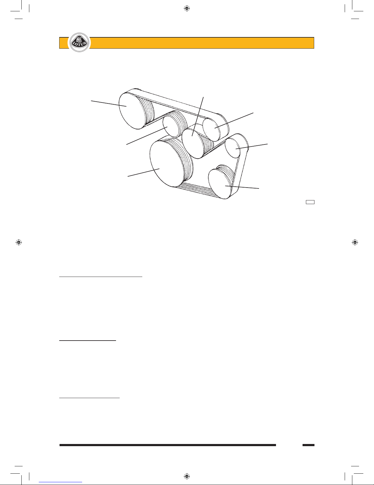
8. Use a 6-point socket on the tensioner arm to allow fitment of the multirib accessory drive belt around the
pulleys as shown, ensuring that the belt is correctly seated in all the ribbed pulleys.
9. Refit other components in reverse order to removal.
Note areas of change compared with standard models;
# Engine dipstick tube altered to avoid supercharger.
# Crankcase breather pipe altered to avoid supercharger.
# Relays on engine bulkhead move to avoid supercharger by-pass capsule
# Charcoal canister moved from bulkhead to bracket on top of chassis right hand rear upright member to
avoid alternator.
EXIGE S/C.G - WHEELS & TYRES
240R cars use lightweight forged alloy 5-spoke roadwheels at 7x16 and 8x17 are ½ inch wider, front and
rear, than standard Exige wheels, but retain the standard insets of + 31.3 mm and + 38.0 mm. The wheels
are finished in either Satin Black or High Power Silver dependent on body colour (see above). 'Lotus Sport' is
moulded into one of the spokes of each wheel. Cup and Exige S models use standard Exige wheels finished
in hi-power silver.
The Lotus specific, regular Exige Yokohama A048 tyres, identified by 'LTS', are fitted as standard.
EXIGE S/C.J - BRAKES
For 240R and Cup models, the braking system is uprated in the following respects:
- Motorsport brake pads are fitted front and rear;
- Steel braided brake hoses fitted all round;
- Front and rear brake callipers are finished in 'Sport Yellow';
- Hydraulic system filled with Castrol 'SRF' synthetic racing brake fluid. Over 500°F boiling point. Dot 4.
EXIGE S/C.K - COOLING
Twin front mounted oil/air coolers (std. Exige hot climate spec.) are fitted to all supercharged Exige mod
els. An engine intake air chargecooler radiator is rubber mounted to the engine, with cooling airflow collected
by the roof duct and directed via the tailgate panel and flexible bellows to the radiator, after which the hot air
exhausts through the tailgate louvres.
Water pump
Slave pulley
Supercharger
Belt tensioner Alternator
Crankshaft pulley
A.C.
compressor
e232
sn_Exige Supercharged supplement.indd 11 03/03/2006 11:32:38
Page 12

Lotus Service Notes Exige S/C
Page 12
EXIGE S/C.O - MAINTENANCE & LUBRICATION
A Maintenance Schedule for supercharged cars is available under part number LSL460b.
Recommended lubricants are unchanged apart from:
- 240R & Cup cars: Brake Fluid; Castrol SRF
- Fuel; Unleaded 98 RON
Spark plugs are part number ALS3E6015F (NGK PFR7G) with 0.8mm (- 0.1, + 0) gap.
EXIGE S/C.Q - CLUTCH
240R and Cup cars use an uprated clutch cover assembly and a competition specification sintered metal fric
tion plate. No routine maintenance is required other than annual renewal of the Castrol SRF hydraulic fluid.
EXIGE S/C.Z - MISCELLANEOUS
Supercharged models also differ from standard Exige in the following respects:
# Engine dipstick tube altered to avoid supercharger.
# Relays on engine bulkhead moved to avoid supercharger by-pass capsule.
# Charcoal canister moved from bulkhead to bracket on top of chassis right hand rear upright member.
sn_Exige Supercharged supplement.indd 12 03/03/2006 11:32:38
Page 13
Page 13
Lotus Service Notes Exige S/C
EXIGE S/C.X - RETROFITMENT OF SUPERCHARGER
To retrofit the Magnuson MP62 supercharger and related engine systems to the standard Exige, proceed
as follows. Note that throughout this section, the terms 'front', 'rear', 'left' and 'right' when referring to engine
components are used in the convention of the flywheel end of the engine being the rear. The orientation of the
engine as installed, results in the front of the engine being towards the right hand side of the car.
1. Remove the following parts:
- Drain coolant;
- Rear clamshell;
- Charcoal canister, bracket and pipes;
- Spark plug and injector covers;
- Convoluted air intake trunking;
- Throttle body;
- Fuel rail with injectors (keep together); Seal apertures with tape;
- Inlet manifold and moulded foam pads beneath; Seal apertures with tape;
- Breather pipe between crankcase and cam cover; Dipstick tube; Seal apertures with tape;
- Auxiliary drive belt and water pump pulley;
- Alternator top mounting bolt and stabiliser bracket, and swing alternator outwards;
- Engine wiring harness, ECM and mounting plate;
2. With the ECM mounting plate on a bench, mark out and cut the right hand top corner of the plate as shown.
Further cut and drill the removed section to the dimensions shown, and fix to the ECM plate with an M6 x
25 screw, penny washer and plain nut.
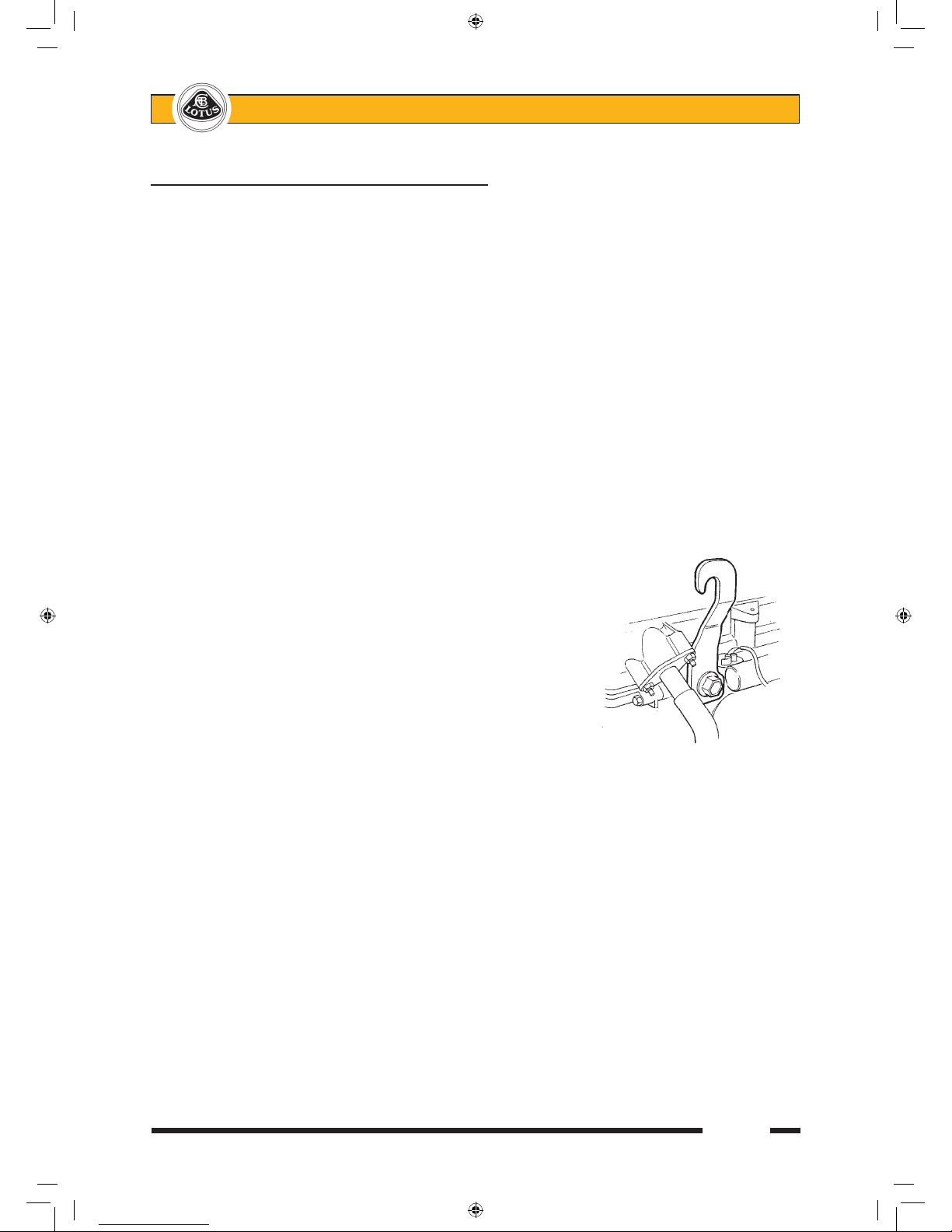
3. Fit an engine lifting hook T000T1437S to the LH front of the
cylinder head using bolt T000T1440S and support the engine
weight to allow the RH engine rubber mounting to be removed:
Remove the engine rubber mounting with pressed steel and
alloy brackets as an assembly.
4. To allow access to the rearmost fixing of the engine mounting plinth on the front of the engine, it is neces
sary to release the exhaust manifold and EGR pipe fixings: Remove the EGR pipe clip from the timing
chain cover. Remove the exhaust manifold upper heat shield. Remove the two outermost nuts retaining
the exhaust manifold. Slacken the remaining 3 manifold bolts.
Release the four bolts and remove the engine mounting plinth. Replace with the modified version using
original fixings, and with Loctite 5910 (A121L0077H) sealant applied to the fixing by the EGR pipe. Tighten
all four bolts to 52 Nm.
Refit exhaust manifold using Permabond A130 threadlock on the fixings and tighten to 52 Nm. Refit heat
shield using A130 and 20 Nm. Refit EGR pipe clamp to 27 Nm.
5. Remove the engine rubber mounting from the pressed steel bracket and replace with new rubber mount
ing ALS3E0038F (52 Nm). Refit the engine mounting assembly to the engine and chassis and remove
engine support equipment.
6. Remove and discard breather spout from LH side of crankcase, but retain connector hose. Fit new spout
using original fixings (10 Nm) and refit connector hose. Fit new breather pipe into connector hose and to
cam cover using original fixings. Fit new dipstick tube into position.
7. From inlet manifold jointface on cylinder head, remove and discard the long stud at the rear end of the
face. Fit new M8 x 25 stud (10 Nm) to the central fixing position between ports 2 and 3. Slacken the
screw securing the VVT valve to the LH front of the head to allow it to be re-orientated to clear the new
sn_Exige Supercharged supplement.indd 13 03/03/2006 11:32:39
Page 14

Lotus Service Notes Exige S/C
Page 14
manifold.
Fit the new manifold and retain with the original two top fixings using Permabond A130. Do not fully
tighten. Use new flange head bolt A116W5238F with Permabond A130 at the rearmost fixing point. Take
the nut previously fitted on the foremost stud, and fit instead to the new stud at the centre bottom fixing
(with Permabond A130). Take the nut previously fitted on the centre bottom stud, and fit instead to the
foremost stud using A130. Progressively tighten all fixings to 27 Nm. Secure the VVT valve to 10 Nm.
8. Lay the new engine harness in position with the injector portion in the channel between inlet manifold and
cylinder head with injector breakouts uppermost and aligned with the injector ports. Route the harness
between the new breather pipe and inlet manifold, following a tight line down beside the cylinder head
and block to the back of the alternator.
9. Refit the injector rail taking care to correctly seat the injectors. Ensure the spacers are in place before
securing with the 2 x M8 fixings - 20 Nm. Secure the fuel pipe to the cam cover - 9 Nm.
10. Remove the four coil packs and replace the spark plugs with the new PFR7G items. Torque to 18 Nm.
Refit coil packs to 9 Nm.
11. Refit all connectors on new harness.
12. Fit supercharger nose bracket to engine mounting plinth with new M10 x 50 flange head bolt and M10
flange nut hand tight. Fit upper fixing on alternator to nose bracket outer end using the 13.5mm spacer
and M8 x 55 flange head bolt. This defines the position of the nose bracket. Tighten bracket to engine
mounting plinth to 50 Nm. Remove alternator top bolt to allow supercharger to be fitted.
13. Prepare supercharger: Clean mating faces of supercharger and outlet adaptor using Betaclean 3900. Fit
'O' ring into groove in outlet adaptor and fit to supercharger using 6 off M8 x 25 setscrews with Permabond
A130. On the fixing located inside the adaptor, Permabond should be applied over the entire thread length.
Orientate the adaptor with the outlet pointing towards the rear of the car when fitted. Torque tighten all
fixings to 25 Nm.
Clean mating faces of outlet adaptor and outlet elbow using Betaclean 3900. Fit 'O' ring into groove in
outlet adaptor face. Fit outlet elbow to point to LH side of car using 4 off M8 x 25 setscrews with a pipe
clip bracket secured by both rearmost fixings. Tighten to 25 Nm. Fit double pipe clip into front side of
each of the two brackets.
14. Fit M8 stud B111E6081S into RH top (as viewed on face) fixing position in supercharger inlet flange. Clean
mating face on supercharger and inlet adaptor using Betaclean 3900. Fit 'O' ring into groove in adaptor
face and fit adaptor to supercharger using 2 off M8 x 30 flange head bolts in top positions and M8 flange
nut on stud - all 25 Nm. Disregard 4th position at this stage.
15. Fit original throttle body isolator to inlet adaptor using the clockwise choice of fitting position, with original
fixings tightened to 10 Nm. Fit the original throttle body to the isolator using original fixings tightened to
10 Nm.
16. Mount supercharger: With the pulley removed from the supercharger, slide the nose into the nose bracket
until hard against the machined step. Support to the inlet manifold sliding bushes using M10 x 50 flange
head bolts and Permabond A130, but do not tighten. Tighten the nose bracket socket head pinch bolt to
25 Nm.
17. Loosley fit the supercharger support strut between the inlet adaptor (M8 x 55 bolt with A130) and the clutch
slave cylinder new fixings (M8 x 25 with A130). Tighten the three support strut bolts to 25 Nm. Carefully
tighten the two M10 x 50 flange head bolts to pull in the two spacers evenly to clamp against the super
-
charger.
18. Refit the alternator upper bolt and spacer and tighten to 25 Nm. Tighten the lower bolt to 25 Nm.
19. Fit the pulley to the supercharger with the longer boss towards the 'charger. Fit the nut onto the shaft, and
sn_Exige Supercharged supplement.indd 14 03/03/2006 11:32:39
Page 15

Page 15
Lotus Service Notes Exige S/C
use a strap wrench to hold the pulley whilst the nut is tightened to 61 Nm.
20. Use a 6-point socket on the tensioner arm to allow fitment of the new multirib accessory drive belt around
the pulleys as shown, ensuring that the belt is correctly seated in all the ribbed pulleys.
21. Fit two rubber mountings to both of the chargecooler mounting brackets using spring washers and M8
Nyloc nuts. Fit the LH bracket to the inlet manifold and cam cover using Permabond A130 on both screw
threads. Tighten to 25 Nm. Fit the RH bracket to the inlet manifold bosses in a similar manner.
22. Fit the MAP sensor to the chargecooler using the M6 x 16 setscrew, ensuring that the sensor seal is intact.
Fit the chargecooler to the rubber mounts and secure with spring washers and Nyloc nuts tightened to 25
Nm.
23. Fit the chargecooler intake 'U' shaped duct A128E0008 between the supercharger outlet and chargecooler
using the connector hoses and worm drive clamps. In a similar manner, fit the outlet duct A128E0011
between the chargecooler and inlet manifold.
sn_Exige Supercharged supplement.indd 15 03/03/2006 11:32:39
 Loading...