

Lotos CT520D User Manual
LOTOS TECHNOLOGY
Plasma Cutter TIG Stick Welder CT520D
www.uwelding.com
®

Lotos Technology CT520D
Quick Setup
Instructions
Power plug wiring:
For either 110 or 220VAC, the GREEN wire is the ground wire. The WHITE and BLACK wires are hot
wires.
For Plasma Cung:
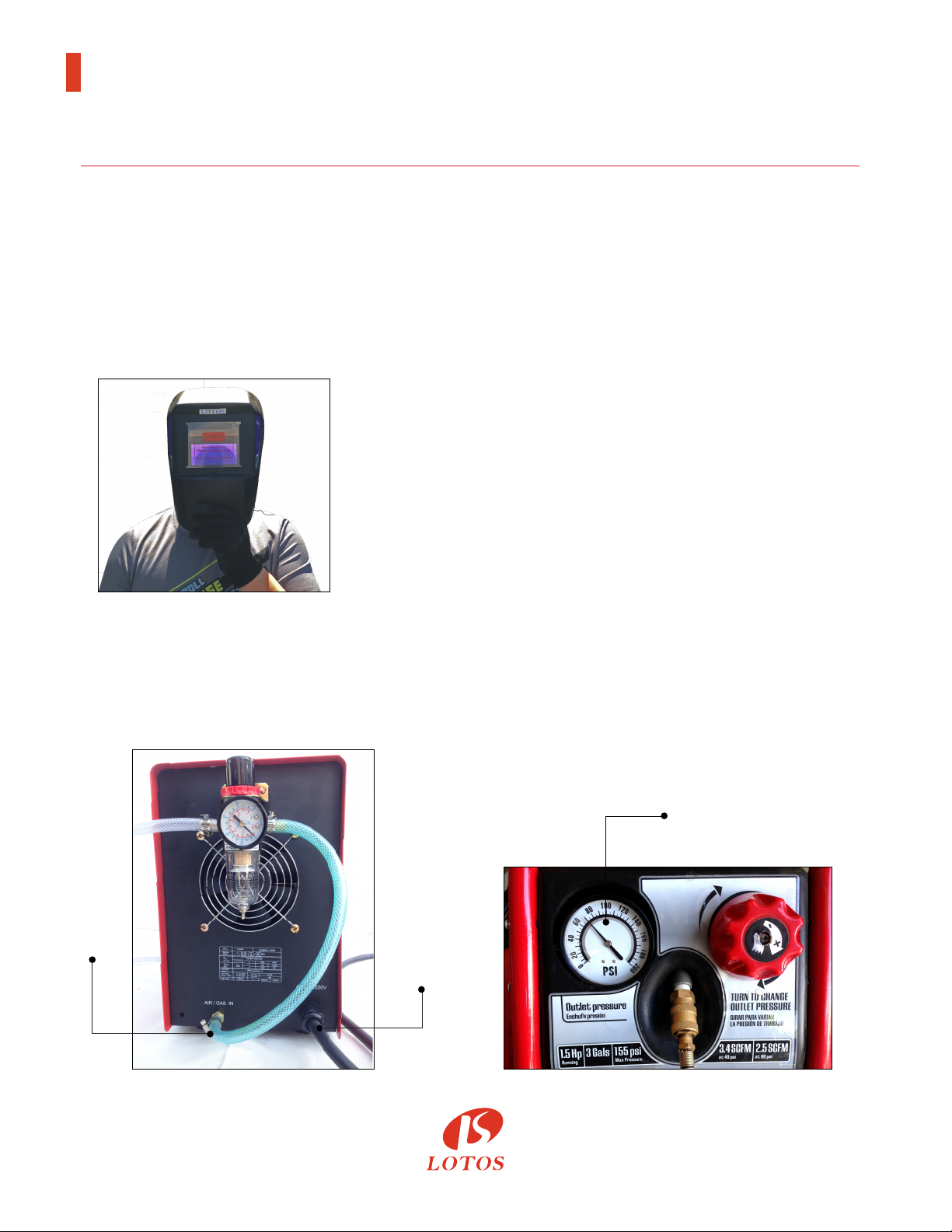
1. Wear a Lotos auto darkening plasma cung helmet
(Figure 1.1, not included in the box. To purchase, please
go to our website.) to protect your eyes from harmful
plasma cung arc radiaon and safety gloves to protect
your hands during welding.
Figure 1.1
2. Connect the machine gas inlet (on the back of the machine, Figure 1.2) with an air compressor
(Figure 1.3) and set the air pressure to 65-70 PSI. (The Air Regulator is oponal if your air
compressor has the capability to control output air pressure.)
65 - 70 PSI
Gas
Inlet
Power
Cord
Figure 1.2 Figure 1.3
®
1
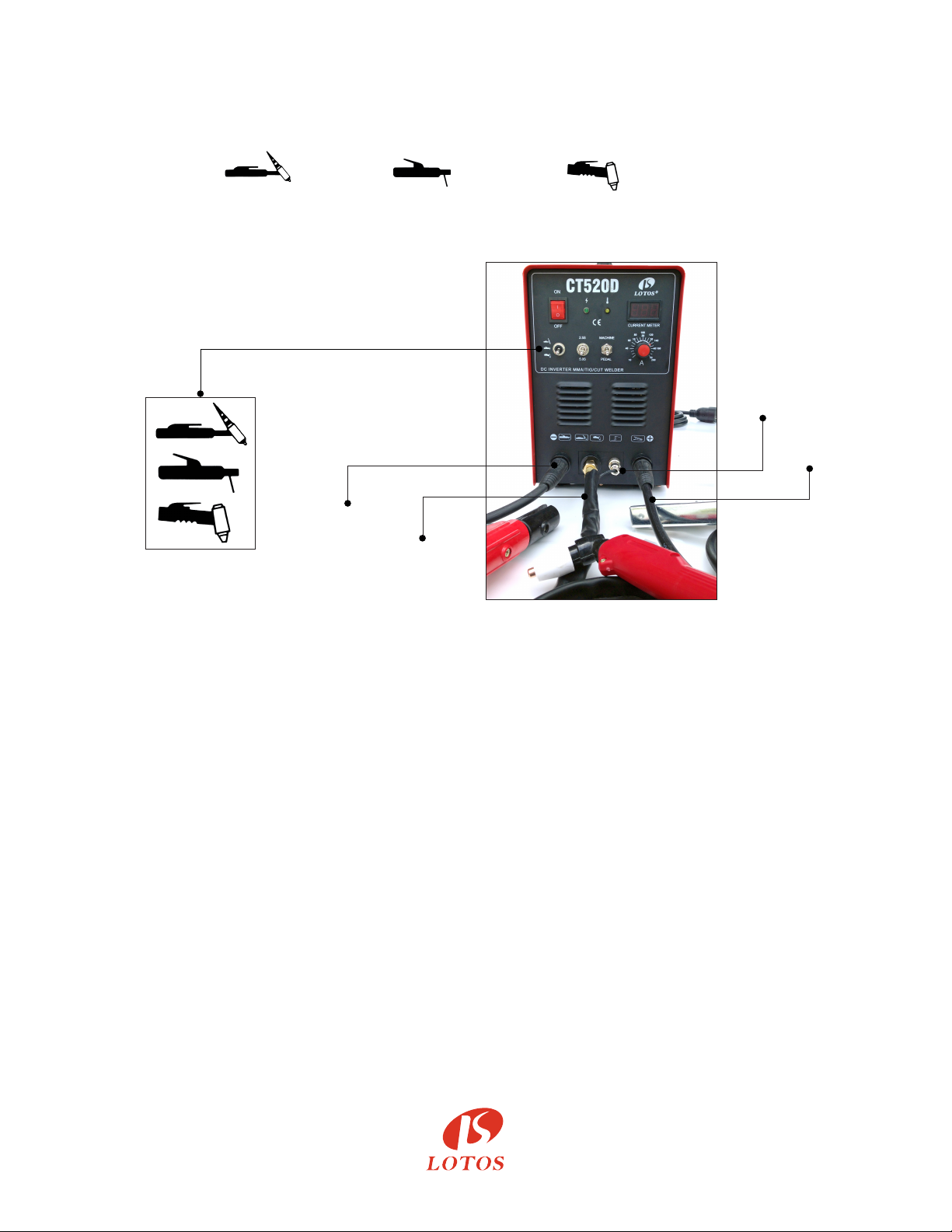
3. Connect your plasma cung torch and ground cable to the front panel of the machine. Make
sure the ground cable is connected on the right hand side where the “+” sign is located.
(Figure 1.4)
- Set TIG Weld /Sck Weld /Plasma Cut switch to Plasma Cut mode.
- Set “2.5S/5S” to “2.5S” Mode.
- Set “Machine/PEDAL” to “Machine” Mode.
- Adjust Current Dial between 10 and 50 amps.
5-pin
Switch
Plug
Ground
Cable
STICK
Welding
Clamp
Plasma
Torch
Output
Figure 1.4
4. Aach the ground clamp to the metal you want to cut. Grind the metal to make sure the clamp
is securely aached to the work piece. Press the trigger of the torch and make sure the air is
owing. Finally, move the torch head to the work piece and start cung.
5. Change your consumables (p, electrode, ring, and cup) if they are worn out. The consumables’
type is LCON. If you want to cut the perfect circle or perfect straight line, order a Lotos
LCK roller guider compass kits from our website www.uwelding.com.
For TIG Welding:
1. Wear our auto darkening helmet and gloves to protect your eyes and hands from any harmful
welding arc. (Please see step 1 in Plasma Cung.)
2. Connect the machine gas inlet (on the back of the machine, Figure 1.5) to the argon regulator
and adjust the knob to set gas pressure between 15 and 20 min/L (an argon regulator is
necessary, Figure 1.6.)
®
2
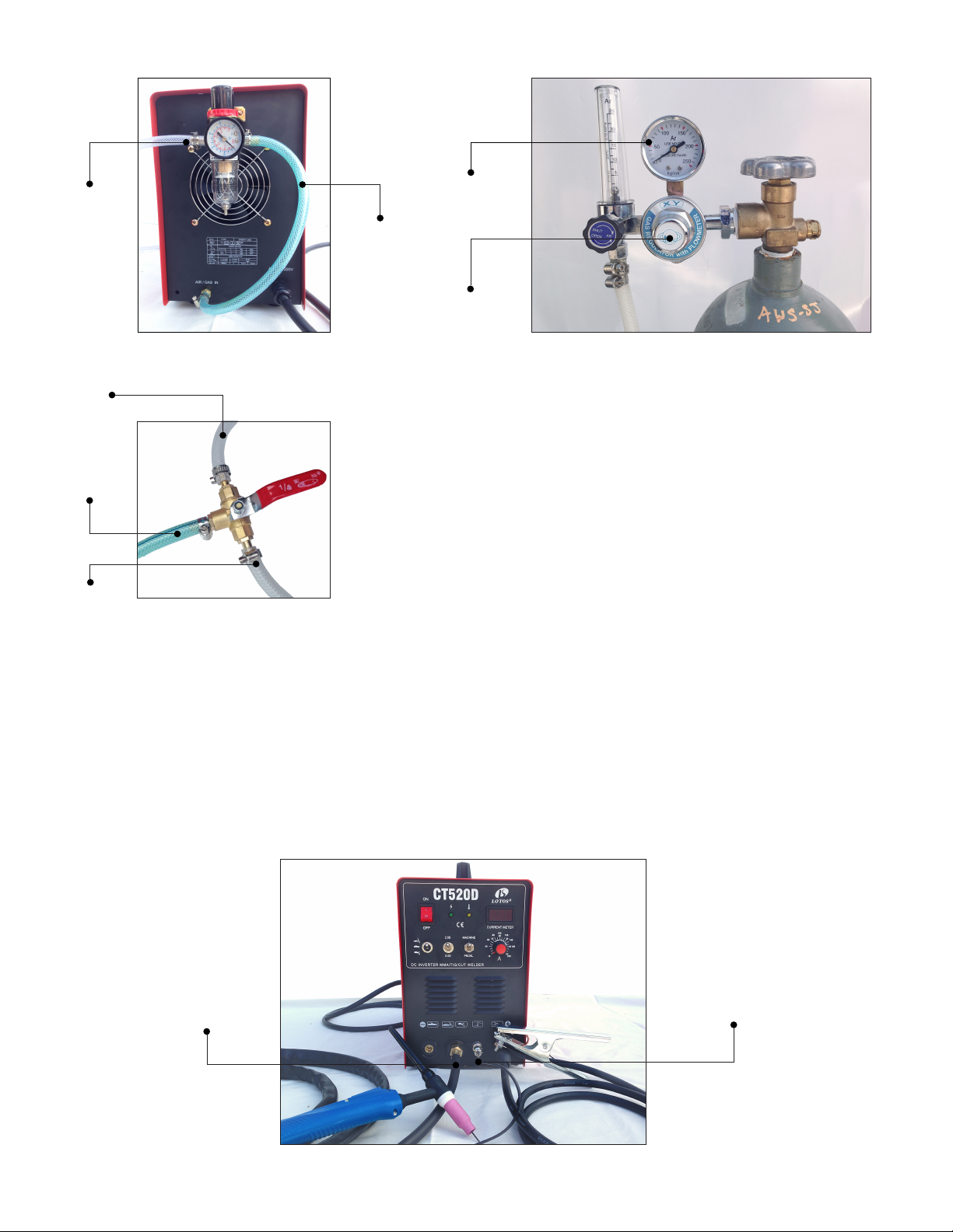
Output
from
Air
Compressor
Argon
Gas
Machine
Air
Compressor
15-20
min/L
Gas
Inlet
Argon
Regulator
Figure 1.5 Figure 1.6
a) If you switch from plasma cung to TIG welding quite oen,
consider buying a LOTOS 3 way valve kit to connect both the
argon tank (Figure 1.7) and the air compressor simultaneously.
Figure 1.7
- Connect your TIG torch and ground cable to the front panel of the machine.
- Make sure the ground cable is connected on the right hand side where the “+” sign is located.
- Set TIG Weld/Sck Weld/Plasma Cut switch to TIG Weld mode (refer to Figure 1.4, page 2).
- Set “2.5S/5S” to “2.5S” mode.
- Set “Machine/PEDAL” to “Machine” mode.
- Adjust current dial from 10 to 200 amps (Figure 1.8).
TIG
Torch
Output
5-pin
Switch
Plug
Figure 1.8
3
b) If you want to dynamically control the welding heat, please use a foot pedal (not included in the
box. To purchase, please go to our website). Then connect the “on/o” connector to your foot
pedal and leave the wire of the TIG torch unplugged.
- Set TIG Weld/Sck Weld/Plasma Cut switch to TIG Weld mode (refer to Figure 1.4, page 2).
- Set “2.5S/5S” to “2.5S” mode.
- Set “Machine/PEDAL” to “Pedal” mode.
- Adjust current dial between 10 and 200 Amp (Figure 1.9).
Foot
Pedal
with
Amp Adjusts
TIG Torch
Output
Unplugged
Ground
Figure 1.9
5-pin
Foot Pedal
Plug
Cable
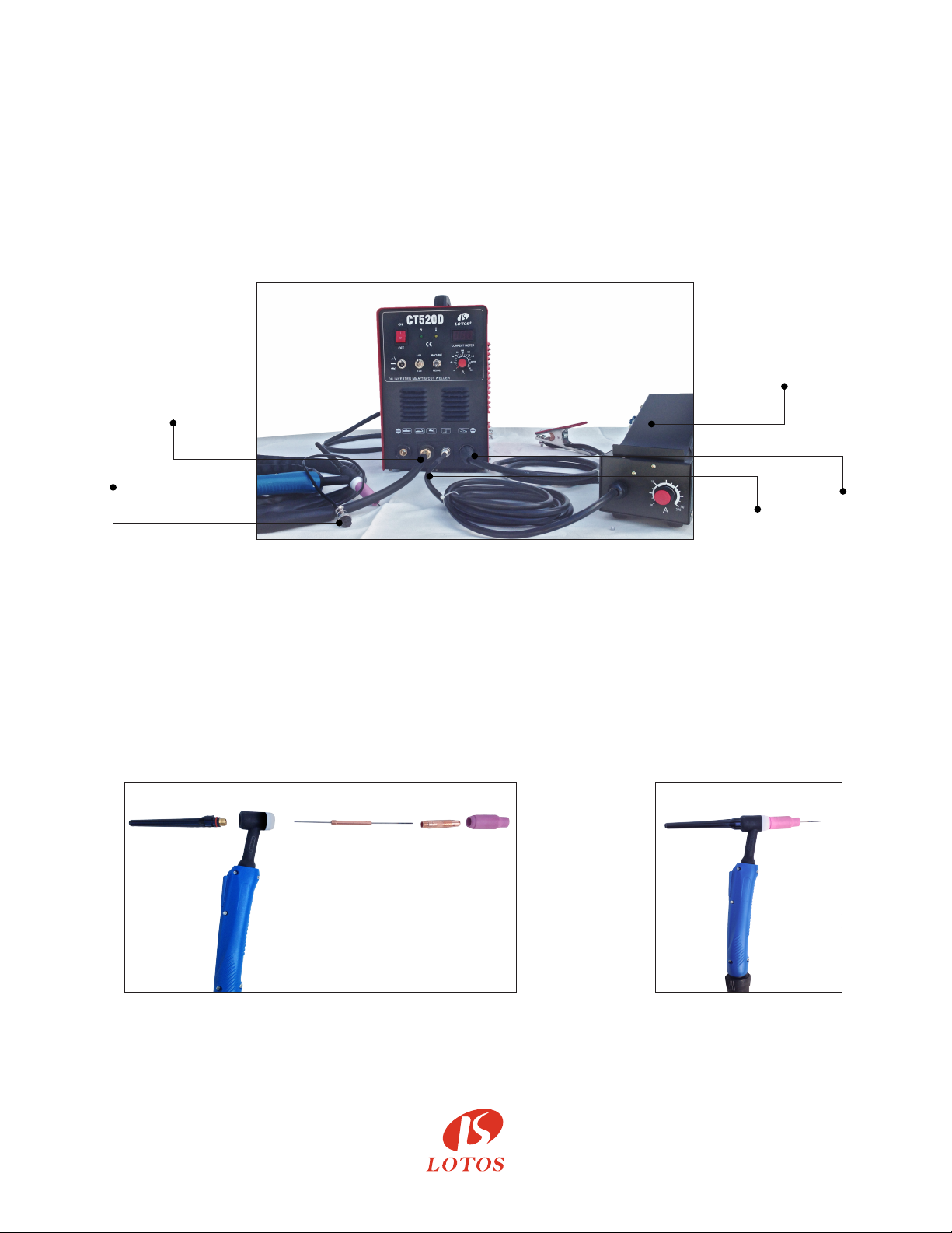
3. TIG torch head parts (Figure 1.10) and assembly (Figure 1.11)
(The tungsten is not included in the picture; please buy proper DC Lotos tungsten electrodes.)
Grind and sharpen the tungsten before rst use.
Figure 1.10 Figure 1.11
®
4
For Sck/Arc/MMA Welding:
1. Wear our auto darkening welding helmet and gloves to protect your eyes and hands from any
harmful welding arc. (Please see step 1 in Plasma Cung.)
2. You don’t need to connect the machine to any gas or air supply. It’s a plug and play.
Panel connecon instrucons:
- Set TIG Weld/Sck Weld/Plasma Cut switch to Sck Weld mode (refer to Figure 1.4, page 2).
- Set “2.5S/5S” to “2.5S” mode.
- Set “Machine/PEDAL” to “Machine” mode.
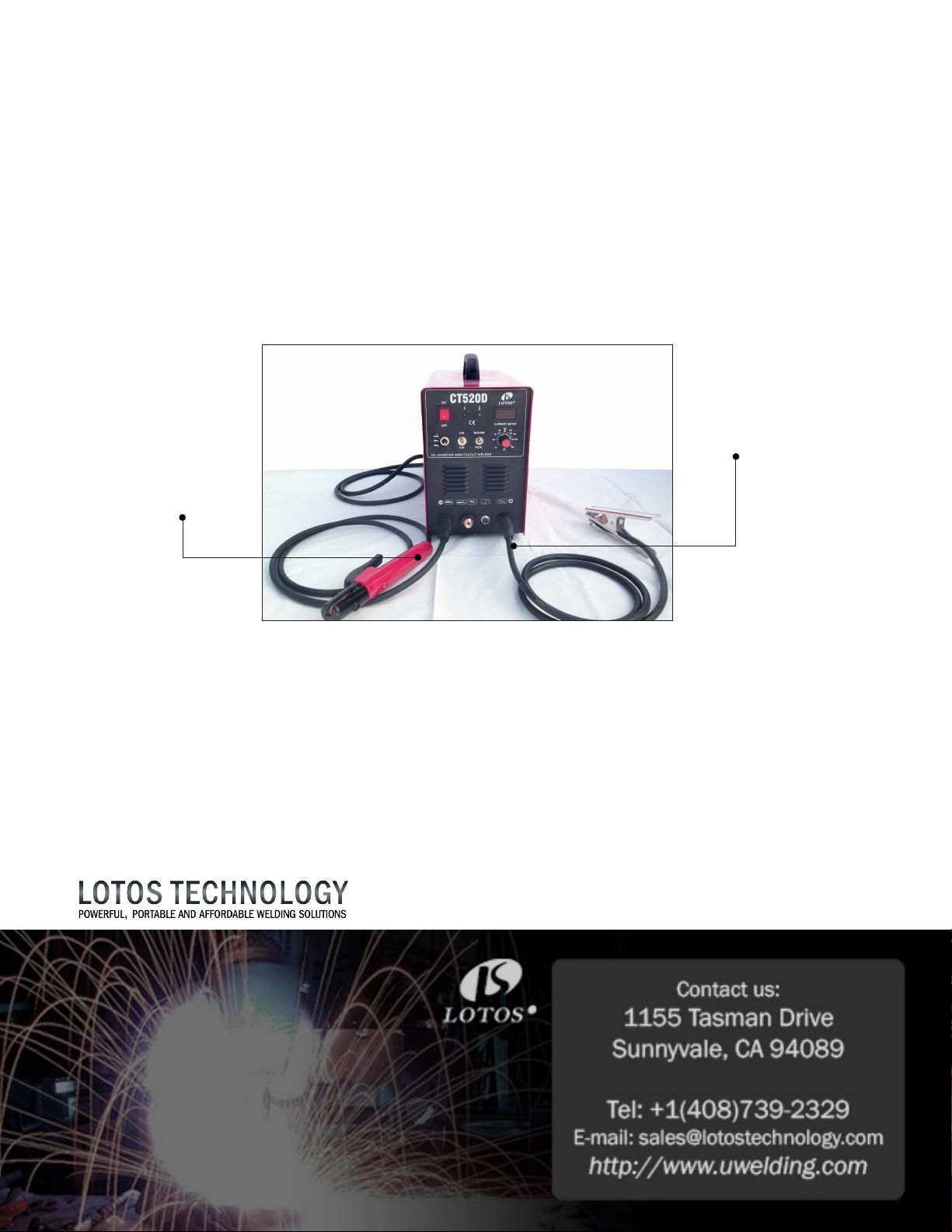
- Adjust current dial between 10 and 200 amps (Figure 1.12).
Ground
Cable
Stick
Welding
Clamp
Figure 1.12
IMPORTANT: To avoid damaging the machine, please be sure to turn o the machine when you
switch from one funcon to another.
All accessories and consumables can be purchased at www.uwelding.com or Lotos’s authorized
resellers.
Thank you for your business!
®

LOTOS CT520D
User Manual
Version: 3.0, June 2017
copyright @ Lotos Technology
www.uwelding.com is operated by Lotos Technology
®

Table of Contents
Introducon 6
Overview ................................................................................
Audience ................................................................................
Safety Precauons
Overview .................................................................................
Cauon Recommendaons .................................................................
Avoiding Fatal Electric Shock ................................................................
Avoiding Harmful Smoke, Gases, and Vapors ..................................................
Avoiding Harmful Arc Emissions/Rays ........................................................
Avoiding Harmful Noises ...................................................................
Fire or Explosion ..........................................................................
Burn Protecon ...........................................................................
Protecng Eyes from Flying Metal or Dirt .....................................................
Pacemakers ..............................................................................
Cylinder Handling .........................................................................
Equipment
General Overview .........................................................................
Main Characteriscs .......................................................................
Specicaons .............................................................................
Adjustor Diagram .........................................................................
Air Regulator Conguraon ................................................................
Connecng Cables to Machine..............................................................
Installaons ..............................................................................
Gas Regulator Installation ..................................................................
Argon Installaon .........................................................................
Tips for Cutting . . . . . . . . . . . . . . . . . . . . . . . . . . . . . . . . . . . . . . . . . . . . . . . . . . . . . . . . . . . . . . . . . . . . . . .
Operaon ...............................................................................
9
7
9
9
9
12
12
13
15
16
16
17
18
6
6
7
7
7
7
7
7
8
8
8
8
8
Instrucon Notes
Working Environment .....................................................................
Safety ...................................................................................
Maintenance .............................................................................
Troubleshoong ..........................................................................
20
For more information and more of our products,
please visit our website at
http://www.uwelding.com/
20
20
21
21
 Loading...