

LorTonE
TS8-C Stainless Steel Item #051-392
TS8 Stainless Steel (Basic) Item #051-391
TS8-C Classic Item #051-092
TS8 Classic (Basic) Item #051-091
TS8-C
InSTruCTIonS and ParTS LIST
(including TS8 Basic)
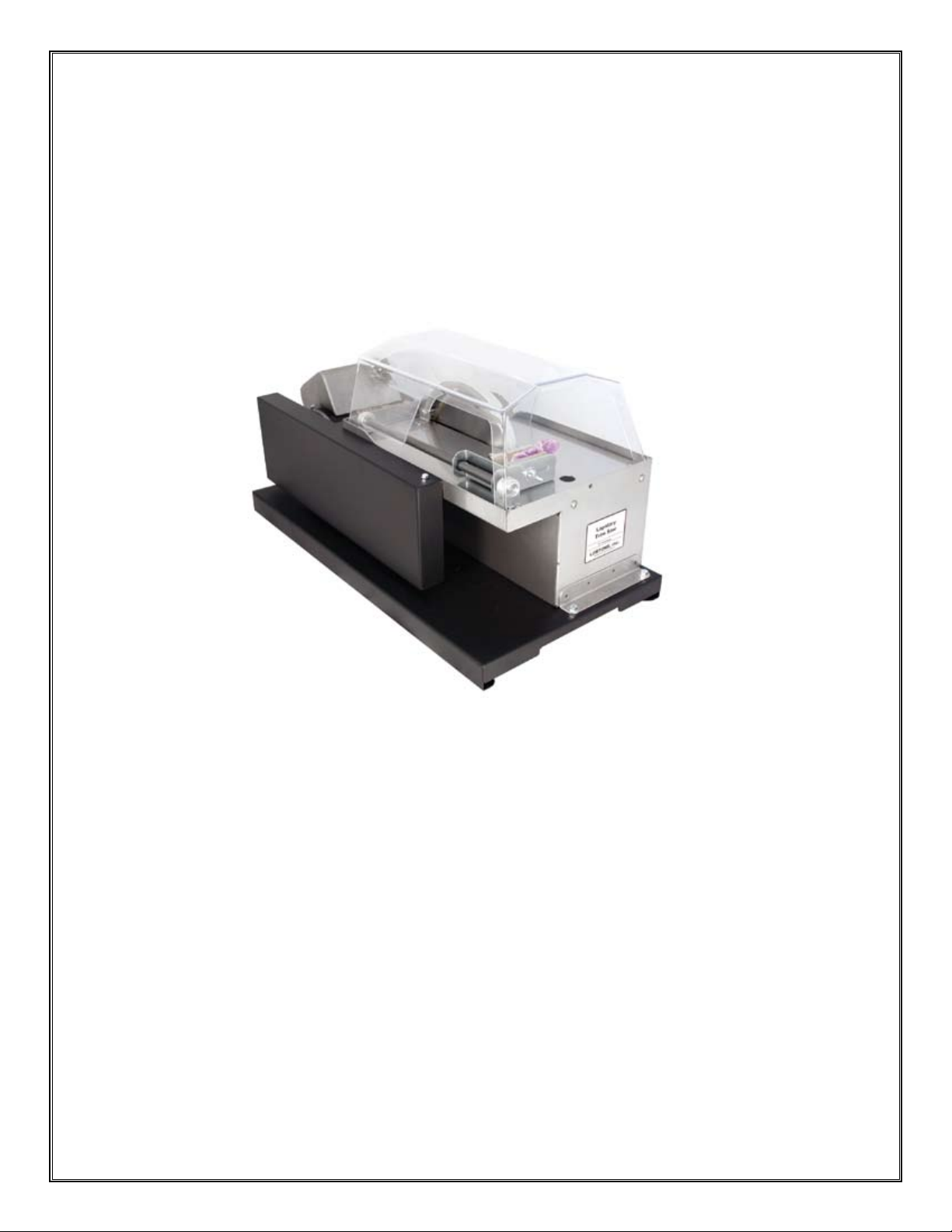
LorTonE Trim Saws are high quality saws for trimming slabs to nished conguration.
Cuts cleanly and easily with excellent visibility and has plenty of room for larger slabs.
For use with oil or water coolants. Follow these basic operating and care instructions to
help keep your saw in optimal running condition.
• Rugged Steel Frame
• Spacious Work Table
• Accepts 8” Blade (included with TS8-C)
• Optional Clear Hood (included with TS8-C)
• Optional Vise (included with TS8-C)
TS8-C Stainless Steel Trim Saw (shown)
8/12
LORTONE, inc • 12130 Cyrus Way, Mukilteo, WA 98275 • Phone: 425-493-1600
Copyright © 2009 Lortone, Inc
Page 1
SETTING UP YOUR MACHINE
Check to make sure you have the following parts:
•
(1) TS8 Frame with Bearings and Drive Belt (1) Blade Guard
(1) Splash Shield (1) Blade (included in TS8-C only)
(1) Belt Guard (1) Vise (included in TS8-C only)
(1) Belt (included in TS8-C only) (1) Hood (included in TS8-C only)
(1) Operators Manual (1) Warranty Card
If any parts are missing, please contact your dealers or the factory immediately.
Read the following instructions before assembly or use of your machine. Failure to
follow instructions could result in damage to the machine or injury to operator.
IMPORTANT!!!
MOTOR INSTALLATION
Note: A 1/3 hp, 1725 RPM is recommended for proper operation. Motor pulley should be 2” to 2 1/2” diameter.
Drive belt should be selected to match desired motor mounting position. Pulley and drive belt are included with
the TS8-C only.
Make sure the saw is secured to the base (TS8-C). For TS8 Basic, secure saw and motor to work area.
•
Place motor pulley on the motor shaft and securely tighten the set screw on at of motor shaft.
•
Install belt and adjust motor to obtain correct belt tension. Do not overtighten the belt as this will lead to
•
excessive noise and premature bearing wear. The belt should not deect more than 1”.
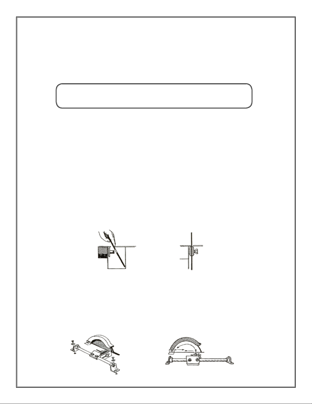
BLADE INSTALLATION
Slip the blade into the saw slot at an angle (Fig. 1) and slide it onto the shaft.
•
Slide the second ange next to the blade and tighten the arbor nut securely (Fig. 2).
•
Do not over tighten as this can warp the blade.
•
Fig. 1
Fig. 2
OPTIONAL VISE INSTALLATION
Attach the vise parallel to the trim table using the two self-tapping screws (Fig. 3).
•
Clamp a pencil into the vise with the point just touching the front of the blade behind the rim.
•
Rotate the blade (Fig. 4) rearward so pencil mark shows above the table.
•
Slide the vise and pencil rearward. Pencil point should touch the blade at the same spot.
•
If necessary loosen the screws and adjust the guide bar supports.
•
Fig. 4
8/12
Fig. 3
LORTONE, inc • 12130 Cyrus Way, Mukilteo, WA 98275 • Phone: 425-493-1600
Copyright © 2009 Lortone, Inc
Page 2
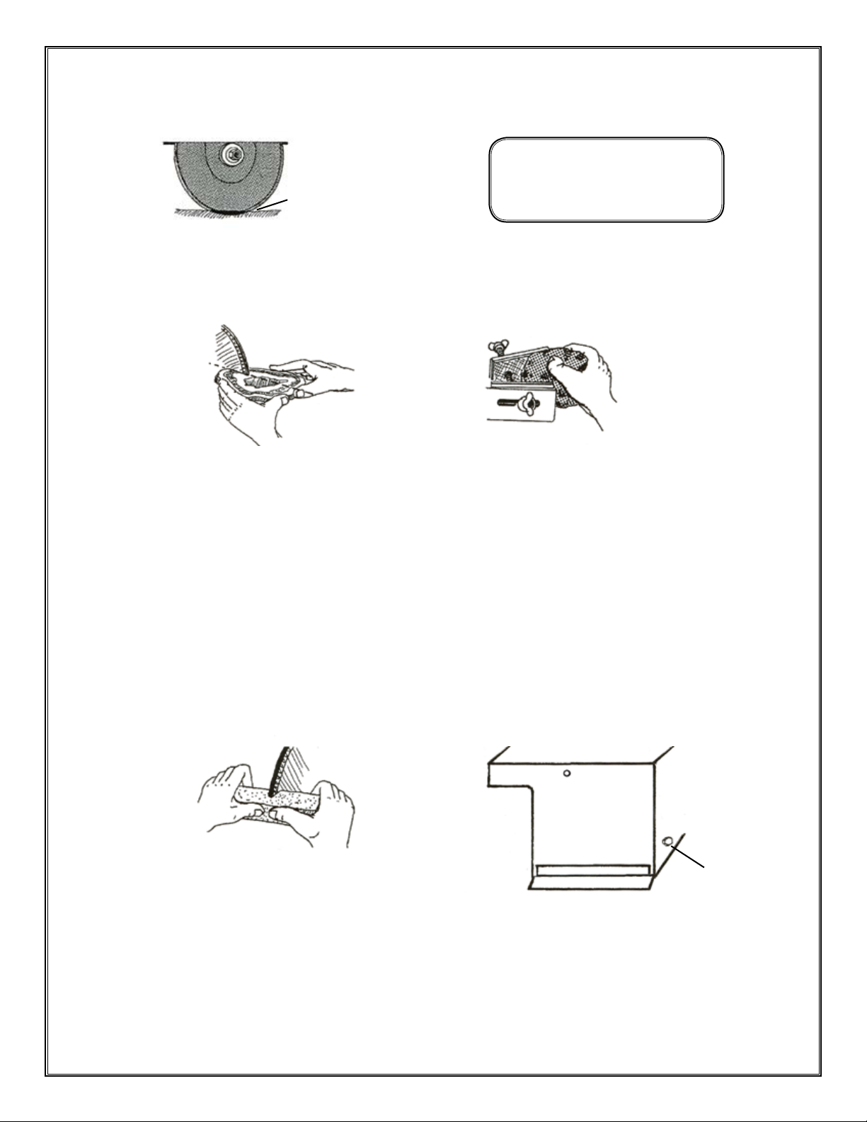
OPERATION
•
Fill the coolant tank with lapidary cutting oil until coolant covers approximately 1/4” of the blade rim (Fig. 5).
CAUTION!!!
Do not operate without coolant.
1/4”
Fig. 5
Cut slowly using a straight forward motion (Fig. 6). Do not force stone into blade or apply side pressure.
•
If using the vise, make sure the rock is clamped rmly before starting (Fig. 7). Slowly feed stone into blade.
•
Injury to operator or damage to
blade and machine may occur.
Fig. 7
Fig. 6
MAINTENANCE
The TS-8 is designed for minimum maintenance however the following should be periodically checked.
Check belt for wear and proper tension. Refer to Motor Installation.
•
Check blade for wear and correct alignment.
•
Keep blade sharpened by periodically making a cut into a dressing stick or an old medium grit
•
aluminum oxide or silicon carbide grinding wheel. This helps to expose fresh diamond crystals. (Fig 8).
Cascade™ dressing sticks #566-012 are recommended.
•
Maintain a proper coolant level.
Change the coolant frequently or when it becomes dirty (Fig. 9).
•
Fig. 9
8/12
Fig. 8
LORTONE, inc • 12130 Cyrus Way, Mukilteo, WA 98275 • Phone: 425-493-1600
Copyright © 2009 Lortone, Inc
Remove plug to
drain coolant.
Page 3

PARTS LIST TS8 & TS8-C
Part No. Description
A 053-108 Arbor Shaft with Flange
B 057-002 Splash Shield
C 056-006 Blade Guard
D 051-100 Tank Assembly (Classic)
D 051-300 Tank Assembly (Stainless Steel)
E 051-101 Trim Table Assembly
F 053-028 Machined Flange, 2” x 5/8”
G 200-006 Bearing (2 required)
H 204-001 Bearing Strap (2 required)
I 205-010 Felt Washer
J 211-015 Arbor Pulley, 2 1/2” x 3/4”
K 216-001 Drain Plug
L 481-057 Hex Nut
M 051-102 TS8 Belt Guard
Included with TS8-C Only
N 074-091 Hood
O 071-093 Vise
N
(Not shown)
211-013 2 1/2” x 1/2” Motor pulley
210-035 4L-310 Belt
300-022 1/3 hp motor
522-047 8” Blade
J
M
C
O
B
E
A
F
L
I
D
G
H
K
8/12
LORTONE, inc • 12130 Cyrus Way, Mukilteo, WA 98275 • Phone: 425-493-1600
Copyright © 2009 Lortone, Inc
Page 4
 Loading...