

LORTONE
Instructions and Parts List
Classic 6-2 #035-290
Classic 6-4 #036-290
Classic 6-6 #039-290
Classic 8-2 #037-290
Classic 8-4 #038-290
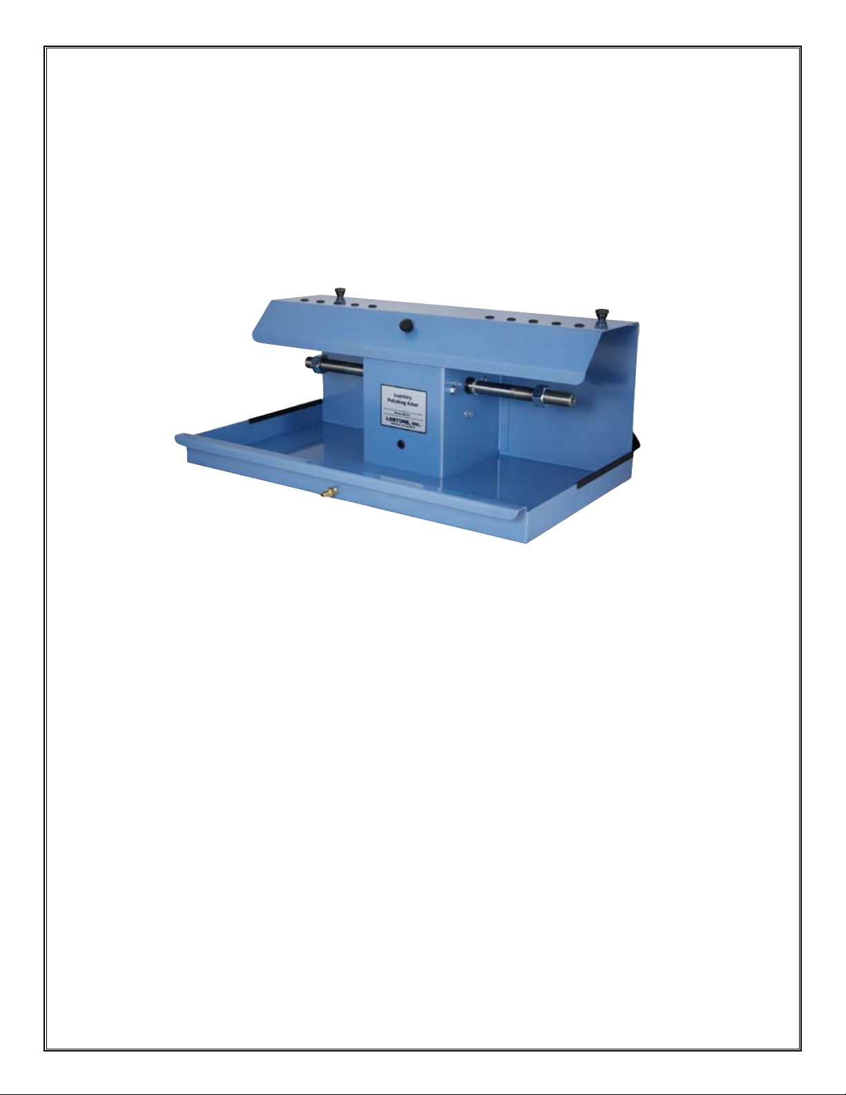
Classic Series 6” & 8”
Grinding & Polishing Arbors
Ideal for lapidary and glass work, Lortone Arbors are used for grinding and polishing.
Their widely spaced wheel centers are easy to use and can accommodate a variety of
grinding/polishing wheels and drums. We use a sturdy welded steel frame coated with
a high quality powder-coat nish for durability and smooth running rubber mounted
bearings for quiet operation. Tapped shaft ends make installing spin-on polish heads
simple. Requires the use of an overhead drip or pump fed coolant system. Motor and
wheels not included.
• Comfortable, widely spaced wheel centers
• Clean, Quiet and efcient
• Sturdy welded steel frame
• Replaceable rubber mounted bearings for quite operation.
01/13
LORTONE, inc • 12130 Cyrus Way, Mukilteo, WA 98275 U.S.A
Phone: 425-493-1600 • www.lortone.com
Copyright © 2010 Lortone, Inc
Page 1
SETTING UP YOUR MACHINE
•
Check the parts list to make sure all parts are included. If any parts are missing, please contact your
dealer or the factory immediately.
Note: Unit does not come with a drive motor. It may be purchased separately.
•
Place unit on a clean, sturdy work table. Secure the unit to the work surface using the included hold-down
clips. If not using the hold-down clips, place a non-slip rubber mat under the unit.
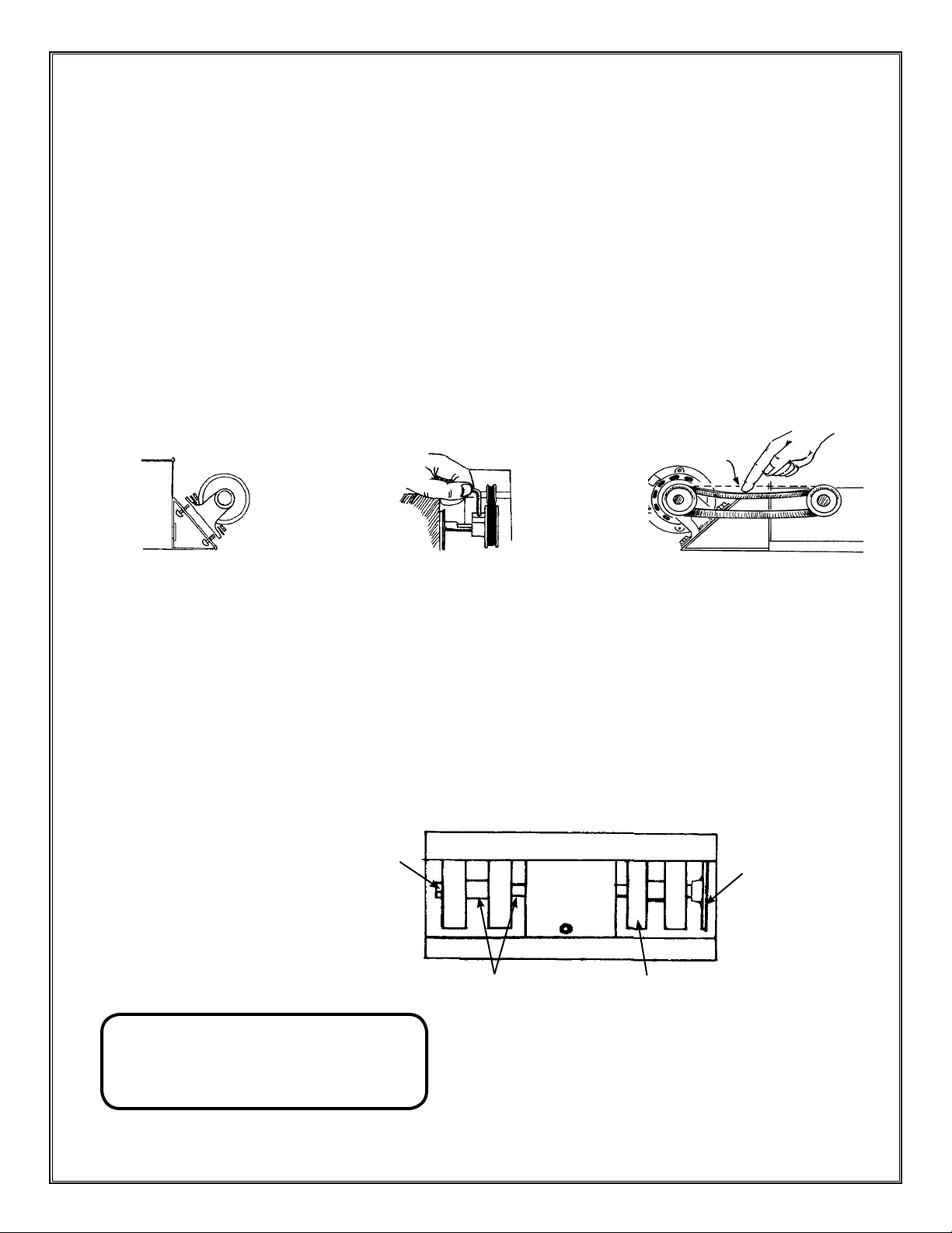
MOTOR INSTALLATION
•
Secure motor to motor mount with bolts provided.
•
Place motor pulley on the motor shaft and tighten set screw securely.
•
Install belt and adjust motor for correct belt alignment and tension. Do not overtighten the belt as this will
lead to excessive noise and premature bearing wear.
Secure motor to mount with bolts.
WHEEL & BELT INSTALLATION
•
Carefully install belts on drums. Slightly compress the drums if required.
•
Install the drums & wheels on the shaft using the anges and spacer provided. Flanges must be installed
with the concave side toward the grinding wheel or expandable drum. Note the proper direction of rotation.
•
Install spacers between wheels as needed and tighten the threaded nuts securely.
•
Polish heads may be installed on either side depending upon your preference.
Slide pulley onto shaft
and tighten securely.
Slide pulley onto shaft and tighten securely.
Using spacers
as needed.
Grinding wheel or
expandable drum
Adjust belt tension to about 3/4”.
Optional Polish Head
01/13
CAUTION!
Do not run drums without belts in place.
Failure to follow instructions can result in
damage to the machine or serious injury.
LORTONE, inc • 12130 Cyrus Way, Mukilteo, WA 98275 U.S.A
Phone: 425-493-1600 • www.lortone.com
Page 2
Copyright © 2010 Lortone, Inc

OPERATION
•
Do Not Operate Without Water! Using this machine without water can generate signicant amounts of
dust and result in reduced life of sanding belts and wheels.
•
A gravity feed water system (Fig. 1) or an under wheel water spitter with pump (Fig. 2) should be used to
supply water to the wheels during operation.
•
Always wear eye protection and dust mask when using equipment. Failure to do so can result in severe
injury or illness.
•
Turn on motor and run arbor up to speed prior to applying water to wheels.
•
After use, turn water source off and run wheels and drums for several seconds to remove excess water.
•
Drain unit and wipe dry after use. If desired, a drain system can be attached for continuous draining
during use (Fig. 3). If water will be left in machine, add a small amount of rust inhibitor.
Fig. 1
Optional:
Overhead Water System
Item # 075-097
CAUTION
Do not operate without water.
Injury to operator or damage to
belts and wheels may occur.
Fig. 2
Optional:
Underwheel Water Fountain
Item # 075-096
If using a spitter head, ll unit with 1/2” of water
and position spitter head below wheel in use.
01/13
Fig. 3
Typical Drain System
LORTONE, inc • 12130 Cyrus Way, Mukilteo, WA 98275 U.S.A
Phone: 425-493-1600 • www.lortone.com
Copyright © 2010 Lortone, Inc
Page 3

Classic Arbor
T
U
B
D
01/13
T
F
G
Q
V
A
O
P
E
H
S
Classic 6-6
N
R
Arbor Shaft
(shown)
Part No. Description 6-2 6-4 6-6 8-2 8-4
A Frame 035-200 036-200 039-200 037-200 038-200
B Removable Hood 035-201 036-201 039-201 037-201 038-201
C Arbor Shaft 037-001 036-001 039-003 037-001 036-001
D Belt Guard 039-205 039-205 039-205 038-205 038-205
E 033-025 Hold Down Clip 2 2 2 2 2
F Drive Belt 210-030 210-030 210-030 210-031 210-031
G 211-013 Motor Pulley, 2 1/2” x 1/2” 1 1 1 1 1
211-015 Arbor Pulley, 2 1/2” x 3/4” 1 1 1 1 1
H
200-006 Arbor Bearing 2 2 2 2 2
I
206-023 Retaining Ring 2 2 2 2 2
J
Bearing Hat (2) 063-008 063-008 063-008 063-008 063-008
K
L 240-069 Rubber Bearing Isolator 2 2 2 2 2
M 481-026 Hex Nut, 3/4-16 RH 1 1 1 1 1
N 481-046 Hex Nut, 3/4-16 LH 1 1 1 1 1
217-020 Insulating Bushing 2 2 2 2 2
O
216-052 1/8” MPT Tube Connector 1 1 1 1 1
P
Q 300-022 1/3 HP Motor (optional) - - - - -
R 101-013 Plated Flange, 2” x 3/4” 4 8 12 - -
R 101-023 Plated Flange, 3” x 3/4” - - - 4 8
S 105-002 1/4” Aluminum Spacer 2 2 - 2 2
S 105-006 3/4” Aluminum Spacer 2 2 - 2 2
S 105-008 1” Aluminum Spacer 2 2 - 2 2
R 105-010 1-1/2” Aluminum Spacer - 2 - - 2
S 105-013 2” Aluminum Spacer - 2 4 - 2
T 290-015 Thumb Screw 3 3 3 3 3
U 320-006 Grommets 4 10 10 6 10
C
J
LORTONE, inc • 12130 Cyrus Way, Mukilteo, WA 98275 U.S.A
Phone: 425-493-1600 • www.lortone.com
I
L
K
Model
M
Page 4
Copyright © 2010 Lortone, Inc
 Loading...