

Page 1
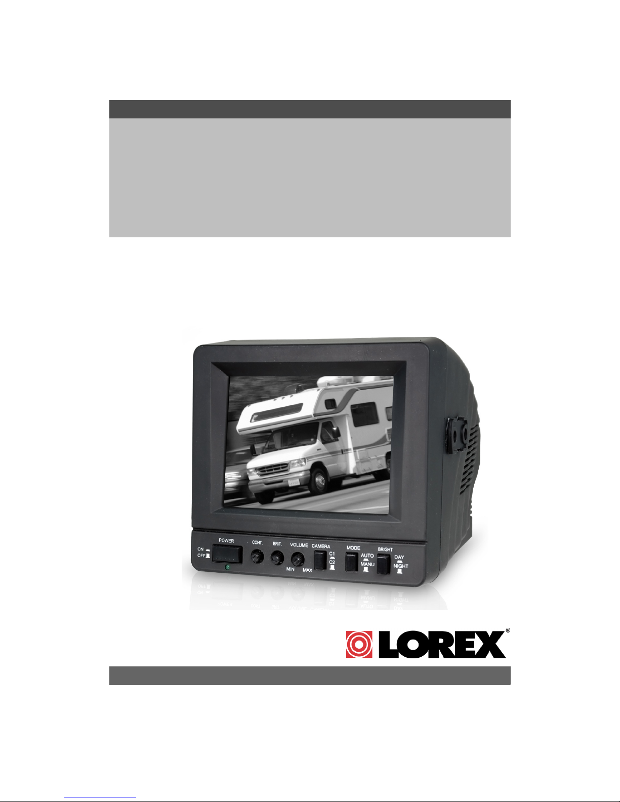
5” B&W Rear View
Safety System Monitor
Instruction Manual
English Version 1.0
MODEL:
MO453
Copyright © 2007 LOREX Technology Inc.
www.lorexcctv.com
Page 2
Thank you for purchasing the Lorex 5” Black & White Rear View Safety Monitor. This
monitor (when installed with MO453 Cameras) helps to prevent backing-up and
parking accidents by allowing you to view or check on the traffic behind your vehicle,
or when rounding corners (blind spot prevention).
This system is suitable for waste trucks, RV campers, vans, delivery vehicles &
cars.To learn more about this system or to find out more about our products available,
please visit our website at:
http://www.lorexcctv.com
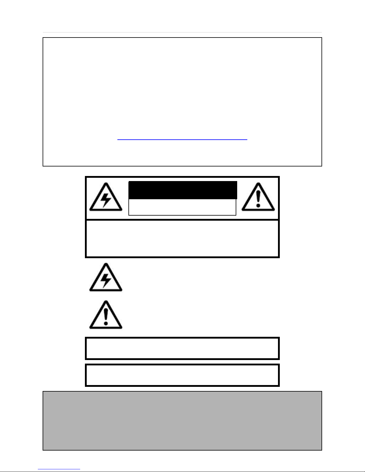
CAUTION
RISK OF ELECTRIC SHOCK
DO NOT OPEN
CAUTION: TO REDUCE THE RISK OF ELECTRIC SHOCK
DO NOT REMOVE COVER (OR BACK).
NO USER SERVICEABLE PARTS INSIDE.
REFER SERVICING TO A QUALIFIED SERVICE PERSONNEL
The lightning flash with arrowhead symbol, within an
equilateral triangle, is intended to alert the user to the
presence of uninsulated “dangerous voltage” within the
product’s enclosure that may be of sufficient magnitude
to constitute a risk of electric shock to persons.
The exclamation point within an equilateral triangle is
intended to alert the user to the presence of important
operating and maintenance (servicing) instructions in
the literature accompanying the appliance.
WARNING: TO PREVENT FIRE OR SHOCK HAZARD,
DO NOT EXPOSE THIS UNIT TO RAIN OR MOISTURE.
CAUTION: TO PREVENT ELECTRIC SHOCK, MATCH WIDE BLADE
OF PLUG TO WIDE SLOT, FULLY INSERT.
Warning: This Rear Observation System is to be used with, not instead of, other
viewing aids in your vehicle such as front, rear, and side mirrors. Safe driving
practices, alertness, and visual and physical fitness are prerequisites for your driving
safety. The Manufacturer shall not be held liable for any accidents which may occur
2
while operating this system.
Page 3

General Precautions
NOTE
This equipment has been certified and found to comply with the limits regulated by FCC, EMC, and LVD. Therefore, it
is designated to provide reasonable protection against interference and will not cause interference with other appliance
usage.
However, it is imperative that the user follows this manuals guidelines to avoid improper usage which may result in
damage to the unit, electrical shock and fire hazard injury
In order to improve the feature functions and quality of this product, the specifications are subject to change without
notice from time to time.
FCC CLASS B NOTICE
Note:
This equipment has been tested and found to comply with the limits for a Class B digital device, pursuant to Part
15 of the FCC Rules. These limits are designed to provide reasonable protection against harmful interference in
a residential installation. This equipment generates, uses, and can radiate radio frequency energy and, if not installed and used in accordance with the instruction, may cause harmful interference to radio communications.
However, there is no guarantee that interference will not occur in a particular installation. If this equipment does
cause harmful interference to radio or television reception (which can be determined by turning the equipment on
and off), the user is encouraged to try to correct the interference by one or more of the following measures:
z Reorient or relocate the receiving antenna
z Increase the separation between the equipment and receiver
z Connect the equipment into an outlet on a circuit different from that to which the receiver is
connected
z Consult the dealer or an experienced radio or television technician for assistance
General Precautions
1. All warnings and instructions of this manual should be followed
2. Remove the plug from the outlet before cleaning. Do not use liquid aerosol detergents. Use a water dampened cloth
for cleaning
3. Do not use this unit in humid or wet places
4. Keep enough space around the unit for ventilation. Slots and openings in the storage cabinet should not be blocked
5. During lightning storms, or when the unit is not used for a long time, disconnect the power supply, antenna, and cables
to protect the unit from electrical surge
LOREX TECHNOLOGY INC.
http://www.lorexcctv.com
3
Page 4

Table of Contents
Table of Contents
Getting Started .......................................................................................... 5
Operating Instructions ............................................................................... 5
MO453 - Front ........................................................................................... 6
MO453 - Back ........................................................................................... 7
Monitor Overview ...................................................................................... 8
Monitor Installation .................................................................................... 8
Connecting the Monitor Power .................................................................. 9
Full Connection Diagram .......................................................................... 9
System Specifications - Appendix #1 ...................................................... 10
Lorex CVA453 Accessory Cables - Appendix #2..................................... 11
MO453 FEATURES
• Automatic activation of camera when gear is shifted into reverse.
• Built-in 2 Camera input.
• Built-in microphone on camera (One-way audio).
• Built-in Brightness, Contrast and Volume Control.
• Selector switch for Normal and Reverse image viewing.
• Waterproof B&W CCD image sensor camera in a compact die-cast housing.
• Input voltage 12-32 Volt DC.
• Monitor equipped with day/night selector switch for brightness compensation.
• Wide Field of View: 94°Horizontal 72°Vertical 110°Diagonal.
• 2 piece Waterproof Camera connecting cable (prevents corrosion) with 4 pin connector.
• Camera selector switch.
4
Page 5

Getting Started
The MO453 Rearview System comes with the following components:
Getting Started
5” B&W CRT Monitor
CHECK YOUR PACKAGE TO CONFIRM THAT YOU HAVE RECEIVED THE COMPLETE
SYSTEM, INCLUDING ALL COMPONENTS SHOWN ABOVE.
Mounting Hardware and Brackets
for Monitor and Camera
Sunshade for MonitorPower cable and Harness
Operating Instructions
• When you turn the ignition key to the ON position, power is supplied to the monitor. The
monitor will automatically be in standby mode, even if the Power button is not pushed in.
• When you push the power button you can manually view the picture from the camera(s).
• When the power button is not pushed in, and you shift the gear into reverse, the monitor will
automatically display the image from selected Camera (if the Auto/Manual switch is in the
AUTO position).
5
Page 6

RVMO453 - Front
RVMO453 - Front
1
1. POWER SWITCH - Turns the monitor ON/OFF:
• Press the power switch to turn the monitor ON. The green LED indicator will illuminate.
• Press the power switch again to turn the monitor OFF (STANDBY MODE).The green LED
indicator will extinguish.
NOTE: When you shift into reverse gear, the monitor will automatically display the image from
Camera 1, when the system is in Auto mode.
2
3 4 5
6
7
2. CONTRAST CONTROL - Adjusts the contrast control for the optimal picture. Turn the dial
clockwise to increase the picture contrast, and counterclockwise to decrease it.
3. BRIGHTNESS - Adjust the brightness control for the desired optimal picture. Turn the dial
clockwise to increase the picture brightness, and counterclockwise to decrease it.
4. VOLUME CONTROL - Adjusts the volume to the Monitor. Turn the control clockwise to increase
the volume, and counterclockwise to decrease it.
5. CAMERA SWITCHER (C1 / C2) - Press the Camera Switcher button to switch the picture view
from Camera 1 to Camera 2 (second camera is sold separately).
• Press the button in to switch to Camera 1.
• Press the button again to switch to Camera 2.
NOTE: When the vehicle changes into reverse gear, the system will automatically display the
picture from Camera 1, regardless of the Camera Switcher position.
6. MODE CONTROL - Sets the system to Automatic or Manual camera switching. Press the button
in to select Automatic switching mode. Press the button again to select Manual switching mode.
NOTE: When you shift into reverse gear, the monitor will automatically display the image from
Camera 1, when the system is in Auto mode. The selected camera will be displayed regardless
of the power switch position.
7. BRIGHT CONTROL - Automatically optimizes the picture to compensate for daylight or night.
Press the button in to select Night mode. Press the button again to select Daylight mode.
6
Page 7

MO453 - Back
MO453 - Back
1
1. CAMERA 1 / CAMERA 2 INPUTS - Allows 2 Cameras (4-Pin) to connect to the system.
• Connect the provided camera to the first channel (C1).
• An additional camera can be connected to C2 (not included).
• Connect the B&W video camera to the monitor with the supplied cable.
2 3 4 5 6
• The monitor supplies power to the cameras
2. VIDEO OUTPUT - Connects the system video to a second TV or monitor using a Video RCA
cable (not included), or to the Video input of a VCR/DVR for recording.
3. AUDIO OUTPUT - Connects the system audio to a second TV or monitor using an Audio RCA
cable (not included), or to the Audio input of a VCR/DVR for recording.
4. EXTERNAL SPEAKER PORT - Connects the system to external Speakers (not included).
5. MIRROR / NORMAL SWITCH - Changes the view on Camera 1 and Camera 2 to Mirrored or
Normal view.
NOTE: This switch has been set to Mirror (Reversed Image) during production. When viewing
behind the vehicle when reversing, confirm that this switch is set to the MIR position. Make sure
the image appearing on the display is reversed right to left, just as it appears in a rear-view
mirror.
6. POWER CONNECTOR - Insert the supplied power cable connector firmly until it is locked in
place. To remove the power connector, press and hold the clip, and pull out.
7
Page 8

Monitor Overview
Monitor Overview
Monitor Installation
1. Determine the location to mount the monitor. Install the monitor mounting bracket by placing the
screw into the center hole. Rotate and adjust the bracket by turning it left and right for the best
placement. Screw in the slide holes on the bracket and tighten the screws.
2. Mount the monitor onto the bracket by using the supplied screws. Adjust the monitor up and
down to the best position and tighten the screws.
3. If necessary attach the sun shield on top of the monitor.
Connecting the Monitor and Cables
1. Connect the cameras to the camera input sockets marked C1 and C2 on the back of the monitor.
NOTE: Connect the backup (reverse gear) camera into the C1 (camera 1) port.
2. Plug the power harness into the socket marked POWER at the back of the monitor.
8
Page 9

Connecting the Monitor Power
Connecting the Monitor Power
The diagram below outlines the connections for the
power cable:
NOTE: The Red wire with the fuse holder should be
connected to vehicle ACC Terminal; the Brown wire to
reverse gear relay; and the Black wire to the chassis
ground.
Full Connection Diagram
1. Connect the RED wire to the (12V – 32V DC) power terminal, which powers the system when
the ignition key is turned on the vehicle.
2. Connect the BLACK wire to a metal portion of the vehicle or the negative battery post.
3. Connect the BROWN wire to the switched power output terminal of the “R” (reverse) gear.
4. Connect the WHITE wire to the Dimmer line.
9
Page 10

System Specifications - Appendix #1
System Specifications - Appendix #1
Picture Tube
Black and White
7” Picture (measured diagonally)
90° Deflection angle
Picture Image Factory preset to reverse image
Picture Resolution 600 TV Lines
Power Connector Red: Positive 12V~32V Input
Brown: Reverse Gear 12V ~ 32V input
Black: Ground
White: Dimmer
Inputs 4-pin multi connector
1. Video input 1.0 Vp-p, 75ohm
2. Audio
3. 12V, 0.2A DC (output)
4. Ground
Audio Output (S-P) 8 ohm 0.5 watt max.
Audio Output (phone Jack)
Video Output (phone jack) 75 ohm, 1 Vp-p
Power Requirements 12V ~ 32V DC (negative ground)
10K, 150 mV ms
Power Consumption 10.5 W Maximum
Operating Temperature 5°F ~ 140°F
°C ~ 60°C
-15
Storage Temperature -13
Dimensions 6.3” (W) x 5.9” (H) x 8.7” (D)
Weight (aprox.) 3.05 lbs / 1.38 kg
°F ~ 185°F
-25
°C ~ 85°C
160mm (W) x 150mm (H) x 220mm (D)
10
Page 11

Lorex CVA453 Accessory Cables - Appendix #2
Lorex CVA453 Accessory Cables - Appendix #2
Additional adapter cables are available for backward compatibility between the Lorex 452 Series
and the Sentinel CCTV 452 Series Rear view systems.
Adaptor Cable #1 - CA452 (Camera
Extension Cable) to MO453 (Monitor)
Connects the Sentinel CA452 Camera Extension
Cable to the Lorex CA453 Monitor.
Adaptor Cable #2 - CA453 (Camera
Extension Cable) to MO452 (Monitor)
Connects the Lorex CA453 Camera Extension
Cable to the Sentinel MO452 Monitor.
Adaptor Cable #3 - CA453 (Camera) to
CA452 (Camera Extension Cable)
Connects the Lorex CA453 Camera to the Sentinel
CA452 Camera Extension Cable.
11
Page 12

It’s all on the web
Product Information
User Manuals
Quick Start Guides
Specification Sheets
Software Upgrades
Firmware Upgrades
VISIT
www.lorexcctv.com
Lorex Technology Inc.
wwwlorexcctv.com
 Loading...