

Page 1
Instruction
Manual
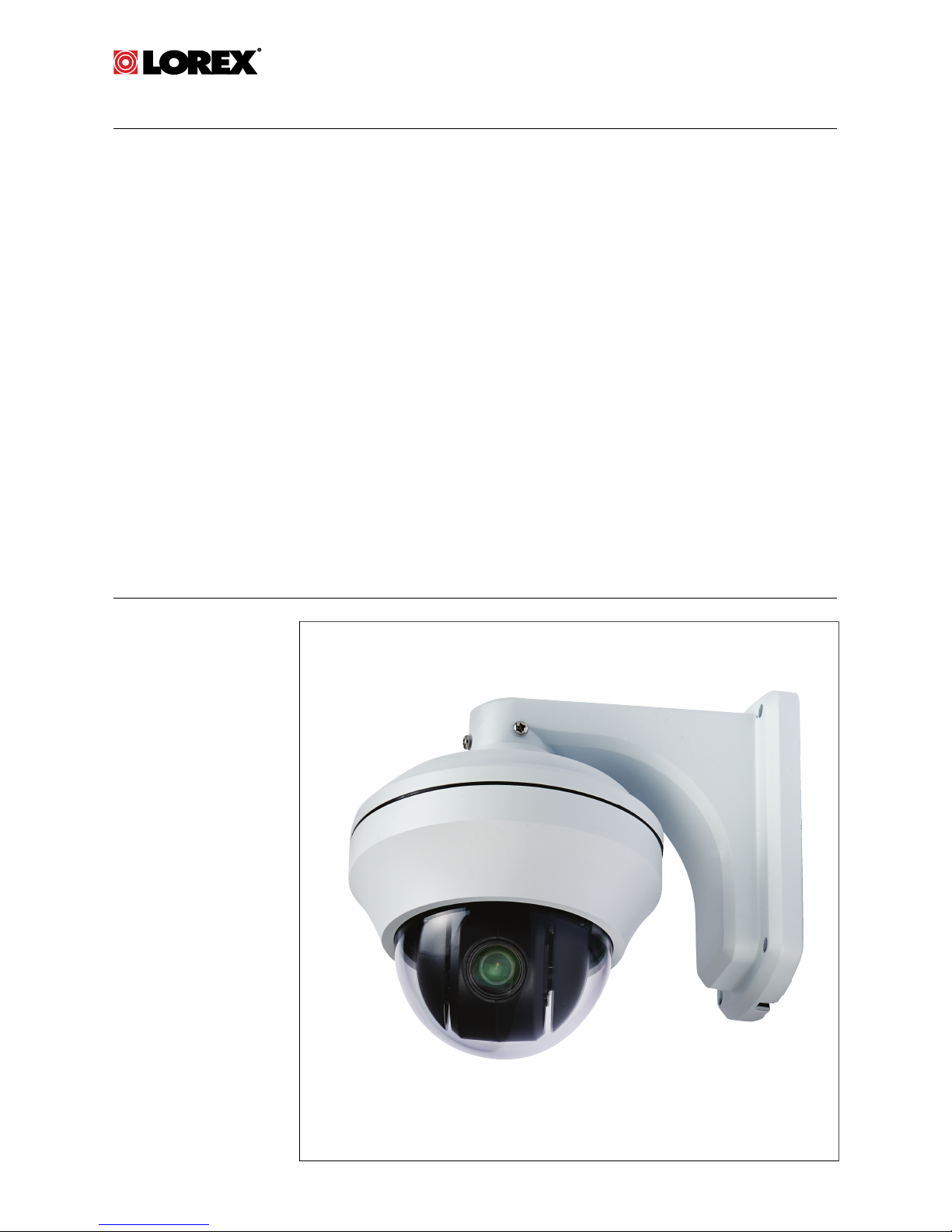
LZC7092B 10X
PTZ Camera
Page 2

Page 3

Instruction Manual
LZC7092B 10X PTZ Camera
#LX400006; r. 1.0/11219/11445; en-US iii
Page 4
Thank you for purchasing this product. Lorex is committed to providing our customers with
a high quality, reliable security solution.
This manual refers to the following models:
LZC7092B
For the latest online manual, downloads and product updates, and to learn about our
complete line of accessory products, please visit our website at:
www.lorextechnology.com
WARNING
RISK OF ELECTRIC SHOCK
DO NOT OPEN
WARNING: TO REDUCE THE RICK OF ELECTRIC SHOCK DO NOT
REMOVE COVER. NO USER SERVICABLE PARTS INSIDE.
REFER SERVICING TO QUALIFIED SERVICE PERSONNEL.
The lightning flash with arrowhead symbol, within an
equilateral triangle, is intended to alert the user to the
presence of uninsulated "dangerous voltage" within the
product’s enclosure that may be of sufficient magnitude to
constitute a risk of electric shock.
The exclamation point within an equilateral triangle is
intended to alert the user to the presence of important
operating and maintenance (servicing) instructions in the
literature accompanying the appliance.
WARNING: TO PREVENT FIRE OR SHOCK HAZARD, DO NOT EXPOSE
THIS UNIT TO RAIN OR MOISTURE.
CAUTION: TO PREVENT ELECTRIC SHOCK, MATCH WIDE BLADE OF
THE PLUG TO THE WIDE SLOT AND FULLY INSERT.
#LX400006; r. 1.0/11219/11445; en-US iv
Page 5

Table of contents
1 Safety Instructions ..............................................................1
2 LZC7092B Features .............................................................2
3 Getting Started ...................................................................3
4 Connecting the Camera .......................................................4
5 Installation .........................................................................6
5.1 Installation Tips and Warnings.......................................6
5.2 Extension Cables .......................................................6
5.2.1 Connection Diagrams for Extending the
Cables Over 100ft............................................ 7
5.3 Installation (Indoor/Outdoor)..........................................9
6 Controlling the PTZ Camera with your DVR........................... 10
6.1 Default Protocol Information........................................ 10
6.2 Initial Setup ............................................................. 10
6.3 Controlling the Camera .............................................. 11
6.4 PTZ Presets and PTZ Cruise....................................... 13
6.4.1 Setting PTZ Presets on the ECO Series
DVR ............................................................14
6.4.2 Selecting PTZ Presets on the ECO Series
DVR ............................................................15
6.4.3 Deleting PTZ Presets on the ECO Series
DVR ............................................................15
6.4.4 Starting / Stopping PTZ Cruise on the ECO
Series DVR ...................................................15
7 Changing PTZ Protocol Information..................................... 16
7.1 Default values of the DIP switches ................................ 16
7.2 Accessing the DIP Switches........................................ 16
7.3 Setting the Camera ID ............................................... 17
7.4 Setting the Camera Protocol and Baud Rate................... 18
8 Technical Specifications .................................................... 19
8.1 Dimensions ............................................................. 20
9 Troubleshooting................................................................ 21
#LX400006; r. 1.0/11219/11445; en-US
v
Page 6

Page 7

Safety Instructions
1
• Read this guide carefully and keep it for future reference.
• Follow all instructions for safe use of the product and handle with care.
• Use the camera within given temperature, humidity, and voltage levels
noted in the Technical Specifications.
• Camera is rated for outdoor use and is weatherproof. Camera is not intended for submersion in water. Installation under a sheltered environment
is recommended.
• Do not disassemble the camera.
• Do not point the camera directly towards the sun or a source of intense
light.
• Use only the supplied regulated power supply. Use of a non-regulated,
non-conforming power supply can damage this product and voids the
warranty.
• Make sure to install the camera in a location that can support the camera
weight.
• Make sure there are no live electrical cables in the area where you plan to
mount the camera.
• Periodic cleaning may be required. Use a damp cloth only. Do not use anything other than water to clean the dome cover, as chemicals such as acetone can permanently damage the plastic.
#LX400006; r. 1.0/11219/11445; en-US
1
Page 8
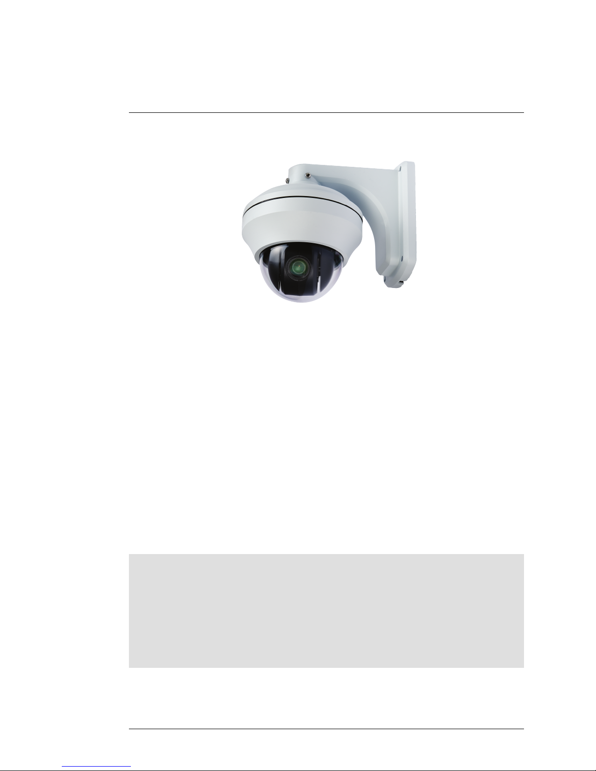
LZC7092B Features
2
• Latest 960H Sony EXview™ II image sensor for excellent low light
performance
1
.
• Sony Effio™ video image processor delivers up to 700TV lines of
resolution.
• 10X Optical Zoom and 10X Digital Zoom to focus in on even the finest
details.
• Complete area coverage with fast 360 degrees per second panning speed.
• Program preset viewing points when connected to a DVR.
• ClearNight technology with Digital Noise Reduction improves low light performance and recording efficiency by up to 30%.
• Accurate colors with Lorex’s automatic light filtering technology.
• Weatherproof (IP66) rated
2
.
• Connects to any Lorex Eco™ or Edge™ series DVR for local or remote
operation.
• 100ft all-in-one extension cable included for installation location flexibility.
Note
1. This camera features an ultra-low light sensitive image sensor and therefore does not
feature Infra-Red LEDs. The camera requires ambient lighting (for example, street/
building lighting, star or moon light) to render a night time image. In total darkness
(zero Lux) the camera will not produce a night time image and therefore the camera
should not be installed in completely dark areas.
2. Not intended for submersion in water. Installation in a sheltered location
recommended.
#LX400006; r. 1.0/11219/11445; en-US
2
Page 9
Getting Started
3
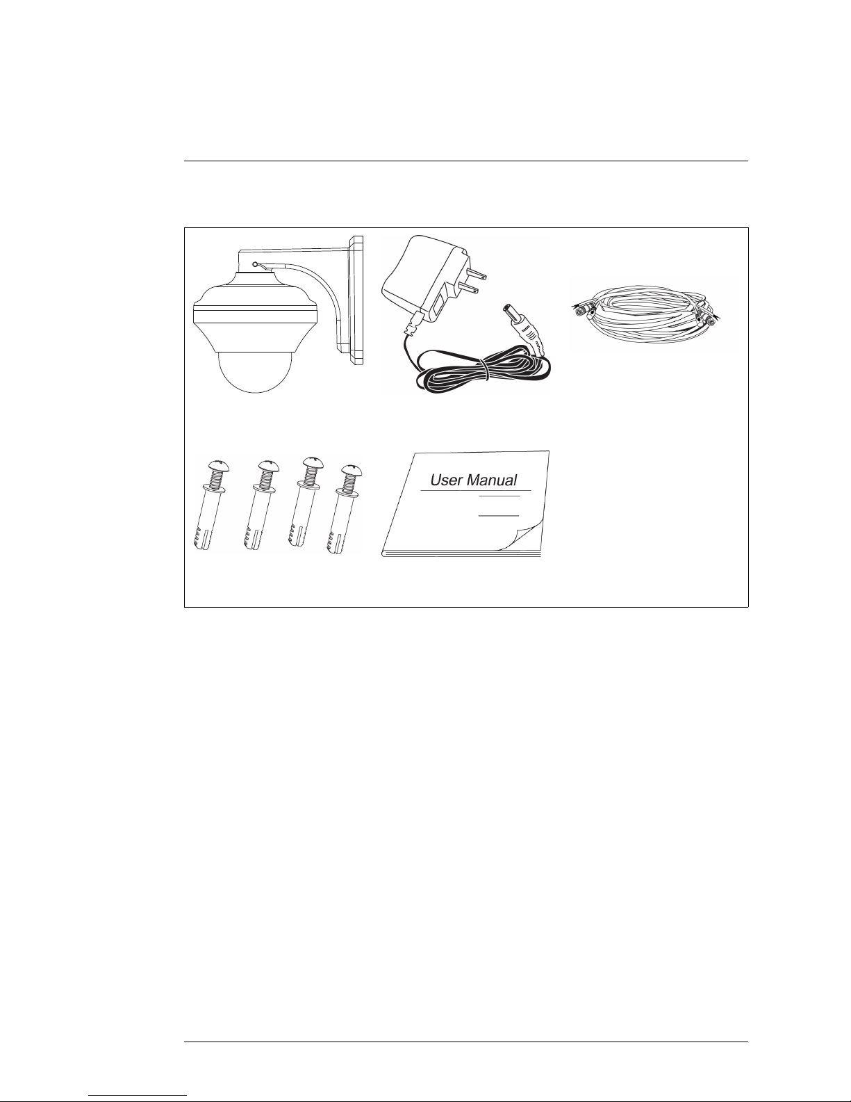
The system comes with the following components:
Camera
13V DC Power Adapter
100ft BNC / Power / RS485
Extension Cable
Mounting Screws and
Anchors
Instruction Manual
#LX400006; r. 1.0/11219/11445; en-US
3
Page 10
Connecting the Camera
4
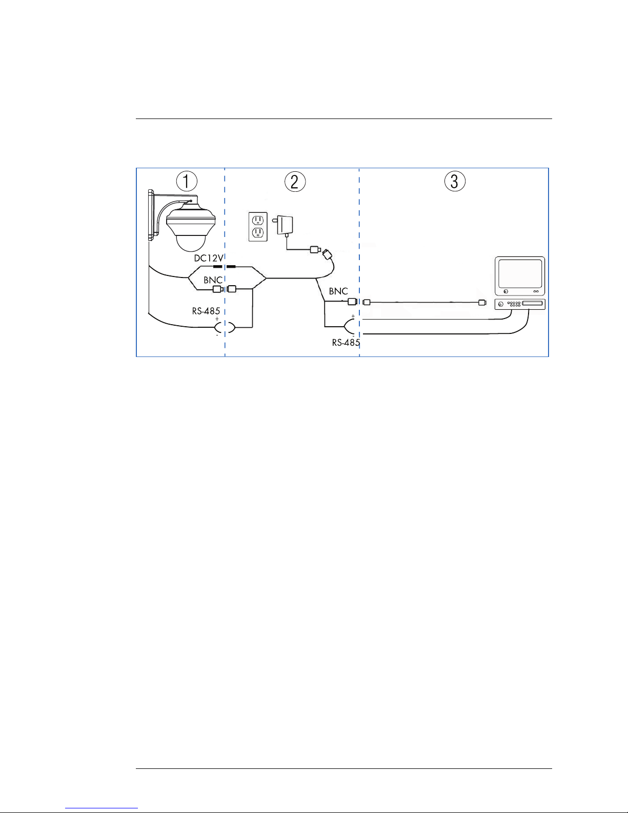
Note
It is recommended to connect the camera to your DVR and test the PTZ controls before
permanent installation. For instructions on how to setup PTZ controls, see 6 Controlling
the PTZ Camera with your DVR, page 10.
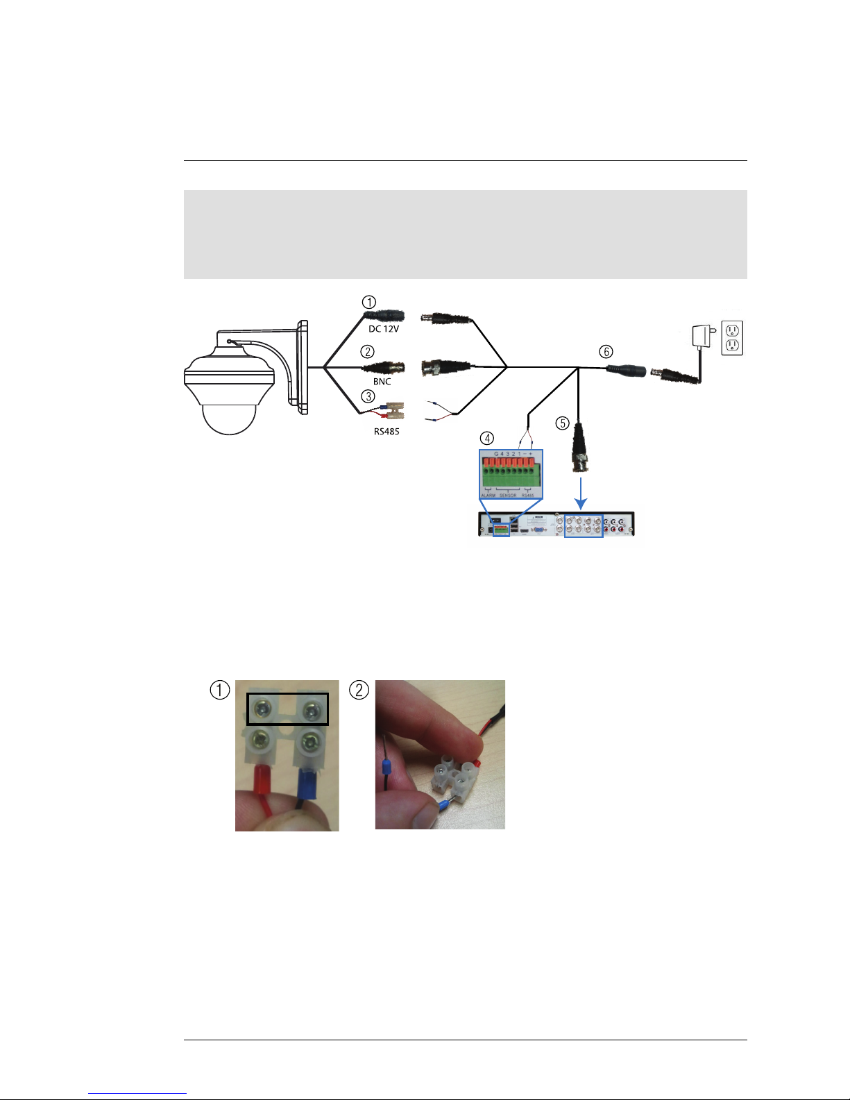
RS485
BNC
DC 12V
1
2
3
4
5
6
1. Connect the female 12V DC power connector on the camera to the male
12V DC power connector on the extension cable.
2. Connect the BNC video connector on the camera to the extension cable.
3. Connect the RS485 wires on the extension cable to the RS485 connector
on the camera as shown below.
0
1 2
3.1. Use a philips head screwdriver (not included) to loosen the 2
screws on the RS485 connection block attached to the camera.
3.2. Insert the RS485 wires on the extension cable, matching the polarity on the cables coming from the camera (red to red, black to
black). Tighten the screws on the RS485 connection block to secure the wires in place.
#LX400006; r. 1.0/11219/11445; en-US
4
Page 11
Connecting the Camera
4
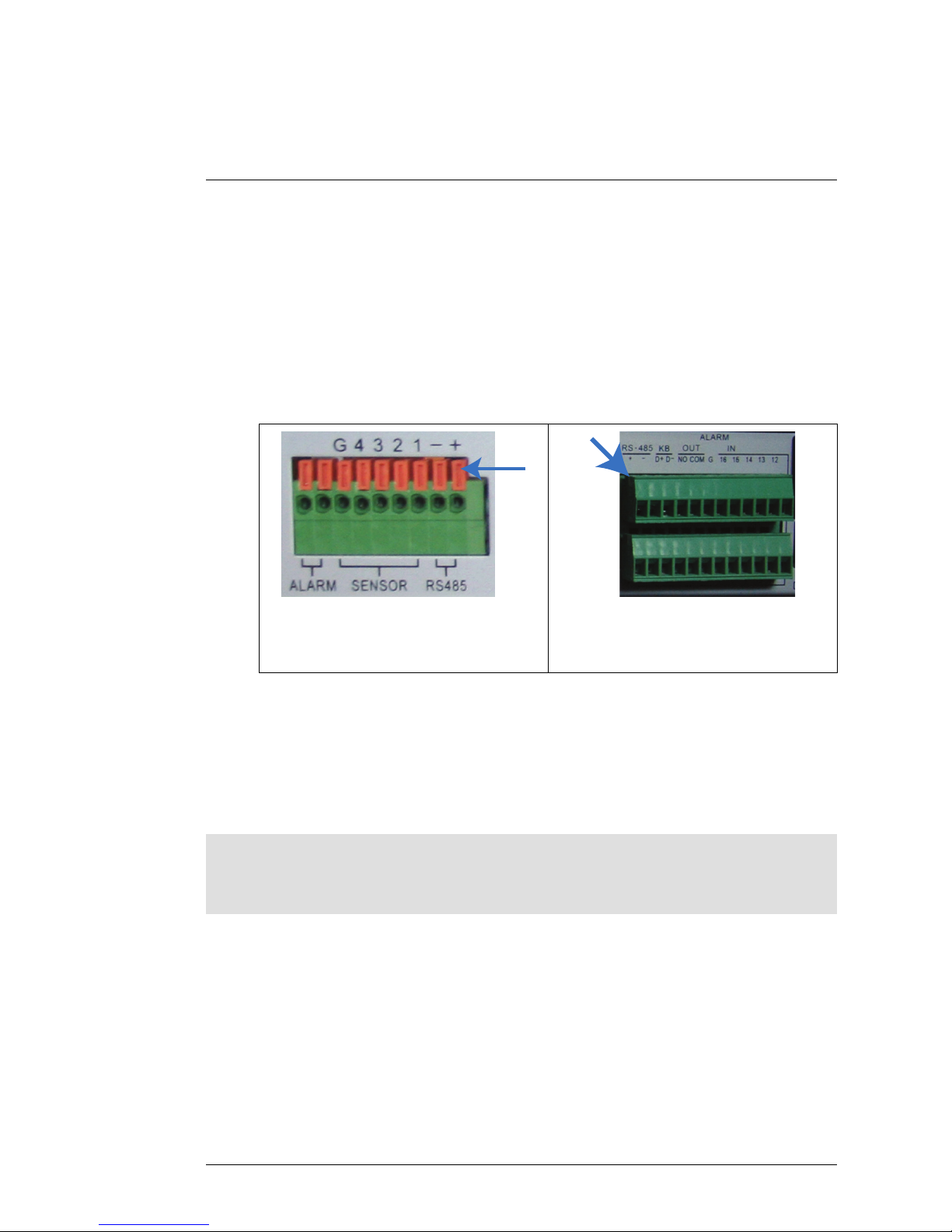
4. Connect the RS485 connectors on the extension cable to the RS485
block on your DVR. The layout of the RS485 block may differ depending
on your DVR model (common terms include RS485, RS422, or PTZ).
• The RS485 connectors are a pair of bare wires. The red wire is positive
(+) and is connected to the + port, and the black wire is negative (-)
and is connected to the - port.
• Most DVRs either use screws or a spring loaded lock to hold the
RS485 wires in place.
Spring loaded alarm block: Insert a
screwdriver into the lock above the port,
and then insert the wires.
Screw lock alarm block: Tighten
screws above ports to secure wires.
5. Connect the BNC cable on the extension cable to one of the Video Input
ports on the DVR. Make note of the port number where you connect the
camera, as it will be used when configuring the DVR to communicate with
the camera.
6. Connect the power connector on the 100ft extension cable to the included
power adapter. Plug the power adapter into a power outlet.
Note
Because this is a high-powered PTZ camera, the power cable cannot be extended beyond
100ft. To extend the BNC video or RS485 cables, see 5.2 Extension Cables, page 6.
#LX400006; r. 1.0/11219/11445; en-US
5
Page 12
Installation
5
5.1 Installation Tips and Warnings
WARNING
Make sure to install the camera in a location that can support the camera weight.
• Camera is rated for outdoor use. It is recommended to install the camera in
a sheltered area, such as under the eaves on a roof.
• It is recommended to install the camera as high up as possible to get the
best possible image.
• Before installing, connect the camera to the DVR and configure the PTZ
protocol information as needed to ensure that you can control the camera
once installed. It is difficult to change the protocol information once the
camera is installed.
• Camera is capable of seeing in extremely low light conditions (0.02 Lux),
but it cannot see in total darkness. It is recommended to install the camera
where there is some ambient light (e.g. street lighting or starlight, moonlight, etc.) or leave some lighting on in the area where the camera is
installed.
• To extend the length of the cable, see 5.2 Extension Cables, page 6.
• Mount the camera where the lens is away from direct and intense sunlight.
• Plan your cable wiring so that it does not interfere with power lines or tele-
phone lines.
• Ensure that the camera wiring is not exposed or easily cut.
• Mount the camera in an area that is visible but out of reach.
Note
This camera is suitable for wall mounting only.
5.2 Extension Cables
• Included extension cable is 100ft / 30m long. If you are planning on extend-
ing the camera beyond 100ft, see 5.2.1 Connection Diagrams for Extend-
ing the Cables Over 100ft, page 7.
• Because this is a high-powered PTZ camera, the power cable cannot be
extended beyond 100ft. You may connect the included power adapter directly to the camera’s power connector and plug the adapter into a power
outlet near the camera. Or, you may connect the power adapter to the end
of the 100ft cable.
#LX400006; r. 1.0/11219/11445; en-US
6
Page 13
Installation
5
• BNC video and PTZ control (RS485) wires can be extended an additional
250ft/76m up to a maximum length of 350ft/106m. Video quality may decrease if your extension cables are too long.
• To extend the BNC video cable beyond 100ft, purchase RG59 coaxial ex-
tension cables. It is recommended to use video cables with the following
specification: RG59U 95% Braid 20AWG or better.
• To extend the PTZ control (RS485) wires beyond 100ft, purchase a pair of
24-gauge wires.
Note
Both RG59 coaxial cable and 24-gauge wires should be available from your local building supply store.
5.2.1 Connection Diagrams for Extending the Cables Over 100ft
Option 1: Connect power adapter near camera.
DVR/TV
Power Adapter
Power
Power
Camera
Extension Cable
BNC
485
+
-
+
-
-
RS-485
BNC
BNC
0
1
2
3
1. Connect power adapter to the camera cable and connect to a nearby
power outlet.
2. Connect extension cable to the BNC and RS485 connectors on the included extension cable.
3. Connect additional video/RS-485 cables to the included extension cable.
Note
The power connectors on the included extension cable will be left unused.
#LX400006; r. 1.0/11219/11445; en-US
7
Page 14
Installation
5
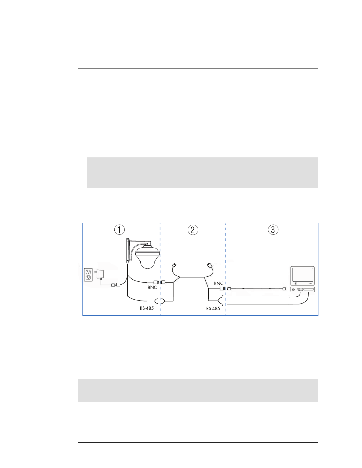
Option 2: Connect power adapter at end of included extension cable.
1
2
3
DVR/TV
Power Adapter
Power
Power
Camera
Extension Cable
BNC
+
-
+
-
-
0
RS-48 5
RS-48 5
BNC
BNC
DC12V
1. Connect camera cable to included extension cable.
2. Connect power adapter to the included extension cable on the side away
from the camera.
3. Connect optional extension cables to the included extension cable.
#LX400006; r. 1.0/11219/11445; en-US
8
Page 15
Installation
5
5.3 Installation (Indoor/Outdoor)
CAUTION
Make sure to disconnect the power adapter before installing the camera. Camera will begin moving immediately when power adapter is connected.
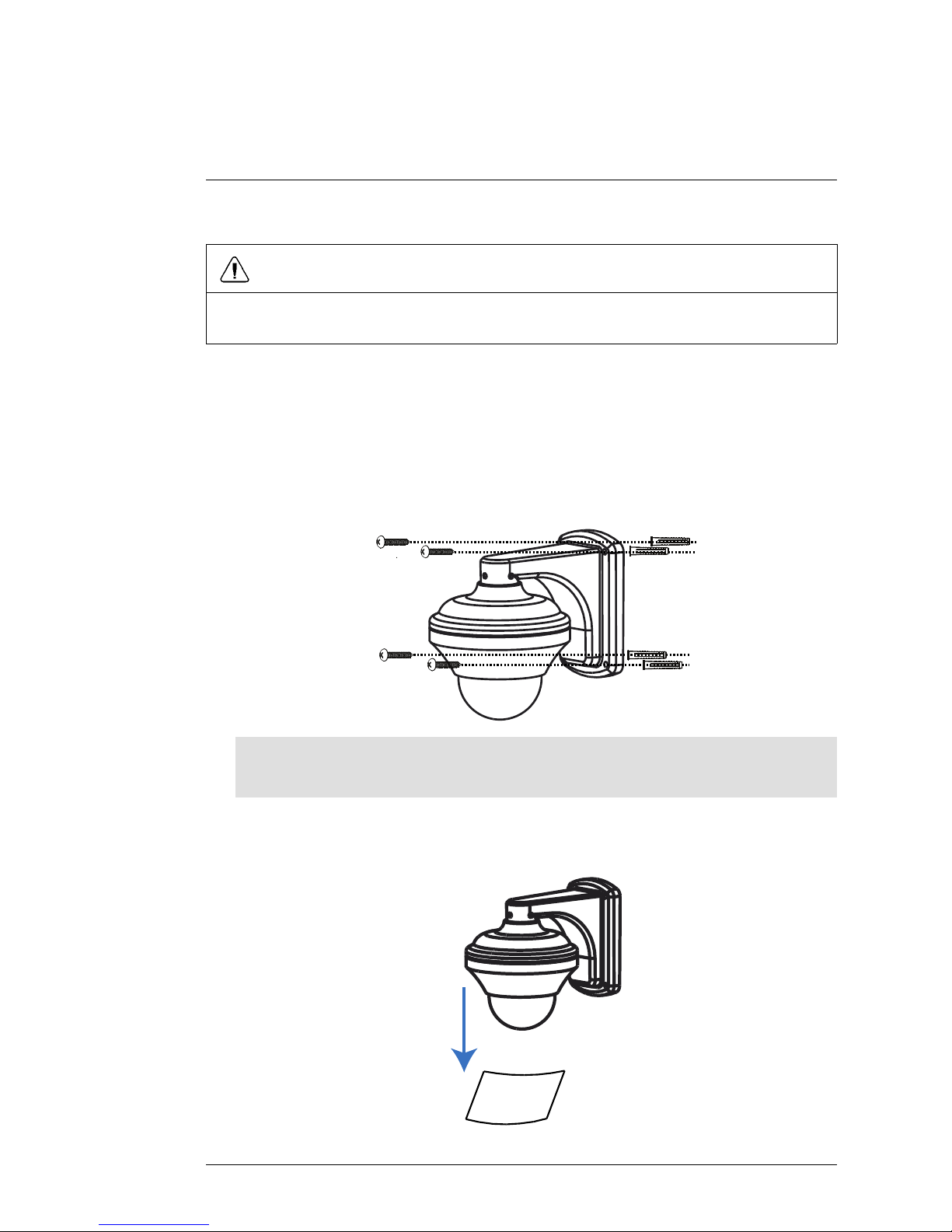
To install the camera:
1. Use the back of the wall mount to mark holes for the wall mount screws
and cable and drill the holes.
2. Connect the cables as shown in 4 Connecting the Camera, page 4.
3. Attach the camera and wall mount to the wall using the included mounting
screws (4x).
Note
Use the included drywall plugs if installing in drywall.
4. Remove protective vinyl sheet from the dome cover once installation is
completed.
#LX400006; r. 1.0/11219/11445; en-US
9
Page 16

Controlling the PTZ Camera
with your DVR
6
Once your camera is connected to the DVR, you must perform initial setup to
control the camera using the DVR. Once this setup is complete, you will be
able to move the camera, configure preset positions, and use other advanced
controls.
PTZ features that are available to you will depend on the model of DVR that
you have. The instructions in this section are based on the Lorex ECO Series
DVRs. For other models, check your DVR’s instruction manual for details.
6.1 Default Protocol Information
Unlike standard security cameras, PTZ (pan-tilt-zoom) cameras require special protocol (language) information to enable a Security DVR to control the
camera movement.
Input the following information into your DVR to enable PTZ controls.
• Default ID: 1.
• Default Baud Rate: 9600.
• Default Protocol: Pelco-D.
You will not need to change the default protocol information on your camera
unless you are using multiple PTZ cameras or if your DVR does not support
the default settings (see your DVR’s instruction manual for details). If you need
to change the PTZ protocol information, 7 Changing PTZ Protocol Information,
page 16.
6.2 Initial Setup
In the initial setup process, you will input the camera’s protocol information into your DVR. This enables PTZ functionality.
Note
The camera will display the configured PTZ protocol information when it starts up. To
quickly display this information on the monitor, disconnect and reconnect the camera
power adapter.
To perform initial setup using a Lorex ECO Series DVR:
1. Ensure the cables are connected correctly to the DVR according to 4 Connecting the Camera, page 4.
#LX400006; r. 1.0/11219/11445; en-US
10
Page 17
Controlling the PTZ Camera with your DVR
6
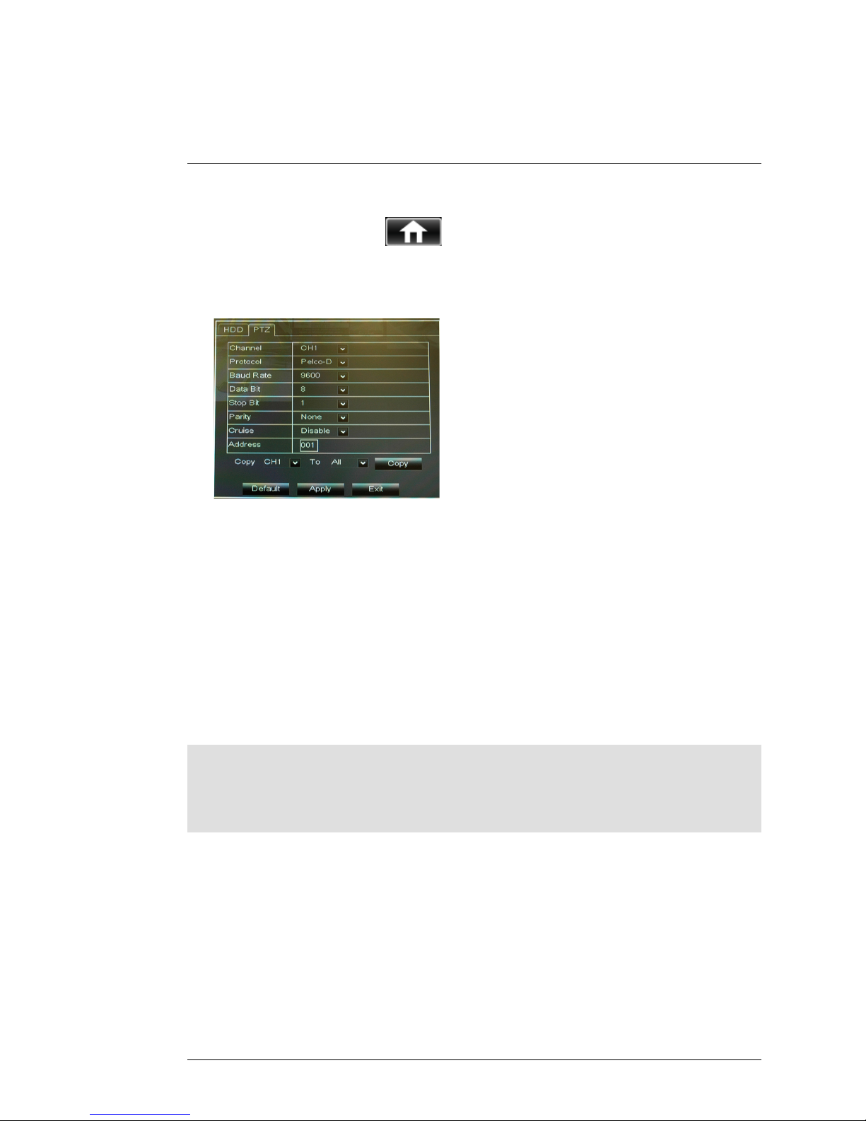
2. On the DVR, Right-click with the mouse to open the Menu Bar and click
the Main Menu button (
).
3. Click Device and select the PTZ tab.
4. Configure the following:
• Channel: Select the channel that you connected the PTZ camera to.
• Protocol: Select the protocol (default: Pelco-D).
• Baud rate: Select the camera’s baud rate (default: 9600).
• Data Bit: Select 8.
• Stop Bit: Select 1.
• Parity: Select None.
• Cruise: Select Enable to enable PTZ cruise.
• Address: Enter the camera’s ID (default: 001).
5. Click Apply to save your settings.
6.3 Controlling the Camera
Note
Turn off motion detection on your DVR for the channel with the PTZ camera connected.
Otherwise, the DVR will detect the PTZ movement as motion. See your DVR’s instruction
manual for details.
To control the PTZ camera locally on the ECO Series DVR:
1. Select the channel that the PTZ camera is connected to.
#LX400006; r. 1.0/11219/11445; en-US
11
Page 18
Controlling the PTZ Camera with your DVR
6
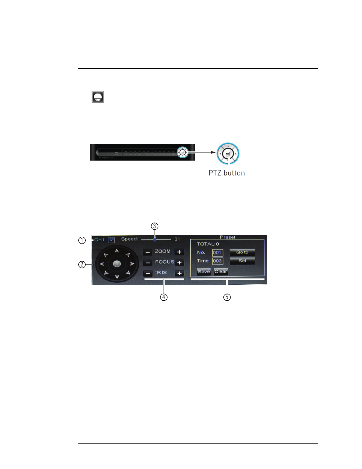
2. Right-click with the mouse to open the Menu Bar and click the PTZ button
(
).
OR
Press and hold the PTZ button on the front panel of the system for 6
seconds.
3. Enter the DVR password (default: 000000) and click Apply.
4. Use the on-screen PTZ controls to control the camera.
PTZ Controls
1
2
3
4 5
1. Channel: Select the channel the PTZ camera is connected to.
2. Direction Keys: Click to pan and tilt the camera.
3. Speed Slider: Increase or decrease the pan and tilt speed.
4. Zoom/Focus/Iris Controls.
5. Preset Controls
#LX400006; r. 1.0/11219/11445; en-US
12
Page 19
Controlling the PTZ Camera with your DVR
6
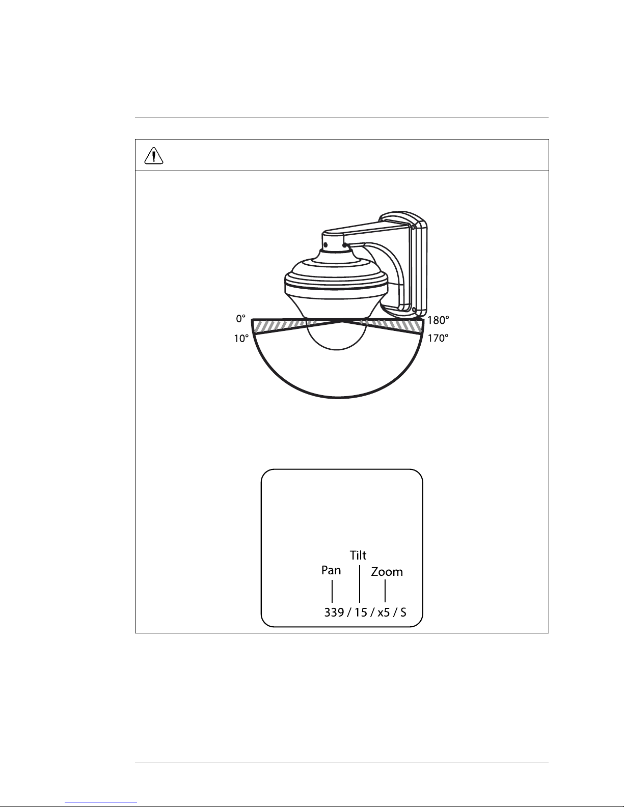
CAUTION
This PTZ camera is designed to tilt up and down within a range of 160°. Tilting less than
10° or greater than 170° may cause the edge of the image to become slightly unclear.
180°
0°
170°
10°
White area shows the optimal tilt range of the camera.
If this happens, use the DVR controls to tilt the camera between 10° and 170°. The camera’s tilt angle appears on the monitor when it moves.
339 / 15 / x5 / S
Pan
Tilt
Zoom
6.4 PTZ Presets and PTZ Cruise
Using the DVR, you can create presets. Presets allow you to save different positions of the camera, so you can return the camera to these positions quickly
without using the manual controls.
#LX400006; r. 1.0/11219/11445; en-US
13
Page 20
Controlling the PTZ Camera with your DVR
6
A PTZ cruise (referred to on some DVR’s as a tour or scan), allows you to configure a sequence of presets that the camera will automatically cycle through.
This is useful if you want the camera to monitor a large area, without manually
having to control the camera.
Note
These features may not be available on all DVRs. Check your DVR instruction manual for
details.
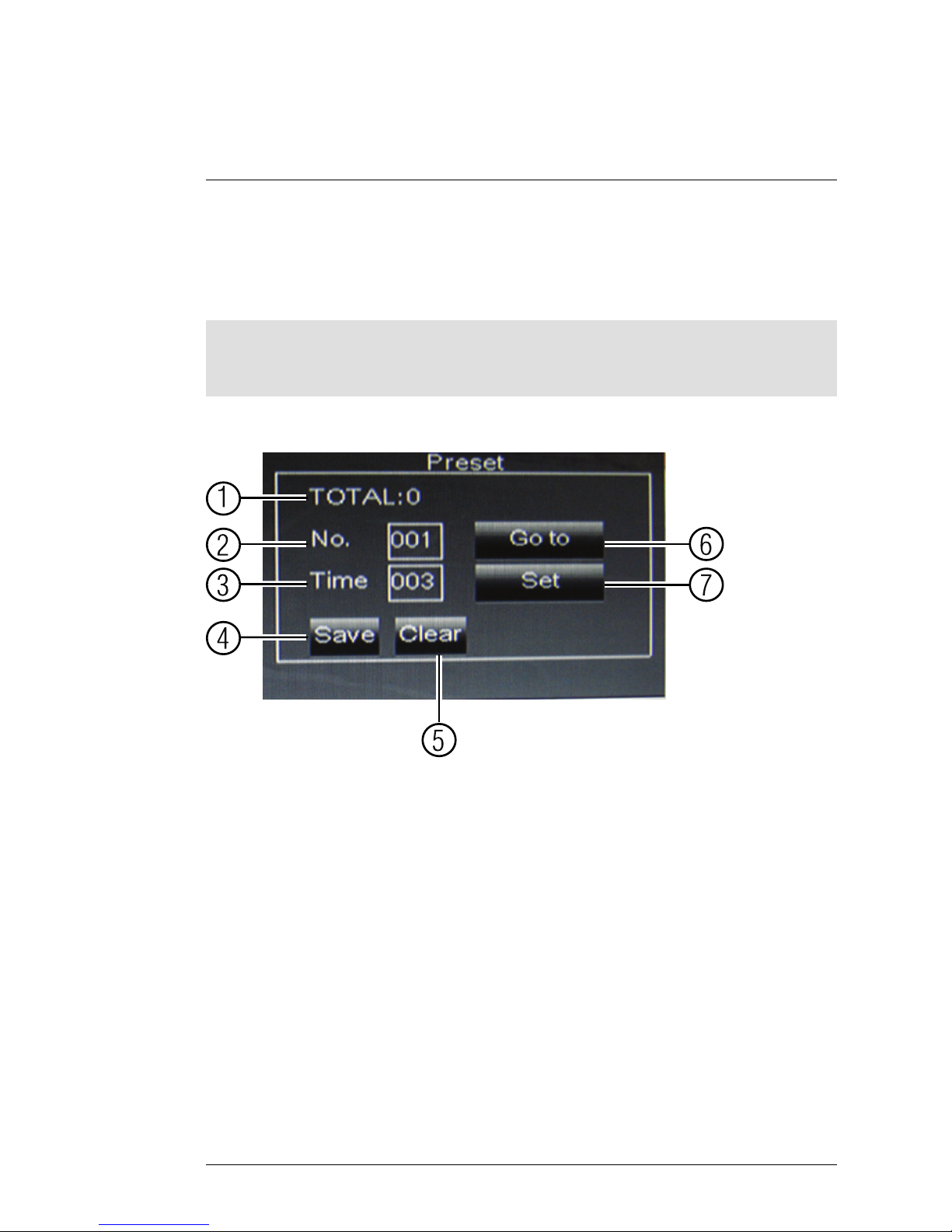
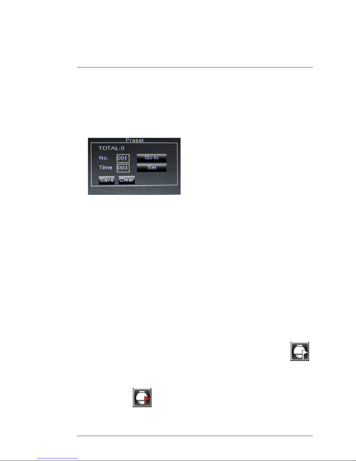
Preset Controls on ECO Series DVRs
0
1
2
3
4
5
6
7
1. Total: Total number of presets.
2. No.: Shows the number of the currently selected preset. Enter the desired
preset number to select or configure a different preset.
3. Time: When cruise mode is activated, the time field determines how long
the camera will hold at the preset position before moving to the next preset. When creating presets, enter the number of seconds the camera will
stay at the preset.
4. Save: Click to save all changes made to presets.
5. Clear: Click to delete the currently selected preset.
6. Go to: Click to go to the currently selected preset.
7. Set: Click to save the current camera position as a preset.
6.4.1 Setting PTZ Presets on the ECO Series DVR
1. Using the direction keys, zoom, focus, and iris settings, move the camera
into position.
#LX400006; r. 1.0/11219/11445; en-US
14
Page 21
Controlling the PTZ Camera with your DVR
6
2. (Optional) In the Time field, select the number of seconds the camera will
remain in that position during PTZ cruise before going to the next position.
3. Click Set to set the preset. The Total and No. fields will automatically increase. The Total field shows you the total number of created presets, and
the No. field shows you the number of the preset you are currently
creating.
4. Repeat the steps above to create additional presets as needed. Press
Save when you are finished to save all created presets.
6.4.2 Selecting PTZ Presets on the ECO Series DVR
1. In the No. field, select the number of the preset you would like to select.
2. Click Go to to go to the preset.
6.4.3 Deleting PTZ Presets on the ECO Series DVR
1. In the No. field, select the number of the preset you would like to delete.
2. Click Clear to delete the preset, and click Save to save your changes.
6.4.4 Starting / Stopping PTZ Cruise on the ECO Series DVR
When PTZ cruise is enabled, the camera will cycle through saved presets.
You must set and save presets to use PTZ cruise.
To start / stop PTZ cruise on the ECO Series DVR:
1. Right-click to exit PTZ menu.
2. Right-click to open the Menu Bar and click the Start Cruise button (
).
Enter the DVR password (default: 000000). The camera will cycle through
PTZ presets.
3. To stop the PTZ cruise, right-click to open the Menu Bar and click the Stop
Cruise button (
). Enter the DVR password (default: 000000).
#LX400006; r. 1.0/11219/11445; en-US
15
Page 22
Changing PTZ Protocol
Information
7
The camera’s PTZ protocol information allows a DVR to communicate with it
and control the camera’s movement.
Note
You will not need to change the default protocol information on your camera unless you
are using multiple PTZ cameras or if your DVR does not support the default settings (see
your DVR’s instruction manual for details).
PTZ protocol information on this camera is set using DIP switches inside the
camera. DIP switches represent binary values. This means that they are either
On (1) or Off (0).
The DIP switches control 3 values:
1. The ID of the camera, which allows the DVR to identify different PTZ
cameras.
2. The protocol, which is the language that allows the camera and DVR to
speak to each other (e.g. Pelco D).
3. The baud rate, which is the frequency of communications.
7.1 Default values of the DIP switches
• Default ID: 1.
• Default Baud Rate: 9600.
• Default Protocol: Pelco-D.
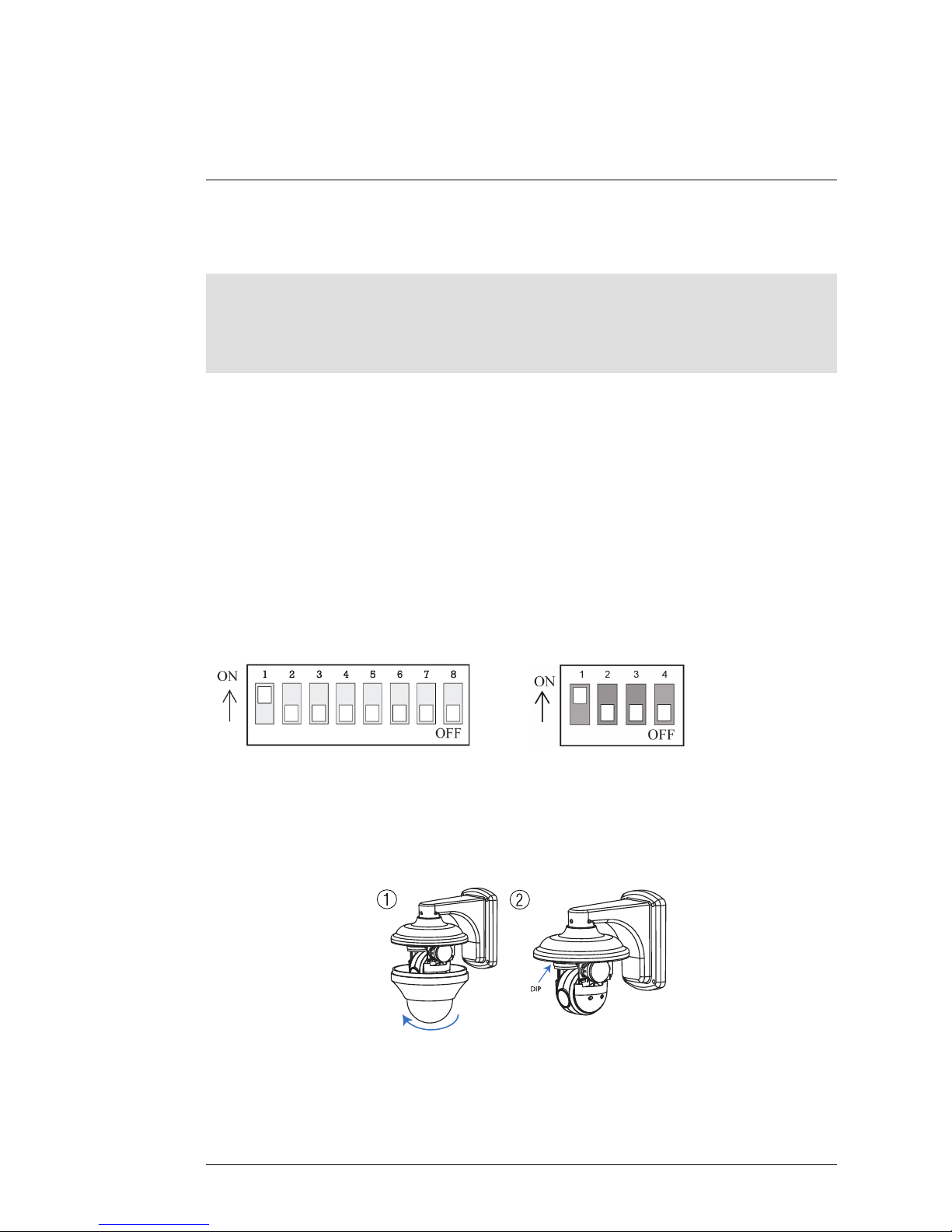
7.2 Accessing the DIP Switches
1
2
DIP
1. Rotate the dome cover counterclockwise to remove it from the camera.
2. The DIP switches are located below the camera module.
#LX400006; r. 1.0/11219/11445; en-US
16
Page 23
Changing PTZ Protocol Information
7
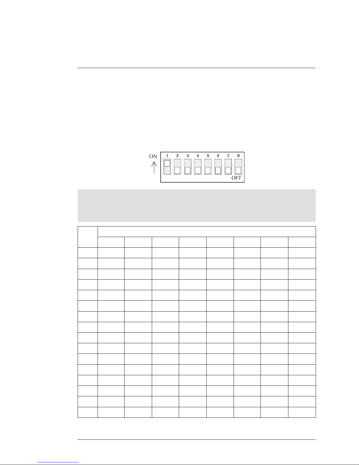
7.3 Setting the Camera ID
The camera ID is how the DVR identifies PTZ cameras.
Camera ID is set using the larger DIP switch panel with 8 switches. Each
switch represents a binary digit (i.e. switch #1=1, #2=2, #3=4, etc.). Camera
ID can be anything between 1-255. See the address example table.
Camera ID DIP switches
Note
You cannot use the same ID for more than 1 PTZ camera.
You cannot set an ID with a value of 0.
ID
Switch is ON or OFF
1 2 3 4 5 6 7 8
1
ON OFF OFF OFF OFF OFF OFF OFF
2
OFF ON OFF OFF OFF OFF OFF OFF
3
ON ON OFF OFF OFF OFF OFF OFF
4
OFF OFF ON OFF OFF OFF OFF OFF
5
ON OFF ON OFF OFF OFF OFF OFF
6
OFF ON ON OFF OFF OFF OFF OFF
7
ON ON ON OFF OFF OFF OFF OFF
8
OFF OFF OFF ON OFF OFF OFF OFF
9
ON OFF OFF ON OFF OFF OFF OFF
10
OFF ON OFF ON OFF OFF OFF OFF
11
ON ON OFF ON OFF OFF OFF OFF
12
OFF OFF ON ON OFF OFF OFF OFF
13
ON OFF ON ON OFF OFF OFF OFF
14
OFF ON ON ON OFF OFF OFF OFF
15
ON ON ON ON OFF OFF OFF OFF
16
OFF OFF OFF OFF ON OFF OFF OFF
#LX400006; r. 1.0/11219/11445; en-US
17
Page 24
Changing PTZ Protocol Information
7
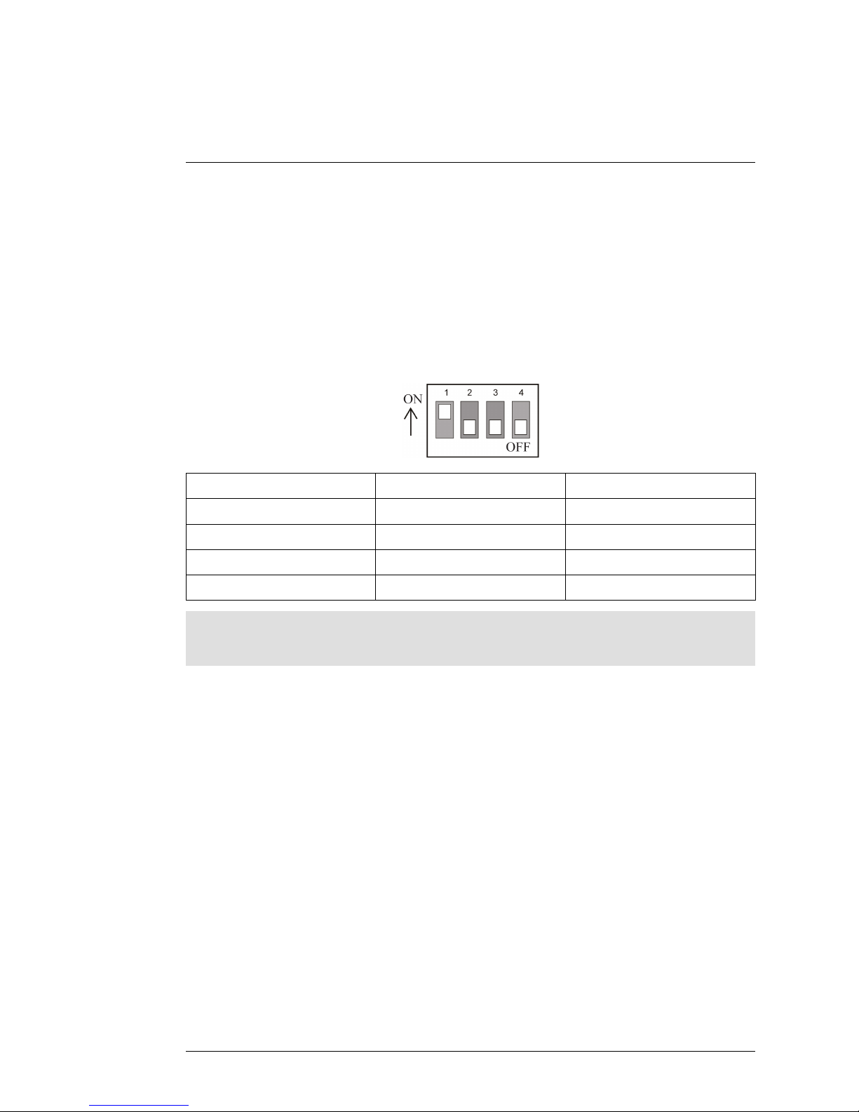
7.4 Setting the Camera Protocol and Baud Rate
The protocol is the language that allows the camera and DVR to communicate, and the baud rate is the frequency of signal sent to the camera. The
camera supports Pelco-D and Pelco-P protocols.
Protocol and baud rate are set using switches 1 and 2 on the smaller DIP
switch panel. See the table below.
Protocol and baud rate switches
1 2
Protocol/Baud Rate
OFF OFF Pelco-D 2400
ON OFF Pelco-D 9600
OFF ON Pelco-P 4800
ON ON
Pelco-P 9600
Note
Switches 3 and 4 are for manufacturer use only and should always be set to OFF.
#LX400006; r. 1.0/11219/11445; en-US
18
Page 25

Technical Specifications
8
Image Sensor 1/3" 960H Sony Ex-View HAD CCD II
Video Format
NTSC
Effective Pixels 976(H) x 494 (V)
Resolution Up to 700 TVL
Range 360° Pan (Endless)160° Tilt (Auto-Flip)
Pan/Tilt Speed Max 360°/Sec.
Zoom 10x Optical Zoom & 10x Digital Zoom
Protocol Pelco-D, Pelco-P
Min. Illumination
0.7 Lux in Color 0.02 Lux in Black and White
Lens / Lens Type Auto Focus / 3.8-38mm F1.8
S / N Ratio 50db (AGC Off)
Iris Auto Iris
Termination
BNC Video / RS485 / DC Power
Video Output Composite 1.0Vpp @ 75ohm
Power Requirement 12V DC ±10%
Power Consumption
Max. 850mA
Operating Temperature Range -4°F ~ 122°F / -20°C ~ 50°C
Operating Humidity Range within 90%RH
Indoor/Outdoor Both (IP66)
1
Weight (Camera & Wall Mount) 2.9lbs / 1.3kg
#LX400006; r. 1.0/11219/11445; en-US
19
1. Not intended for submersion in water. Installation in a sheltered location recommended.
Page 26
Technical Specifications
8
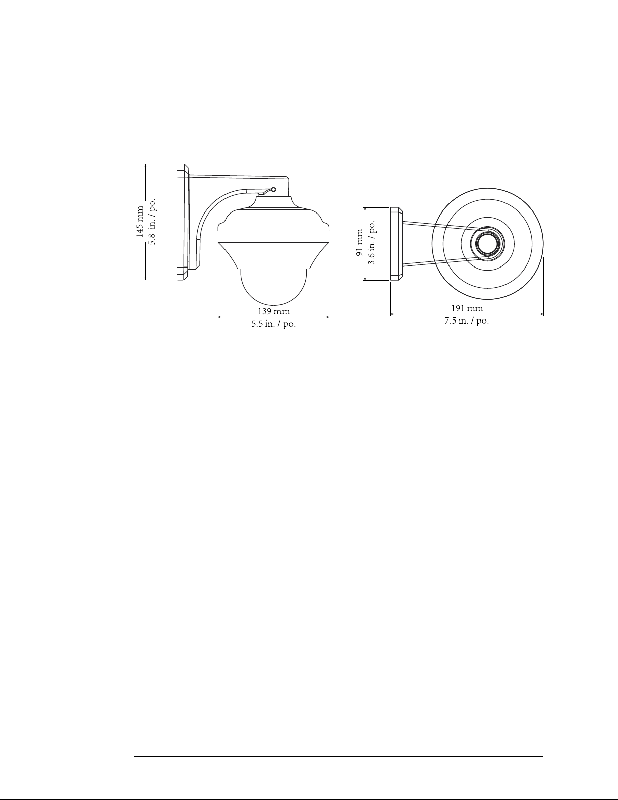
8.1 Dimensions
NN NN
JJ OO QQ PP
NNN
N
JJOOQQPP
NNN
N
JJOOQQPP
N
N
N
N
J
J
O
O
Q
Q
P
P
#LX400006; r. 1.0/11219/11445; en-US
20
Page 27

Troubleshooting
9
There is no picture at night.
• Camera is capable of seeing in extremely low light conditions (0.02 Lux),
but it cannot see in total darkness. It is recommended to install the camera
where there is some ambient light (e.g. street lighting, starlight, moonlight,
etc.) or leave a light on in the area where the camera is installed.
No image at startup.
• Check to ensure your camera is properly connected (see 4 Connecting the
Camera, page 4) and the power adapter is plugged in.
• Connect the power adapter to a different outlet.
• Make sure power adapter is the original one provided. Do not use other
power adapters with this product, as this will void the warranty.
No image or camera image is unclear.
• Dome cover is dirty. Clean the dome cover with a soft, slightly damp cloth.
Do not use anything other than water to clean the dome cover, as chemicals such as acetone can permanently damage the plastic.
• Extension cable run may be too long (see 5.2 Extension Cables, page 6 for
details).
• Voltage may drop over distance and affect image quality. The power adapt-
er must be connected either at the end of the provided 100ft cable or directly to the 3ft cable.
Image is distorted.
• Image may become unclear when camera is tilted too close to the camera
base (e.g. pointed parallel to the ceiling). Tilt the camera using DVR PTZ
controls.
PTZ controls are not working or are not working properly.
• RS485 wires not connected or connected using wrong polarity. Ensure the
red wire is connected to the + RS485 port and the black wire is connected
to the - RS485 port.
• Not enough of RS485 wire is exposed to make proper connection. Use a
wire stripper (not included) to strip off some of the wire insulation.
• Extension cables may be damaged or are not connected properly. Check
your extension cable run.
• PTZ protocol details are not configured in DVR. See your DVR instruction
manual for details.
#LX400006; r. 1.0/11219/11445; en-US
21
Page 28

Troubleshooting
9
• Multiple PTZ cameras are using the same camera ID. This will either dis-
able or affect PTZ controls. Configure a separate camera ID for each camera (see 7 Changing PTZ Protocol Information, page 16 for details).
DVR motion detection is constantly triggering.
• Turn off motion detection on the channel the PTZ camera is connected to.
DVR’s use video motion detection, which means they detect motion by
looking for changes between frames (images) in the video. If the camera is
moving, the DVR will detect this as motion.
#LX400006; r. 1.0/11219/11445; en-US
22
Page 29

Page 30

last page
Publ. No.: LX400006
Release: 1.0
Commit:
11219
Head: 11445
Language: en-US
Modified: 2014-01-28
Formatted: 2014-02-07
Website
www.lorextechnology.com
Copyright
© 2014, Lorex Corporation
All rights reserved worldwide. Names and marks appearing herein are either registered trademarks or
trademarks of Lorex Corporation and/or its subsidiaries. All other trademarks, trade names or company
names referenced herein are used for identification only and are the property of their respective owners.
Legal disclaimer
As our product is subject to continuous improvement, Lorex Corporation & subsidiaries reserve the right to
modify product design, specifications & prices without notice and without incurring any obligation.E&OE.
Page 31

Manuel
d'utilisation
Caméra
LZC7092B 10X
PTZ
Page 32

Page 33

Manuel d'utilisation
Caméra LZC7092B 10X PTZ
#LX400006; r. 1.0/11447/11448; fr-CA iii
Page 34

Merci pour l'achat de ce produit. Lorex s'engage à fournir aux clients une solution de
sécurité fiable et de haute qualité.
Ce manuel fait référence aux modèles suivants :
LZC7092B
Pour le manuel en ligne le plus récent, les téléchargements, mises à jour du produit et
pour en savoir plus sur notre gamme complète d'accessoires, veuillez visiter notre site
Web :
www.lorextechnology.com
AVERTISSEMENT :
RISQUE
D'ÉLECTROCUTION
NE PAS OUVRIR
AVERTISSEMENT: POUR RÉDUIRE LE RISQUE D'ÉLECTROCUTION,
NE RETIREZ PAS LE COUVERCLE. LES PIÈCES INTERNES NE SONT
PAS RÉPARABLES PAR L'UTILISATEUR.
ADRESSEZ-VOUS À UN TECHNICIEN QUALIFIÉ.
Le symbole d'éclair fléché dans un triangle équilatéral est
destiné à alerter l'utilisateur de la présence d'une « tension
dangereuse » non isolée dans le boîtier du produit pouvant
être d'amplitude suffisante pour constituer un risque
d'électrocution.
Le point d'exclamation dans un triangle équilatéral est
destiné à alerter l'utilisateur de la présence d'importantes
instructions d'utilisation et de maintenance (entretien) dans
la documentation qui accompagne l'appareil.
AVERTISSEMENT: POUR PRÉVENIR TOUT RISQUE D'INCENDIE OU
D'ÉLECTROCUTION, N'EXPOSEZ PAS CET APPAREIL À LA PLUIE OU
L'HUMIDITÉ.
#LX400006; r. 1.0/11447/11448; fr-CA iv
Page 35

MISE EN GARDE: POUR ÉVITER LES DÉCHARGES ÉLECTRIQUES,
JUMELEZ LA LAME LARGE DE LA FICHE À LA FENTE LARGE ET
INSÉREZ COMPLÈTEMENT.
#LX400006; r. 1.0/11447/11448; fr-CA
v
Page 36

Page 37

Tables des matières
1 Mesure de sécurité..............................................................1
2 Les caractéristiques LZC7092B ............................................2
3 La mise en route .................................................................4
4 Installation de la caméra ......................................................5
5 Installation .........................................................................7
5.1 Les conseils et les avertissements d'installation.................7
5.2 Les rallonges .............................................................7
5.2.1 Schéma d'interconnexion pour étendre les
câbles de plus de 100ft (30m) ............................ 8
5.3 L'installation (Intérieur/extérieur) .................................. 10
6 Commander la caméra PTZ avec votre DVR .......................... 12
6.1 Information par défaut du protocole .............................. 12
6.2 La configuration initiale ............................................. 12
6.3 Commander la caméra .............................................. 13
6.4 La présélection PTZ et le déplacement PTZ ................... 15
6.4.1 Le réglage des présélections PTZ sur les
séries DVR ECO ............................................17
6.4.2 Sélectionner les présélections PTZ sur les
séries DVR ECO ............................................17
6.4.3 Supprimer les présélections PTZ sur les
séries DVR ECO ............................................17
6.4.4 Commencer/Arrêter le déplacement PTZ sur
les séries ECO DVR........................................17
7 Changer l'information du protocole PTZ .............................. 19
7.1 Les valeurs par défaut des interrupteurs DIP................... 19
7.2 Accès aux interrupteurs DIP........................................ 19
7.3 Régler l'ID (Identificateur de périphérique) de la
caméra ...................................................................21
7.4 Régler le protocole de la caméra et le débit en
bauds ....................................................................24
8 Les spécifications techniques ............................................ 25
8.1 Dimensions ............................................................. 26
9 Dépannage....................................................................... 27
#LX400006; r. 1.0/11447/11448; fr-CA vii
Page 38

Page 39

Mesure de sécurité
1
• Lire attentivement ce guide et le garder pour consultation ultérieure
• Suivre toutes les instructions pour une bonne utilisation et manipuler avec
attention
• Utiliser la caméra à la température spécifiée, au taux d'humidité et niveau
de tension affichés dans les caractéristiques techniques.
• La caméra est conçue pour un usage extérieur et pour les intempéries. Ne
pas immerger dans l'eau. L'installation est recommandée dans un endroit
couvert.
• Ne pas démonter la caméra.
• Ne pas pointer votre caméra vers le soleil ou une source intense de
lumière.
• Utiliser seulement l'alimentation régulée fournie. L'utilisation d'une alimentation non-régulée et non conforme peut endommager ce produit et annuler la garantie.
• Assurez-vous d'installer la caméra dans un endroit pouvant supporter le
poids de la caméra.
• Assurez-vous qu'il n'y est pas de câbles électriques sous tension à l'endroit
ou vous prévoyez de fixer la caméra.
• Un nettoyage périodique peut s'avérer nécessaire. Utiliser seulement un
linge humide. Ne pas utiliser autre chose que de l'eau pour nettoyer le couvercle du dôme, comme par exemple les produits chimiques tel que les
solvants qui peuvent endommager le plastique de manière permanente.
#LX400006; r. 1.0/11447/11448; fr-CA
1
Page 40

Les caractéristiques
LZC7092B
2
• Le dernier 960H Sony EXview™ II avec un capteur d'image pour une excellente performance nocturne
1
.
• Processeur d'image vidéo produisant jusqu'à 700 lignes de résolution
• Zoom optique 10X et zoom numérique 10X pour une mise au point rapproché même sur les plus petits détails.
• Pour couvrir entièrement des zones étendues avec une vitesse de zoom
rapide à 360 degrés.
• Sélectionner le programme de visionnage des points quand il est connecté
au DVR.
• La technologie de Lorex ClearNight avec réduction du bruit numérique
améliore les performances de faibles éclairages et l'efficacité d'enregistrement jusqu'à 30 %.
• Couleurs précises grâce à la technologie de filtrage automatique de luminosité de Lorex.
• Résistant aux intempéries (IP66) est évalué
2
.
• Se connecte à n'importe quelles séries DVR Lorex Eco™ ou Edge™ pour
un fonctionnement local ou à distance.
• 100ft (30m) de câble inclus tout-en-un pour une flexibilité du lieu
d'installation.
#LX400006; r. 1.0/11447/11448; fr-CA
2
Page 41

Les caractéristiques LZC7092B
2
REMARQUE
1. Cette caméra tire avantage d'un capteur sensible d'images à faible luminosité et par
conséquent n'a pas la fonctionnalité de la LED Infra-rouge. La caméra nécessite une
luminosité ambiante (par exemple, lumière de rue/immeuble, lumière des étoiles ou
de la lune) pour générer une image de nuit. Dans l'obscurité totale (Lux zéro) la caméra ne générera pas une image de nuit et par conséquent la caméra ne devrait pas être
installée dans des endroits totalement obscures.
2. Ne pas immerger dans l'eau. Installation recommandée dans un emplacement
couvert.
#LX400006; r. 1.0/11447/11448; fr-CA
3
Page 42

La mise en route
3
Le système est livré avec les éléments suivants :
La caméra Bloc d'alimentation 13V DC
100ft (30m) BNC
câble de rallonge
Les vis de montage et les
ancrages
Manuel d'utilisation
#LX400006; r. 1.0/11447/11448; fr-CA
4
Page 43

Installation de la caméra
4
REMARQUE
Il est recommandé de brancher la caméra au DVR et de tester les contrôles PTZ avant
l'installation permanente. Pour plus d'informations sur la configuration des commandes
PTZ, voir 6 Commander la caméra PTZ avec votre DVR, page 12.
RS485
BNC
DC 12V
1
2
3
4
5
6
1. Brancher le connecteur d’alimentation femelle 12V DC à la caméra, le
connecteur d’alimentation male 12V DC à la rallonge.
2. Brancher le connecteur vidéo BNC de la caméra sur la rallonge.
3. Branchez les câbles RS485 sur la rallonge, le connecteur RS485 à la caméra tel qu'illustré ci-dessous.
0
1 2
3.1. Utiliser le tournevis à tête Philips (non inclus) pour desserrer les
deux vis sur le bloc de connexion RS485 fixé à la caméra.
3.2. Insérer les câbles RS485 sur la rallonge, en respectant la polarité
des câbles en provenance de la caméra (rouge à rouge, noir à
noir). Serrer les vis sur le bloc de connexion RS485 afin de fixer les
câblages correctement.
#LX400006; r. 1.0/11447/11448; fr-CA
5
Page 44

Installation de la caméra
4
4. Brancher les connecteurs RS485 de la rallonge au bloc RS485 sur votre
DVR. La présentation du bloc RS485 peut différer en fonction de votre
modèle DVR (termes courants inclus RS485, RS422, ou PTZ).
• Les connecteurs RS485 sont une paire de câbles nus. Le câble rouge
est positif (+) et connecté au + port, et le fil noir est négatif (-) et
connecté au - port.
• La plupart des DVR utilisent ou des vis ou un ressort de verrouillage
pour tenir en place les câbles du RS485.
Bloc à ressort de l'alarme: Insérer le
tournevis dans la serrure au-dessus du
port, et puis insérer les câbles.
Viser le verrou du bloc de l'alarme:
Serrer les vis au-dessus des ports pour
fixer les câbles.
5. Brancher le cable BNC de la rallonge sur un des ports de l'entrée vidéo
du DVR. Mémoriser le numéro de port où vous branchez la caméra,
comme il sera utilisé durant la configuration du DVR pour communiquer
avec la caméra.
6. Brancher le connecteur d'alimentation sur le câble de rallonge de 100ft
(30m) à l'adaptateur inclus. Brancher l'adaptateur de courant à une prise
de courant secteur.
REMARQUE
Comme c'est une caméra PTZ de forte puissance, le câble d'alimentation ne peut pas être
étendu au-delà de 100ft (30m). Pour étendre les câbles de la vidéo BNC ou le RS485, voir
5.2 Les rallonges, page 7.
#LX400006; r. 1.0/11447/11448; fr-CA
6
Page 45

Installation
5
5.1 Les conseils et les avertissements d'installation
AVERTISSEMENT
Assurez-vous d'installer la caméra dans un endroit pouvant supporter le poids de la
caméra.
• La caméra est conçue pour être utilisée à l'extérieur. Il est recommandé
d'installer la caméra dans un endroit couvert, comme par exemple sous
l'avant-toit de la toiture.
• Il est recommandé d'installer la caméra aussi haut que possible pour obte-
nir la meilleure qualité d'image possible.
• Avant l'installation, brancher la caméra au DVR et configurer les informa-
tions du protocole PTZ comme requis afin de s'assurer que vous pourrez
commander la caméra une fois installée. Il est difficile de changer les informations du protocole une fois la caméra installée.
• La caméra est capable de voir dans des conditions très faibles d'éclairages
(Lux 0.02), mais ne voit pas dans l'obscurité totale. Il est recommandé
d'installer la caméra dans un lieu avec un peu de lumière ambiante (par ex
: éclairage de rue ou lumière des étoiles, lumière de la lune, etc.) ou laisser
un peu d'éclairage dans le lieu ou la caméra est installée.
• Pour étendre la longueur du câble, voir 5.2 Les rallonges, page 7.
• Fixer la caméra ou la lentille loin de la lumière directe et intense.
• Planifier l'installation des câbles pour que cela n'interfère pas avec les li-
gnes de courant ou les lignes téléphoniques.
• S'assurer que le câble de la caméra ne soit pas exposé ou coupé
facilement.
• Fixer la caméra dans un lieu visible mais hors de portée.
REMARQUE
La caméra peut être seulement fixée à un mur.
5.2 Les rallonges
• La rallonge incluse est de 100ft/30m de long. Si vous prévoyez d'étendre
la caméra haut delà de 100ft (30m), voir 5.2.1 Schéma d'interconnexion
pour étendre les câbles de plus de 100ft (30m), page 8.
• Comme c'est une caméra PTZ de forte puissance, le câble d'alimentation
ne peut pas être étendu au-delà de 100ft (30m) . Vous pouvez brancher
l'adapteur de courant inclus directement sur le connecteur d'alimentation
#LX400006; r. 1.0/11447/11448; fr-CA
7
Page 46

Installation
5
de la caméra et branchez l'adaptateur de courant à la prise secteur près
de la caméra. Ou, vous pouvez brancher le connecteur d'alimentation au
bout du câble de 100ft (30m).
• Les câbles de la vidéo BNC et du contrôle PTZ (RS485) peuvent être éten-
dus de 250ft/76m supplémentaires pour une longueur maximum de 350ft/
106m. La qualité de la vidéo peut baisser si vos rallonges sont trop
longues.
• Pour étendre le câble de la vidéo BNC de plus de 100ft (30m), acheter une
rallonge coaxiale RG59. Il est recommandé d'utiliser les câbles vidéos
avec les caractéristiques suivantes : RG59U 95% Braid 20AWG ou mieux.
• Pour étendre les câbles de la commande PTZ (RS485) de plus de 100ft
(30m), acheter une paire de câbles de calibre 24.
REMARQUE
Aussi bien le câble coaxial RG59 que les câbles de calibre 24 devraient être disponible dans votre magasin de matériaux de proximíté.
5.2.1 Schéma d'interconnexion pour étendre les câbles de plus de
100ft (30m)
Option 1 : Brancher l'adaptateur de courant près de la caméra.
DVR/TV
Power Adapter
Power
Power
Camera
Extension Cable
BNC
485
+
-
+
-
-
RS-485
BNC
BNC
0
1
2
3
1. Brancher l'adaptateur de courant au câble de la caméra et brancher-le
près d'une prise de courant secteur.
2. Brancher la rallonge au BNC et les connecteurs RS485 sur la rallonge
fournie.
3. Brancher les câbles vidéo/RS-485 supplémentaires à la rallonge fournie.
#LX400006; r. 1.0/11447/11448; fr-CA
8
Page 47

Installation
5
REMARQUE
Les connecteurs d'alimentation sur la rallonge fournie resteront inutilisés.
Option 2 : Brancher l'adaptateur de courant au bout de la rallonge
fournie.
1
2
3
DVR/TV
Power Adapter
Power
Power
Camera
Extension Cable
BNC
+
-
+
-
-
0
RS-48 5
RS-48 5
BNC
BNC
DC12V
1. Brancher câble de la caméra sur la rallonge fournie.
2. Brancher l'adaptateur de courant à la rallonge fournie, sur les cotés loin
de la caméra.
3. Brancher les rallonges optionnelles à la rallonge fournie.
#LX400006; r. 1.0/11447/11448; fr-CA
9
Page 48

Installation
5
5.3 L'installation (Intérieur/extérieur)
ATTENTION
Assurez-vous de débrancher l'adaptateur de courant avant l'installation de la caméra. La
caméra commencera à bouger immédiatement quand l'adaptateur de courant sera
branché.
Pour installer la caméra :
1. Utiliser l'arrière du panneau mural pour marquer l'emplacement des trous
des vis et câbles muraux et perforer les trous.
2. Brancher les câbles comme indiqué sur 4 Installation de la caméra, page
5.
3. Fixer la caméra et le panneau mural au mur utilisant les vis de montage
fournies (4x).
REMARQUE
Si l'installation est faite sur une cloison sèche, utilisez les chevilles pour cloison sèche
(incluses).
#LX400006; r. 1.0/11447/11448; fr-CA
10
Page 49

Installation
5
4. Retirer le film plastique de protection du couvercle du dôme une fois l'installation terminée.
#LX400006; r. 1.0/11447/11448; fr-CA
11
Page 50

Commander la caméra PTZ
avec votre DVR
6
Une fois la caméra branchée avec le DVR, vous devez réaliser la configuration initiale pour pouvoir commander la caméra avec votre DVR. Une fois la
configuration finie, vous devez être capable de bouger la camera, configurer
des positions préselectionnées et utiliser d'autres commandes complexes.
Les fonctionnalités PTZ qui se présenteront à vous dépendront du modèle de
DVR que vous avez. Les instructions dans cette section sont basées sur les
séries DVR Lorex ECO. Pour les autres modèles, vérifier le manuel d'instructions de votre DVR pour plus de renseignements.
6.1 Information par défaut du protocole
A la différence des modèles standards des caméras de sécurité, la caméra
PTZ (vue panoramique-inclinaison-zoom) nécessite des données spécifiques
liées au protocole (langue) pour permettre au DVR de surveillance de
commander les mouvements de la caméra.
Entrée l'information suivante dans votre DVR pour pouvoir commander
la caméra PTZ
• ID (Identificateur de périphérique) par défaut: 1.
• Débit en bauds par défaut: 9600.
• Protocole par défaut : Pelco-D.
Vous n'aurez pas besoin de modifier les informations par défaut du protocole
sur votre caméra sauf si vous utilisez plusieurs caméras PTZ ou si votre DVR
ne prend pas en charge les paramètres par défaut (voir le manuel d'instruction de votre DVR pour plus de renseignements). Si vous avez besoin de
changer les informations du protocole PTZ, 7 Changer l'information du proto-
cole PTZ , page 19.
6.2 La configuration initiale
Durant le processus de configuration initial, vous insérerez les informations
du protocole de la caméra dans votre DVR. Cela permet d'avoir la fonctionnalité PTZ.
REMARQUE
La caméra affichera l'information du protocole PTZ configurée au démarrage. Pour un affichage rapide de cette information sur le moniteur, déconnecter et reconnecter l'adaptateur de courant de la caméra.
#LX400006; r. 1.0/11447/11448; fr-CA
12
Page 51

Commander la caméra PTZ avec votre DVR
6
Pour réaliser la configuration initiale utilisant les séries DVR Lorex ECO
:
1. Vérifier que les câbles sont correctement branchés au DVR conformément au 4 Installation de la caméra, page 5.
2. Sur le DVR, avec la souris faire un clic-droit pour ouvrir le Menu Bar (barre
de menu) et cliquer le bouton Main Menu (menu principal) (
).
3. Cliquer Device (appareil) et sélectionner l'onglet PTZ.
4. Pour configurer les éléments suivants :
• Canal : Choisir le canal où vous avez branché la caméra PTZ.
• Protocole : Sélectionner le protocole (par défaut : Pelco-D).
• Débit en bauds : Sélectionner le débit en bauds de la caméra (par dé-
faut : 9600).
• Bit d'information : Sélectionner 8).
• Bit d'arrêt : Sélectionner 1).
• Parité : Sélectionner None(aucune).
• Déplacement : Sélectionner Enable(activer) pour activer le déplace-
ment PTZ.
• Adresse : Entrez l'ID (Identificateur de périphérique) de la caméra (par
défaut : 001).
5. Cliquez sur Appliquer pour sauvegarder vos paramètres.
6.3 Commander la caméra
REMARQUE
Éteindre le détecteur de mouvements de votre DVR avec le canal de la caméra PTZ
connectée. Autrement, le DVR détectera le mouvement PTZ comme mouvement. Voir le
manuel d'instruction de votre DVR pour plus de renseignements.
#LX400006; r. 1.0/11447/11448; fr-CA
13
Page 52

Commander la caméra PTZ avec votre DVR
6
Pour commander la caméra PTZ localement sur les séries DVR ECO :
1. Choisir le canal où la caméra PTZ sera branchée.
2. Sur le DVR, avec la souris faire un clic-droit pour ouvrir le Menu Bar (barre
de menu) et cliquer le bouton PTZ (
).
OU
Appuyez et maintenez enfoncé le bouton PTZ situé sur le panneau avant
du système pour 6 secondes.
3. Saisir le mot de passe du DVR (par défaut : 000000) et cliquer Appliquer.
4. Utiliser l'affichage des commandes PTZ pour commander la caméra.
Les commandes PTZ
1
2
3
4 5
1. Canal : Choisir le canal où la caméra PTZ est branchée.
2. Touches de navigation : Cliquer pour avoir une vue panoramique et faire
basculer la caméra.
3. Curseur de vitesse :Augmenter ou diminuer le panorama et la vitesse de
basculement.
4. Le zoom/la mise au point/la commande du diaphragme.
5. Préconfigurer les commandes
#LX400006; r. 1.0/11447/11448; fr-CA
14
Page 53

Commander la caméra PTZ avec votre DVR
6
ATTENTION
La caméra PTZ est conçue pour s'incliner vers le haut et vers le bas dans un rayon de160°.
Incliner de moins de 10° ou de plus de 170° peut provoquer le contour de l'image a être un
peu trouble.
180°
0°
170°
10°
Un endroit clair montre un degré d'inclinaison optimal de la caméra.
Si cela arrive, utiliser les commandes du DVR pour incliner la caméra entre 10° et 170°.
L'angle d'inclinaison de la caméra apparait sur le moniteur quand elle bouge.
339 / 15 / x5 / S
Pan
Tilt
Zoom
6.4 La présélection PTZ et le déplacement PTZ
Utilisant le DVR, vous pouvez créer des présélections. La présélection vous
permet de sauvegarder les différentes positions de la caméra, pour que la caméra puisse revenir rapidement à ses positions sans avoir à utiliser les
commandes manuels.
#LX400006; r. 1.0/11447/11448; fr-CA
15
Page 54

Commander la caméra PTZ avec votre DVR
6
Le déplacement PTZ (communément appelé sur certains DVR tour ou balayage ), vous permet de configurer une succession de présélections que la
caméra fera automatiquement défiler. Cela est utile si vous voulez que la caméra contrôle un large espace, sans avoir à programmer la caméra.
REMARQUE
Ces fonctionnalités peuvent ne pas être disponibles sur tous les DVR. Voir le manuel
d'instruction de votre DVR pour plus de renseignements.
Présélection des commandes sur les séries DVR ECO.
0
1
2
3
4
5
6
7
1. Total: Nombre total de présélections.
2. No.: Afficher le numéro de la présélection sélectionnée actuelle. Entrer le
numéro présélectionné désiré ou configurer une présélection différente.
3. Heure: Quand le mode déplacement est activé, le champ de l'heure détermine combien de temps la caméra restera dans la position présélectionnée avant de passer à la présélection suivante. Lors de la création des
présélections, entrer le nombre de secondes la caméra restera sur la
présélection.
4. Enregistrer: Cliquer pour enregistrer tous les changements faits aux
présélections.
5. Effacer : Cliquer pour effacer la présélection sélectionnée actuelle.
6. Aller à : Cliquer pour aller à la présélection sélectionnée actuelle.
7. Configurer: Cliquer pour enregistrer la position actuelle de la caméra
comme une présélection.
#LX400006; r. 1.0/11447/11448; fr-CA
16
Page 55

Commander la caméra PTZ avec votre DVR
6
6.4.1 Le réglage des présélections PTZ sur les séries DVR ECO
1. En utilisant les boutons de direction, zoom, mise au point et le diaphragme
bouger la caméra en position.
2. (Facultatif) Dans le champ Heure, sélectionner le nombre de secondes la
caméra restera immobile dans cette position pendant le déplacement PTZ
avant de passer à une autre position.
3. Cliquer Definir pour régler la présélection. Les champs Total et Nombre
augmenteront automatiquement. Le champ Total vous indiquera le nombre total de présélections crée, et le champ Nombre vous indiquera le
nombre de présélection vous créez actuellement.
4. Répéter les étapes ci-dessus pour créer les présélections supplémentaires nécessaires. Appuyer Enregistrer quand vous êtes prêt à sauvegarder l'ensemble des présélections créées.
6.4.2 Sélectionner les présélections PTZ sur les séries DVR ECO
1. Dans le champ No.(nombre), sélectionner le nombre de préselection vous
aimeriez sélectionner.
2. Cliquer Aller à pour aller à la préslection.
6.4.3 Supprimer les présélections PTZ sur les séries DVR ECO
1. Dans le champ No.(nombre), sélectionner le nombre de préselection vous
aimeriez supprimer.
2. CliquerEffacer pour supprimer la présélection, et cliquer Enregistrer
pour enregistrer vos changements.
6.4.4 Commencer/Arrêter le déplacement PTZ sur les séries ECO DVR
Quand le déplacement PTZ est activé, la caméra fera défiler les présélections
sauvegardées. Vous devez régler et sauvegarder les présélections pour utiliser le déplacement PTZ.
Pour commencer/Arrêter le déplacement PTZ sur les séries DVR ECO :
1. Cliquer avec le bouton droit pour sortir du menu PTZ.
#LX400006; r. 1.0/11447/11448; fr-CA
17
Page 56

Commander la caméra PTZ avec votre DVR
6
2. Faire un clique-droit pour ouvrir le Menu Bar (la barre de menu) et cliquer
sur le bouton Start Cruise (démarrage du déplacement) (
). Saisir le
mot de passe du DVR (par défaut : 000000). La caméra fera défiler les
présélections PTZ.
3. Pour arrêter le déplacement PTZ, faire un clique-droit pour ouvrir le Menu
Bar (la barre de menu) et cliquer sur le bouton Stop Cruise (arrêt du dépla-
cement) (
). Saisir le mot de passe du DVR (par défaut : 000000).
#LX400006; r. 1.0/11447/11448; fr-CA
18
Page 57

Changer l'information du
protocole PTZ
7
L'information du protocole de la caméra PTZ permet au DVR de communiquer
avec et de commander les mouvements de la caméra.
REMARQUE
Vous n'aurez pas besoin de modifier les informations par défaut du protocole sur votre caméra sauf si vous utilisez plusieurs caméras PTZ ou si votre DVR ne prend pas en charge
les paramètres par défaut (voir le manuel d'instruction de votre DVR pour plus de
renseignements).
L'information du protocole PTZ sur cette caméra est réglée pour utiliser les interrupteurs DIP dans la caméra. Les interrupteurs DIP représentent des valeurs binaires. Cela veut dire qu'ils sont soit On (en marche) (1) ou Off
(désactivé) (0).
Les interrupteurs DIP commandent 3 valeurs :
1. L'ID (Identificateur de périphérique) de la caméra, permet au DVR d'identifier les différentes caméras PTZ.
2. Leprotocole, est le lanquage qui permet à la caméra et au DVR de
communiquer entre eux (par ex : Pelco D).
3. Le débit en bauds, est la fréquence des communications.
7.1 Les valeurs par défaut des interrupteurs DIP
• ID (Identificateur de périphérique) par défaut: 1.
• Débit en bauds par défaut: 9600.
• Protocole par défaut : Pelco-D.
7.2 Accès aux interrupteurs DIP
1
2
DIP
#LX400006; r. 1.0/11447/11448; fr-CA
19
Page 58

Changer l'information du protocole PTZ
7
1. Faire pivoter le couvercle en dôme dans le sens anti-horaires pour le retirer de la caméra.
2. Les interrupteurs DIP sont situés en-dessous du module de la caméra.
#LX400006; r. 1.0/11447/11448; fr-CA
20
Page 59

Changer l'information du protocole PTZ
7
7.3 Régler l'ID (Identificateur de périphérique) de la caméra
L'ID (Identificateur de périphérique) de la caméra permet au DVR d'identifier
les caméras PTZ.
L'ID (Identificateur de périphérique) est réglé pour utiliser le plus grand panneau d'interrupteur DIP qui est de 8 interrupteurs. Chaque interrupteur représente une unité binaire (par ex : interrupteur #1=1, #2=2, #3=4, etc.). L'ID
(Identificateur de périphérique) peut être n'importe quoi entre 1-255. Voir la
table d'adresse pour exemple.
Les interrupteurs DIP de l'ID (Identificateur de périphérique) de la
caméra
REMARQUE
Vous ne pouvez pas utiliser le même ID (Identificateur de périphérique) pour plus de une
caméra PTZ.
Vous ne pouvez pas régler un ID (Identificateur de périphérique) avec une valeur de 0.
ID
(Identificateur
de
périphérique)
L'interrupteur est en marche (ON) ou désactivé (OFF)
1 2 3 4 5 6 7 8
1 EN
MARCHE
(ON)
OFF
(désactivé)
OFF
(désactivé)
OFF
(désactivé)
OFF
(désactivé)
OFF
(désactivé)
OFF
(désactivé)
OFF
(désactivé)
2
OFF
(désactivé)
EN
MARCHE
(ON)
OFF
(désactivé)
OFF
(désactivé)
OFF
(désactivé)
OFF
(désactivé)
OFF
(désactivé)
OFF
(désactivé)
#LX400006; r. 1.0/11447/11448; fr-CA
21
Page 60

Changer l'information du protocole PTZ
7
3 EN
MARCHE
(ON)
EN
MARCHE
(ON)
OFF
(désactivé)
OFF
(désactivé)
OFF
(désactivé)
OFF
(désactivé)
OFF
(désactivé)
OFF
(désactivé)
4
OFF
(désactivé)
OFF
(désactivé)
EN
MARCHE
(ON)
OFF
(désactivé)
OFF
(désactivé)
OFF
(désactivé)
OFF
(désactivé)
OFF
(désactivé)
5 EN
MARCHE
(ON)
OFF
(désactivé)
EN
MARCHE
(ON)
OFF
(désactivé)
OFF
(désactivé)
OFF
(désactivé)
OFF
(désactivé)
OFF
(désactivé)
6
OFF
(désactivé)
EN
MARCHE
(ON)
EN
MARCHE
(ON)
OFF
(désactivé)
OFF
(désactivé)
OFF
(désactivé)
OFF
(désactivé)
OFF
(désactivé)
7
EN
MARCHE
(ON)
EN
MARCHE
(ON)
EN
MARCHE
(ON)
OFF
(désactivé)
OFF
(désactivé)
OFF
(désactivé)
OFF
(désactivé)
OFF
(désactivé)
8
OFF
(désactivé)
OFF
(désactivé)
OFF
(désactivé)
EN
MARCHE
(ON)
OFF
(désactivé)
OFF
(désactivé)
OFF
(désactivé)
OFF
(désactivé)
9 EN
MARCHE
(ON)
OFF
(désactivé)
OFF
(désactivé)
EN
MARCHE
(ON)
OFF
(désactivé)
OFF
(désactivé)
OFF
(désactivé)
OFF
(désactivé)
10
OFF
(désactivé)
EN
MARCHE
(ON)
OFF
(désactivé)
EN
MARCHE
(ON)
OFF
(désactivé)
OFF
(désactivé)
OFF
(désactivé)
OFF
(désactivé)
11 EN
MARCHE
(ON)
EN
MARCHE
(ON)
OFF
(désactivé)
EN
MARCHE
(ON)
OFF
(désactivé)
OFF
(désactivé)
OFF
(désactivé)
OFF
(désactivé)
12
OFF
(désactivé)
OFF
(désactivé)
EN
MARCHE
(ON)
EN
MARCHE
(ON)
OFF
(désactivé)
OFF
(désactivé)
OFF
(désactivé)
OFF
(désactivé)
#LX400006; r. 1.0/11447/11448; fr-CA
22
Page 61

Changer l'information du protocole PTZ
7
13 EN
MARCHE
(ON)
OFF
(désactivé)
EN
MARCHE
(ON)
EN
MARCHE
(ON)
OFF
(désactivé)
OFF
(désactivé)
OFF
(désactivé)
OFF
(désactivé)
14
OFF
(désactivé)
EN
MARCHE
(ON)
EN
MARCHE
(ON)
EN
MARCHE
(ON)
OFF
(désactivé)
OFF
(désactivé)
OFF
(désactivé)
OFF
(désactivé)
15 EN
MARCHE
(ON)
EN
MARCHE
(ON)
EN
MARCHE
(ON)
EN
MARCHE
(ON)
OFF
(désactivé)
OFF
(désactivé)
OFF
(désactivé)
OFF
(désactivé)
16
OFF
(désactivé)
OFF
(désactivé)
OFF
(désactivé)
OFF
(désactivé)
EN
MARCHE
(ON)
OFF
(désactivé)
OFF
(désactivé)
OFF
(désactivé)
#LX400006; r. 1.0/11447/11448; fr-CA
23
Page 62

Changer l'information du protocole PTZ
7
7.4 Régler le protocole de la caméra et le débit en bauds
Le protocole est le language qui permet à la caméra et au DVR de communiquer, et le débit en bauds est la fréquence du signal envoyé à la caméra. La
caméra prend en charge les protocoles Pelco-D et Pelco-P.
Le protocole et le débit en bauds sont réglés en utilisant les interrupteurs 1 et
2 sur le plus petit panneau d'interrupteurs DIP. Voir le tableau ci-dessous.
Les interrupteurs de protocoles et de débit en bauds
1 2
Protocole/Débit en bauds
OFF (désactivé) OFF (désactivé)
Pelco-D 2400
EN MARCHE (ON) OFF (désactivé)
Pelco-D 9600
OFF (désactivé) EN MARCHE (ON)
Pelco-P 4800
EN MARCHE (ON) EN MARCHE (ON)
Pelco-P 9600
REMARQUE
Les interrupteurs 3 et 4 sont pour l'usage des fabricants seulement et doivent toujours être
réglés sur OFF (désactivés).
#LX400006; r. 1.0/11447/11448; fr-CA
24
Page 63

Les spécifications
techniques
8
Capteur d'images 1/3" 960H Sony Ex-View HAD CCD II
Format vidéo NTSC
Pixels effectifs 976(H) x 494 (V)
Résolution Jusqu'à 700 TVL
Fonctionnement Vue panoramique à 360° (infini), inclinaison à
160° (pivot automatique)
Vue panoramique/vitesse d'inclinaison Max 360°/Sec.
Zoom Zoom optique 10X et zoom numérique 10X
Protocole Pelco-D, Pelco-P
Illumination Min.
Couleur lux 0.7 noir et blanc lux 0.02
Lentille/type de lentille Mise au point automatique/3.8-38mm F1.8
Rapport S/B 50db (AGC désactivé)
Iris Iris automatique
Connecteur Vidéo BNC/RS485/ Courant DC
Sortie vidéo Composite 1,0 Vpp @ 75 ohms
Tension requise
12V DC ±10 %
Consommation Max. 850mA
Plage de température de
fonctionnement
-4°F à 122°F/-20℃ à 50°C
Taux d'humidité de fonctionnement Dans les limites de 90% du taux d'humidité
Intérieur/extérieur Les deux (IP66)
1
Poids (de la caméra et du panneau
mural)
2.9lbs/1.3kg
#LX400006; r. 1.0/11447/11448; fr-CA
25
1. Ne pas immerger dans l'eau. Installation recommandée dans un emplacement couvert.
Page 64

Les spécifications techniques
8
8.1 Dimensions
NN NN
JJ OO QQ PP
NNN
N
JJOOQQPP
NNN
N
JJOOQQPP
N
N
N
N
J
J
O
O
Q
Q
P
P
#LX400006; r. 1.0/11447/11448; fr-CA
26
Page 65

Dépannage
9
Il n'y a pas d'image de nuit.
• La caméra est capable de voir dans des conditions très faibles d'éclairages
(Lux 0.02), mais ne voit pas dans l'obscurité totale. Il est recommandé
d'installer la caméra dans un lieu avec un peu de lumière ambiante (par ex
: éclairage de rue ou lumière des étoiles, lumière de la lune, etc.) ou laisser
un peu d'éclairage dans le lieu ou la caméra est installée.
Pas d'image au démarrage.
• Vérifier pour vous assurez que la caméra est connectée correctement (voir
4 Installation de la caméra, page 5) et l'adaptateur de courant branché
dans une prise de courant.
• Branchez l'adaptateur d'alimentation à une prise de courant.
• Assurez-vous que l'adaptateur de courant est celui fourni à l'origine. Ne
pas utiliser d'autres adaptateurs de courant avec ce produit, cela annulerait
la garantie.
Pas d'image ou une image trouble de la caméra.
• Le couvercle du dôme est sale. Nettoyer le couvercle du dôme avec un tis-
su doux et légèrement humide. Ne pas utiliser autre chose que de l'eau
pour nettoyer le couvercle du dôme, comme par exemple les produits chimiques tel que les solvants qui peuvent endommager le plastique de manière permanente.
• La longueur de la rallonge peut être trop longue (voir 5.2 Les rallonges,
page 7 pour les détails).
• Le voltage peut baisser avec la distance et affecter la qualité de l'image.
L'adaptateur de courant doit être branché soit au bout de la rallonge fournie de 100ft (30m) ou directement au câble de 3ft (1m).
L'image est déformée.
• L'image peut devenir trouble quand l'inclinaison de la caméra est trop près
de la base de la caméra (par ex : pointée parallèle au plafond). Incliner la
caméra en utilisant les commandes PTZ DVR.
Les commandes PTZ ne fonctionnent pas ou ne fonctionnent pas
correctement.
• Les câbles RS485 ne sont pas branchés ou branchés en utilisant les mau-
vaises polarités. Assurez-vous que le câble rouge est branché au port +
RS485 et le câble noir est branché au port - RS485.
#LX400006; r. 1.0/11447/11448; fr-CA
27
Page 66

Dépannage
9
• Pas assez de câble exposé RS485 pour être branché correctement. Utili-
ser une pince à dénuder (non fournie) pour dénuder une partie de l'isolant
du câble.
• Les rallonges peuvent être endommagées ou branchées incorrectement.
Vérifier la longueur du câble de votre rallonge.
• Les détails du protocole PTZ ne sont pas configurés dans le DVR. Voir le
manuel d'instruction de votre DVR pour plus de renseignements.
• Multiple caméras PTZ utilisent le même ID (Identificateur de périphérique)
de la caméra. Cela désactivera ou affectera les commandes PTZ. Configurer un ID (Identificateur de périphérique) de la caméra unique pour chaque
caméra. (voir 7 Changer l'information du protocole PTZ , page 19 pour
détails).
La détection de mouvement du DVR est constamment déclenchée.
• Éteindre le détecteur de mouvement sur le canal où la caméra PTZ est
branchée. Les DVR utilisent la détection de mouvement vidéo, cela veut
dire qu'ils détectent les mouvements en regardant les changements entre
les images dans la vidéo. Si la caméra est en mouvement, le DVR détectera cela comme un mouvement.
#LX400006; r. 1.0/11447/11448; fr-CA
28
Page 67

Page 68

last page
Publ. No.: LX400006
Release: 1.0
Commit:
11447
Head: 11448
Language: fr-CA
Modified: 2014-02-07
Formatted: 2014-02-07
Site Web
www.lorextechnology.com
Droits dauteur
© 2014, Lorex Corporation
Tous droits réservés dans le monde entier. Les noms et les marques figurant sur ce site Web sont des
marques déposées ou des marques commerciales de Lorex Corporation et/ou de ses filiales. Toutes les
autres marques, et tous les autres noms commerciaux ou noms de société mentionnés dans ce site Web
sont utilisé(e)s pour les seules fins didentification et sont la propriété de leurs propriétaires respectifs.
Mentions légales
Étant donné que notre produit est soumis à une amélioration continue, Lorex Corporation et ses filiales se
réservent le droit de modifier la conception, les spécifications et les prix de ce produit sans préavis et sans
encourir aucune obligation. E&OE.
Page 69

Manual de
instrucciones
Cámara PTZ 10X
LZC7092B
Page 70

Page 71

Manual de instrucciones
Cámara PTZ 10X LZC7092B
#LX400006; r. 1.0/11446/11448; es-MX iii
Page 72

Gracias por comprar este producto. Lorex se compromete a brindar a nuestros clientes
una solución de seguridad confiable de alta calidad.
Este manual se refiere a los siguientes modelos:
LZC7092B
Para obtener el último manual en línea, descargas o actualizaciones de productos o si
desea conocer nuestra línea completa de productos accesorios, ingrese a nuestro sitio
web:
www.lorextechnology.com
ADVERTENCIA
RIESGO DE CHOQUE
ELÉCTRICO
NO ABRIR
ADVERTENCIA: PARA REDUCIR EL RIESGO DE CHOQUE
ELÉCTRICO, NO QUITAR LA TAPA. NO CONTIENE PARTES SUJETAS A
MANTENIMIENTO.
EL MANTENIMIENTO O SERVICIO DEBE ESTAR A CARGO DE
PERSONAL CALIFICADO.
El símbolo del rayo con la punta en flecha dentro de un
triángulo equilátero pretende alertar al usuario sobre la
presencia de un "voltaje peligroso" sin aislación dentro de
la carcasa del producto, que puede ser de tal magnitud
que suponga un riesgo de choque eléctrico.
El signo de exclamación dentro de un triángulo equilátero
pretende alertar al usuario sobre la presencia de
instrucciones de mantenimiento (servicio) y operación
importantes en la literatura que acompaña al dispositivo.
ADVERTENCIA: PARA EVITAR EL PELIGRO DE INCENDIO O CHOQUE,
NO EXPONGA ESTA UNIDAD A LA LLUVIA O LA HUMEDAD.
#LX400006; r. 1.0/11446/11448; es-MX iv
Page 73

PRECAUCIÓN: PARA EVITAR CHOQUES ELÉCTRICOS, CONECTE LA
PATA ANCHA DEL ENCHUFE A LA RANURA ANCHA E INSÉRTELA
COMPLETAMENTE.
#LX400006; r. 1.0/11446/11448; es-MX
v
Page 74

Page 75

Tabla de contenido
1 Instrucciones de seguridad ..................................................1
2 Características de LZC7092B................................................ 2
3 Instrucciones iniciales .........................................................4
4 Cómo conectar la cámara.....................................................5
5 Instalación .........................................................................7
5.1 Consejos y advertencias de instalación ...........................7
5.2 Cables de extensión.................................................... 7
5.2.1 Diagramas de conexión para extender los
cables más de 30 metros .................................. 8
5.3 Instalación (interiores/exteriores) ................................. 10
6 Control de la cámara PTZ con su DVR.................................. 12
6.1 Información de protocolo predeterminada ...................... 12
6.2 Configuración inicial .................................................. 12
6.3 Control de la cámara ................................................. 13
6.4 PTZ predeterminado y crucero PTZ .............................. 15
6.4.1 Configuración de posiciones predeterminadas
PTZ en el DVR de la serie ECO .........................17
6.4.2 Selección de posiciones predeterminadas
PTZ en el DVR de la serie ECO .........................17
6.4.3 Eliminación de posiciones PTZ
predeterminadas en el DVR de la serie
ECO ............................................................17
6.4.4 Inicio/Detención del crucero PTZ en el DVR
de la serie ECO..............................................18
7 Cambio de la información de protocolo PTZ ......................... 19
7.1 Valores predeterminados de los interruptores DIP............ 19
7.2 Acceso a los interruptores DIP..................................... 19
7.3 Configuración de la identificación de la cámara ............... 21
7.4 Configuración del protocolo de la cámara y de la
velocidad de transmisión en baudios .............................23
8 Especificaciones técnicas .................................................. 24
8.1 Dimensiones ........................................................... 25
9 Resolución de problemas................................................... 26
#LX400006; r. 1.0/11446/11448; es-MX vii
Page 76

Page 77

Instrucciones de seguridad
1
• Lea esta guía con cuidado y guárdela para referencias futuras.
• Siga todas las instrucciones para el uso seguro del producto y manipúlelo
con cuidado.
• Use la cámara dentro de los niveles indicados de temperatura, humedad y
voltaje indicados en las Especificaciones técnicas.
• La cámara está diseñada para uso en exteriores y es resistente al agua.
La cámara no está diseñada para sumergirse en agua. Se recomienda instalarla en un ambiente resguardado .
• No desarme la cámara.
• No apunte la cámara directamente hacia el sol o alguna fuente de luz
intensa.
• Use solamente la fuente de alimentación regulada proporcionada. El uso
de una fuente de alimentación no conforme y no regulada puede dañar este producto y anular la garantía.
• Asegúrese de instalar la cámara en una ubicación que pueda resistir el peso de la cámara.
• Asegúrese de que no haya cables eléctricos con corriente en el área donde planea instalar la cámara.
• Es posible que se requiera una limpieza periódica. Utilice solamente un
paño humedecido. No utilice nada que no sea agua para limpiar la cubierta
tipo domo, ya que los productos químicos tales como la acetona pueden
dañar permanentemente el plástico.
#LX400006; r. 1.0/11446/11448; es-MX
1
Page 78

Características de LZC7092B
2
• El más reciente sensor de imágenes 960H Sony EXview™ II para un excelente rendimiento con poca luz
1
.
• El procesador de video Sony Effio™ ofrece una resolución de hasta 700 líneas de TV.
• El zoom óptico de 10X y el zoom digital de 10X sirven para enfocar incluso
los detalles más pequeños.
• Cobertura de área completa que brinda una rápida velocidad horizontal de
360 grados por segundo.
• Puntos de visualización predeterminados por el programa cuando se conecta a un DVR.
• La tecnología ClearNight con reducción digital de ruido mejora el rendimiento en condiciones de poca luz y la eficiencia de grabación en hasta
30 %.
• Colores precisos con la tecnología de filtro automático de luz de Lorex.
• Diseñado (IP66) resistente a la intemperie
2
.
• Se conecta a cualquier DVR de la serie Lorex Eco™ o Edge™ para un funcionamiento local o remoto.
• Se incluye un cable de extensión todo en uno de 30 metros que brinda flexibilidad en el lugar de instalación.
#LX400006; r. 1.0/11446/11448; es-MX
2
Page 79

Características de LZC7092B
2
NOTA
1. Esta cámara incluye un sensor de imágenes sensible en condiciones de luz ultrabaja
y, por lo tanto, no incluye LED infrarrojos. La cámara requiere iluminación ambiental
(por ejemplo, iluminación de la calle o del edificio, luz de las estrellas o luz de luna)
para ofrecer una imagen nocturna. En oscuridad total (cero Lux), la cámara no producirá ninguna imagen nocturna, de modo que no debe instalarse en áreas completamente oscuras.
2. No está diseñada para sumergirse en el agua. Se recomienda su instalación en una
ubicación resguardada.
#LX400006; r. 1.0/11446/11448; es-MX
3
Page 80

Instrucciones iniciales
3
El sistema viene con los siguientes componentes:
Cámara
Adaptador de corriente de
13 VCC
Cable de extensión
BNC/de corriente/RS485
de 30 metros
Tornillos y taquetes de
instalación
Manual de instrucciones
#LX400006; r. 1.0/11446/11448; es-MX
4
Page 81

Cómo conectar la cámara
4
NOTA
Se recomienda conectar la cámara al DVR y probar los controles PTZ antes de la instalación permanente. Para obtener instrucciones sobre cómo configurar los controles PTZ,
consulte6 Control de la cámara PTZ con su DVR, página 12.
RS485
BNC
DC 12V
1
2
3
4
5
6
1. Conecte el conector eléctrico hembra de 12 VCC de la cámara al conector
eléctrico macho de 12 VCC del cable de extensión.
2. Conecte el conector de video BNC de la cámara al cable de extensión.
3. Conecte los cables RS485 del cable de extensión al conector RS485 de
la cámara, como se muestra más adelante.
0
1 2
3.1. Use un desarmador Philips (no incluido) para aflojar los dos tornillos del bloque de conexión RS485 acoplado a la cámara.
3.2. Inserte los cables RS485 del cable de extensión y haga coincidir la
polaridad de los cables que provienen de la cámara (rojo a rojo,
negro a negro). Ajuste los tornillos del bloque de conexión RS485
para asegurar los cables en su lugar.
#LX400006; r. 1.0/11446/11448; es-MX
5
Page 82

Cómo conectar la cámara
4
4. Conecte los conectores RS485 del cable de extensión al bloque RS485
de su DVR. El plano del bloque RS485 puede diferir según su modelo de
DVR (los términos comunes incluyen RS485, RS422 o PTZ).
• Los conectores RS485 son un par de cables sin revestimiento. El cable
rojo es positivo (+) y está conectado al puerto +, y el cable negro es negativo (-) y está conectado al puerto - .
• La mayoría de los DVR usan tornillos o un bloqueo con resorte para
mantener los cables RS485 en su lugar.
Bloque de alarma con resorte: Inserte un desarmador en el bloqueo ubicado sobre el puerto y luego inserte los
cables.
Bloque de alarma con tornillo: Ajuste
los tornillos sobre los puertos para asegurar los cables.
5. Conecte el cable BNC en el cable de extensión a uno de los puertos de
Entrada de video en el DVR. Anote el número de puerto donde conecta
la cámara, ya que se usará al configurar el DVR para establecer comunicación con la cámara.
6. Conecte el conector eléctrico del cable de extensión de 30 metros al
adaptador de corriente incluido. Conecte el adaptador de corriente a una
toma eléctrica.
NOTA
Debido a que se trata de una cámara PTZ de alta potencia, el cable de alimentación no
puede extenderse más allá de los 30 metros. Para extender los cables de video BNC o
RS485, consulte 5.2 Cables de extensión, página 7.
#LX400006; r. 1.0/11446/11448; es-MX
6
Page 83

Instalación
5
5.1 Consejos y advertencias de instalación
ADVERTENCIA
Asegúrese de instalar la cámara en una ubicación que pueda resistir el peso de la
cámara.
• La cámara está diseñada para uso en exteriores. Se recomienda instalar
la cámara en un área resguardada, como debajo del alero del techo.
• Se recomienda instalar la cámara lo más alto posible para obtener la mejor
imagen posible.
• Antes de la instalación, conecte la cámara al DVR y configure la informa-
ción de protocolo PTZ según sea necesario para asegurarse de poder
controlar la cámara una vez instalada. Es difícil cambiar la información de
protocolo una vez que se instala la cámara.
• La cámara es capaz de captar imágenes en condiciones de luz extrema-
damente baja (0.02 Lux), pero no puede captar imágenes en la oscuridad
total. Se recomienda instalar la cámara donde haya algo de luz ambiental
(p. ej., luz de la calle, las estrellas, la luna, etc.) o puede dejar alguna luz
encendida en el área donde se instale la cámara.
• Para extender la longitud del cable, consulte 5.2 Cables de extensión, pá-
gina 7.
• Instale la cámara donde la lente esté lejos de la luz directa e intensa del
sol.
• Planifique el recorrido de su cableado para que no interfiera con las líneas
eléctricas o las líneas telefónicas.
• Asegúrese de que el cableado de la cámara no quede expuesto ni se corte
fácilmente.
• Instale la cámara en un área que sea visible pero que esté fuera del alcan-
ce de las personas.
NOTA
Esta cámara es adecuada solamente para montaje sobre pared.
5.2 Cables de extensión
• El cable de extensión incluido mide 30 m / 100 pies de largo. Si planea ex-
tender la cámara más allá de los 30 metros, consulte 5.2.1 Diagramas de
conexión para extender los cables más de 30 metros, página 8.
#LX400006; r. 1.0/11446/11448; es-MX
7
Page 84

Instalación
5
• Debido a que se trata de una cámara PTZ de alta potencia, el cable de ali-
mentación no puede extenderse más allá de los 30 metros. Puede conectar el adaptador de corriente incluido directamente al conector
eléctrico de la cámara y conectar el adaptador a una toma eléctrica cercana a la cámara. O puede conectar el adaptador de corriente al extremo del
cable de 30 metros.
• Los cables de video BNC y control PTZ (RS485) pueden extenderse
76 metros/ 250 pies más hasta una longitud máxima de 106 metros/
350 pies. La calidad del video puede disminuir si sus cables de extensión
son demasiado largos.
• Para extender el cable de video BNC más allá de 30 metros, compre ca-
bles de extensión coaxiales RG59. Se le recomienda usar cables de video
con la siguiente especificación: RG59U 95 % tejido de 20AWG o mejor.
• Para extender los cables de control PTZ (RS485) más allá de los 30 me-
tros, compre un par de cables de calibre 24 .
NOTA
Tanto el cable coaxial RG59 como los cables de calibre 24 deben de estar disponibles
en su tienda local de materiales de construcción.
5.2.1 Diagramas de conexión para extender los cables más de 30
metros
Opción 1: Conecte el adaptador de corriente cerca de la cámara.
DVR/TV
Power Adapter
Power
Power
Camera
Extension Cable
BNC
485
+
-
+
-
-
RS-485
BNC
BNC
0
1
2
3
1. Conecte el adaptador de corriente al cable de la cámara y conéctelo a
una toma eléctrica cercana.
#LX400006; r. 1.0/11446/11448; es-MX
8
Page 85

Instalación
5
2. Conecte el cable de extensión a los conectores BNC y RS485 en el cable
de extensión incluido.
3. Conecte cables adicionales de video/RS-485 al cable de extensión
incluido.
NOTA
Los conectores eléctricos del cable de extensión incluido se dejarán sin usar.
Opción 2: Conecte el adaptador de corriente en el extremo del cable de
extensión incluido.
1
2
3
DVR/TV
Power Adapter
Power
Power
Camera
Extension Cable
BNC
+
-
+
-
-
0
RS-485
RS-485
BNC
BNC
DC12V
1. Conecte el cable de la cámara al cable de extensión incluido.
2. Conecte el adaptador de corriente al cable de extensión incluido en el lado que está apartado de la cámara.
3. Conecte los cables de extensión opcionales al cable de extensión
incluido.
#LX400006; r. 1.0/11446/11448; es-MX
9
Page 86

Instalación
5
5.3 Instalación (interiores/exteriores)
ATENCIÓN
Asegúrese de desconectar el adaptador de corriente antes de instalar la cámara. La cámara empezará a moverse de inmediato cuando se conecte el adaptador de corriente.
Para instalar la cámara:
1. Utilice la parte posterior del soporte de pared para marcar orificios para
los tornillos de instalación en la pared y el cable y perfore los orificios.
2. Conecte los cables tal como se muestra en4 Cómo conectar la cámara,
página 5.
3. Sujete la cámara y el soporte de pared a la pared con los tornillos de instalación incluidos (4).
NOTA
Utilice los taquetes para yeso incluidos si instala la cámara en yeso.
#LX400006; r. 1.0/11446/11448; es-MX
10
Page 87

Instalación
5
4. Retire la lámina protectora de vinilo de la cubierta tipo domo una vez que
se complete la instalación.
#LX400006; r. 1.0/11446/11448; es-MX
11
Page 88

Control de la cámara PTZ
con su DVR
6
Una vez que su cámara esté conectada al DVR, deberá realizar la configuración inicial para controlar la cámara con el DVR. Una vez que esta configuración esté completa, podrá mover la cámara, configurar posiciones
preestablecidas y usar otros controles avanzados.
Las características de PTZ que están a su disposición dependen del modelo
de DVR que tiene. Las instrucciones de esta sección se basan en los DVR de
la serie ECO de Lorex. En el caso de otros modelos, consulte su manual de
instrucciones de DVR para obtener detalles.
6.1 Información de protocolo predeterminada
A diferencia de las cámaras de seguridad estándares, las cámaras PTZ (toma
horizontal, inclinación, zoom) requieren información de protocolo (lenguaje)
especial para permitir que un DVR de seguridad controle el movimiento de la
cámara.
Ingrese la siguiente información en su DVR para habilitar los controles
PTZ.
• Identificación predeterminada: 1.
• Velocidad de transmisión en baudios predeterminada: 9600.
• Protocolo predeterminado: Pelco-D.
No necesitará cambiar la información de protocolo predeterminada en su cámara a menos que use múltiples cámaras PTZ o que su DVR no admita la
configuración predeterminada (consulte su manual de instrucciones de DVR
para obtener detalles). Si necesita cambiar la información de protocolo PTZ,
7 Cambio de la información de protocolo PTZ, página 19.
6.2 Configuración inicial
En el proceso inicial de configuración, ingresará la información de protocolo
de la cámara en su DVR. Esto habilita la funcionalidad de PTZ.
NOTA
La cámara mostrará la información de protocolo PTZ configurada cuando se encienda.
Para mostrar rápidamente esta información en el monitor, desconecte y vuelva a conectar
el adaptador de corriente de la cámara.
Para realizar la configuración inicial con un DVR de la serie ECO de
Lorex:
#LX400006; r. 1.0/11446/11448; es-MX
12
Page 89

Control de la cámara PTZ con su DVR
6
1. Asegúrese de que los cables estén conectados correctamente al DVR según 4 Cómo conectar la cámara, página 5.
2. En el DVR, haga clic derecho con el ratón para abrir la Barra de menú y
haga clic en el botón Menú principal (
).
3. Haga clic en Dispositivo y seleccione la pestaña PTZ.
4. Configure lo siguiente:
• Canal: Seleccione el canal al que conectó la cámara PTZ.
• Protocolo: Seleccione el protocolo (predeterminado: Pelco-D).
• Velocidad de transmisión en baudios: Seleccione la velocidad de
transmisión en baudios de la cámara (predeterminada: 9600).
• Bit de datos: Seleccione 8.
• Bit de parada: Seleccione 1.
• Paridad: Seleccione Ninguno.
• Crucero: Seleccione Habilitar para habilitar el crucero PTZ.
• Dirección: Ingrese la identificación de la cámara (predeterminada:
001).
5. Haga clic en Aplicar para guardar su configuración.
6.3 Control de la cámara
NOTA
Apague la detección de movimiento en su DVR para el canal con la cámara PTZ conectada. De otro modo, el DVR detectará el movimiento PTZ como movimiento. Consulte su
manual de instrucciones de DVR para ver detalles.
Para controlar la cámara PTZ localmente en el DVR de la serie ECO:
1. Seleccione el canal al que la cámara PTZ está conectada.
#LX400006; r. 1.0/11446/11448; es-MX
13
Page 90

Control de la cámara PTZ con su DVR
6
2. Haga clic derecho con el ratón para abrir la Barra de menú y haga clic en
el botón PTZ (
).
O
Presione y mantenga presionado el botón PTZ en el panel frontal del sistema durante 6 segundos.
3. Ingrese la contraseña DVR (predeterminada: 000000) y haga clic en
Aplicar.
4. Use los controles PTZ en pantalla para controlar la cámara.
Controles PTZ
1
2
3
4 5
1. Canal: Seleccione el canal al que la cámara PTZ está conectada .
2. Teclas de dirección: Haga clic para hacer una toma horizontal e inclinar
la cámara.
3. Deslizador de velocidad: Aumenta o disminuye la velocidad de toma ho-
rizontal e inclinación.
4. Controles Zoom/Enfoque/Iris
5. Controles predeterminados
#LX400006; r. 1.0/11446/11448; es-MX
14
Page 91

Control de la cámara PTZ con su DVR
6
ATENCIÓN
Esta cámara PTZ está diseñada para inclinarse hacia arriba y hacia abajo en un intervalo
de 160°. Si se inclina menos de 10° o más de 170°, el borde de la imagen puede volverse
ligeramente poco claro.
180°
0°
170°
10°
El área blanca muestra el intervalo óptimo de inclinación de la cámara.
Si esto ocurre, use los controles de DVR para inclinar la cámara entre 10° y 170°. El ángulo de inclinación de la cámara aparece en el monitor cuando se mueve.
339 / 15 / x5 / S
Pan
Tilt
Zoom
6.4 PTZ predeterminado y crucero PTZ
Con el DVR, puede crear posiciones predeterminadas. Esta función le permite guardar diferentes posiciones de la cámara para que pueda volver a colocar la cámara en estas posiciones rápidamente sin usar los controles
manuales.
#LX400006; r. 1.0/11446/11448; es-MX
15
Page 92

Control de la cámara PTZ con su DVR
6
Un crucero PTZ (considerado en algunos DVR como un recorrido o barrido)
le permite configurar una secuencia de posiciones predeterminadas por las
que la cámara pasará automáticamente. Esto es útil si desea que la cámara
monitoree un área grande, sin tener que controlar la cámara manualmente.
NOTA
Es posible que estas funciones no estén disponibles en todos los DVR. Revise su manual
de instrucciones del DVR para obtener detalles.
Controles predeterminados en los DVR de la serie ECO
0
1
2
3
4
5
6
7
1. Total: Número total de posiciones predeterminadas
2. Núm.: Muestra el número de la posición predeterminada seleccionada
actualmente. Ingrese el número predeterminado deseado para seleccionar o configurar una posición predeterminada diferente.
3. Tiempo: Cuando se activa el modo crucero, el campo de tiempo determina por cuánto tiempo la cámara se mantendrá en la posición predeterminada antes de pasar a la siguiente posición predeterminada. Al crear
posiciones predeterminadas, ingrese el número de segundos que la cámara permanecerá en la posición predeterminada.
4. Guardar: Haga clic aquí para guardar todos los cambios realizados en
las posiciones predeterminadas.
5. Borrar: Haga clic aquí para eliminar la posición predeterminada seleccionada actualmente.
6. Ir a: Haga clic aquí para ir a la posición predeterminada seleccionada
actualmente.
#LX400006; r. 1.0/11446/11448; es-MX
16
Page 93

Control de la cámara PTZ con su DVR
6
7. Configurar: Haga clic aquí para guardar la posición actual de la cámara
como posición predeterminada.
6.4.1 Configuración de posiciones predeterminadas PTZ en el DVR de
la serie ECO
1. Con las teclas de dirección, el zoom, el enfoque y las configuraciones de
iris, mueva la cámara a su posición.
2. (Opcional) En el campo de Tiempo, seleccione el número de segundos
que la cámara permanecerá en esa posición durante el crucero PTZ antes
de pasar a la siguiente posición.
3. Haga clic en Configurar para configurar la posición predeterminada. Los
campos Total y Núm. aumentarán automáticamente. El campo Total
muestra el número total de posiciones predeterminadas creadas y el campo. Núm. muestra el número de la posición predeterminada que está
creando actualmente.
4. Repita los pasos anteriores para crear posiciones predeterminadas adicionales según sea necesario. Presione Guardar cuando haya terminado
para guardar todas las posiciones predeterminadas creadas.
6.4.2 Selección de posiciones predeterminadas PTZ en el DVR de la
serie ECO
1. En el campo Núm., seleccione el número de la posición predeterminada
que le gustaría seleccionar.
2. Haga clic en Ir a para dirigirse a la posición predeterminada.
6.4.3 Eliminación de posiciones PTZ predeterminadas en el DVR de la
serie ECO
1. En el campo Núm., seleccione el número de la posición predeterminada
que le gustaría eliminar.
2. Haga clic en Borrar para eliminar la posición predeterminada y haga clic
en Guardar para guardar sus cambios.
#LX400006; r. 1.0/11446/11448; es-MX
17
Page 94

Control de la cámara PTZ con su DVR
6
6.4.4 Inicio/Detención del crucero PTZ en el DVR de la serie ECO
Cuando se activa el crucero PTZ, la cámara pasa por todas las posiciones
predeterminadas guardadas. Debe configurar y guardar posiciones predeterminadas para usar el crucero PTZ.
Para iniciar o detener el crucero PTZ en el DVR de la serie ECO:
1. Haga clic derecho para salir del menú PTZ.
2. Haga clic derecho para abrir la Barra de menú y luego haga clic en el bo-
tón Iniciar crucero (
). Ingrese la contraseña del DVR (predetermina-
da: 000000). La cámara pasará por todas las posiciones PTZ
predeterminadas.
3. Para detener el crucero PTZ, haga clic derecho para abrir la Barra de me-
nú y luego haga clic en el botón Detener crucero (
). Ingrese la con-
traseña del DVR (predeterminada: 000000).
#LX400006; r. 1.0/11446/11448; es-MX
18
Page 95

Cambio de la información de
protocolo PTZ
7
La información de protocolo PTZ de la cámara permite que un DVR se comunique con ella y controle el movimiento de la cámara.
NOTA
No necesitará cambiar la información de protocolo predeterminada en su cámara a menos que use múltiples cámaras PTZ o que su DVR no admita la configuración predeterminada (consulte su manual de instrucciones de DVR para obtener detalles).
La información de protocolo PTZ de esta cámara se configura con interruptores DIP dentro de la cámara. Los interruptores DIP representan valores binarios. Esto significa que pueden estar encendidos (1) o apagados (0).
Los interruptores DIP controlan 3 valores:
1. La identificación de la cámara, que permite al DVR identificar diferentes
cámaras PTZ.
2. El protocolo, que es el lenguaje que permite que la cámara y el DVR se
comuniquen entre sí (p. ej. Pelco D).
3. La velocidad de transmisión en baudios, que es la frecuencia de las
comunicaciones.
7.1 Valores predeterminados de los interruptores DIP
• Identificación predeterminada: 1.
• Velocidad de transmisión en baudios predeterminada: 9600.
• Protocolo predeterminado: Pelco-D.
7.2 Acceso a los interruptores DIP
1
2
DIP
#LX400006; r. 1.0/11446/11448; es-MX
19
Page 96

Cambio de la información de protocolo PTZ
7
1. Gire la cubierta tipo domo en sentido contrario a las manecillas del reloj
para retirarla de la cámara.
2. Los interruptores DIP están ubicados debajo del módulo de la cámara.
#LX400006; r. 1.0/11446/11448; es-MX
20
Page 97

Cambio de la información de protocolo PTZ
7
7.3 Configuración de la identificación de la cámara
Mediante la identificación de la cámara, el DVR identifica las cámaras PTZ.
La identificación de la cámara se configura con el panel más grande de interruptores DIP con 8 interruptores. Cada interruptor representa un dígito binario (es decir, interruptor #1=1, #2=2, #3=4, etc.). La identificación de la
cámara puede ser cualquier número que se encuentre entre 1 y 255. Consulte la tabla de ejemplos de dirección.
Interruptores DIP de identificación de la cámara
NOTA
No puede usar la misma identificación para más de 1 cámara PTZ.
No puede configurar una identificación con un valor de 0.
Identificación
El interruptor está encendido ("ON") o apagado ("OFF").
1 2 3 4 5 6 7 8
1 EN-
CENDIDO
APAGADO
APAGADO
APAGADO
APAGADO
APAGADO
APAGADO
APAGADO
2 APA-
GADO
ENCENDIDO
APAGADO
APAGADO
APAGADO
APAGADO
APAGADO
APAGADO
3 EN-
CENDIDO
ENCENDIDO
APAGADO
APAGADO
APAGADO
APAGADO
APAGADO
APAGADO
4 APA-
GADO
APAGADO
ENCENDIDO
APAGADO
APAGADO
APAGADO
APAGADO
APAGADO
5 EN-
CENDIDO
APAGADO
ENCENDIDO
APAGADO
APAGADO
APAGADO
APAGADO
APAGADO
#LX400006; r. 1.0/11446/11448; es-MX
21
Page 98

Cambio de la información de protocolo PTZ
7
6 APA-
GADO
ENCENDIDO
ENCENDIDO
APAGADO
APAGADO
APAGADO
APAGADO
APAGADO
7 EN-
CENDIDO
ENCENDIDO
ENCENDIDO
APAGADO
APAGADO
APAGADO
APAGADO
APAGADO
8 APA-
GADO
APAGADO
APAGADO
ENCENDIDO
APAGADO
APAGADO
APAGADO
APAGADO
9 EN-
CENDIDO
APAGADO
APAGADO
ENCENDIDO
APAGADO
APAGADO
APAGADO
APAGADO
10 APA-
GADO
ENCENDIDO
APAGADO
ENCENDIDO
APAGADO
APAGADO
APAGADO
APAGADO
11 EN-
CENDIDO
ENCENDIDO
APAGADO
ENCENDIDO
APAGADO
APAGADO
APAGADO
APAGADO
12 APA-
GADO
APAGADO
ENCENDIDO
ENCENDIDO
APAGADO
APAGADO
APAGADO
APAGADO
13 EN-
CENDIDO
APAGADO
ENCENDIDO
ENCENDIDO
APAGADO
APAGADO
APAGADO
APAGADO
14 APA-
GADO
ENCENDIDO
ENCENDIDO
ENCENDIDO
APAGADO
APAGADO
APAGADO
APAGADO
15 EN-
CENDIDO
ENCENDIDO
ENCENDIDO
ENCENDIDO
APAGADO
APAGADO
APAGADO
APAGADO
16 APA-
GADO
APAGADO
APAGADO
APAGADO
ENCENDIDO
APAGADO
APAGADO
APAGADO
#LX400006; r. 1.0/11446/11448; es-MX
22
Page 99

Cambio de la información de protocolo PTZ
7
7.4 Configuración del protocolo de la cámara y de la velocidad de
transmisión en baudios
El protocolo es el lenguaje que permite que la cámara y el DVR se comuniquen, y la velocidad de transmisión en baudios es la frecuencia de la señal
enviada a la cámara. La cámara admite los protocolos Pelco-D y Pelco-P.
El protocolo y la velocidad de transmisión en baudios se configuran con los
interruptores 1 y 2 en el panel de interruptores DIP más pequeño. Consulte la
siguiente tabla.
Interruptores de protocolo y velocidad de transmisión en baudios
1 2
Protocolo/Velocidad de
transmisión en baudios
APAGADO APAGADO
Pelco-D 2400
ENCENDIDO APAGADO
Pelco-D 9600
APAGADO ENCENDIDO
Pelco-P 4800
ENCENDIDO ENCENDIDO Pelco-P 9600
NOTA
Los interruptores 3 y 4 son para uso exclusivo del fabricante y siempre deben estar
APAGADOS.
#LX400006; r. 1.0/11446/11448; es-MX
23
Page 100

Especificaciones técnicas
8
Sensor de imagen Sony 960H Ex-View HAD CCD II de 1/3"
Formato de video
NTSC
Píxeles efectivos 976(H) x 494 (V)
Resolución Hasta 700 TVL
Intervalo
Toma horizontal de 360° (infinito) inclinación
de 160° (vuelta automática)
Velocidad de toma horizontal o
inclinación
Máx. 360°/seg.
Zoom Zoom óptico de 10x y zoom digital de 10x
Protocolo Pelco-D, Pelco-P
Iluminación mín. 0.7 Lux en color 0.02 Lux en blanco y negro
Lente/tipo de lente Enfoque automático/3.8-38 mm F1.8
Relación señal-ruido 50 dB (AGC desactivado)
Iris Iris automático
Terminación Video BNC/ RS485/ Alimentación de CC
Salida de video Compuesta 1.0 Vpp a 75 ohm
Requerimiento de alimentación 12 VCC ±10 %
Consumo de energía Máx. 850 mA
Intervalo de temperatura de operación -20 °C ~ 50 °C /-4 °F ~ 122 °F
Intervalo de humedad de operación dentro de 90 % HR
Interiores/Exteriores Ambos (IP66)
1
Peso (cámara y soporte de pared) 1.3 kg / 2.9 lb
#LX400006; r. 1.0/11446/11448; es-MX
24
1. No está diseñada para sumergirse en el agua. Se recomienda su instalación en una ubicación
resguardada.
 Loading...