

Page 1
LW2290B
Version 2.0
USER’S GUIDE
DIGITAL WIRELESS CONVERTER
FOR WIRED SECURITY CAMERA
LW2290B
Page 2
Safety Precautions
• Read this guide carefully and keep it for future
reference.
• Follow all instructions for safe use of the product and
handle with care.
• Use the system within given temperature, humidity, and
voltage levels noted in the Technical Specifications.
• Do not disassemble the transmitter or receiver.
• The wireless receiver and transmitter are not
weatherproof. Install in indoor locations only.
• Power supply cords should be routed so that they are
not likely to be walked on or pinched by items placed
upon or against them, paying particular attention to
cords at plugs.
• Slots and openings in the case are provided for
ventilation to ensure reliable operation of the video
product and to protect it from overheating. These
openings must not be blocked or covered.
• Do not use attachments unless recommended in the
instructions as they may cause a hazard.
• Never push objects of any kind into this video product
through openings.
• Never spill liquid of any kind on the video product.
• It is recommended to use a surge protector with this
video product.
Product Description
The Digital Wireless Converter allows an analog
wired camera to transmit video and audio (optional)
wirelessly*. Connect the transmitter to a wired
camera to start wirelessly communicating with the
receiver, which gets connected to your DVR.
* Not compatible with HD-SDI cameras.
Page 3

1
Product Includes ..............................2
Wireless Receiver / Transmitter .......3
Getting Started ...............................4
Standard Setup ...............................6
Extension Cable Setup .....................8
Television Viewing Setup ...............10
On-Screen Display .........................12
Pairing the Transmitter
and Receiver .................................13
Appendix A:
Technical Specifications .................14
Dimensions ........................................... 14
Appendix B:
Frequently Asked Questions ..........15
Appendix C: Troubleshooting ........18
Need Help? ...................................18
Table of Contents:
Page 4
2
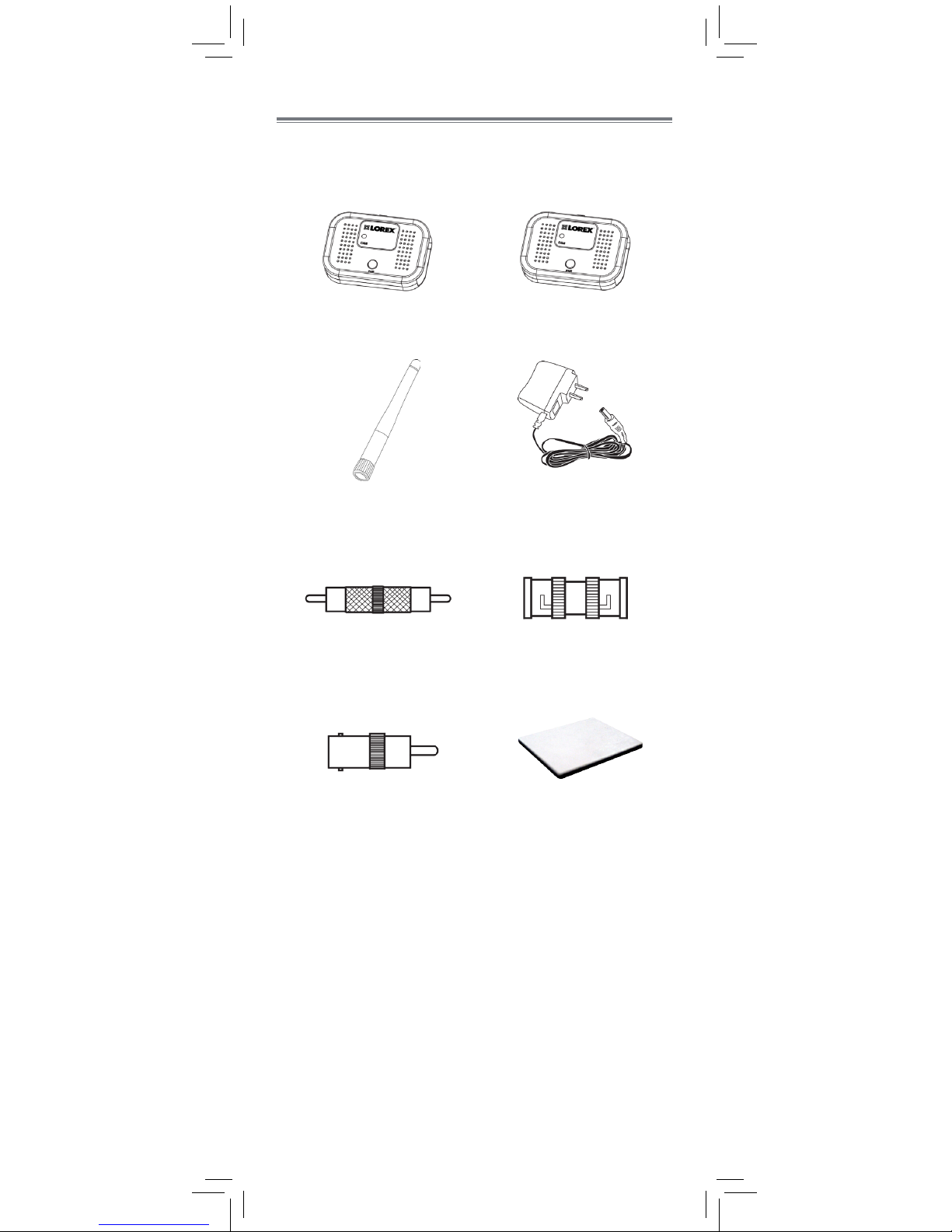
Product Includes
Removable Wireless
Antenna (SMA)
x2
Double-Sided Tape
x4
Check your package to confirm that you have received
the complete system, including all components shown
below.
Wireless Transmitter Wireless Receiver
x1 x1
RCA-to-RCA Coupler BNC-to-BNC Coupler
x1 x1
BNC-to-RCA Adapter
x1
Power Adapter
x2
Page 5

3
Wireless Receiver / Transmitter
2
1
4
3
5
Removable Wireless Antenna (SMA):
Connects to antenna jack.
1
Pairing Button:
For details, see “Pairing the Transmitter
and Receiver” on page 13.
DC Power:
Connect power adapter to power on the unit.
Termination Cable:
Includes BNC video output and RCA audio
output. An audio camera is required to use
the audio function.
Pairing Status LED:
Glows green steadily when the transmitter
and receiver are paired. Flashes on and off
slowly when pairing mode is active and flashes
rapidly if the units are out of range.
6
Antenna Jack
2
3
6
5
4
6
Page 6

4
Getting Started
Follow the steps below to prepare your digital wireless
converter for installation:
2
Attach antennas to the antenna jacks on the
receiver and transmitter.
1
Identify the transmitter and receiver.
Termination cables are labelled Connect to
Camera on the transmitter and Connect to
DVR on the receiver.
Once you have completed the steps above, determine
which of the following installation options is best suited
to your needs.
Standard Setup:
Extension Cable Setup:
Television Viewing Setup:
Your camera is connected directly to the
transmitter, and the receiver is connected directly
to the DVR.
See “Standard Setup” on page 6 for the
standard setup procedure.
An extension cable (not included) is used to
connect your camera to the transmitter, and the
receiver is connected directly to the DVR.
Use this setup if you want to install the transmitter
far away from the camera for better reception. For
example, if your camera is installed at the back of
a barn and the signal strength is better at the front
of the barn.
You can purchase extension cables from
www.lorextechnology.com.
See “Extension Cable Setup” on page 8 for
the extension cable setup procedure.
The camera is connected directly to the transmitter,
and the receiver is connected directly to a
television (not included).
See “Television Viewing Setup” on page 10 for
the television viewing setup procedure.
NOTE: Video and audio recording are not
available through television viewing setup.
Page 7

5
Page 8

6
Standard Setup
2
4
Connect one of the included power adapters from the transmitter to a local power outlet.
Connect the BNC and RCA (optional) cables from the receiver to your DVR.
1
3
The wireless receiver and transmitter are not weatherproof. Install in indoor locations only.
Live video from your camera appears on the monitor connected to your DVR*.
* The digital wireless converter only supports VGA resolution (640x480 pixels). Cameras that support larger resolutions will be compressed to VGA resolution.
5
(OPTIONAL) Use the included double-sided tape to attach the transmitter and/or receiver to a surface.
Use the included RCA-to-RCA and BNC-to-BNC couplers to connect the transmitter to your wired camera.
Use the power adapter provided with your wired camera to connect the camera to a local power outlet.
Connect a power adapter from the receiver to a local power outlet.
6
Page 9

7
* For audio cameras only
1
2
3
4
5
Page 10

8
Extension Cable Setup
3
5
Connect one of the included power adapters from the transmitter to a local power outlet.
Connect the BNC and RCA (optional) cables from the receiver to your DVR.
1
4
Live video from your camera appears on the monitor connected to your DVR*.
* The digital wireless converter only supports VGA resolution (640x480 pixels). Cameras that support larger resolutions will be compressed to VGA resolution.
6
(OPTIONAL) Use the included double-sided tape to attach the transmitter and/or receiver to a surface.
Connect your wired camera to the extension cable (not included).
Use the power adapter provided with your wired camera to connect the camera to a local power outlet.
Connect a power adapter from the receiver to a local power outlet.
7
The wireless receiver and transmitter are not weatherproof. Install in indoor locations only.
2
Connect the transmitter to the other end of the extension cable.
Page 11

9
* For audio cameras only
1
2
3
4
5
6
Page 12

10
Television Viewing Setup
The wireless receiver and transmitter are not weatherproof. Install in indoor locations only.
2
5
Connect one of the included power adapters from the transmitter to
a local power outlet.
Connect the BNC and RCA (optional) cables from the receiver to your
television. The audio input number or name should match the video
input (e.g., Video Input 1 and Audio Input 1).
1
3
Live video from your camera appears on your
television*.
6
(OPTIONAL) Use the included double-sided tape to
attach the transmitter and/or receiver to a surface.
Use the included RCA-to-RCA and BNC-to-BNC couplers to connect the
transmitter to your wired camera.
Use the power adapter provided with your wired camera to connect
the camera to a local power outlet.
Connect a power adapter from the receiver to a
local power outlet.
8
* The digital wireless converter only supports VGA resolution (640x480 pixels). Cameras that support larger resolutions will be compressed to VGA resolution.
4
Connect the included BNC-to-RCA adapter to the receiver’s BNC cable.
7
Power on your television and select the input that the
receiver is connected to.
Page 13

11
* For audio cameras only
3
4
5
6
7
2
1
Page 14

12
On-Screen Display
1
2
2
1
Signal indicator:
The signal indicator shows the strength of the
signal being received from the transmitter. The
number of bars in the signal indicator shows
the strength of the signal. One or no bars
indicates the signal is poor. Four bars indicate
a very strong signal.
Status indicator:
The message “Out of Range“ appears if
the receiver cannot communicate with the
transmitter.
ATTENTION: If the signal is low (e.g. 1 or 2 bars) adjust
the antennas or reposition the transmitter and / or receiver
to improve signal strength.
Page 15

13
Pairing the Transmitter
and Receiver
To pair the transmitter to the receiver:
2
1
Make sure that the receiver and transmitter
are both powered up and all antennas are
properly attached.
Place the transmitter and the receiver within
1ft of each other. Press and hold the PAIR
button on the receiver for 3 seconds to activate
pairing mode.
• The indicator LED will flash on and off to
indicate that pairing mode is active.
3
Press the PAIR button on the transmitter within
30 seconds of activating pairing mode. The
indicator LEDs on the receiver and transmitter
will glow steadily if pairing is successful.
The transmitter and receiver have already
been paired. If you have received a replacement
unit, OR if your transmitter and receiver are not paired
up, follow the steps below.
PAIR button
• The on-screen displays informs you that you
have 30 seconds to press the pair button on
the transmitter.
Page 16

14
Appendix A:
Technical Specifications
Frequency 2.400~2.480GHz
TX Power 16dBm
RX Sensitivity -81dBm
Maximum Wireless Range 492ft (150m)*
Resolution VGA (640x480)
Frame Rate Up to 25fps
Data Rate 4 Mbps
Spread Spectrum FHSS
Demodulation GFSK
Power Requirement 9V DC ± 5%
Power Consumption 240mA
Operating Humidity < 85% RH
Operating Temperature 14°F ~ 104°F / -10°C ~ 50°C
Environmental Rating Indoor Only
Termination 1x BNC video, 1x RCA audio
Weight 0.13lb / 0.06kg
*Based on unobstructed line of sight. Actual range will vary
based on surroundings.
Dimensions
0.6” /
15mm
3.2” / 80mm
2.2” /
55mm
Page 17

15
Appendix B:
Frequently Asked Questions
What are the differences between wired
and wireless systems?
Does a wireless system require power?
How far can wireless video and audio
be transmitted?
A wired system has a video cable that transmits
the video signal from the camera to a recording or
viewing device.
A wireless system does not use a video cable.
Instead, it wirelessly transmits the video signal to a
wireless receiver that is connected to your recording
or viewing device. Wireless systems do not require
cabling to be run between the camera and the viewing
/ recording device, which reduces installation time
and cost.
Yes. A typical wireless system requires two power
sources: one connected to the camera, and the other to
the receiver. The digital wireless converter requires a
third power source for the transmitter.
The signal range varies depending on the type of
building materials and/or objects the wireless signal
must pass through.
Cubical walls, drywall, glass, and windows generally
do not degrade wireless signal strength. Brick,
concrete floors, and walls degrade signal strength.
Trees that are in the line of sight of the wireless camera
and receiver may impact signal strength.
The signal range also depends on whether there are
competing signals using the same frequency as the
camera. For example, signals from cordless phones or
routers may affect signal strength.
Range Limiting Factors
1
Reflection Scattering Refraction Diffraction Attenuation
The signal
reflects back
The signal scatters
back into multiple
new signals
The signal bends
as it travels
through an
object (e.g.
glass window)
The signal
changes direction
as it passes
around an object
The signal
strength weakens
as it passes
through an object
1
Source: Xirrus (2010). “Wi-Fi Range Dynamics”.
Retrieved online at http://xirrus.gcsmarket.com/pdfs/
Xirrus_Wi-Fi_Range.pdf
Page 18

16
Are digital wireless signals secure?
Signal strength decreases as it passes through
different types of material. Try to position your wireless
transmitter and receiver in a location where the signal
does not pass through metal or concrete blocks, which
can significantly reduce signal strength (as shown in
the table below).
Material Signal Reduction (%)
Plaster & Wood 10 - 30%
Brick 30 - 50%
Concrete Cinder Blocks 50 - 70%
Metal & Metal Cladding 70 - 90%
NOTE: Signals that must pass through wet or moist
materials (e.g. shrubs and trees) may be significantly
reduced.
The stronger the signal strength, the higher the video
frame rate. The lower the signal strength, the lower the
video frame rate.
Yes. Lorex digital wireless products feature a wireless
transmission method called Frequency Hopping Spread
Spectrum (FHSS). This type of signal is highly resistant
to eavesdropping as it generates a channel hopping
sequence using an algorithm generated by the
receiver, which only the transmitter can follow through
the “pairing” function.
Pairing is an electronic handshake between digital
wireless devices. Digital wireless transmitters can
only be paired to one receiver. This is to prevent
interception by third parties, and prevents any other
device from picking up the signal—this also means that
you cannot pair one transmitter to multiple receivers.
How many digital wireless converters
can I install?
It is recommended to install a maximum of 4 wireless
converters per installation (4 receivers and 4
transmitters). Minimum space between receivers should
be 2ft / 0.6m to minimize potential signal strength
degradation.
Full Signal Strength Low Signal Strength
(high frame rate) (low frame rate)
Page 19

17
Appendix C: Troubleshooting
Problem Solution
There is no picture
from the camera(s)
• Make sure that your camera is
plugged into a power outlet and
that the power adapter is plugged in
properly.
• Move the transmitter closer to the
receiver.
The picture is
dropping
• Move the transmitter closer to the
receiver.
• Try repositioning the transmitter,
receiver, or both to improve the
reception.
The picture is or has
become choppy
• The picture may become choppy
when experiencing a lower frame rate
(e.g. 6 frames per second vs. a higher
20 frames per second).
• Try moving the transmitter closer to the
receiver.
• Remove obstructions between the
receiver and transmitter.
There is no audio
from the camera
• You must have an audio camera in
order to receive audio.
• Ensure your television / computer
speakers are not muted.
• Make sure the RCA audio output
cable is connected to your DVR or
television audio input.
• Make sure audio recording is enabled
on your DVR. See your DVR manual
for further instruction.
The picture appears
fuzzy
• When viewing on a large-screen TV
or monitor (especially high-definition
televisions), the picture might seem
fuzzy as the system is limited to VGA
resolution (640x480), while the TV
or monitor supports a much higher
resolution.
• For best performance, use with
TV PIP (Picture in Picture) function.
Check your TV product manual to see
if this feature is available on your TV.
Product Support is available 24/7 including product
information, user manuals, quick start up guides and
FAQ’s at www.lorextechnology.com/support.
Need Help?
Page 20

18
CLEANING
Clean the product with a slightly damp cloth or an anti-static cloth.
Never use cleaning agents or abrasive solvents.
• Do not clean any part of the product with cleaners with thinners or
other solvents and chemicals. This may cause permanent damage to
the product, which is not covered by the Warranty. When
necessary, clean it with a damp cloth.
• Keep the product away from hot, humid areas or strong sunlight,
and do not get it wet.
• Every effort has been made to ensure high standards of reliability
for your product. However, if something does go wrong, please do
not try to repair it yourself. Contact Customer Service for assistance.
DISPOSAL OF THE DEVICE
At the end of the product lifecycle, you should not
dispose of this product with normal household waste,
but take the product to a collection point for the
recycling of electrical and electronic equipment. The
symbol on the product, user’s guide, and/or box
indicates this.
Some of the product materials can be re-used if you
take them to a recycling point. By reusing some
parts or raw materials from used products you make
an important contribution to the protection of the
environment.
Please contact your local authorities in case you need more information
on the collection points in your area.
NOTICES
WARNING: Any changes or modifications not expressly approved by
the grantee of this device could void the user’s authority to operate the
device.
FCC NOTICE
This equipment has been certified and found to comply with the limits
regulated by the FCC part 15, subpart C. Operation is subject to
the following two conditions: (1) this device may not cause harmful
interference, and (2) this device must accept any interference received,
including interference that may cause undesired operation. This
equipment has been tested and found to comply with the limits for a
Class B digital device, pursuant to Part 15 of the FCC rules. These
limits are designed to provide reasonable protection against harmful
interference in a residential installation. This equipment generates, uses
and can radiate radio frequency energy and, if not installed and used
in accordance with the instructions, may cause harmful interference to
radio communications.
However, there is no guarantee that interference will not occur in a
particular installation. If this equipment does cause harmful interference
to radio or television reception (which can be determined by turning
the equipment on and off), the user is encouraged to try to correct the
interference by one or more of the following measures:
• Reorient or relocate the receiver
• Increase the separation between the equipment and receiver
• Connect the equipment into an outlet on a circuit different from that
to which the receiver is connected
• Consult the dealer or an experienced radio or television technician
for assistance
CAUTION: To maintain compliance with the FCC’s RF exposure
guidelines, place the transmitter and receiver at least 20cm (7.87in)
from nearby persons.
CANADA/IC NOTICE
This device complies with Industry Canada licence-exempt RSS
standard(s). Operation is subject to the following two conditions: (1)
this device may not cause interference, and (2) this device must accept
any interference, including interference that may cause undesired
operation of the device.
Page 21

USER’S GUIDE
LW2290B
Version 2.0
Copyright © Lorex Corporation 2014
www.lorextechnology.com
 Loading...