

Page 1

WIRELESS SECURITY CAMERA
ENGLISH
FRANÇAIS
ESPAÑOL
WITH AUDIO
USER’S GUIDE
LW2277
Version 2
.0
LW2277
Pictures of white camera in instructions are for
illustration purposes only.
Page 2

Safety Precautions
• Read this guide carefully and keep it for future
reference.
• Follow all instructions for safe use of the product and
handle with care.
• Use the camera within given temperature,
humidity, and voltage levels noted in the Technical
Specifications.
• Do not disassemble the camera.
• Do not point the camera directly towards the sun or a
source of intense light.
• For outdoor use, installation in a sheltered location is
recommended.
• Periodic cleaning may be required. Use a damp cloth
only. Do not use harsh cleaners or aerosol cleaners.
• Power supply cords should be routed so that they are
not likely to be walked on or pinched by items placed
upon or against them, paying particular attention to
cords at plugs.
• Slots and openings in the case are provided for
ventilation to ensure reliable operation of the video
product and to protect it from overheating. These
openings must not be blocked or covered.
• Do not use attachments unless recommended in the
instructions as they may cause a hazard.
• The cameras provided with this system should be
mounted to a wall or ceiling only as instructed in this
guide, using the provided mounting brackets.
• Never push objects for any kind into this video product
through openings.
• Never spill liquid of any kind on the video product.
• It is recommended to use a surge protector with this
video product.
• The wireless receiver is not weatherproof. Install the
receiver in an indoor location only.
Legal Notice Regarding Audio Recording
Audio recording without consent is illegal in certain
jurisdictions. Lorex Technology Inc. assumes no liability
for use of its products that does not conform with local
laws.
Page 3

ENGLISH
Table of Contents:
Product Includes ..............................2
Wireless Receiver ............................3
Wireless Camera .............................4
Installing the Camera ......................5
Installation Tips & Warnings ..................... 5
Mounting Positions ..................................5
To Install the Camera ............................... 6
Connecting to a DVR .......................8
Connecting to a TV ..........................9
On-Screen Display .........................10
Pairing Cameras ...........................11
Appendix A:
Technical Specifications .................12
Camera ...............................................12
Receiver ............................................... 12
Dimensions ...........................................13
Appendix B:
Frequently Asked Questions ..........14
Appendix C: Extending
Wireless Signal Range ...................17
Appendix D: Troubleshooting ........19
Need Help? ...................................19
1
Page 4
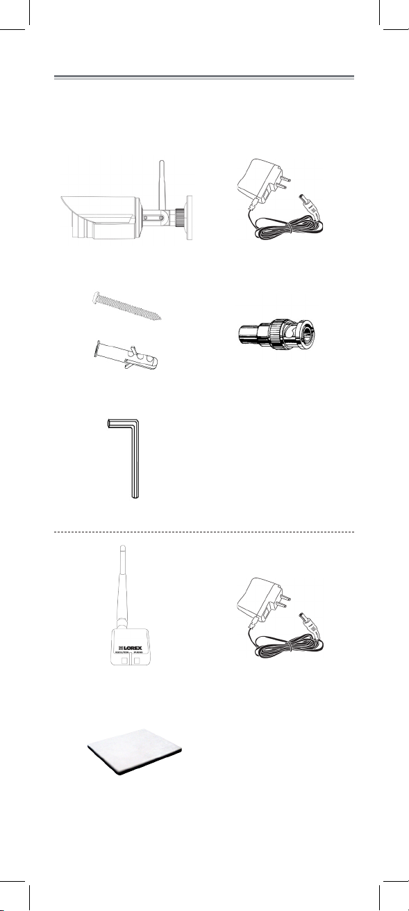
Product Includes
Check your package to confirm that you have received
the complete system, including all components shown
below.
x1*
Camera Power Adapter
x3*
x3*
Screws & Anchors
x1*
Allen Key
RCA-to-BNC Adapter
x1*
x1*
x1*
Receiver
x1*
Double-Sided Tape
* Number of cameras and receivers may vary by model.
Power Adapter
2
x1*
Page 5
ENGLISH
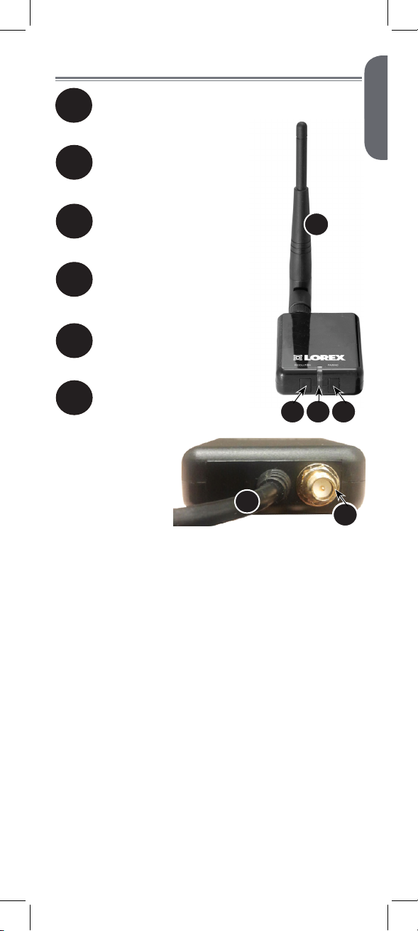
Wireless Receiver
Removable Wireless Antenna (SMA):
1
Connects to antenna jack on the
back of the receiver.
Resolution button:
2
Press to switch between VGA
and QVGA resolution1.
Front LED:
3
Glows green to indicate the
receiver is powered on.
Pairing button:
4
For details, see See “Pairing
Cameras” on page 11.
Termination cable:
5
Contains power, RCA video,
and RCA audio connectors.
Antenna jack:
6
Connection point for the
wireless antenna.
5
1
3 4
2
6
6
1. VGA mode has a resolution of 640 X 480 pixels; QVGA
mode has a resolution of 320 X 240 pixels. Use VGA mode
for best video performance. Use QVGA mode for a higher
video frame rate.
3
Page 6
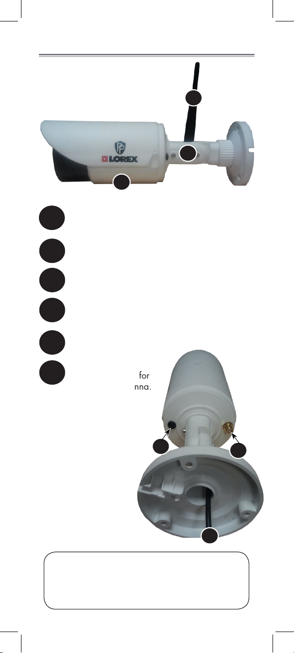
Wireless Camera
3
Removable Wireless Antenna (SMA):
1
Connects to antenna jack on the back of the
camera.
Camera stand
2
Microphone
3
Pairing button:
4
For details, See “Pairing Cameras” on page
11.
1
2
AC Power Cable
5
Antenna jack:
6
Connection point for
the wireless antenna.
4
5
ATTENTION: This camera includes an Auto Mechanical
IR Cut Filter. When the camera changes between Day/
Night viewing modes, an audible clicking noise may
be heard from the camera. This clicking is normal and
indicates that the camera filter is working.
4
6
6
Page 7
ENGLISH
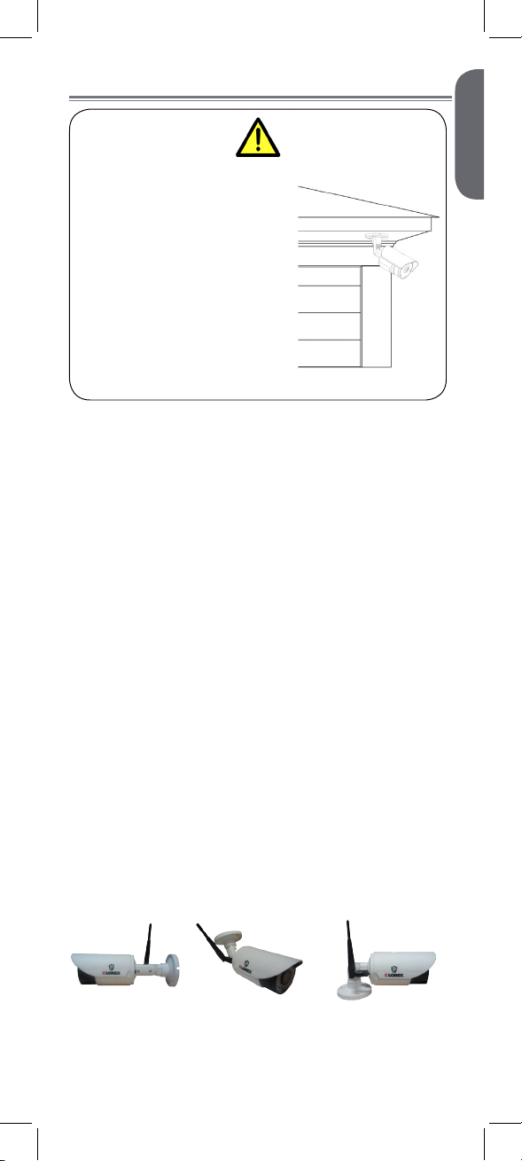
Installing the Camera
Cameras are suitable for
outdoor installation.
Installation in a sheltered
location is recommended.
For example, install under
shelter protected from the
elements, such as beneath
roof eaves. The diagram to
the right shows an example
of an ideal location for
outdoor placement.
Installation Tips & Warnings
• Aim the cameras to best optimize the viewing area:
select a location for the camera that provides a clear
view of the area you want to monitor.
• Install camera in an area that is free from dust, and
that is not in line-of-sight to a strong light source or
direct sunlight.
• Avoid installing the camera where there are thick
walls or obstructions between the camera and the
receiver.
• Avoid installing in a location which requires the
wireless signal to pass through cement, concrete,
and metal structures. This will reduce the range of
transmission. For details, s See “Appendix B:
Frequently Asked Questions” on page 14.
• Select a location for the camera that has an ambient
temperature between 14°F ~ 122°F (–10°C ~ 50°C).
• Not intended for submersion in water. For
outdoor use, installation in a sheltered location is
recommended.
Mounting Positions
You may mount your camera on a wall, ceiling, or
counter. See the images below for recommended
configurations of the camera stand and antenna.
WALL CEILING COUNTER
5
Page 8
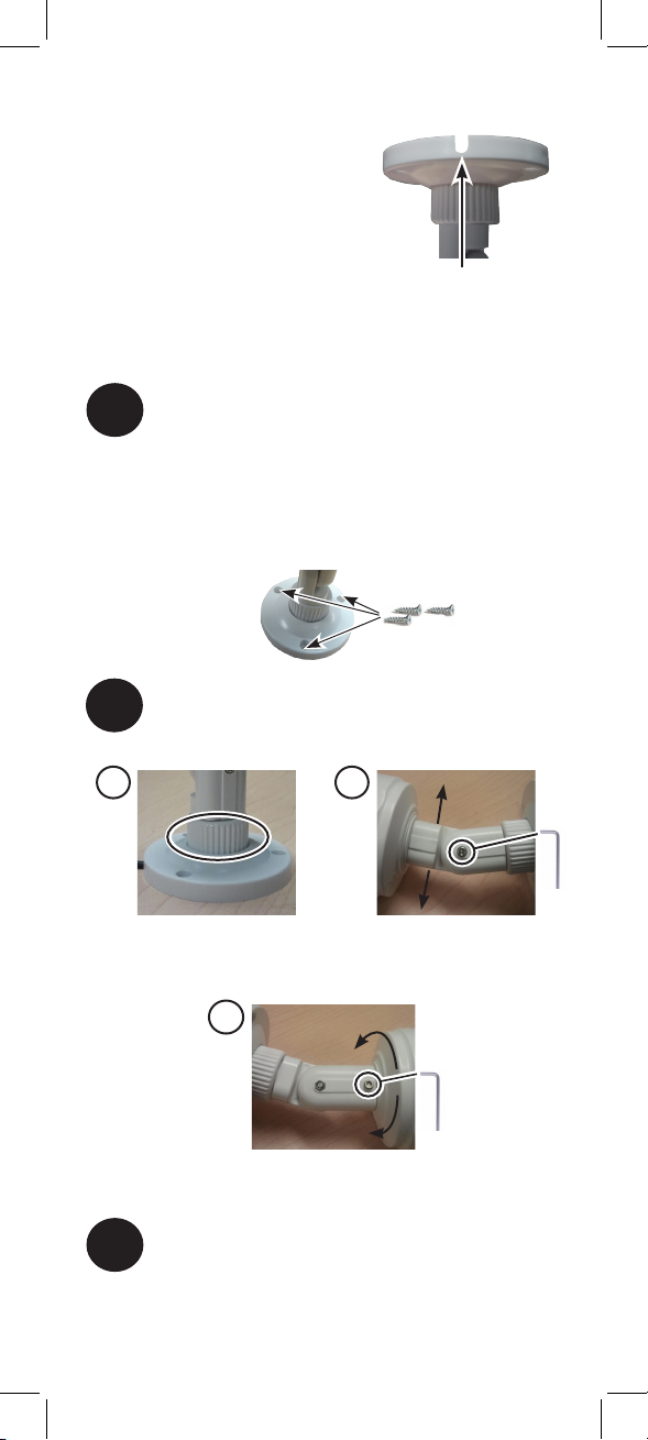
To Install the Camera
NOTE: Before you begin,
decide whether to run the
power cable through the wall /
ceiling (drilling required)
or along the wall / ceiling.
If you run the cable
along the wall / ceiling,
you must run it through the cable notch on
the base. This will keep the camera base flush to the
surface when mounted.
Use the included mounting screws to mount the
1
camera to the mounting surface:
• Mark the position of the screw holes on the wall.
• Drill holes and insert the drywall plugs (included)
as needed.
• Firmly attach the stand to the wall using the
provided screws.
Adjust the position and angle of the camera
2
until the desired view is set:
Cable Notch
A B
A) Turn the adjustment ring
to tighten / loosen the stand
connection. Adjust the camera’s
horizontal position.
C
C) Loosen upper screw with the
included Allen key to rotate the
camera housing.
Screw the antenna to the back of the camera.
3
B) Loosen lower screw with the
included Allen key to adjust the
camera’s vertical position.
6
Page 9
ENGLISH
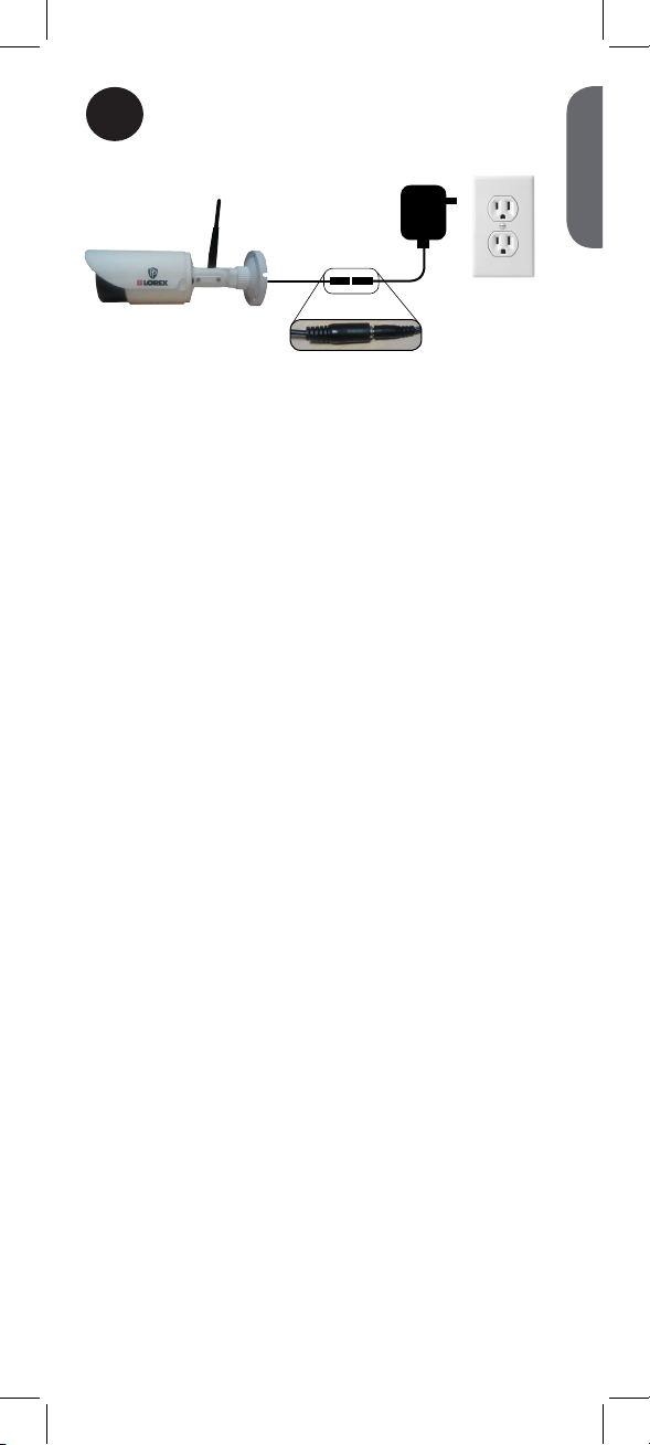
Connect the power cable from the camera to
4
the power adapter. Plug the power adapter
into a power outlet or surge protector.
7
Page 10
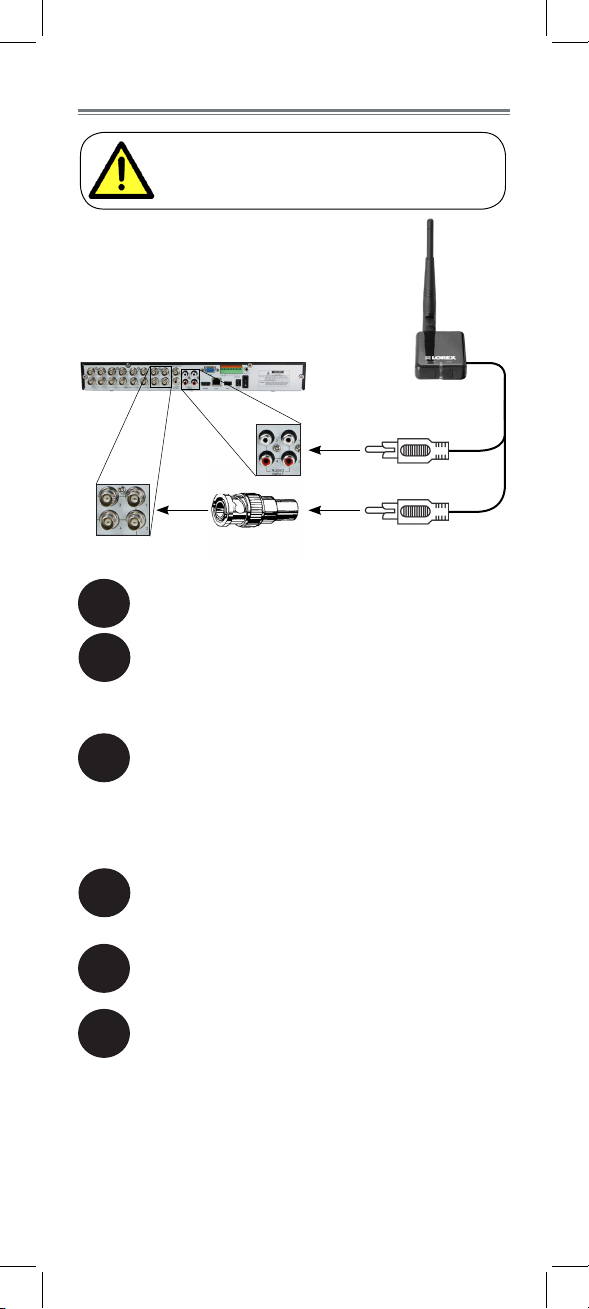
Connecting to a DVR
Before powering on the receiver, make sure
to first connect and power on the camera.
This will ensure a proper connection.
Screw the antenna to the back of the receiver.
1
Connect the RCA-to-BNC adapter (included)
2
to the yellow video cable. Connect the yellow
video cable to a BNC video input on your
recording device.
AUDIO (white)
VIDEO (yellow)
Connect the white audio input cable to an
3
audio input on your recording device.
NOTE: The audio input number or name should
match the video input where you connect the video
input (e.g. Video Input 1 and Audio Input 1).
Connect the power cable to the power
4
adapter. Plug the power adapter into a power
outlet or surge protector.
Place the receiver in a place that will have
5
clear reception to your camera1.
OPTIONAL: Use the included double-sided
6
tape to attach the wireless receiver to a flat
surface (e.g. a desk or a wall).
1. Avoid installing in a location which requires the wireless
signal to pass through cement, concrete, and metal structures.
This will reduce the range of transmission.
8
Page 11
ENGLISH
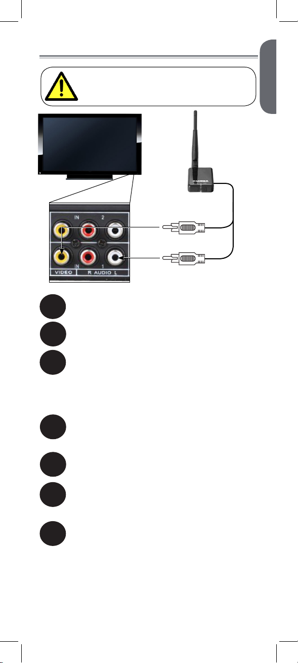
Connecting to a TV
Before powering on the receiver, make sure
to first connect and power on the camera.
This will ensure a proper connection.
AUDIO (white)
VIDEO (yellow)
Screw the antenna to the back of the receiver.
1
Connect the yellow video input cable to a
2
video input on your recording device.
Connect the white audio input cable to an
3
audio input on your recording device.
NOTE: The audio input number or name should
match the video input (e.g. Video Input 1 and Audio
Input 1).
Connect the power cable to the power
4
adapter. Plug the power adapter into a power
outlet or surge protector.
Place the receiver in a place that will have
5
clear reception to your camera1.
OPTIONAL: Use the included double-sided
6
tape to attach the wireless receiver to a flat
surface (e.g. a desk or a wall).
Power on your television and select the input
7
that the receiver is connected to.
1. Avoid installing in a location which requires the wireless
signal to pass through cement, concrete, and metal structures.
This will reduce the range of transmission.
9
Page 12
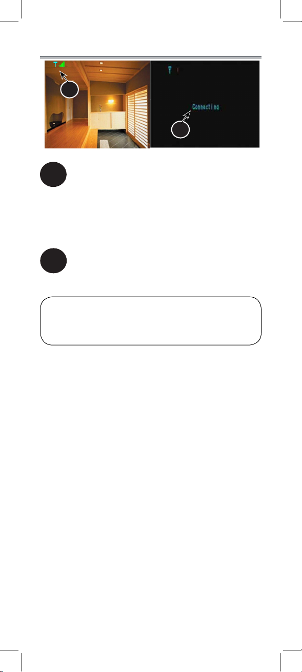
On-Screen Display
1
2
Signal indicator:
1
The signal indicator shows the strength of the
signal being received from the camera. The
number of bars in the signal indicator shows
the strength of the signal. One or no bars
indicates the signal is poor. Four bars indicate
a very strong signal.
Status indicator:
2
The message “Connecting” appears when the
receiver is trying to locate a camera.
ATTENTION: If the signal is low (e.g. 1 or 2 bars) adjust
the antennas or reposition the camera or receiver to
improve signal strength.
10
Page 13
ENGLISH
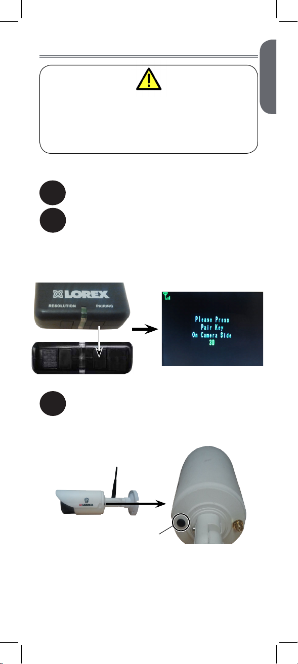
Pairing Cameras
The camera and receiver have already been
pre-paired out of the box, which means that they
are exclusively communicating with each other.
If for some reason the pairing is lost, follow these
steps to pair up the camera and receiver.
To pair the camera to the receiver:
Make sure that the camera and receiver are
1
both powered up.
On the receiver, press and hold the PAIRING
2
button for 5 seconds to activate the pairing
function.
• The on-screen displays informs you that you
have 30 seconds to press the pair button on the
camera.
Press the black pair button on the back of the
3
camera. You must press the pair button on
the camera within 30 seconds of pressing the
PAIRING button on the wireless receiver.
Pair button
If pairing is successful, live video from the camera will
immediately appear on the monitor.
11
Page 14
Appendix A:
Technical Specifications
Camera
Frequency 2.400~2.480GHz
TX Power 16dBm
AGC On
Maximum Range Up to 500ft / 150m outdoors*
Image Sensor 1/4” Color CMOS
Effective Pixels H: 640, V: 480
Lens 4.5mm F1.5
Field of View (Diagonal) 68
AES Shutter Speed 1/60 ~ 1/62,500
Night Vision Range
IR LED 18 pcs
Power Adapter 12.0V DC 500mA
Power Consumption 455mA Max with IR LED
Operating Temperature
Range
Indoor / Outdoor Both (IP66)
Weight 0.6lbs / 0.3kg
1
Up to 165ft / 50m indoors*
º
Up to 140ft (43m) / 100ft (30m)
130mA Max without IR LED
14°F ~ 122°F (–10°C ~ 50°C)
Receiver
Frequency 2.400~2.480GHz
RX Sensitivity -81dBm
Demodulation GFSK
Data Rate 160Kb/s
Supported Resolution VGA (640 x 480) up to 12 FPS
QVGA (320 x 240) up to 30 FPS
Termination 1x RCA video, 1x RCA audio
Power Adapter 12.0V DC 500mA
Power Consumption 130mA Max
Weight 0.2lbs / 0.1kg
*Based on unobstructed line of sight. Actual range will vary
based on surroundings.
1. Stated IR illumination range is based on ideal conditions
in typical outdoor night time ambient lighting and in total
darkness. Actual range and image clarity depends on
installation location, viewing area and light reflection /
absorption level of object.
2. Frames Per Second.
12
2
Page 15
ENGLISH
Dimensions
5.3” /
135mm
8.9” / 225mm
2.8” / 71mm
2.9” /
74mm
2.3” /
57mm
4.5” /
114mm
1.8” /
44mm
13
Page 16
Appendix B:
Frequently Asked Questions
What are the differences between wired
and wireless cameras?
A wired camera has a video cable that transmits
the video signal from the camera to a recording or
viewing device.
A wireless camera does not use a video cable.
Instead, it wirelessly transmits the video signal to a
wireless receiver that is connected to your recording
or viewing device. Although the typical digital wireless
camera is priced slightly higher than a wired camera,
wireless cameras can provide cost savings compared
to standard wired setups. For example, wireless
cameras do not require cabling to be run between the
camera and the viewing / recording device, which
reduces installation time and cost.
Does a wireless camera require power?
Yes. Wireless cameras require two power sources: one
connected to the camera, and the other to the receiver.
How far can a wireless camera transmit
a video signal?
In an open field (with line of sight), a typical wireless
camera has a range between 250 to 500ft. In a
closed environment—such as an interior of a house—
the wireless camera range is between 100 to 165ft
The signal range varies depending on the type of
building materials and/or objects the wireless signal
must pass through.
Cubical walls, drywall, glass, and windows generally
do not degrade wireless signal strength. Brick,
concrete floors, and walls degrade signal strength.
Trees that are in the line of sight of the wireless camera
and receiver may impact signal strength.
The signal range also depends on whether there are
competing signals using the same frequency as the
camera. For example, signals from cordless phones or
routers may affect signal strength.
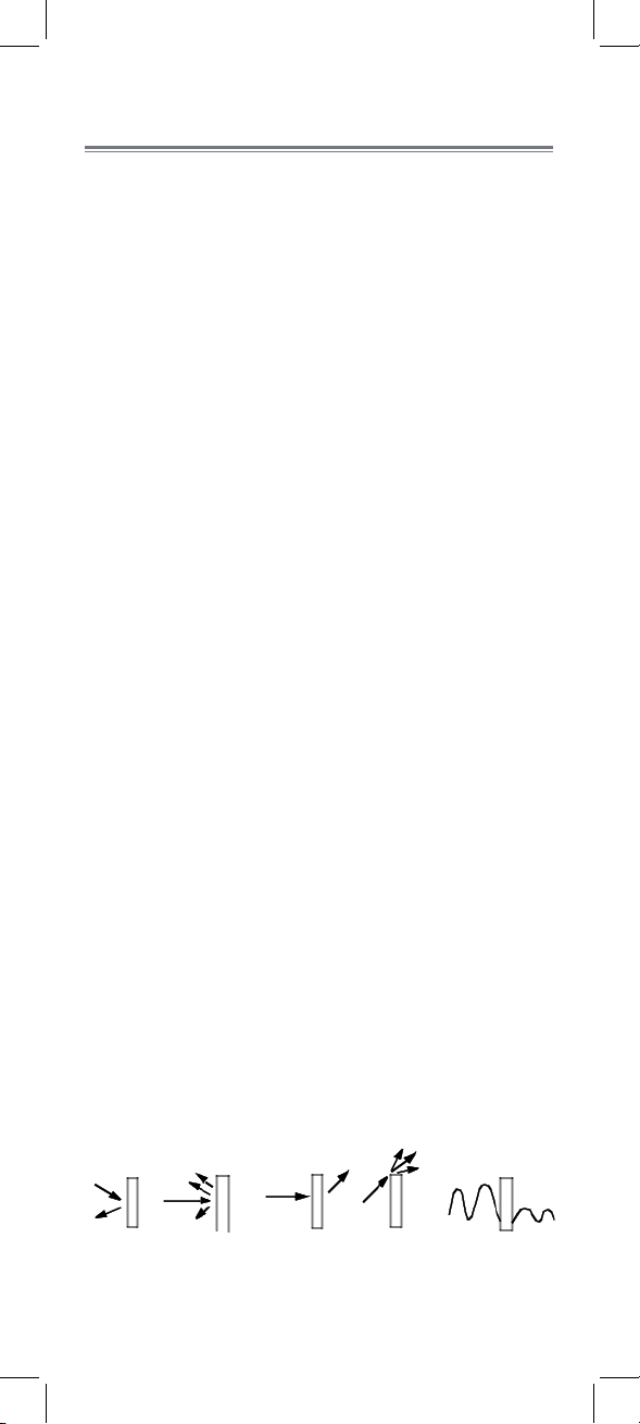
Range Limiting Factors
Reflection Scattering Refraction Diffraction Attenuation
The signal
reflects back
The signal scatters
back into multiple
new signals
1
The signal bends
as it travels
through an
object (e.g.
glass window)
14
The signal
changes direction
as it passes
around an object
1
Source: Xirrus (2010). “Wi-Fi Range Dynamics”.
Retrieved online at http://xirrus.gcsmarket.com/pdfs/
Xirrus_Wi-Fi_Range.pdf
The signal
strength weakens
as it passes
through an object
Page 17
ENGLISH
Signal strength decreases as it passes through different
types of material. Try to position your wireless camera
and receiver in a location where the signal does not
pass through metal or concrete blocks, which can
significantly reduce signal strength (as shown in the
table below).
Material Signal Reduction (%)
Plaster & Wood 10 - 30%
Brick 30 - 50%
Concrete Cinder Blocks 50 - 70%
Metal & Metal Cladding 70 - 90%
NOTE: Signals that must pass through wet or moist
materials (e.g. shrubs and trees) may be significantly
reduced.
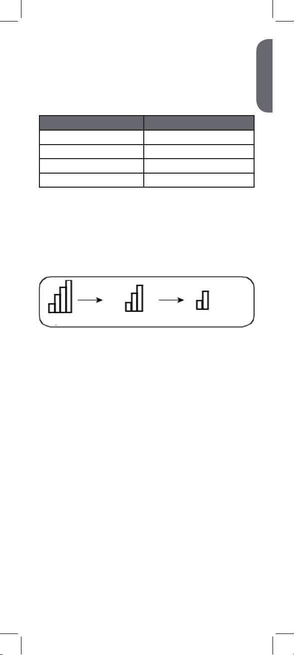
The stronger the signal strength, the higher the video
frame rate. The lower the signal strength, the lower the
video frame rate.
Full Signal Strength Low Signal Strength
(high frame rate) (low frame rate)
Are digital wireless camera signals secure?
Yes. Lorex digital wireless products feature a wireless
transmission method called Frequency Hopping
Spread Spectrum (FHSS). This type of signal is highly
resistant to eavesdropping as it generates a channel
hopping sequence using an algorithm generated by
the receiver, which only the camera can follow through
the “pairing” function.
Pairing is an electronic handshake between digital
wireless devices. Digital wireless cameras can only be
paired to one receiver. This is to prevent interception
by third parties, and prevents any other device from
picking up the signal—this also means that you cannot
pair one camera to multiple receivers.
How many wireless cameras can I
install?
It is recommended to install a maximum of 4 wireless
cameras per system (4 receivers and 4 cameras).
Minimum space between receivers should be
2ft / 0.6m and minimum space between cameras
should be 6.5ft / 2m to minimize potential signal
strength degradation.
15
Page 18

How many frames per second should I
expect from a digital wireless camera?
Current Lorex digital wireless cameras offer 10 - 30
FPS (Frames Per Second) performance. Actual frame
rate depends mainly on signal strength (see the chart
in section above).
For details on supported resolutions and frame rates
for this model, s See “Appendix A:
Technical Specifications” on page 12.
16
Page 19
ENGLISH
Appendix C: Extending
Wireless Signal Range
DISCLAIMER: Certain accessories
are not available in all markets.
There are several ways to boost your wireless signal
as well as options to help you extend the range of the
wireless signal.
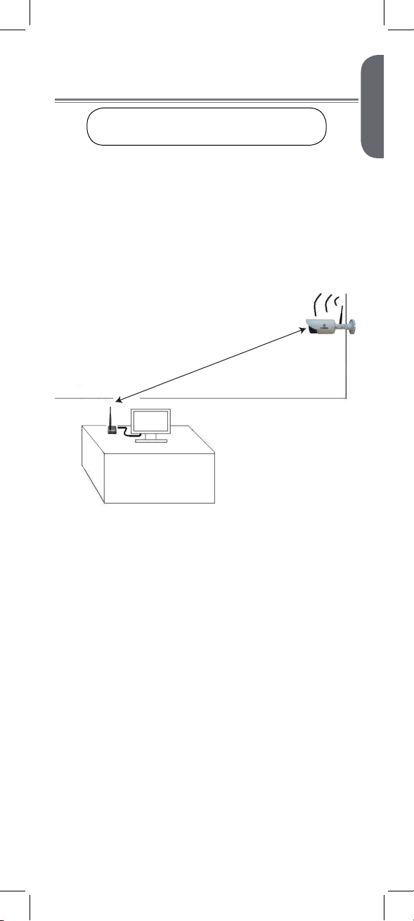
Clear Line-of-Sight
The digital wireless signal is virtually interference free.
However, you should always ensure there is a clear
line-of-sight between the camera and the receiver.
Clear line-of-sight
Receiver
Obstacles
There should be little to no obstacles obstructing the
line-of-sight between the camera and the receiver. Solid
objects, such as concrete and metal, may limit the
range of the wireless signal.
Extending Your Wireless Signal
Even with a clear line-of-sight between your camera(s)
and your receiver, you may experience a lower video
frame rate simply due to the distance between your
wireless devices.
Accessory antennas are available that can help extend
the range of your wireless signal.
17
Page 20
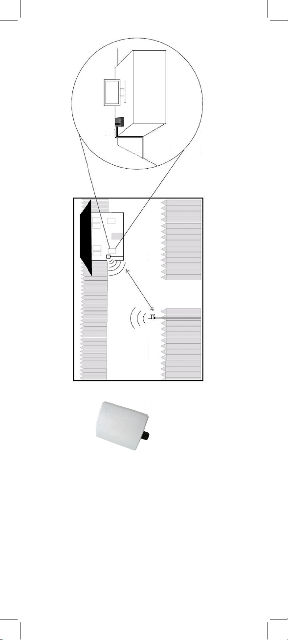
Wireless receiver
Directional Panel
Antenna
Indoor installation
Clear line-of-sight
Wireless Camera
Outdoor installation
2.4 GHz Directional Wireless
Panel Antenna
Use the 2.4GHz Directional
Wireless Panel Antenna (model #:
ACCANTD9) to focus a wireless
signal onto the camera in order to
18
increase range of transmission (clear
line-of-sight between the camera and
the antenna is required). A 20ft extension cable is
included help with proper position of the antenna.
Visit www.lorextechnology.com for more
details on wireless antennas and accessories.
Page 21
ENGLISH
Appendix D: Troubleshooting
Problem Solution
There is no picture
from the camera(s).
The picture is
dropping.
The picture is or has
become choppy.
There is no audio
from the camera.
The picture is white. • “Washout” or “white wash” can occur
The picture appears
fuzzy.
The picture is
pixelated.
• Make sure that the camera is plugged
into a power outlet and that the power
adapter is plugged in properly.
• Move the camera closer to the
receiver.
• Move the camera closer to the
receiver.
• Try repositioning the camera, receiver,
or both to improve the reception.
• The picture may become choppy
when experiencing a lower frame rate
(e.g. 6 frames per second vs. a higher
20 frames per second).
• Try moving the camera closer to the
receiver.
• Remove obstructions between the
receiver and camera.
• Try switching to QVGA mode by
pressing the RESOLUTION button
on the receiver. Resolution will be
reduced, but video frame rate will
increase.
• Make sure the RCA audio output
cable is connected to your DVR or
television audio input.
• Make sure audio recording is enabled
on your DVR. See your DVR manual
for further instruction.
when a strong light source is pointed
at the camera lens. The camera lens is
not harmed during a white wash.
• Do not point your camera towards a
bright light source.
• When viewing on a large-screen TV
or monitor (especially high-definition
televisions), the picture might seem
fuzzy as the camera is limited to VGA
resolution (640x480 pixels), while the
TV or monitor supports a much higher
resolution.
• For best performance, use with
TV PIP (Picture in Picture) function.
Check your TV product manual to see
if this feature is available on your TV.
• You may be in QVGA mode. Try
switching to VGA mode by pressing
the RESOLUTION button on the
receiver.
Need Help?
Product Support is available 24/7 including product
information, user manuals, quick start up guides and
FAQ’s at www.lorextechnology.com/support.
19
Page 22

CLEANING
Clean the monitor and camera with a slightly damp cloth or an antistatic cloth. Never use cleaning agents or abrasive solvents.
• Do not clean any part of the product with cleaners with thinners or
other solvents and chemicals. This may cause permanent damage to
the product, which is not covered by the Warranty. When
necessary, clean it with a damp cloth.
• Keep your camera and monitor away from hot, humid areas or
strong sunlight, and do not get it wet.
• Every effort has been made to ensure high standards of reliability
for your baby monitor. However, if something does go wrong,
please do not try to repair it yourself. Contact Customer Service for
assistance.
DISPOSAL OF THE DEVICE
At the end of the product lifecycle, you should not
dispose of this product with normal household waste,
but take the product to a collection point for the
recycling of electrical and electronic equipment. The
symbol on the product, user’s guide, and/or box
indicates this.
Some of the product materials can be re-used if you
take them to a recycling point. By reusing some parts
or raw materials from used products you make an
important contribution to the protection of the environment.
Please contact your local authorities in case you need more information
on the collection points in your area. Dispose of the battery pack in an
environmentally-friendly manner according to your local regulations.
NOTICES
WARNING: Any changes or modifications not expressly approved by
the grantee of this device could void the user’s authority to operate the
device.
FCC NOTICE
This equipment has been certified and found to comply with the limits
regulated by the FCC part 15, subpart C. Operation is subject to
the following two conditions: (1) this device may not cause harmful
interference, and (2) this device must accept any interference received,
including interference that may cause undesired operation. This
equipment has been tested and found to comply with the limits for a
Class B digital device, pursuant to Part 15 of the FCC rules. These
limits are designed to provide reasonable protection against harmful
interference in a residential installation. This equipment generates, uses
and can radiate radio frequency energy and, if not installed and used
in accordance with the instructions, may cause harmful interference to
radio communications.
However, there is no guarantee that interference will not occur in a
particular installation. If this equipment does cause harmful interference
to radio or television reception (which can be determined by turning
the equipment on and off), the user is encouraged to try to correct the
interference by one or more of the following measures:
• Reorient or relocate the receiving antenna
• Increase the separation between the equipment and receiver
• Connect the equipment into an outlet on a circuit different from that
to which the receiver is connected
• Consult the dealer or an experienced radio or television technician
for assistance
CAUTION: To maintain compliance with the FCC’s RF exposure
guidelines, place the camera at least 20cm (7.87in) from nearby
persons.
CANADA/IC NOTICE
This device complies with Industry Canada licence-exempt RSS
standard(s). Operation is subject to the following two conditions: (1)
this device may not cause interference, and (2) this device must accept
any interference, including interference that may cause undesired
operation of the device.
20
Page 23

CAMÉRA DE SÉCURITÉ SANS FIL
ENGLISH
FRANÇAIS
ESPAÑOL
AVEC AUDIO
GUIDE DE L'UTILISATEUR
LW2277
Version 2.0
LW2277
Les images de la caméra blanche fournies dans les
instructions servent à titre d’illustration seulement.
Page 24

Mesures de sécurité
• Lire attentivement ce guide et le garder pour une
consultation ultérieure.
• Suivre les directives d'utilisation sécuritaire du produit
et le manipuler avec soin.
• Utiliser la caméra conformément à la température, à
l'humidité ainsi qu'à la tension recommandée selon les
caractéristiques techniques.
• Ne pas démonter la caméra.
• Ne pas pointer la caméra vers le soleil ou toute autre
source de lumière intense.
• Pour une utilisation à l'extérieur, il est conseillé de
l'installer dans un endroit abrité.
• Un nettoyage périodique est exigé. Utiliser un
linge humide seulement. Ne pas utiliser de produits
nettoyants forts ou en aérosols.
• Les cordons d'alimentation doivent être dirigés de
façon à ce qu'ils ne soient pas piétinés ou pincés
par des articles situés près de ceux-ci ou appuyés
dessus; porter une attention particulière aux cordons
d'alimentation et aux fiches.
• Les fentes et ouvertures du boitier sont nécessaires à
la ventilation afin d'assurer le bon fonctionnement du
produit et de le protéger contre les surchauffes. Ces
ouvertures ne doivent pas être obstruées ou couvertes.
• Ne pas utiliser d'accessoires sauf si cela est
recommandé dans les directives puisqu'ils pourraient
constituer un danger.
• Les caméras fournies avec ce système doivent être
montés sur un mur ou au plafond à l'aide des supports
de fixations et conformément aux directives de ce
guide.
• Ne jamais insérer d'objets dans les ouvertures de ce
produit.
• Ne jamais renverser de liquide sur le produit.
• Il est recommandé d'utiliser un limiteur de surtension
avec ce produit.
• Le récepteur sans fil n'est pas à l'épreuve des
intempéries. Installer le récepteur à l'intérieur
seulement.
Avis juridique concernant
l'enregistrement audio
L'enregistrement audio sans consentement est illégal
dans certains territoires. Lorex technology inc. n'assume
aucune responsabilité pour l'utilisation non conforme
aux lois locales de ses produits.
Page 25

FRANÇAIS
Table des matières :
Le produit comprend .......................2
Récepteur sans fil ............................3
Caméra sans fil ...............................4
Installation de la caméra .................5
Astuces d'installation et
avertissements ......................................... 5
Positions de montage ............................... 5
Pour installer la caméra ............................6
Branchement à un DVR ...................8
Branchement à une télévision ..........9
Affichage sur écran .......................10
Jumelage des caméras ..................11
Annexe A :
Spécifications techniques ...............12
Caméra ...............................................12
Récepteur ............................................. 12
Dimensions ...........................................13
Annexe B :
Foire aux questions .......................14
Annexe C : Amélioré
la portée du signal sans fil ............17
Annexe D : Dépannage .................19
Besoin d'aide? ..............................19
1
Page 26

Le produit comprend
Vérifier votre emballage pour vous assurer que vous
avez reçu le système complet, y compris tous les
composants illustrés ci-dessous.
x1*
Caméra Bloc d'alimentation
x3*
x3*
Vis et ancrages
x1*
Clé Allen
Adaptateur RCA vers BNC
x1*
x1*
x1*
Récepteur
x1*
Ruban double-face
* Le nombre de caméras et de récepteur peut varier selon le
modèle.
Bloc d'alimentation
2
x1*
Page 27

FRANÇAIS
Récepteur sans fil
Antenne amovible sans fil (SMA) :
1
Se connecte à la prise d'antenne
située à l'arrière du récepteur.
Bouton de résolution :
2
Appuyer sur celui-ci pour passer
du mode de résolution VGA
au mode de résolution QVGA1.
DEL avant :
3
Le voyantvert est allumé pour
indiquer que le récepteur est
allumé.
Bouton de jumelage :
4
Pour de plus amples
renseignements, se référer à la
section « Jumelage des
caméras » à la page 11
Extrémité de câble :
5
Comprends l'alimentation, la
vidéo RCA ainsi que les
connecteurs audio RCA.
Prise d'antenne :
6
Point de branchement pour
l'antenne sans fil.
1
3 4
2
5
6
6
1. La résolution du mode VGA est de 640 X 480 pixels; le
mode QVGA est de 320 X 240 pixels. Utiliser le mode VGA
pour des performances vidéo optimales. Utiliser le mode
QVGA pour une meilleure séquence d'images.
3
Page 28

Caméra sans fil
3
Antenne amovible sans fil (SMA) :
1
Se connecte à la prise d'antenne située à
l'arrière du récepteur.
Support de la caméra
2
Microphone
3
Bouton de jumelage :
4
Pour de plus amples renseignements, se référer à
la section « Jumelage des caméras »
à la page 11.
Câble d'alimentation c.a.
5
1
2
Prise d'antenne :
6
Point de branchement
pour l'antenne sans fil.
4
5
ATTENTION : Cet appareil comprend un filtre IR
mécanique autonome. La caméra bascule du mode de
visionnement diurne au mode nocturne, un bruit de clic,
provenant de la caméra, peut être entendu. Ce clic est
normal et indique que le filtre de la caméra fonctionne.
4
6
6
Page 29

FRANÇAIS
Installation de la caméra
Les caméras peuvent être
installées à l'extérieur, Il est
conseillé de l'installer dans un
endroit abrité. Par exemple,
installer la caméra dans un
endroit abrité, protégé contre
les intempéries, par exemple
sous l'avant-toit de la toiture.
Le schéma ci-dessous présente
un emplacement idéal pour
une installation extérieure.
Astuces d'installation et
avertissements
• Pointer les caméras afin de maximiser l'affichage de
la zone : choisir un emplacement qui fournit une vue
claire de la zone à surveiller.
• Installer la caméra à un endroit exempt de poussière
et à l'abri d'une source de lumière ou du soleil.
• Éviter d'installer la caméra à proximité de murs épais
ou à un endroit où il y a un obstacle entre la caméra
et le récepteur.
• Éviter d'installer la caméra dans un endroit qui
nécessite que le signal sans fil passe à travers
le ciment, le béton et les structures métalliques.
Cela réduira la portée de transmission. Pour plus
d'information, se référer à la section
• Sélectionner un emplacement dont la température
ambiante se situe entre -10° C et 50° C (14° F et
122° F) pour installer la caméra.
• Ne pas submerger. Pour une utilisation à l'extérieur,
il est conseillé de faire l'installation dans un endroit
abrité. Se référer l'«Annexe B :
Foire aux questions » à la page 14.
Positions de montage
Vous pouvez monter votre caméra sur un mur, un
plafond ou un comptoir. Se référer aux images
ci-dessous pour connaitre les recommandations
concernant la configuration du support de la caméra et
de l’antenne.
MUR PLAFOND COMPTOIR
5
Page 30

Pour installer la caméra
REMARQUE : Avant de
commencer, décider s'il faut
passer les câbles à l'intérieur du
mur, dans le plafond (perçage
requis) ou le long du mur ou du
plafond. Si vous passez les
câbles le long du mur ou
du plafond, vous devez passer le câble par
l'encoche du support. Cela gardera la caméra à
niveau sur la surface lorsqu'elle est montée.
Utiliser les vis de montage (incluses) pour fixer
1
les caméras sur la surface de montage :
• Marquer la position des trous de vis sur le mur.
• Percer les trous et insérer les chevilles à cloison
sèche (inclus) si nécessaire.
• Attacher solidement le support au mur à l'aide
des vis fournies.
Ajuster l'angle de la caméra jusqu'à la
2
position souhaitée :
Encoche pour câble
A B
A) Pivoter l'anneau d'ajustement
afin de resserrer ou desserrer
l'attache au support. Ajuster la
position horizontale de la caméra.
C
C) Déserrer les vis supérieures
à l'aide d'une clé Allen afin
de faire pivoter le boitier de la
caméra.
Visser l'antenne à l'arrière de la caméra.
3
B) Desserrer les vis inférieures
à l'aide d'une clé Allen afin
d'ajuster la position verticale de
la caméra.
6
Page 31

FRANÇAIS
Brancher le câble d’alimentation de la caméra
4
au bloc d'alimentation. Brancher le bloc
d'alimentation à une prise électrique ou à un
limiteur de surtension.
7
Page 32

Branchement à un DVR
Avant de mettre le récepteur sous tension,
vérifier d'abord que la caméra est
connectée et allumée. Cela assurera une
bonne connexion.
AUDIO (blanc)
VIDÉO (jaune)
Visser l'antenne à l'arrière du récepteur.
1
Brancher l'adaptateur RCA vers BNC (inclus)
2
au câble vidéo de couleur jaune. Brancher le
câble vidéo de couleur jaune à l'entrée vidéo
BNC de votre dispositif enregistreur.
Brancher le câble audio de couleur blanc à
3
l'entrée audio de votre dispositif enregistreur.
REMARQUE : Le numéro ou le nom de l'entrée
audio doit correspondre à l'entrée vidéo de
branchement du câble BNC (par exemple : l'entrée
vidéo 1 et l'entrée audio 1).
Brancher le câble d’alimentation au bloc
4
d'alimentation. Brancher le bloc d'alimentation
à une prise électrique ou à un limiteur de
surtension.
Placer le récepteur dans un endroit qui
5
permettra une réception adéquate de la
caméra 1.
OPTIONNEL : Utiliser le ruban double-face
6
inclus pour fixer le récepteur sans fil sur une
surface plane (par exemple : un bureau ou un
mur).
1. Éviter d'installer la caméra dans un endroit exigeant
que le signal sans fil passe à travers à travers le ciment, le
béton et les structures métalliques. Cela réduira la portée de
transmission.
8
Page 33

FRANÇAIS
Branchement à une télévision
Avant de mettre le récepteur sous tension,
vérifier d'abord que la caméra est
connectée et allumée. Cela assurera une
bonne connexion.
Audio (blanc)
VIDÉO (jaune)
Visser l'antenne à l'arrière du récepteur.
1
Brancher le câble vidéo de couleur jaune à
2
l'entrée vidéo de votre dispositif enregistreur.
Brancher le câble audio de couleur blanc à
3
l'entrée audio de votre dispositif enregistreur.
REMARQUE : Le numéro ou le nom de l'entrée
audio doit correspondre à l'entrée vidéo (par
exemple : l'entrée vidéo 1 et l'entrée audio 1).
Brancher le câble d’alimentation au bloc
4
d'alimentation. Brancher le bloc d'alimentation
à une prise électrique ou à un limiteur de
surtension.
Placer le récepteur dans un endroit qui
5
permettra une réception adéquate de la
caméra 1.
OPTIONNEL : Utiliser le ruban double-face
6
inclus pour fixer le récepteur sans fil sur une
surface plane (par exemple : un bureau ou un
mur).
Allumer votre téléviseur et choisir l'entrée sur
7
lequel votre récepteur est branché.
1. Éviter d'installer la caméra dans un endroit exigeant
que le signal sans fil passe à travers à travers le ciment, le
béton et les structures métalliques. Cela réduira la portée de
transmission.
9
Page 34

Affichage sur écran
1
2
L'indicateur de signal :
1
Affiche la force du signal en cours de réception
depuis la caméra. Le nombre de barres sur
l'indicateur de signal indique l'intensité de
celui-ci. L'absence de barres ou la présence
d'une barre indique que le signal est faible.
La présence de quatre barres indique que le
signal est élevé.
Indicateur d'état :
2
Le message « Connexion » apparait lorsque le
récepteur essaie de localiser la caméra.
ATTENTION : Si le signal est faible (par exemple : 1 ou
2 barres), régler les antennes ou repositionner la caméra
ou le récepteur afin d'améliorer la puissance du signal.
10
Page 35

FRANÇAIS
Jumelage des caméras
La caméra et le récepteur sont jumelés à l'avance
afin de fonctionner dès l'installation ce qui signifie
qu’ils communiquent exclusivement entre eux. Si
pour une raison quelconque, le jumelage est perdu,
suivre les étapes suivantes pour jumeler la caméra
et le récepteur.
Pour jumeler la caméra avec le
récepteur :
S'assurer que la caméra et le récepteur sont
1
allumés.
Sur le récepteur, appuyer et maintenir le
2
bouton de JUMELAGE pendant 5 secondes
pour activer la fonction.
• Un message s'affiche à l'écran vous informant
que vous avez 30 secondes pour appuyer sur le
bouton de jumelage situé sur la caméra.
Appuyer sur le bouton de JUMELAGE de
3
couleur noir situé à l'arrière de la caméra.
Appuyer sur le bouton de jumelage situé à
l'arrière de la caméra dans les 30 secondes
suivant l'activation du bouton de JUMELAGE
du récepteur sans fil.
Bouton de
jumelage
Si le jumelage est effectué avec succès, une vidéo en
direct de la caméra apparait sur le moniteur.
11
Page 36

Annexe A :
Spécifications techniques
Caméra
Fréquence 2 400 GHz à 2 480 GHz
Puissance de transmission 16 dBm
AGC On
Portée maximale Jusqu'à 150 m (500 pi) à
Capteur d'images CMOS couleur 0,63 cm (1/5 po)
Pixels effectifs H : 640, V : 480
Objectif
Champ de Vision (diagonal) 68
Vitesse d'obturateur AES 1/60 à 1/62,500
Portée en vision nocturne 1Jusqu'à 43 m (140 pi) ou 30 m
DEL IR 18 mcx
Bloc d'alimentation 12 V DC 500mA
Consommation 455 mA max sans DEL IR
Plage de température de
fonctionnement
Intérieur et extérieur Les deux (IP66)
Poids 0,6 lb (0,3 kg)
l'extérieur* ou jusqu'à 50 m
(165 pi) à l'intérieur*
4,5 mm F2.5
º
(100 pi)
130 mA max sans DEL IR
-10 °C à 50 °C (14 °F à 122 °F)
Récepteur
Fréquence 2 400 GHz à 2 480 GHz
Sensibilité de réception -81 dBm
Démodulation GFSK
Débit binaire 160 Kbps
Résolution prise en charge VGA (640 x 480) jusqu'à 12 FPS
QVGA (320 x 240) jusqu'à
30 FPS
Connecteur 1x RCA vidéo, 1x RCA audio
Bloc d'alimentation 12 V DC 500mA
Consommation 130 mA max
Poids 0,2 lb (0,1 kg)
*Basé sur une ligne de visée non obstruée. La portée réelle
varie en fonction de l'environnement.
1. La portée IR est indiquée pour des conditions idéales
dans une luminosité ambiante de nuit extérieure typique et
de noirceur totale. La portée actuelle et la clarté de l'image
dépendent de l'emplacement de l'installation, de la zone
surveillée et du degré de réflexion ou d'absorption de la
lumière par l'objet.
2. Images par seconde.
12
2
Page 37

FRANÇAIS
Dimensions
135 mm
(5,3 po)
225 mm
(8,9 po)
71 mm (2,8 po)
74 mm
(2,9 po)
57 mm
(2,3 po)
114 mm
(4,5 po)
44 mm
(1,8 po)
13
Page 38

Annexe B :
Foire aux questions
Quelles sont les différences entre les
caméras sans fil et avec fil?
Une caméra avec fil est munie d'un câble vidéo qui
émet le signal à partir de la caméra vers un appareil
d'enregistrement.
Une caméra sans fil n'utilise pas de câble vidéo.
Au lieu, elle transmet le signal vidéo à un récepteur
sans fil connecté à votre dispositif enregistreur ou de
visionnement. Bien que la caméra numérique sans fil
soit un peu plus dispendieuse que les caméras munies
de fil, les caméras sans fil permettent d'économiser
comparativement aux caméras standards. Par
exemple, les caméras sans fil n'ont pas besoin
d'un câble pour relier la caméra et le dispositif
d'enregistrement ou de visionnement, ce qui permet de
réduire le temps et le coût de l'installation.
Une caméra sans fil nécessite-t-elle une
alimentation électrique?
Oui. Les caméras sans fil nécessitent deux sources
d’alimentation électrique : la caméra et le récepteur
doivent être branchés.
À quelle distance une caméra sans fil
peut-elle transmettre un signal vidéo?
En plein champ (avec une visibilité directe), une
caméra sans fil type a une portée comprise entre
76,2 m et 152,40 m (250 et 500 pieds). Dans un
environnement fermé, comme à l'intérieur d'une
maison, la portée est comprise entre 30,48 m et
50,29 m (100 et 165 pieds). La portée du signal varie
selon le type de matériaux utilisés dans la construction
du bâtiment et les objets par lesquels le signal doit
passé.
Les cubicules, les cloisons sèches, le verre et les
fenêtres ne réduisent généralement pas l'intensité
du signal. La brique, les planchers de béton et les
murs réduisent l'intensité du signal. Les arbres qui
sont directement dans la ligne de visée de la caméra
sans file et du récepteur peuvent réduire l'intensité du
signal.
La portée du signal peut aussi être affectée si un
autre signal utilise la même fréquence que la caméra.
Par exemple, les signaux provenant de téléphones
ou routeurs sans fil peuvent affecter la puissance du
signal.
14
Page 39

FRANÇAIS
Facteurs de limitation de portée
Réflexion Diffusion Réfraction Diffraction Atténuation
Le signal est
réfléchi.
Le signal se divise
en plusieurs
nouveaux signaux.
Le signal se plie
lorsqu’il passe à
travers un objet
(par exemple
une vitre).
1
La puissance du
signal change de
direction lorsqu’il
passe autour d’un
objet.
1
Source : Xirrus (2010). « Wi-Fi Range Dynamics ».
Téléchargé en ligne à l'adresse http://xirrus.gcsmarket.
com/pdfs/Xirrus_Wi-Fi_Range.pdf
Lorsqu’il traverse
un objet,
l'intensité du
signal s'affaiblit.
La puissance du signal diminue lorsqu’il traverse
différents types de matériaux. Essayer de positionner
votre caméra sans fil et le récepteur dans un endroit où
le signal ne passe pas à travers des blocs métalliques
ou de béton, ce qui peut réduire considérablement
l'intensité du signal (comme indiqué dans le tableau
ci-dessous).
Matériaux Réduction de signaux (%)
Plâtre et bois
Brique 10 à 50 %
Aggloméré en béton de
mâchefer
Métal et revêtement métallique 70 à 90 %
10 à 30 %
50 à 70 %
REMARQUE : Les signaux devant traverser des
matériaux mouillés ou humides (par exemple
les arbustes et les arbres) peuvent être diminués
significativement.
Plus l'intensité du signal est élevée, plus élevé est la
séquence d'images. Plus la puissance du signal est
faible, plus la fréquence d’image vidéo est faible.
Intensité optimale du signal Faible intensité du signal
(séquence d'images élevée) (séquence d'images réduite)
Les signaux de caméras numériques sans
fil sont-ils sécurisés?
Oui. Les produits numériques sans fil de Lorex incluent
une méthode de transmission sans fil appelée la
technologie adaptée de l'étalement du spectre par
sauts de fréquence (FHSS). Ce type de signal est
extrêmement résistant au brouillage intentionnel, car
il produit une séquence de saut de canal à l'aide
d'un algorithme sophistiqué généré par le récepteur
que seule la caméra peut suivre lors de la fonction de
« jumelage ».
15
Page 40

Le jumelage est une communication électronique
mutuelle entre les dispositifs sans fil. Les caméras
numériques sans fil ne peuvent être jumelées qu’avec
un récepteur. Ceci est pour empêcher l'interception par
un tiers, et pour prévenir tout autre appareil de capter
le signal; cela signifie que vous ne pouvez pas jumeler
votre caméra à plusieurs récepteurs.
Combien de caméras sans fil puis-je
installer?
Il est recommandé d’installer un maximum de
4 caméras sans fil par système (4 récepteurs et
4 caméras). L'espace minimal entre les récepteurs doit
être de 0,6 m (2 pi) et l'espace entre les caméras
devrait être de 2 m (6,5 pi) pour minimiser la
dégradation potentielle de l'intensité du signal.
Combien d’images par seconde devraisje m'attendre d’une caméra numérique
sans fil?
Les caméras numériques sans fil de Lorex offrent une
performance de 10 à 30 FPS (images par secondes).
La fréquence d’image réelle dépend essentiellement de
l'intensité du signal (se référer le tableau ci-dessus).
Pour plus de détails concernant les résolutions et les
séquences d'images prises en charge pour ce modèle,
Se référer à l'« Annexe A : Spécifications techniques »
à la page 12.
16
Page 41

FRANÇAIS
Annexe C : Amélioré
la portée du signal sans fil
CLAUSE DE NON-RESPONSABILITÉ : Certains
accessoires ne sont pas disponibles sur tous les
marchés.
Il existe plusieurs façons d'améliorer votre signal sans
fil ainsi que des options pour vous aider à améliorer la
portée du signal sans fil.
Ligne de vue dégagée
Le signal sans fil numérique est virtuellement sans
interférence. Toutefois, vous devez toujours vérifier
que la ligne de vue est dégagée entre la caméra et le
récepteur.
Ligne de vue dégagée
Récepteur
Obstacles
Il devrait y avoir peu ou pas d'obstacles obstruant
la ligne de vue entre la caméra et le récepteur. Des
éléments solides comme le béton et le métal peuvent
limiter la portée du signal sans fil.
Améliorer la portée de votre
signal sans fil
Même avec une ligne de vue dégagée entre la (les)
caméra(s) et le récepteur, il est possible d'avoir une
séquence d'images inférieure simplement causée par
la distance entre les appareils sans fil.
Les antennes (accessoires) sont offertes et peuvent
aider à améliorer l'intensité de votre signal sans fil.
17
Page 42

Récepteur sans fil
Antenne plate
directionnelle
Ligne de vue dégagée
Caméra sans fil
Installation à
l'intérieur
Installation à l'extérieur
Antenne plate directionnelle
2,4 GHZ sans fil
Utiliser l'antenne plate sans fil 2,4 GHz
(modèle no : ACCANTD9) pour cibler
un signal sans fil vers une caméra
particulière afin d'améliorer la portée
de transmission (une ligne de visée
claire entre la caméra et l'antenne est
requise). Une rallonge de 6,09 m (20 pi) est
incluse et permet de maintenir la bonne position de
l'antenne.
Visiter le site Internet www.lorextechnology.com
18
pour plus de détails sur les accessoires et les
antennes sans fil.
Page 43

FRANÇAIS
Annexe D : Dépannage
Symptôme Solution
Il n’y a pas
d’image
provenant de la
ou des caméras.
L'image
disparaît.
L'image est ou
est devenue
coupée.
Il n’y a pas de
son provenant
de la caméra.
L'image est
blanche.
L'image n'est
pas claire.
L'image est
pixelisée
• S'assurer que la caméra est branchée à
une alimentation électrique et que le bloc
d'alimentation est bien branché.
• Déplacer la caméra plus près du récepteur.
• Déplacer la caméra plus près du récepteur.
• Repositionner la caméra, le récepteur ou les
deux dispositifs afin d'améliorer la réception.
• L'image peut coupée lorsque la séquence
d'images est réduite (par exemple 6 images
par secondes contre une séquence plus
élevée de 20 images par seconde).
• Déplacer la caméra plus près du récepteur.
• Supprimer les obstacles entre le récepteur et
la caméra.
• Essayer de passer en mode QVGA en
appuyant sur le bouton deRÉSOLUTION
situé sur le récepteur. La résolution
sera réduite, mais la séquence
d'images sera augmentée.
• S'assurer que le câble de sortie audio RCA
est connecté à l'entrée audio de votre DVR
ou de votre téléviseur.
• S'assurer que l'enregistrement audio est
activé sur votre DVR. Pour plus d'information,
se référer au manuel d'utilisation de votre
DVR.
• Il peut se produire un effet « dégradé » ou
de « blanchissage » quand une forte source
de lumière est dirigée vers la lentille de
la caméra. La caméra ne fonctionne pas
lorsque celle-ci est éclairée.
• Ne dirigez pas votre caméra vers une forte
source lumineuse.
• Lors d'un visionnement sur un grand écran
ou un moniteur (surtout les télévisions à haute
définition) l'image peut ne pas être claire
puisque la résolution de la caméra est limitée
à 640 X 480 pixels (VGA), tandis que les
téléviseurs ou moniteurs peuvent supporter
une résolution plus élevée.
• Pour obtenir des performances optimales,
utiliser la fonction
TV PIP (incrustation). Vérifier le manuel
de votre téléviseur pour savoir si cette
fonctionnalité est disponible
• Utiliser le mode QVGA. Essayer de passer
au mode VGA en appuyant sur le bouton de
RÉSOLUTION situé sur le récepteur.
Besoin d'aide?
Le service de soutien technique est disponible 24
heures par jour et 7 jours par semaine. Vous trouverez
des informations concernant les produits, les guides de
l'utilisateur, les guides de démarrage rapide et FAQ à
l'adresse www.lorexbaby.com/support.
19
Page 44

NETTOYAGE
Nettoyer le moniteur et la caméra avec un chiffon légèrement humide ou un
chiffon antistatique. Ne jamais utiliser de détergents ou de solvants abrasifs.
• Ne pas nettoyer les pièces de l'appareil avec des produits nettoyants
contenant des diluants ou d'autres solvants et produits chimiques. Cela peut
causer des dommages permanents au produit, lesquels ne seraient pas
couverts par la garantie. Lorsque nécessaire, nettoyer à l'aide d'un chiffon
humide.
• Garder votre moniteur et votre caméra loin des sources de chaleur, des
endroits humides ou de la lumière directe du soleil et s'assurer qu'ils ne
soient pas mouillés.
• Tout a été mis en œuvre pour certifier les normes de fiabilité élevées de
votre moniteur. Cependant, si quelque chose ne fonctionne pas, ne pas
essayer de le réparer vous-même. Communiquer avec le service à la
clientèle pour de l'assistance.
DISPOSITION DE L'APPAREIL
À la fin du cycle de vie de l'appareil, ne pas le disposer
avec les ordures ménagères, mais plutôt l'apporter à
un centre de recyclage d'équipements électriques et
électroniques. Le symbole sur le produit, sur le guide de
l'utilisateur et sur la boîte indique ceci.
Certains matériaux de l'appareil peuvent être réutilisés
s'ils sont apportés à un centre de recyclage. En réutilisant
certaines pièces ou matières premières des produits usagés,
vous contribuez à la protection de l'environnement.
Si vous avez besoin de plus d'informations sur les centres de recyclage de
votre région, veuillez communiquer avec vos représentants locaux. Disposer
les piles d'une manière respectueuse de l'environnement conformément à la
réglementation locale.
AVIS
AVERTISSEMENT : Toute modification ou changement non expressément
approuvé par la garantie de cet appareil peut annuler vos droits à utiliser cet
appareil.
AVERTISSEMENT DE LA FCC
Cet équipement est certifié et est conforme aux limites spécifiées par la FCC
partie 15, sous-partie C. Le fonctionnement est sujet aux deux conditions
suivantes : (1) cet appareil ne doit pas provoquer d'interférences nuisibles,
et (2) cet appareil doit accepter toute interférence reçue, incluant toute
interférence pouvant causer un fonctionnement indésirable. Cet équipement
a été examiné et s’est avéré conforme avec les limites pour un dispositif
numérique de classe B, conformément à la partie 15 des règles de la FCC.
Ces limites sont conçues pour assurer une protection raisonnable contre
l'interférence nocive dans une installation résidentielle. Cet équipement produit,
utilise et peut émettre des radiofréquences et si celui-ci n'est pas installé
et utilisé selon les instructions il peut causer de l'interférence nuisible aux
radiocommunications.
Cependant, il n'existe aucune garantie contre les interférences dans un
emplacement précis. Si cet équipement cause de l'interférence nuisible à la
radio ou la réception du téléviseur (qui peut être déterminée en allumant ou
éteignant l'équipement), il est conseillé à l'utilisateur d'essayer de corriger
l'interférence par une ou plusieurs des mesures suivantes :
• Réorienter ou déplacer l'antenne de réception
• Augmenter la distance entre les équipements et le récepteur
• Brancher l'appareil sur une prise qui est sur un circuit différent de celui sur
lequel le récepteur est branché
• Pour obtenir de l'aide, vérifier auprès du détaillant ou d'un technicien
expérimenté en radio ou en télévision.
MISE EN GARDE : Pour maintenir la conformité aux directives de la FCC se
rapportant à l'exposition aux interférences RF, placer l'appareil à au moins
20 cm (7,87 po) des personnes à proximité.
AVERTISSEMENT IC AU CANADA
Cet appareil est conforme aux normes émises par Industrie Canada, exempts
de licence RSS. Son fonctionnement est soumis aux deux conditions suivantes :
(1) cet appareil ne doit pas provoquer d'interférences, et (2) cet appareil
doit accepter toute interférence, incluant toute interférence pouvant causer un
fonctionnement indésirable de l'appareil.
20
Page 45

CÁMARA DE SEGURIDAD INALÁMBRICA
FRANÇAIS
CON AUDIO
GUÍA PARA USUARIOS
LW2277
Versión 2
.0
ENGLISH
ESPAÑOL
LW2277
Las imágenes de la cámara blanca en las instrucciones
se presentan exclusivamente con fines ilustrativos.
Page 46

Precauciones de
seguridad
• Lea esta guía con cuidado y guárdela para referencias
futuras.
• Siga todas las instrucciones para el uso seguro del
producto y manipúlelo con cuidado.
• Use la cámara dentro de la temperatura indicada,
la humedad y los niveles de voltaje indicados en las
Especificaciones técnicas.
• No desarme la cámara.
• No apunte la cámara directamente hacia el sol o
alguna fuente de luz intensa.
• Para uso en exteriores, se recomienda su instalación
en una ubicación resguardada.
• Es posible que se requiera una limpieza periódica.
Utilice solamente un paño humedecido. No utilice
limpiadores fuertes ni limpiadores en aerosol.
• Los cables de suministro eléctrico deben colocarse
de manera que no sean propensos a ser pisados por
objetos que se encuentren sobre ellos, en especial,
preste atención a los cables conectados.
• Las ranuras y las aberturas sirven para la ventilación
y garantizan una operación confiable del
producto de video así como también protegen del
sobrecalentamiento. Estas aberturas no deben estar
bloqueadas ni cubiertas.
• No use acoples a menos que se recomiende en las
instrucciones ya que podría ser peligroso.
• Las cámaras que vienen con este sistema deben
montarse en una pared o en el techo siguiendo solo
las instrucciones de la guía y con los soportes de
montaje.
• Nunca lance objetos de cualquier tipo en este
producto de video por medio de las aberturas.
• Nunca derrame líquido de ningún tipo en el producto
de video.
• Se recomienda usar un regulador de tensión con este
producto de video.
• El receptor inalámbrico no es resistente a la
intemperie. Instale el receptor solo en interiores.
Aviso legal con respecto a la grabación
de audio
La grabación de audio sin consentimiento previo es
ilegal en ciertas jurisdicciones. Lorex Technology Inc.
no asume ninguna responsabilidad por el uso de sus
productos que no cumpla las leyes locales.
Page 47

ESPAÑOL
Índice:
El producto incluye: .........................2
Receptor inalámbrico ......................3
Cámara inalámbrica .......................4
Instalación de la cámara .................5
Consejos de instalación y
advertencias ........................................... 5
Posiciones de montaje .............................5
Para instalar la cámara ............................6
Conexión al DVR .............................8
Conexión al TV ................................9
Visualización en pantalla ..............10
Emparejamiento de cámaras .........11
Apéndice A:
Especificaciones técnicas ................12
Cámara ............................................... 12
Receptor ..............................................12
Dimensiones ......................................... 13
Apéndice B:
Preguntas frecuentes .....................14
Apéndice C: Ampliación
del alcance de la señal
inalámbrica ..................................17
Apéndice D: Resolución de
problemas ....................................19
¿Necesita ayuda? .........................19
1
Page 48

El producto incluye:
Revise el paquete para confirmar que ha recibido el
sistema completo, incluidos todos los componentes que
se muestran debajo.
x1*
Cámara Adaptador de corriente
x3*
x3*
Tornillos y anclajes
x1*
Llave hexagonal*
Adaptador de RCA a BNC
x1*
x1*
x1*
Receptor
Cinta de doble cara
* La cantidad de cámaras y receptores puede variar según el
modelo.
Adaptador de corriente
x1*
2
x1*
Page 49

ESPAÑOL
Receptor inalámbrico
Antena inalámbrica extraíble (SMA):
1
Conecta el conector de antena en la
parte trasera de la cámara.
Botón de resolución:
2
Presione para cambiar entre
resolución VGA y QVGA1.
LED frontal:
3
Brilla verde para indicar
que el receptor está encendido.
Botón de emparejamiento:
4
Para obtener más detalles,
consulte “Emparejamiento de
cámaras” en la página 11.
Cable de terminación:
5
Contiene corriente, video RCA,
y conectores de audio RCA.
Conector de antena:
6
Punto de conexión para
la antena inalámbrica.
1
3 4
2
5
6
6
1. El modo VGA tiene una resolución de 640x480 píxeles; el
modo QVGA tiene una resolución de 320x240 píxeles. Use
el modo VGA para un mejor desempeño de video. Use el
modo QVGA para una mayor tasa de fotogramas.
3
Page 50

Cámara inalámbrica
3
Antena inalámbrica extraíble (SMA):
1
Coloque el conector de antena en la parte
trasera de la cámara.
Soporte de la cámara
2
Micrófono
3
Botón de emparejamiento:
4
Para obtener más detalles, consulte
“Emparejamiento de cámaras” en la página
11.
Cable de alimentación CA
5
1
2
Conector de antena:
6
Punto de conexión para
la antena inalámbrica.
4
5
ATENCIÓN: Esta cámara incluye un filtro de corte IR
mecánico automático. Cuando la cámara pasa del
modo diurno al modo nocturno y viceversa, se oye un
clic. Este sonido es normal e indica que se ha activado
el filtro de la cámara.
4
6
6
Page 51

ESPAÑOL
Instalación de la cámara
Las cámara son aptas para
instalaciones en exteriores.
Se recomienda la instalación en una
ubicación resguardada.
Por ejemplo, realice la
instalación bajo alguna
protección contra el clima,
como debajo de un alero.
El diagrama de la derecha
muestra un ejemplo de la
ubicación ideal en emplazamientos en exteriores.
Consejos de instalación y
advertencias
• Oriente la cámara para optimizar mejor el área
que se visualiza: seleccione una ubicación para la
cámara que ofrezca una visión clara del área que
desea monitorear.
• Instale la cámara en un área donde no haya polvo,
donde no haya una línea de visión hacia una fuente
de luz intensa o a la luz solar directa.
• Evite instalar la cámara donde existan muros gruesos
u obstrucciones entre la cámara y el receptor.
• Evite instalarla en una ubicación que requiera que
la señal inalámbrica atraviese cemento, concreto o
estructuras metálicas. Esto reducirá el alcance de
la transmisión. Para obtener más detalles, consulte
el “Apéndice B: Preguntas frecuentes” en la página
14.
• Seleccione un lugar para la cámara con una
temperatura ambiente entre 14 °F ~ 122 °F (–10 °C
~ 50 °C).
• No están diseñadas para sumergirse en el agua.
Para uso en exteriores, se recomienda su instalación
en una ubicación resguardada.
Posiciones de montaje
Usted puede montar su cámara en una pared, techo
o un mostrador. Vea en las imágenes siguientes las
configuraciones recomendadas para el soporte de la
cámara y la antena.
PARED TECHO MOSTRADOR
5
Page 52

Para instalar la cámara
NOTA: Antes de empezar,
decida si va a pasar el cable
eléctrico a través de la pared /
techo (se requiere perforación)
o a lo largo de la pared / techo.
Si pasa los cables
a lo largo de la pared
o del techo, debe pasarlos a través de la
ranura para el cable en la base. Esto hará que
la base de la cámara quede al ras de la superficie
cuando esté montada.
Use los tornillos de montaje incluidos para
1
colocar la cámara en la superficie de montaje:
• Marque la posición de los orificios de los tornillos
en la pared.
• Perfore los orificios e inserte los tarugos
(incluidos) según sea necesario.
• Sujete firmemente el soporte a la pared con los
tornillos incluidos.
Ajuste la posición y el ángulo de la cámara
2
hasta lograr la visión deseada:
Ranura para el cable
A B
A) Gire el anillo de ajuste para
fijar/aflojar la conexión del soporte. Ajuste la posición horizontal
de la cámara.
C
C) Afloje el tornillo superior con
la llave hexagonal para rotar la
carcasa de la cámara.
Atornille la antena a la parte trasera de la
3
B) Afloje el tornillo inferior
con la llave hexagonal para
ajustar la posición vertical de
la cámara.
cámara.
6
Page 53

ESPAÑOL
Conecte el cable eléctrico de la cámara al
4
adaptador de corriente. Conecte el adaptador
de corriente a una toma de corriente o
regulador de tensión.
7
Page 54

Conexión al DVR
Antes de encender el receptor, asegúrese
de conectar y encender primero la
cámara. Esto asegurará una conexión
adecuada.
Atornille la antena a la parte trasera del
1
receptor.
Conecte el adaptador de RCA a BNC
2
(incluido) al cable amarillo de video.
Conecte el cable amarillo de video a la
entrada de video BNC en su dispositivo de
grabación.
Conecte el cable blanco de entrada de audio
3
a la entrada de audio de su dispositivo de
grabación.
NOTA: El número o el nombre de entrada del audio
debe coincidir con el de la entrada de video donde
conecta la entrada de video (p.ej. Entrada de video
1 y Entrada de audio 1).
Conecte el cable de alimentación al
4
adaptador de corriente. Conecte el adaptador
de corriente a una toma de corriente o
regulador de tensión.
AUDIO (blanco)
VIDEO (amarillo)
Coloque el receptor en un lugar que tenga
5
una recepción clara para su cámara1.
OPCIONAL: Use la cinta de doble cara para
6
sujetar firmemente el receptor inalámbrico a
una superficie plana (p.ej. escritorio o pared).
1. Evite instalarla en una ubicación que requiera que la
señal inalámbrica atraviese cemento, concreto o estructuras
metálicas. Esto reducirá el alcance de la transmisión.
8
Page 55

ESPAÑOL
Conexión al TV
Antes de encender el receptor, asegúrese
de conectar y encender primero la
cámara. Esto asegurará una conexión
adecuada.
Atornille la antena a la parte trasera del
1
receptor.
Conecte el cable amarillo de video a la
2
entrada de video en su dispositivo de
grabación.
Conecte el cable blanco de entrada de audio
3
a la entrada de audio de su dispositivo de
grabación.
NOTA: El número o el nombre de entrada del audio
debe coincidir con el de la entrada de video (p.ej.
Entrada de video 1 y Entrada de audio 1).
Conecte el cable de alimentación al
4
adaptador de corriente. Conecte el adaptador
de corriente a una toma de corriente o
regulador de tensión.
Coloque el receptor en un lugar que tenga
5
una recepción clara para su cámara1.
OPCIONAL: Use la cinta de doble cara para
6
sujetar firmemente el receptor inalámbrico a
una superficie plana. (p.ej. escritorio o pared).
AUDIO (blanco)
VIDEO (amarillo)
Encienda su televisor y seleccione la entrada a
7
la que el receptor está conectado.
1. Evite instalarla en una ubicación que requiera que la
señal inalámbrica atraviese cemento, concreto o estructuras
metálicas. Esto reducirá el alcance de la transmisión.
9
Page 56

Visualización en pantalla
1
2
Indicador de señal:
1
El indicador de señal muestra la potencia de
la señal que se recibe desde la cámara. La
cantidad de barras del indicador de señal
indica la potencia de la señal. Una o ninguna
barra indica que la señal es pobre. Cuatro
barras indican que hay una muy buena señal.
Indicador de estado:
2
El mensaje "Conectando" aparecerá cuando el
receptor esté tratando de ubicar una cámara.
ATENCIÓN: Si la señal es baja (por ejemplo, 1 o 2
barras), ajuste las antenas o reposicione las cámaras o el
receptor para mejorar la calidad de la señal.
10
Page 57

ESPAÑOL
Emparejamiento de cámaras
La cámara y el receptor vienen ya emparejados
para que funcionen fuera de la caja, lo que significa
que se comunican exclusivamente entre ellos. Si por
algún motivo se pierde el emparejamiento, siga estos
pasos para emparejar la cámara y el receptor.
Para emparejar la cámara con
el receptor:
Asegúrese de que la cámara y el receptor
1
estén encendidos.
En el receptor, presione y mantenga
2
presionado el botón EMPAREJAR por
5 segundos para activar el modo de
emparejamiento.
• Las pantallas le informan que tiene 30 segundos
para presionar el botón de emparejamiento de la
cámara.
Presione el botón PAIR (emparejamiento) en la
3
parte trasera de la cámara. Debe presionar
el botón de emparejamiento dentro de los
30 segundos luego de haber presionado el
botón EMPAREJAMIENTO en el receptor
inalámbrico.
Botón PAIR
(emparejamiento)
Si el emparejamiento es exitoso, el video en vivo de la
cámara aparecerá inmediatamente en el monitor.
11
Page 58

Apéndice A:
Especificaciones técnicas
Cámara
Frecuencia 2.400~2.480GHz
Potencia de TX 16 dBm
AGC Encendido
Alcance máximo Hasta 500 ft/150 m en el
Sensor de imagen Color CMOS de 1/4 in
Píxeles efectivos H: 640, V: 480
Lente 4.5 mm F1.5
Campo de visión (Diagonal) 68
Velocidad del obturador AES 1/60 ~ 1/62,500
Alcance de visión nocturna1Hasta 140 ft (43 m) / 100 ft
LED IR 18 pcs
Adaptador de corriente 12.0V DC 500 mA
Consumo de energía 455 mA máx. con LED IR
Rango de temperatura para
funcionamiento
Interior/Exterior Ambos (IP66)
Peso 0.6 lb/0.3 kg
exterior*
Hasta 165 ft/50 m en el interior*
º
(30 m)
130 mA máx. sin LED IR
14 °F ~ 122 °F (–10 °C ~ 50 °C)
Receptor
Frecuencia 2.400~2.480GHz
Sensibilidad de RX -81 dBm
Demodulación GFSK
Velocidad de transmisión
de datos
Resolución soportada VGA (640 x 480) hasta 12 FPS
Terminación 1 video RCA, 1 audio RCA
Adaptador de corriente 12.0V DC 500 mA
Consumo de energía 130 mA máx.
Peso 0.2 lb/0.1 kg
*Se basa en la línea de visión sin obstrucciones. El alcance
real varía según los alrededores.
1. El alcance de iluminación IR mencionado se basa en
condiciones ideales de total oscuridad y de iluminación
ambiente nocturna de exteriores típica. El alcance real y
la claridad de la imagen dependen de la ubicación de la
instalación, del área que se visualiza y del nivel de reflejo
o absorción de la luz del objetivo.
2. Fotogramas por segundo.
160 Kb/s
2
QVGA (320 x 240) hasta 30 FPS
12
Page 59

ESPAÑOL
Dimensiones
8.9 in / 225 mm
5.3 in /
135 mm
2.8 in / 71 mm
2.9 in /
74 mm
4.5 in /
114 mm
2.3 in /
57 mm
1.8 in /
44 mm
13
Page 60

Apéndice B:
Preguntas frecuentes
¿Cuáles son las diferencias entre las cámaras cableadas y las inalámbricas?
Una cámara cableada tiene un cable de video
que transmite la señal de video de la cámara a un
dispositivo de grabación o de visualización.
Una cámara inalámbrica no requiere un cable de
video. En su lugar, transmite de manera inalámbrica
la señal de video a un receptor inalámbrico que
está conectado a su dispositivo de grabación o de
visualización. Aunque el costo de la típica cámara
inalámbrica digital es ligeramente más alto que una
cámara cableada, las cámaras inalámbricas pueden
significar un ahorro de costos comparadas con
configuraciones cableadas estándares. Por ejemplo,
las cámaras inalámbricas no requieren que los
cables pasen por la cámara ni por el dispositivo de
visualización/grabación, lo que reduce el tiempo y el
costo de instalación.
¿Necesita energía una cámara
inalámbrica?
Sí. Las cámaras inalámbricas requieren dos fuentes de
alimentación: una conectada a la cámara, y otra, al
receptor.
¿Cuán lejos puede una cámara inalámbrica transmitir una señal de video?
En un campo abierto (con línea de visión), una
cámara inalámbrica típica tiene un alcance de entre
76 y 152 metros (250 a 500 ft). En un ambiente
cerrado, como el interior de una casa, el alcance de
la cámara inalámbrica varía entre 30 y 50 metros
(100 a 165 ft).El alcance de la señal varía según el
tipo de materiales de construcción u objetos que la
señal inalámbrica debe atravesar.
Generalmente, las paredes cúbicas, placas de
yeso laminado, vidrio y ventanas no disminuyen la
intensidad de la señal inalámbrica. El ladrillo, los
pisos de concreto y los muros disminuyen la intensidad
de la señal. Los árboles cercanos a la cámara
inalámbrica y al receptor pueden afectar la intensidad
de la señal.
El alcance de la señal también depende de si existen
señales compartidas que usan la misma frecuencia que
la cámara. Por ejemplo, las señales de los teléfonos
inalámbricos o routers pueden afectar la intensidad de
la señal.
14
Page 61

ESPAÑOL
Factores que limitan el alcance
1
Reflejo Dispersión Refracción Difracción Atenuación
La señal
rebota.
La señal regresa
y se dispersa en
múltiples y
nuevas señales.
La señal se dobla
a medida que
pasa a través de
un objeto (p.ej.
ventana de vidrio).
La señal cambia
de dirección
a medida que
rodea un objeto.
1
Fuente: Xirrus (2010). "Wi-Fi Range Dynamics".
Consultado en línea en http://xirrus.gcsmarket.com/
pdfs/Xirrus_Wi-Fi_Range.pdf
La intensidad de la
señal disminuye
a medida que pasa
a través de un
objeto.
La intensidad de la señal disminuye a medida que
pasa a través de diferentes tipos de material. Intente
posicionar su cámara inalámbrica y su receptor en
una ubicación donde la señal no pase a través del
metal o bloques de concreto; esto puede reducir
significativamente la intensidad de la señal (como se
muestra en la
siguiente tabla).
Material Reducción de señal (%)
Yeso y madera 10-30%
Ladrillo 30-50%
Bloques de concreto y cenizas 50-70%
Metal y revestimiento metálico 70-90%
NOTA: Las señales que deben pasar por materiales
húmedos (p.ej., arbustos y árboles) pueden reducirse
de manera significativa.
Cuanta más alta sea la intensidad de la señal, mayor
será la tasa de fotogramas. Cuanto más baja sea
la intensidad de la señal, menor será la tasa de
fotogramas.
Intensidad de señal completa Intensidad de señal baja
(tasa de fotogramas alta) (tasa de fotogramas baja)
¿Son seguras las señales de las cámaras
inalámbricas digitales?
Sí. Los productos inalámbricos digitales de Lorex
presentan un método de transmisión inalámbrica
denominada Espectro ensanchado por salto de
frecuencia (FHSS). Este tipo de señal es altamente
resistente a la interceptación ya que genera una
secuencia de salto de canal con el uso de un algoritmo
generado por el receptor, que solo la cámara puede
seguir mediante la función de "emparejamiento".
15
Page 62

El emparejamiento es una conexión electrónica entre
los dispositivos inalámbricos digitales. Las cámaras
inalámbricas digitales solo pueden emparejarse con
un receptor. Esto es para evitar la interceptación
de terceros y que cualquier otro dispositivo recoja
la señal, esto significa también que no se puede
emparejar una cámara a múltiples receptores.
¿Cuántas cámaras inalámbricas puedo
instalar?
Se recomienda instalar un máximo de 4 cámaras
inalámbricas por sistema (4 receptores y 4 cámaras).
El espacio mínimo entre los receptores debe ser de
0.6 cm/2 in y el espacio mínimo entre las
cámaras debe ser de 2 m/6.5 ft para minimizar la
degradación potencial de la intensidad de la señal.
¿Cuántos fotogramas por segundo debo
esperar de una cámara inalámbrica
digital?
Las cámaras inalámbricas digitales actuales de Lorex
ofrecen un rendimiento de 10 a 30 FPS (Fotogramas
por segundo). La tasa real de fotogramas depende
principalmente de la intensidad de la señal (vea el
cuadro en la sección anterior).
Para obtener detalles sobre las resoluciones
compatibles y tasas de fotogramas para este modelo,
vea el “Apéndice A: Especificaciones técnicas” en la
página 12.
16
Page 63

ESPAÑOL
Apéndice C: Ampliación
del alcance de la señal
inalámbrica
CLÁUSULA DE EXENCIÓN DE
RESPONSABILIDAD: Ciertos accesorios no
están disponibles en todos los mercados.
Existen diferentes maneras de reforzar la señal
inalámbrica y opciones para ayudarle a ampliar su
alcance.
Línea de visión clara
La señal inalámbrica digital está virtualmente libre
de interferencias. No obstante, siempre se debe
garantizar que exista una línea de visión clara entre la
cámara y el receptor.
Línea de visión clara
Receptor
Obstáculos
No debe haber obstáculos que obstruyan la línea de
visión entre la cámara y el receptor, y, de haberlos,
deben ser mínimos. Los objetos sólidos, como el
concreto y el metal, pueden limitar el alcance de la
señal inalámbrica.
Ampliación del alcance de la
señal inalámbrica
Incluso si existe una línea de visión clara entre las
cámaras y el receptor, es posible que experimente
cierta reducción en la tasa de fotogramas debido a la
distancia entre los dispositivos inalámbricos.
Las antenas auxiliares sirven para ampliar el alcance
de su señal inalámbrica.
17
Page 64

Receptor inalámbrico
Línea de visión clara
Antena de panel
direccional
Instalación en
interiores
Antena inalámbrica de
panel direccional de 2.4 GHz
Use la antena inalámbrica de panel
Cámara inalámbrica
direccional de 2.4 GHz (modelo n.º
ACCANTD9) para enfocar una señal
inalámbrica hacia la cámara y
aumentar el alcance de la transmisión
(se requiere una línea de visión clara entre la
cámara y la antena). Se incluye un cable de
extensión de 20 pies para facilitar un correcto
Instalación en exteriores
posicionamiento de la antena.
Visite www.lorextechnology.com para obtener
más detalles sobre las antenas inalámbricas y los
accesorios disponibles.
18
Page 65

ESPAÑOL
Apéndice D: Resolución de
problemas
Problema Solución
No aparece
ninguna imagen
en la cámara.
La imagen se
desvanece
La imagen se ve
entrecortada
No hay audio
en la cámara.
La pantalla se
ve en blanco
La imagen se ve
borrosa.
La imagen está
pixelada.
• Asegúrese de que la cámara esté conectada
a una toma de corriente y que el adaptador
de corriente esté conectado correctamente.
• Mueva la cámara más cerca del receptor.
• Mueva la cámara más cerca del receptor.
• Intente reposicionar la cámara, receptor, o
ambos para mejorar la recepción.
• La imagen puede entrecortarse al
experimentar una tasa más baja de
fotogramas (p.ej., 6 fotogramas por segundo
a comparación de una tasa más alta de 20
fotogramas por segundo).
• Intente mover la cámara más cerca del
receptor.
• Elimine las obstrucciones entre el receptor y
la cámara.
• Intente cambiar al modo QVGA, para ello,
presione el botón RESOLUCIÓN en el
receptor. La resolución se reducirá pero la
tasa de fotogramas aumentará.
• Asegúrese de que el cable de salida de
audio RCA esté conectado a su DVR o
entrada de audio del televisor.
• Asegúrese de que la grabación de audio
esté habilitada en su DVR. Vea el manual del
DVR para obtener instrucciones adicionales.
• La "suspensión" o "blanqueado" puede
ocurrir cuando se dirige una fuente de luz
intensa al lente de la cámara. El lente de la
cámara no se daña durante un blanqueado.
• No apunte la cámara hacia una fuente de
luz brillante.
• Cuando vea televisión en una TV de
pantalla o monitor grande (especialmente
en televisores con alta definición), la
imagen puede parecer borrosa ya que la
cámara está limitada a una resolución VGA
(640x480 píxeles), mientras que la TV o el
monitor soportan una resolución más alta.
• Si desea obtener un mejor desempeño,
utilice la función TV PIP
(imagen en recuadro). Verifique el manual
de su televisor para saber si esta función
está disponible en su televisor.
• Puede que esté modo QVGA. Intente
cambiar al modo VGA, para ello, presione
el botón RESOLUCIÓN en el receptor.
¿Necesita ayuda?
El Servicio de atención al cliente está disponible las
24 horas del día, los 7 días de la semana. Se incluye
información del producto, guías de usuario, guías de
inicio rápido y preguntas frecuentes en
www.lorextechnology.com/support.
19
Page 66

LIMPIEZA
Limpie el monitor y la cámara con un paño suave o un
paño antiestático. Nunca utilice agentes de limpieza ni disolventes abrasivos.
• No limpie ninguna pieza del producto con limpiadores diluyentes u
otros disolventes o químicos. Esto puede provocar daño permanente
al producto, que no está cubierto por la garantía. Cuando sea necesario,
límpielo con un paño húmedo.
• Mantenga su cámara y monitor lejos del calor, áreas húmedas o de la luz
solar intensa, y no los moje.
• Se ha hecho todo lo posible para garantizar altos estándares de
confiabilidad del monitor de su bebé. Sin embargo, si algo no funciona,
no intente repararlo usted mismo. Comuníquese con el Servicio de
atención al cliente para obtener ayuda.
ELIMINACIÓN DEL DISPOSITIVO
Al final de su vida útil, no debe desechar este producto
con los desperdicios normales del hogar, debe llevarlo
a un punto de recolección para el reciclado de equipos
eléctricos y electrónicos. Esto se indica en el símbolo del
producto, la guía de usuario y la caja.
Algunos de los materiales del producto se pueden volver
a utilizar si los lleva a un punto de reciclado. Al reutilizar
algunas piezas o materia prima de los productos usados,
usted realiza una contribución importante a la protección
del medioambiente.
Comuníquese con sus autoridades locales en caso de necesitar más
información sobre los puntos de recolección de su área. Deseche las baterías
de forma ecológica conforme a las regulaciones locales.
NOTIFICACIONES
ADVERTENCIA: Cualquier cambio o modificación que no esté
expresamente aprobado por el cesionario de este dispositivo puede anular la
autoridad del usuario de utilizar el dispositivo.
NOTIFICACIÓN DE FCC
Este equipo ha sido certificado y cumple con los límites regulados por la
parte 15, subparte C de las normas FCC. La operación está sujeta a las
siguientes dos condiciones: (1) este dispositivo no provoca interferencias
peligrosas; y (2) este dispositivo debe aceptar cualquier interferencia
recibida, incluso la interferencia que pueda provocar el funcionamiento no
deseado. Este equipo fue evaluado y cumple con los límites de un dispositivo
digital de clase B, de acuerdo con la parte 15 de las normas FCC. Estos
límites se han diseñado para ofrecer una protección razonable contra
interferencias peligrosas en una instalación residencial. Este equipo genera,
usa y puede irradiar energía de radiofrecuencia y, si no se instala y se
usa según las instrucciones, puede causar interferencias peligrosas en las
radiocomunicaciones.
Sin embargo, no hay garantía de que las interferencias no ocurran en una
instalación particular. Si este equipo causa interferencias peligrosas a la
recepción de radio o televisión (que se puede determinar al encender o
apagar el equipo), se anima al usuario a tratar de corregir la interferencia
mediante una o más de las siguientes medidas:
• Reoriente o reubique la antena receptora
• Aumente la separación entre el equipo y el receptor
• Conecte el equipo a una toma de corriente en un circuito diferente al que
el receptor está conectado
• Consulte con el proveedor o un técnico en radio o televisión con
experiencia para que le brinde asistencia
PRECAUCIÓN: Para mantener el cumplimiento de las pautas de exposición
a RF del FCC, coloque la cámara al menos a 20 cm (7.87 in) de las personas
circundantes.
NOTIFICACIÓN DE CANADÁ/IC
Este dispositivo cumple con las normas RSS exentas de licencia de Industry
Canada. El funcionamiento está sujeto a las siguientes dos condiciones: (1)
este dispositivo no provoca interferencias; y (2) este dispositivo debe aceptar
cualquier interferencia, incluso la interferencia que pueda provocar el
funcionamiento no deseado.
20
Page 67

Page 68

USER’S GUIDE
GUIDE DE L’UTILISATEUR
GUÍA PARA USUARIOS
LW2277
Version / Versión 2.0
www.lorextechnology.com
Copyright © Lorex Technology Inc. 2013
 Loading...