

Lorex LW2201 Series Getting Started Manual
www.lorexcctv.com
LW2201 Series Quick Start Guide_R1 Page 1
under 30 minutesunder 15 minutes under 60 minutes
Hand Tools Hardware
Router
Hi Speed
over 60 minutes
Skill Level
Time
under 30 minutesunder 15 minutes under 60 minutes
Hand Tools Hardware
Router
Hi Speed
over 60 minutes
Time Tools Skills - Easy
Under 15 Minutes*
Hand Tools Plug & Play connections,
On screen set up
* Installation time may vary
based on application and
camera location
ULTRA DIGITAL WIRELESS, QUAD
SURVEILLANCE SYSTEM
LW2201 SERIES - QUICK START GUIDE
NOTE: AVOID INSTALLING IN A LOCATION
WHICH REQUIRES THE WIRELESS SIGNAL
TO PASS THROUGH CEMENT, CONCRETE
AND METAL STRUCTURES. THIS WILL
REDUCE THE TRANSMISSION RANGE.
Getting Started
The Digital Wireless Surveillance
System comes with the following
monitoring components:
• Digital Wireless Color Cameras
with Sunshade*
• Camera* Stands
• Wireless Receiver
• Wireless Antenna’s for cameras*
and receiver
• Power Adaptors for cameras*
and receiver
• RCA/BNC Adaptor
• Mounting Hardware
• Double Sided Tape for Receiver
• Instruction Manual kits
*
* Number of cameras may vary by
model. Check your package for
specific content information.
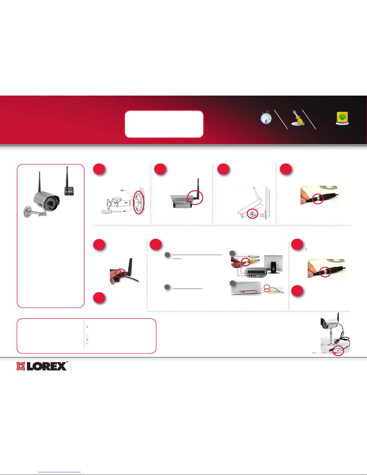
A. Connect the Camera
NOTE: Wireless cameras require a power
source to operate.
NOTE: Before you install a camera, carefully
plan where and how it will be positioned, and
where you will route the cable that connects
the camera to the power adaptor. Before
starting permanent installation, verify its
performance by observing the image on
a monitor when the camera is positioned
where it will be permanently installed.
NOTE: When adding cameras that were not
included in the original box, you will need to
pair up the camera with the receiver. Please
refer to the Camera Pairing Section of the
User Manual.
B. Connect the Receiver to an Observation System / DVR for recording or TV for large screen viewing**
1
Observation Monitor or DVR with
BNC:
Attach included RCA/BNC adaptor to
RCA cable and plug into Observation
Monitor or DVR. Connect the Audio
end of the RCA cable to the Audio
input of the Observation Monitor or
DVR.
1
Connect one end of the
Receiver Power Adaptor to
the receiver and the other
end to an electrical outlet.
4
TV with RCA Inputs:
Connect the RCA Video and Audio
ends of the RCA Audio/Video cable
to the Video and Audio inputs on
your TV.
2
** Requires viewing/recording device with
RCA Video or BNC Video input. Viewing/
Recording device sold separately.
1
3
View your Camera on any Observation Monitor with
BNC inputs or TV with RCA inputs**.
Connect power adaptor to local
120V AC power outlet
Mount camera stand to
the wall
1
4
Connect one end of the camera
Power Adaptor to the camera
and the other end to an
electrical outlet.
Connect the Wireless
Antenna to the camera.
2
3
Secure Camera to the
Stand.
2
The System comes with a camera that has already been paired. The Pairing Function assigns each camera
to a different channel on the Wireless Receiver (up to 4 Cameras), and is necessary for configuring additional
cameras. By default, the camera included with the system appears on channels 1 on the wireless receiver.
Please refer to the included Owner’s Manual for detailed steps.
C. Adding Additional Cameras
OPTIONAL
Take the double
sided tape supplied
to securely attach
the receiver to a flat
surface.
2
OPTIONAL
Attach the included
Wireless Antenna
to the receiver by
screwing it on.
Press the “Pair” button to
scroll through the different
camera views.
5
Pairing Button
www.lorexcctv.com
LW2201 Series Quick Start Guide_R1 Page 2
It’s all on the Web
For detailed setup information, please
refer to your User’s Manual. For
additional information and accessory
purchases, please visit our website
www.lorexcctv.com/support
R E G I S T E R N O W !
TO RECEIVE 3 MONTHS
WARRANTY EXTENSION
Visit: www.lorexcctV.com and click
on “warranty registration”
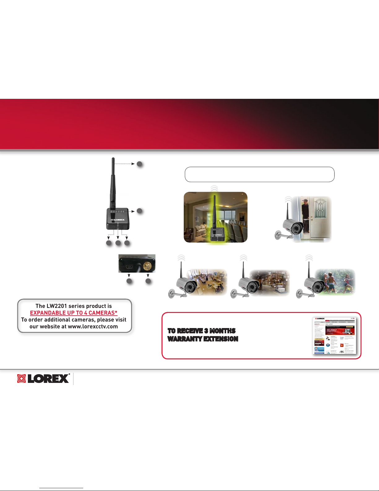
The LW2201 series product is
EXPANDABLE UP TO 4 CAMERAS*
To order additional cameras, please visit
our website at www.lorexcctv.com
D. Receiver Function Buttons
1. Wireless Antenna: Connects to the back of
the receiver.
2. Channel LEDs: When lit in green, indicates
the active viewing mode.
3. VGA/QVGA* button: Press to switch
between VGA and QVGA video resolutions;
press and hold for several seconds to
enable/disable Auto Scan.
4. Front LED: Lit in green to indicate power to
the receiver.
5. Pair: Press to switch between CH1~4, Quad
split-screen mode, and Auto-Scan; press
and hold to pair a camera to the receiver.
6. USB Port: Not used.
7. Antenna Jack: Connection for the wireless antenna.
1
2
43 5
ULTRA DIGITAL WIRELESS, QUAD
SURVEILLANCE SYSTEM
LW2201 SERIES - QUICK START GUIDE
©2008 Lorex Technology Inc.
As our product is subject to continuous improvement, Lorex Technology &
subsidiaries reserve the right to modify product design, specifications, prices &
warranty without notice and without incurring any obligation. E&OE
*NOTE: You can install additional cameras (maximum of 4 cameras).
When adding cameras that were not included in the original box, you
will need to pair up the cameras with the receiver. Refer to the camera
pairing section of the included user manual for more details.
*Images simulated.
*VGA (Video Graphics Array) has a resolution of 640 x 480;
QVGA (Quarter Video Graphics Array) has a resolution of
320 x 240.
6
7
4 Camera Digital Wireless Monitoring System
Family Room
Front Door
Camera 1
Receiver
Day Care
Warehouse
Backyard
Camera 2
Camera 3
Camera 4
Office
 Loading...