

Lorex LH030 ECO BLACKBOX3 SERIES Instruction Manual

Instruction Manual
LH030 ECO BLACKBOX3
SERIES


Instruction Manual
LH030 ECO BLACKBOX3
SERIES
#LX400008; r. 2.0/12067/12067; en-US
iii
Thank you for purchasing this product. Lorex is committed to providing our customers with a high quality,
reliable security solution.
This manual refers to the following models:
LH0304 (4-channel)
LH0308 (8-channel)
LH0316 (16-channel)
For the latest online manual, downloads and product updates, and to learn about our complete line of
accessory products, please visit our website at:
www.lorextechnology.com
WARNING
RISK OF ELECTRIC SHOCK
DO NOT OPEN
WARNING: TO REDUCE THE RICK OF ELECTRIC SHOCK DO NOT REMOVE
COVER. NO USER SERVICABLE PARTS INSIDE.
REFER SERVICING TO QUALIFIED SERVICE PERSONNEL.
The lightning flash with arrowhead symbol, within an equilateral
triangle, is intended to alert the user to the presence of uninsulated
"dangerous voltage" within the product’s enclosure that may be of
sufficient magnitude to constitute a risk of electric shock.
The exclamation point within an equilateral triangle is intended to
alert the user to the presence of important operating and
maintenance (servicing) instructions in the literature accompanying
the appliance.
WARNING: TO PREVENT FIRE OR SHOCK HAZARD, DO NOT EXPOSE THIS UNIT
TO RAIN OR MOISTURE.
CAUTION: TO PREVENT ELECTRIC SHOCK, MATCH WIDE BLADE OF THE PLUG
TO THE WIDE SLOT AND FULLY INSERT.
#LX400008; r. 2.0/12067/12067; en-US
iv

Table of contents
1 Important Safeguards ........... ............ ............ ....... ........................ ........1
1.1 General Precautions ....... ............ ............ ............ ................... ..... .1
1.2 Installation........... ............ ............ ........................ ....... ............ ...1
1.3 Service ........................ ............ ............ ............ ....... ............ ......3
1.4 Use....... ................... ............ ............ ............ ....... ..................... 3
2 LH030 Series Features .... ................... ............ ............ ............ ....... ....... 4
3 Getting Started (LH030 Series). ............ ............ ................... ............ ......5
4 Front Panel (LH030 Series) ........... ....... ..... ................... ............ ............ .6
5 Rear Panel (LH030 Series) ..................... ....... ............ ............ ............ ....7
6 Basic Setup (LH030 Series) ....... ............ ................... ............ ............ ....9
6.1 Step 1: Connect the BNC Cameras... ............ ............ ............ ....... ...9
6.2 Step 2: Connect the Mouse..... ............ ............ ............ .................. 9
6.3 Step 3: Connect the Ethernet Cable .. ........................ ....... ............ ...9
6.4 Step 4: Connect the Monitor..... ............ ............ ............ ....... ..........9
6.5 Step 5: Connect the Power Adapter and Power on the DVR........ ........ 10
6.6 Step 6: Upgrade Firmware to Latest Version (if Available) ......... ....... .. 10
6.7 Step 7: Verify Camera Image .... ............ ............ ................... ........ 11
6.8 Step 8: Set the Time .. ............ ............ ....... ........................ ......... 11
6.9 Default System Password & Port Numbers .. ................... ............ .... 11
6.9.1 Lorex Stratus Connectivity........ ........................ ....... ......... 12
6.10 Quick Access to System Information . ....... ........................ ............ . 12
6.11 Connecting Cameras .. ............ ............ ............ ................... ........ 12
6.11.1 Installing Cameras... ............ ............ ................... ............ 12
6.11.2 Connecting BNC Cameras to your DVR ......... ............ ......... 13
6.11.3 Connecting and Removing BNC Cables ....... ............ ........... 14
7 Mouse Control ...... ............ ............ ................... ............ ............ ......... 15
8 Remote Control ........... ............ ............ ............ ................... ..... ....... ... 16
9 Using the On-Screen Display .. ................... ............ ............ ............ ..... 18
9.1 Using the Menu Bar............... ....... ............ ............ ............ ......... 18
9.2 Using the Virtual Keyboard and Mini-Keyboard.......... ..... ....... .......... 19
9.3 Using the Zoom Mode........... ............ ............ ....... ..... ................. 20
9.4 Using Picture in Picture (PIP) Mode ............. ............ ............ ......... 20
10 Setting the Date and Time.... ............ ............ ............ ............ ....... ........ 22
10.1 Configuring Daylight Savings Time (DST)..... ............ ............ .......... 22
10.2 Using a NTP Server to set your System Time ........... ....... ............ .... 23
11 Recording.. ............ ............ ............ ........................ ....... ............ ........ 25
11.1 Recording Audio.......... ....... ..... ................... ............ ............ ...... 25
12 Playback ............. ............ ........................ ....... ............ ............ .......... 26
12.1 Playing Back Recorded Video ............. ............ ............ ............ .... 26
12.1.1 Using Playback Controls ...... ............ ............ ............ ....... . 27
12.1.2 Finding Events in the Playback Bar ...... ............ ............ ...... 28
12.1.3 Controlling the Time Range of the Playback Bar ............ ....... . 29
12.1.4 Using Zoom in Playback Mode . ............ ....... ..... ................. 29
12.2 Quick Playback ......... ............ ............ ............ ................... ........ 30
13 Backup......... ............ ....... ..... ................... ............ ............ ............ ..... 32
13.1 Backing Up Video ....... ........................ ....... ............ ............ ....... 32
13.2 Using Video Clip Backup ......... ............ ............ ............ ............... 33
13.3 Viewing Backed Up Video.................. ................... ............ .......... 34
#LX400008; r. 2.0/12067/12067; en-US
v

Table of contents
14 Managing Passwords........ ............ ............ ................... ..... ....... .......... 35
14.1 Changing Passwords... ....... ........................ ............ ............ ....... 35
14.2 Adding Users .... ............ ............ ....... ..... ................... ............ .... 36
15 Using the Main Menu .. ............ ............ ....... ..... ................... ............ .... 39
15.1 Display ........... ..... ....... ............ ............ ....... ..... ................... ..... 40
15.1.1 Configuring Custom Channel Names ....... ....... ............ ........ 40
15.1.2 Changing the Position of the Channel Name. ............ ............ 40
15.1.3 Adjusting Camera Color Settings ...... ....... ........................ .. 40
15.1.4 Enabling Covert Recording ..... ....... ............ ............ ........... 41
15.1.5 Configuring the Time and Recording Time Display......... ........ 41
15.1.6 Configuring Sequence Time . ........................ ............ ........ 41
15.1.7 Changing the Video-out Resolution .... ............ ............ ........ 42
15.1.8 Restoring the System’s Resolution if you see a Blank
Screen ......... ....... ............ ............ ............ ............ .........42
15.1.9 Adjusting Menu Transparency ........... ............ ............ ....... . 43
15.1.10 Adjusting the Video Margin... ............ ............ ............ ....... . 43
15.1.11 Adding Privacy Zones ................ ........................ ............ . 43
15.1.12 Creating a Custom Split-screen Display ....... ................... .... 44
15.2 Record ....... ............ ............ ............ ....... ........................ ......... 46
15.2.1 Configuring Pre-recording Settings.. ............ ............ ....... .... 46
15.2.2 Configuring the Recording Schedule (Continuous, Motion,
Alarm) .............. ........................ ............ ........................ 46
15.2.3 Enabling Audio Recording........ ............................... ......... 47
15.2.4 Configuring Recording Quality, Resolution, and Video
Frame Rate .... ..... ................... ............ ............ ............ ...48
15.3 Search ....... ........................ ....... ............ ............ ............ ......... 50
15.3.1 Using the Event Search ........... ........................ ....... ......... 50
15.3.2 Using the Log Search..... ............ ............ ............ ............. 51
15.4 Network................. ..... ....... ............ ............ ............ ................. 52
15.4.1 Configuring Network Type: DHCP & Static IP...... ............ ...... 52
15.4.2 Enabling Auto Port Forwarding ................ ............ ............ .. 52
15.4.3 Changing the DVR’s Client and HTTP Port... ................... ..... 52
15.4.4 Adjusting Remote Connectivity Streaming Rates ............ ....... 53
15.4.5 Setting up Email Notification ......... ............ ............ ....... ..... 54
15.4.6 Configuring DDNS settings........... ............ ............ ....... ..... 55
15.5 Alarm ...... ..... ....... ............ ............ ............ ................... ............ 56
15.5.1 Configuring Motion Detection.................... ............ ............ 56
15.5.2 Configuring Alarm Settings ............ ............ ....... ............ .... 57
15.6 Device.................. ............ ............ ............ ....... ....................... 59
15.6.1 Formatting the Hard Drive . ............ ................... ............ .... 59
15.6.2 Configuring Overwrite ............. ..... ....... ............ ............ .... 59
15.6.3 Formatting USB Flash Drives . ............ ................... ............ 60
15.7 System ............ ............ ................... ............ ............ ............ .... 61
15.7.1 Changing Date Format .... ............ ............ ............ ............ 61
15.7.2 Changing Time Format ....... ............ ............ ............ ......... 61
15.7.3 Changing the System Language .. ............ ............ ............ .. 61
15.7.4 Changing Video Output - NTSC & PAL ....... ............ ............. 61
15.7.5 Configuring Menu Time Out and Auto Logout ......... ............ .. 61
15.7.6 Adding Users & Changing the Admin Password ........... ......... 61
15.7.7 Viewing System Information...... ........................ ....... ......... 62
15.7.8 Setting the Remote Control ID... ............ ............ ............ .... 62
#LX400008; r. 2.0/12067/12067; en-US
vi

Table of contents
15.8 Advanced.......... ................... ............ ............ ............ ....... ........ 63
15.8.1 Configuring Firmware Upgrades .................. ............ .......... 63
15.8.2 Upgrading the System Firmware Using a USB Thumb
Drive........ ................... ............ ............ ............ ............ .63
15.8.3 Restoring to Factory Default Settings .... ............ ............ ...... 64
15.8.4 Restarting or Shutting Down the DVR ....... ....... ................... 65
15.8.5 Configuring System Warnings ............. ............ ............ ...... 66
15.8.6 Saving Your System Configuration to a USB Flash
Drive........ ................... ............ ............ ............ ............ .67
15.8.7 Loading a System Configuration from a USB Flash
Drive........ ................... ............ ............ ............ ............ .67
16 Connecting to Your DVR Over the Internet on PC or Mac........ ............ ..... 69
16.1 System Requirements...... ............ ............ ................... ..... .......... 69
16.2 Step 1 of 3: Connect your DVR to Your Router ......... ............ ............ 69
16.3 Step 2 of 3: Obtain the DVR’s Device ID... ................... ............ ....... 70
16.4 Step 3 of 3: Connect to the DVR Over the Internet...................... ...... 71
17 Using the PC/Mac Client Software .............. ....... ............ ............ .......... 73
17.1 Changing Viewing Modes .... ............ ............ ............ ....... ............ 74
17.2 Taking Screen Shots.......... ............ ............................... ............ . 74
17.3 Recording Video..... ............ ............ ............ ........................ ...... 74
17.4 Showing / Hiding Channels . ........................ ....... ............ ............ 75
17.5 Viewing the Bit Rate . ........................ ................... ............ .......... 75
17.6 Changing the Save Directory of Screenshots or Recorded
Video........... ............ ....... ..... ................... ............ ............ ........76
17.7 Changing the Format of Recorded Video (PC Only) ....... ............ ....... 76
17.8 Configuring PTZ Settings........... ............ ....... ........................ ...... 77
17.9 Video Playback ......... ............ ............ ............ ................... ........ 78
17.9.1 Video Playback Controls ....................... ............ ............... 80
17.10 Configuring Display Settings ............................ ............ ............ ... 81
17.11 Configuring Privacy Zone Settings ........... ............................... ...... 81
17.12 Configuring Recording Parameters ........... ............ ............ ............ 82
17.13 Configuring the Recording Schedule ...... ............ ................... ........ 82
17.14 Configuring System Recording Quality ...... ............ ............ ............ 83
17.15 Configuring Basic Network Settings ........... ............ ................... .... 84
17.16 Configuring the System Substream ....... ........................ ....... ......... 84
17.17 Configuring Email Notification Settings .. ..... ................... ............ .... 85
17.18 Configuring DDNS Settings... ............ ............ ........................ ...... 86
17.19 Configuring Motion Detection Settings ....... ....... ..... ................... ..... 87
17.20 Configuring your System to "Beep" During Motion . ............ ............ ... 88
17.21 Configuring Alarm Notifications .............. ............ ........................ .. 88
17.22 Configuring Hard Drive Recording Mode ........... ....... ..... ................. 89
17.23 Configuring PTZ Parameters . ....... ..... ................... ............ ........... 89
17.24 Configuring the System Time and Date ....... ............ ....... ............ .... 90
17.25 Changing the System’s Menu Time Out .... ............ ............ ............. 91
17.26 Configuring System User Accounts.......... ........................ ....... ...... 91
17.27 Viewing System Information .................. ............ ........................ .. 92
17.28 Configuring Firmware Upgrades ....... ............ ............ ............ ....... . 92
17.29 Manually Upgrading System Firmware......... ....... ............ ............ ... 92
17.30 Restoring Default Settings . ............ ............ ....... ........................ .. 93
17.31 Configuring Event Settings ....... ............ ............ ................... ........ 94
#LX400008; r. 2.0/12067/12067; en-US
vii

Table of contents
18 Mobile Apps: Accessing your DVR Using a Mobile Device ...... ............ .... 95
18.1 Supported Apps and Platforms .. ............ ............ ....... ................... 95
18.2 iPhone..................... ....... ............ ............ ............ ............ ....... . 95
18.2.1 Connecting to Your System Using Lorex Eco Stratus ............ .. 95
18.2.2 Lorex Eco Stratus Interface . ............ ........................ ....... .. 97
18.2.3 Taking Screenshots .. ............ ............ ............ ............ ...... 98
18.2.4 Taking Manual Recordings .. ............ ....... ........................ .. 98
18.2.5 Using PTZ Controls . ............ ............ ............ ....... ............ 98
18.2.6 Using Remote Playback Mode on iPhone .... ............ ............ 99
18.2.7 Viewing Screenshots ........... ............ ............ ....... .......... 101
18.2.8 Viewing Manual Recordings ........... ....... ............ ............ . 102
18.2.9 Using Device Manager to Manage DVR’s .... ............ .......... 103
18.3 iPad ............ ............ ................... ............ ............ ............ ...... 104
18.3.1 Prerequisites:... ....... ..... ................... ............ ............ .... 104
18.3.2 Connecting to your DVR ....... ............ ................... .......... 104
18.3.3 Live View Interface ....................... ....... ............ ............ . 107
18.3.4 Taking Screenshots .. ............ ............ ............ ............ .... 107
18.3.5 Taking Manual Recordings .. ............ ....... ........................ 107
18.3.6 Using PTZ Controls . ............ ............ ............ ....... .......... 108
18.3.7 Using Remote Playback Mode ...... ............ ............ .......... 108
18.3.8 Viewing Screenshots ........... ............ ............ ....... .......... 110
18.3.9 Viewing Manual Recordings ........... ....... ............ ............ . 111
18.3.10 Using Device Manager to Manage DVRs ............ ............ ... 112
18.3.11 Managing Favorites .. ............ ............ ....... ..................... 113
18.4 Android ......... ....... ............ ............ ............ ........................ .... 114
18.4.1 Connecting to Your System Using Lorex Eco Stratus ............ 114
18.4.2 Lorex Eco Stratus Interface . ............ ........................ ....... 116
18.4.3 Taking Screenshots .. ............ ............ ............ ............ .... 117
18.4.4 Taking Manual Recordings .. ............ ....... ........................ 117
18.4.5 Using PTZ Controls . ............ ............ ............ ....... .......... 117
18.4.6 Using Remote Playback Mode on Android . ............ ............ 118
18.4.7 Viewing Screenshots ........... ............ ............ ....... .......... 120
18.4.8 Viewing Manual Recordings ........... ....... ............ ............ . 122
18.4.9 Using Device Manager to Manage DVR’s .... ............ .......... 123
19 Lorex Player 11: Playing Backed up Video on PC .. ....... ........................ 125
19.1 Running Lorex Player 11...... ............ ............ ............ ....... .......... 125
19.2 Lorex Player 11 Interface Overview ....... ..... ................... ............ .. 126
19.2.1 About the Advanced Config Menu ....... ............ ............ ..... 126
19.3 Converting Backed Up Video to AVI Files ...... ........................ ....... 127
20 Lorex Player for Mac: Viewing Backed up Video on Mac ......... ............ .. 129
20.1 Opening Individual Video Files..... ........................ ............ .......... 129
20.2 Loading Multiple Video Files. ............................... ............ .......... 129
20.3 Lorex Player for Mac Interface ................ ............ ............ ........... 130
21 Connecting a PTZ Camera (LH030 Series) ......... ............ ....... ............ .. 131
21.1 Configuring PTZ Settings........... ............ ....... ........................ .... 131
21.2 Using the PTZ Menu (Local DVR) ............ ............ ............ ........... 132
21.3 PTZ Presets and PTZ Cruise .. ............ ............ ....... ..... ............... 133
21.3.1 PTZ Preset Controls .. ............ ................... ..... ....... ........ 133
21.3.2 Setting PTZ Presets........ ................... ..... ................... ... 133
21.3.3 Selecting PTZ Presets. ............ ....... ........................ ....... 134
#LX400008; r. 2.0/12067/12067; en-US
viii

Table of contents
21.3.4 Deleting PTZ Presets ...... ................... ..... ....... ............ ... 134
21.3.5 Starting / Stopping PTZ Cruise ........... ................... .......... 134
22 Connecting Additional External Monitors (LH030 Series) . ............ ........ 135
22.1 Connecting the DVR to TV RCA Ports ........... ............ ............ ...... 135
22.2 Customizing the Channel Arrangement on the External
Monitor .................. ............ ............ ............ ................... ........ 135
23 Recording Audio (LH030 Series) .. ........................ ............ ................. 137
24 Replacing the Hard Drive (LH030 Series).......... ....... ..... ................... ... 138
24.1 Removing the Hard Drive...... ..... ................... ............ ............ .... 138
24.2 Installing the Hard Drive .. ............ ............ ............ ................... .. 139
24.3 Formatting the Hard Drive ............ ............ ............ ................... .. 140
25 DDNS Setup (Advanced) ........... ............ ....... ............ ............ ............ 142
25.1 Accessing your DVR within a local network (LAN) .. ....... ................. 142
25.1.1 Step 1 of 3: Connect your DVR to the Local Area
Network...... ............ ................... ............ ............ ......... 142
25.1.2 Step 2 of 3: Obtain the DVR’s Local IP Address ................... 143
25.1.3 Step 3 of 3: Connect to the DVR’s Local IP Address .. ........... 143
25.2 DDNS Setup—Access your DVR Remotely over the Internet ........... . 145
25.2.1 Step 1 of 4: Port Forwarding .............. ....... ............ .......... 145
25.2.2 Step 2 of 4: Create a DDNS Account . ............ ............ ....... 146
25.2.3 Step 3 of 4: Enable DDNS on the DVR .. ............ ............ .... 150
25.2.4 Step 4 of 4: Connect to the DVR’s DDNS Address ......... ...... 150
26 Troubleshooting ..................... ............ ............ ............ ................... .. 153
27 LH030 Series System Specifications..... ..... ....... ............ ............ ......... 156
28 Notices.............. ..... ....... ............ ............ ............ ............ ....... .......... 159
28.1 FCC/IC Notice........ ............ ............ ............ ....... ..................... 159
28.2 Modification........ ............ ............ ................... ........................ 159
28.3 ROHS .............. ....... ............ ............ ............ ............ ....... ...... 159
#LX400008; r. 2.0/12067/12067; en-US
ix

1
Important Safeguards
In addition to the careful attention devoted to quality standards in the manufacturing process of your product, safety is a major factor in the design of every instrument. However,
safety is your responsibility too. This sheet lists important information that will help to ensure your enjoyment and proper use of the product and accessory equipment. Please read
them carefully before operating and using your product.
1.1 General Precautions
1. All warnings and instructions in this manual should be followed.
2. Remove the plug from the outlet before cleaning. Do not use liquid aerosol detergents.
Use a water-dampened cloth for cleaning.
3. Do not use this product in humid or wet places.
4. Keep enough space around the product for ventilation. Slots and openings in the storage cabinet should not be blocked.
5. It is highly recommended to connect the product to a surge protector to protect from
damage caused by electrical surges. It is also recommended to connect the product to
an uninterruptible power supply (UPS), which has an internal battery that will keep the
product running in the event of a power outage.
CAUTION
Maintain electrical safety. Power line operated equipment or accessories connected to this product
should bear the UL listing mark or CSA certification mark on the accessory itself and should not be modified so as to defeat the safety features. This will help avoid any potential hazard from electrical shock or
fire. If in doubt, contact qualified service personnel.
1.2 Installation
1. Read and Follow Instructions - All the safety and operating instructions should be
read before the product is operated. Follow all operating instructions.
2. Retain Instructions - The safety and operating instructions should be retained for future reference.
3. Heed Warnings - Comply with all warnings on the product and in the operating
instructions.
4. Polarization - Do not defeat the safety purpose of the polarized or grounding-type
plug.
A polarized plug has two blades with one wider than the other.
A grounding type plug has two blades and a third grounding prong.
The wide blade or the third prong are provided for your safety.
If the provided plug does not fit into your outlet, consult an electrician for replacement
of the obsolete outlet.
#LX400008; r. 2.0/12067/12067; en-US
1

1
Important Safeguards
5. Power Sources - This product should be operated only from the type of power source
indicated on the marking label. If you are not sure of the type of power supplied to your
location, consult your video dealer or local power company. For products intended to
operate from battery power, or other sources, refer to the operating instructions.
6. Overloading - Do not overload wall outlets or extension cords as this can result in the
risk of fire or electric shock. Overloaded AC outlets, extension cords, frayed power
cords, damaged or cracked wire insulation, and broken plugs are dangerous. They
may result in a shock or fire hazard. Periodically examine the cord, and if its appearance indicates damage or deteriorated insulation, have it replaced by your service
technician.
7. Power-Cord Protection - Power supply cords should be routed so that they are not
likely to be walked on or pinched by items placed upon or against them. Pay particular
attention to cords at plugs, convenience receptacles, and the point where they exit
from the product.
8. Surge Protectors - It is highly recommended that the product be connected to a
surge protector. Doing so will protect the product from damage caused by power
surges. Surge protectors should bear the UL listing mark or CSA certification mark.
9. Uninterruptible Power Supplies (UPS) - Because this product is designed for continuous, 24/7 operation, it is recommended that you connect the product to an uninterruptible power supply. An uninterruptible power supply has an internal battery that will
keep the product running in the event of a power outage. Uninterruptible power supplies should bear the UL listing mark or CSA certification mark.
10. Ventilation - Slots and openings in the case are provided for ventilation to ensure reliable operation of the product and to protect it from overheating. These openings must
not be blocked or covered. The openings should never be blocked by placing the product on a bed, sofa, rug, or other similar surface. This product should never be placed
near or over a radiator or heat register. This product should not be placed in a built-in
installation such as a bookcase or rack unless proper ventilation is provided and the
product manufacturer’s instructions have been followed.
11. Attachments - Do not use attachments unless recommended by the product manufacturer as they may cause a hazard.
12. Water and Moisture - Do not use this product near water — for example, near a bath
tub, wash bowl, kitchen sink or laundry tub, in a wet basement, near a swimming pool
and the like.
13. Heat - The product should be situated away from heat sources such as radiators, heat
registers, stoves, or other products (including amplifiers) that produce heat.
14. Accessories - Do not place this product on an unstable cart, stand, tripod, or table.
The product may fall, causing serious damage to the product. Use this product only
with a cart, stand, tripod, bracket, or table recommended by the manufacturer or sold
with the product. Any mounting of the product should follow the manufacturer’s instructions and use a mounting accessory recommended by the manufacturer.
15. Camera Extension Cables – Check the rating of your extension cable(s) to verify
compliance with your local authority regulations prior to installation.
16. Mounting - The cameras provided with this system should be mounted only as instructed in this guide or the instructions that came with your cameras, using the provided mounting brackets.
#LX400008; r. 2.0/12067/12067; en-US
2

1
Important Safeguards
17. Camera Installation - Cameras are not intended for submersion in water. Not all cameras can be installed outdoors. Check your camera environmental rating to confirm if
they can be installed outdoors. When installing cameras outdoors, installation in a
sheltered area is required.
1.3 Service
1. Servicing - Do not attempt to service this product yourself, as opening or removing
covers may expose you to dangerous voltage or other hazards. Refer all servicing to
qualified service personnel.
2. Conditions Requiring Service - Unplug this product from the wall outlet and refer
servicing to qualified service personnel under the following conditions:
• When the power supply cord or plug is damaged.
• If liquid has been spilled or objects have fallen into the product.
• If the product has been exposed to rain or water.
• If the product has been dropped or the cabinet has been damaged
• If the product does not operate normally by following the operating instructions. Ad-
just only those controls that are covered by the operating instructions. Improper adjustment of other controls may result in damage and will often require extensive
work by a qualified technician to restore the product to its normal operation.
• When the product exhibits a distinct change in performance. This indicates a need
for service.
3. Replacement Parts - When replacement parts are required, have the service technician verify that the replacements used have the same safety characteristics as the original parts. Use of replacements specified by the product manufacturer can prevent fire,
electric shock, or other hazards.
4. Safety Check - Upon completion of any service or repairs to this product, ask the
service technician to perform safety checks recommended by the manufacturer to determine that the product is in safe operating condition.
1.4 Use
1. Cleaning - Unplug the product from the wall outlet before cleaning. Do not use liquid
cleaners or aerosol cleaners. Use a damp cloth for cleaning.
2. Product and Cart Combination - When product is installed on a cart, product and
cart combination should be moved with care. Quick stops, excessive force, and uneven surfaces may cause the product and cart combination to overturn.
3. Object and Liquid Entry - Never push objects of any kind into this product through
openings as they may touch dangerous voltage points or “short-out” parts that could
result in a fire or electric shock. Never spill liquid of any kind on the product.
4. Lightning - For added protection of this product during a lightning storm, or when it is
left unattended and unused for long periods of time, unplug it from the wall outlet and
disconnect the antenna or cable system. This will prevent damage to the product due
to lightning and power line surges.
#LX400008; r. 2.0/12067/12067; en-US
3

2
LH030 Series Features
• Tablet / smartphone viewing and playback1.
• Lorex Stratus Connectivity - 3 step setup.
• Superior 960H Resolution - 34% more detailed and true-to-life images
• High-definition HDMI output
3
.
• 24/7 security-grade hard drive.
• Instant email alerts with snap shot attachment.
• Real-time recording: 4ch @ 960H (960x480), 8ch @D1 (720x480), 16ch @ WCIF
(480x240).
• Continuous, scheduled and motion recording.
• Advanced mobile apps with live viewing, playback, video recording, and snap shot.
• PC and Mac compatible.
• H.264 video compression
4
.
• HDMI cable included for simple connection to HDTVs.
• Pentaplex operation - view, record, playback, back up & remotely control the system
simultaneously.
• PTZ cameras supported (RS485). Remotely control through App.
• Accurate time stamps with NTP & Daylight Savings Time.
• 3 video outputs (HDMI, VGA and BNC) to connect multiple monitors.
• Automatic firmware upgrades over Internet ensure your system is secure and up to
5
date
.
Note
1. Requires a high speed internet connection and a router (not included). An upload speed of 1Mbps is
recommended for the best video performance. Up to 3 devices may connect to the system at the
same time. For the latest list of supported apps and devices, check
www.lorextechnology.com/support.
2. Optimized when used with 960H compatible cameras. DVR is backwards compatible and supports
different camera inputs: standard resolution and 960H.
3. High definition recording not supported, recording resolution is limited to a maximum of 960x480 per
channel. Image quality and resolution is dependent on the type of camera connected to the DVR.
4. Recording time may vary based on recording resolution & quality, lighting conditions and movement
in the scene.
5. Both firmware and software must be updated to latest version to ensure remote connectivity. Always
update to the latest software (available at www.lorextechnology.com) after upgrading the DVR
firmware.
BlackBox is used solely as a marketing term and does not imply that the product can survive fire or extreme conditions. Use product in accordance with the instructions provided. All trademarks belong to
their respective owners. No claim is made to the exclusive right to use the trademarks listed, other than
the trademarks owned by Lorex Corporation. We reserve the right to change models, configurations or
specifications without notice or liability. Product may not be exactly as shown. Images are simulated.
2
.
#LX400008; r. 2.0/12067/12067; en-US
4

3
Getting Started (LH030 Series)
The system comes with the following components:
DVR (Digital Video Recorder) 12V DC Power Supply
USB Mouse Ethernet Cable HDMI Cable
Quick Start Guides
Hard drive size, number of channels, and camera configuration may vary by model. Please
refer to your package for specific details. Check your package to confirm that you have received the complete system, including all components shown above.
Remote Control
(may not be exactly as shown)
#LX400008; r. 2.0/12067/12067; en-US
5

4
1 2 3 4
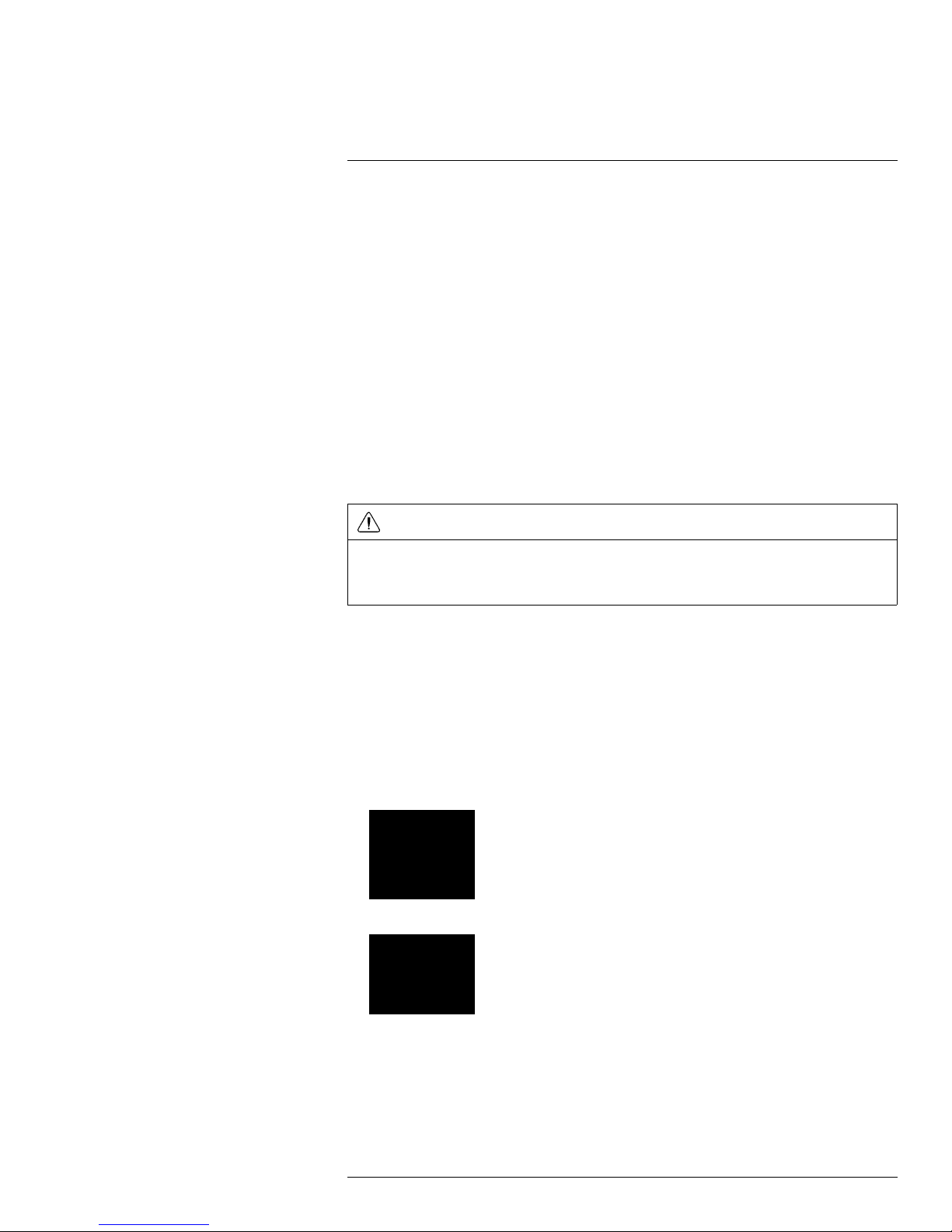
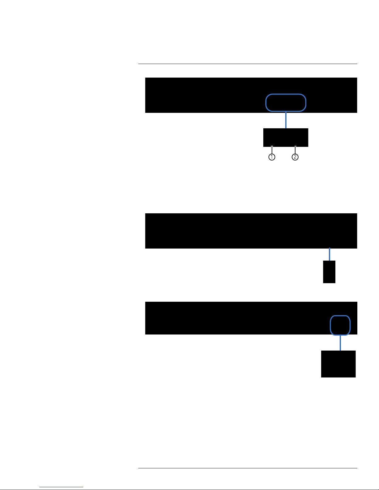
Front Panel (LH030 Series)
1. IR Sensor: IR receiver for the remote control.
2. PWR LED: Power indicator LED.
3. HDD LED: Hard disk activity LED.
4. USB Port: Connect a USB mouse (included) or USB flash drive (not included) for data
backup or firmware updates.
#LX400008; r. 2.0/12067/12067; en-US
6
5
0
1
020
30405
0608090100
7
0
1
020
30405
0608090100
7
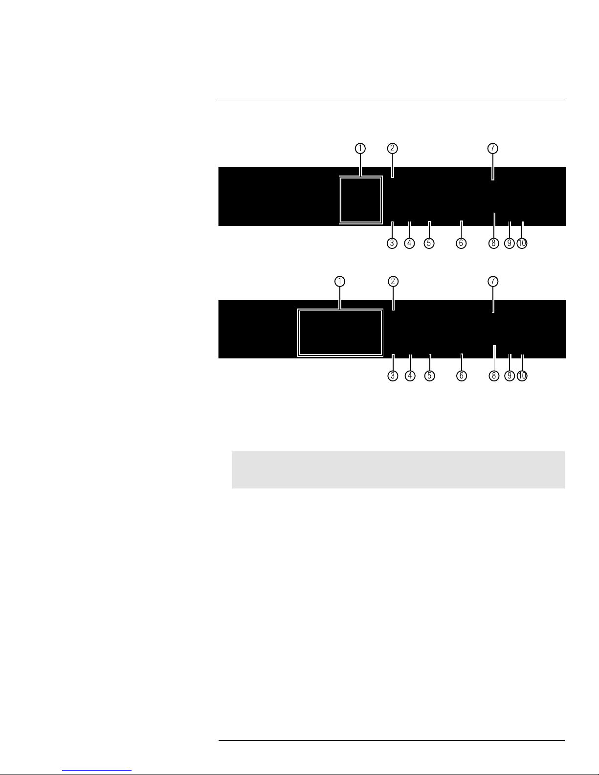
Rear Panel (LH030 Series)
4–Channel
8–Channel
1. Video Input: Connect BNC cameras.
2. Video Output: Outputs the DVR interface to a BNC connection. This allows you to see
your mouse cursor and have full control of the system on a secondary monitor. To
switch the mouse and system interface between BNC and VGA/HDMI monitors, press
0 three times on the remote control.
Note
Use a BNC to RCA adapter (not included) to connect the DVR to RCA inputs (i.e. for a TV
connection).
3. Audio Output: Output for 1 RCA audio channel (e.g. speakers).
4. Audio Input: Input for 2 RCA audio-enabled cameras (not included).
5. HDMI: Connect to an HDMI monitor or TV (not included) to view the system interface.
6. VGA: Connect a VGA monitor (not included) to view the system interface.
7. LAN: Connect a CAT 5 RJ45 Ethernet cable for local and remote connectivity.
8. USB Port: Connect a USB mouse (included) or USB flash drive (not included) for data
backup or firmware updates.
9. RS485: Connect compatible PTZ cameras (not included).
10. DC12V: Connect the included AC power adapter.
#LX400008; r. 2.0/12067/12067; en-US
7
5
0
1
020
3
0
50708010
060
4
090
12
0
11
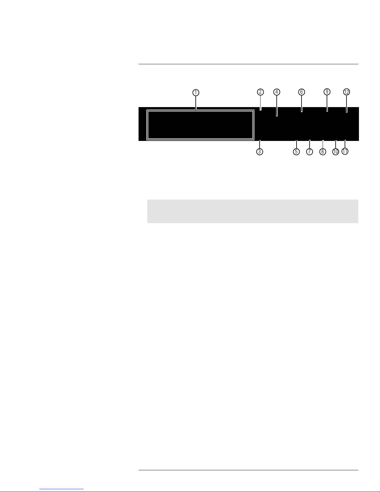
Rear Panel (LH030 Series)
16–Channel
1. Video Input: Connect BNC cameras.
2. Video Output: Outputs the DVR interface to a BNC connection. This allows you to see
your mouse cursor and have full control of the system on a secondary monitor. To
switch the mouse and system interface between BNC and VGA/HDMI monitors, press
0 three times on the remote control.
Note
Use a BNC to RCA adapter (not included) to connect the DVR to RCA inputs (i.e. for a TV
connection).
3. Audio Output: Output for 1 RCA audio channel (e.g. speakers).
4. Audio Input: Input for 4 RCA audio-enabled cameras (not included).
5. HDMI: Connect to an HDMI monitor or TV (not included) to view the system interface.
6. VGA: Connect a VGA monitor (not included) to view the system interface.
7. LAN: Connect a CAT 5 RJ45 Ethernet cable for local and remote connectivity.
8. USB Port: Connect a USB mouse (included) or USB flash drive (not included) for data
backup or firmware updates.
9. RS485/Alarm Block: Connect compatible PTZ cameras (not included) or alarm sensor devices (not included).
10. DC12V: Connect the included AC power adapter.
11. On / Off Switch: Turns the DVR on or off.
12. IR EXT: Service only; not supported.
#LX400008; r. 2.0/12067/12067; en-US
8

6
000
000
Basic Setup (LH030 Series)
6.1 Step 1: Connect the BNC Cameras
• Connect BNC cameras to the Video In ports on the rear panel of the DVR.
Push and twist the BNC connector clockwise to secure it to the BNC port
6.2 Step 2: Connect the Mouse
• Connect a USB mouse (included) to one of the USB ports.
6.3 Step 3: Connect the Ethernet Cable
• Connect an Ethernet cable (included) to the LAN port on the rear panel of the DVR.
Connect the other end of the Ethernet cable to a router on your network.
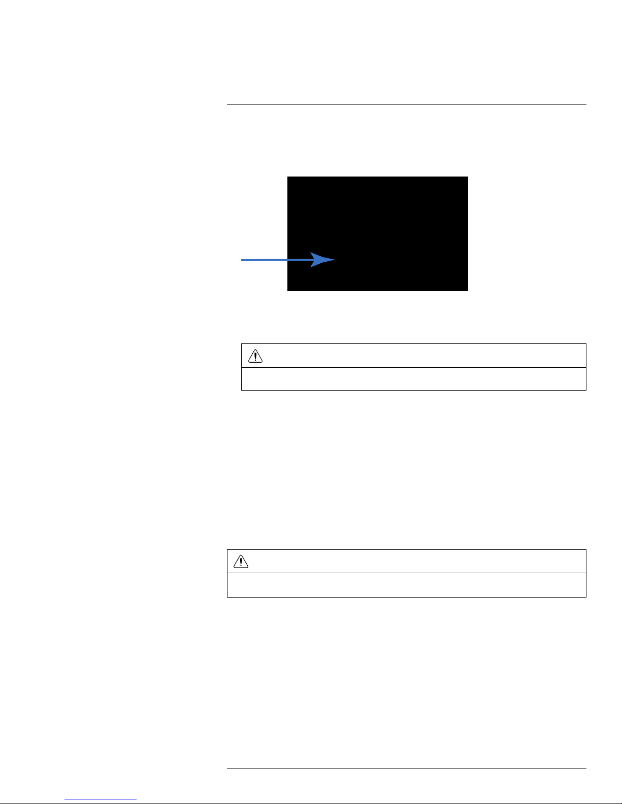
6.4 Step 4: Connect the Monitor
• Connect the included HDMI cable from the HDMI port to the TV or monitor (recom-
mended) OR;
• Connect a VGA cable (not included) from the VGA port to the monitor.
#LX400008; r. 2.0/12067/12067; en-US
9
6
0
1
2
0
0
Basic Setup (LH030 Series)
1. HDMI port.
2. VGA port.
6.5 Step 5: Connect the Power Adapter and Power on the DVR
• 4/8–channel models: Connect the included power adapter to the DC 12V port. Con-
nect the end of the power adapter to a wall socket or a surge protector.
• 16-channel models: Turn the power switch to I to turn on the DVR.
At startup, the system performs a basic system check and runs an initial loading sequence.
After a few moments, the system loads a live display view.
6.6 Step 6: Upgrade Firmware to Latest Version (if Available)
If a firmware upgrade is available, you will be asked to install it once the DVR starts up. It is
required to upgrade your system firmware and client software or mobile apps to the latest
version to enable remote connection to the system.
#LX400008; r. 2.0/12067/12067; en-US
10
6
0
Basic Setup (LH030 Series)
If a firmware upgrade is available:
1. After startup, a notification will appear asking you to upgrade the firmware. Click Yes to
upgrade.
2. Enter the system user name (default: admin) and password (default: 000000) and
click Apply. Wait for the firmware update to complete. The system will restart once the
firmware has been upgraded.
WARNING
DO NOT POWER OFF THE DVR OR DISCONNECT THE POWER CABLE DURING FIRMWARE
INSTALLATION
6.7 Step 7: Verify Camera Image
• Power on the cameras, and then verify the camera video quality before mounting the
cameras to a permanent location.
• Mount the cameras under a sheltered location. Always verify the outdoor rating of your
camera before installing it in a permanent location.
6.8 Step 8: Set the Time
• Set the system time and date for accurate video time stamps. Videos with inaccurate
times may not be valid as surveillance evidence.
• For details on setting the system time, see 10 Setting the Date and Time, page 22.
6.9 Default System Password & Port Numbers
CAUTION
By default, the system user name is admin and the password is 000000. It is essential that you create
your own password. For details, see 14 Managing Passwords, page 35.
The system requires a user name and password to log in to the system remotely using a
computer or mobile device. After logging on remotely the first time, you will be asked to
create a custom password for the system.
Local DVR and remote connectivity (LAN & Internet) user name and password:
• Username: admin
• Password: 000000
Default ports for DDNS remote access:
• Port 80 (HTTP port)
• Port 9000 (Client port)
#LX400008; r. 2.0/12067/12067; en-US
11
6
Basic Setup (LH030 Series)
6.9.1 Lorex Stratus Connectivity
This system features the exclusive Lorex Stratus Connectivity. This is a cloud service that
allows you to connect to your system over the Internet via a secure handshake with Lorex’s
servers. This means you can easily connect to your system without requiring any network
configuration.
For details on setting up your system to connect to the Internet using Lorex Stratus
Connectivity:
• See 16 Connecting to Your DVR Over the Internet on PC or Mac, page 69.
OR
• See 18 Mobile Apps: Accessing your DVR Using a Mobile Device, page 95.
Connectivity using Lorex’s free DDNS service is also available, but requires the ports listed
above to be port forwarded on your router.
6.10 Quick Access to System Information
To quickly open a window that displays vital system information:
• Press the
button on the remote control to open the System Information window.
OR
• Right-click and then click the Main Menu button (
). Login using the DVR user
name and password (the default user name is admin, and the default password is
000000). Then click System>Info.
6.11 Connecting Cameras
CAUTION
Cameras differ in terms of installation or mounting instructions. Please see the documentation that came
with your camera(s) for specific installation instructions.
Test the cameras before permanent installation. Plan where you will route the wiring for
the camera and where you will aim the camera.
Installation Tips
• Mount the camera where the lens is away from direct and intense sunlight.
• Plan your cable wiring so that it does not interfere with power lines or telephone lines.
• Ensure that the camera wiring is not exposed or easily cut.
• Mount the camera in an area that is visible, but out of reach.
• Avoid pointing the camera at a glass window to see outside, as this may result in a poor
image caused by glare from indoor / outdoor lighting conditions.
• Adjust the camera angle so that it covers an area with high traffic.
• In "high-risk" locations, have multiple cameras point in the same area. This provides
camera redundancy if a vandal attempts to damage the camera.
6.11.1 Installing Cameras
1. Mount the camera(s) to the desired mounting surface according to the instructions that
came with the camera(s). Choose a firm mounting surface.
Note
If you wish to mount cameras to drywall, it is recommended to use drywall anchors (not included).
#LX400008; r. 2.0/12067/12067; en-US
12

6
0
1
0
2
3
Basic Setup (LH030 Series)
2. Adjust the camera stand to ensure that the camera has a satisfactory view of the area
you would like to monitor. Stand configuration depends on the mounting surface you
have chosen (see below for suggested stand configurations).
Table Mount Wall Mount
Ceiling Mount
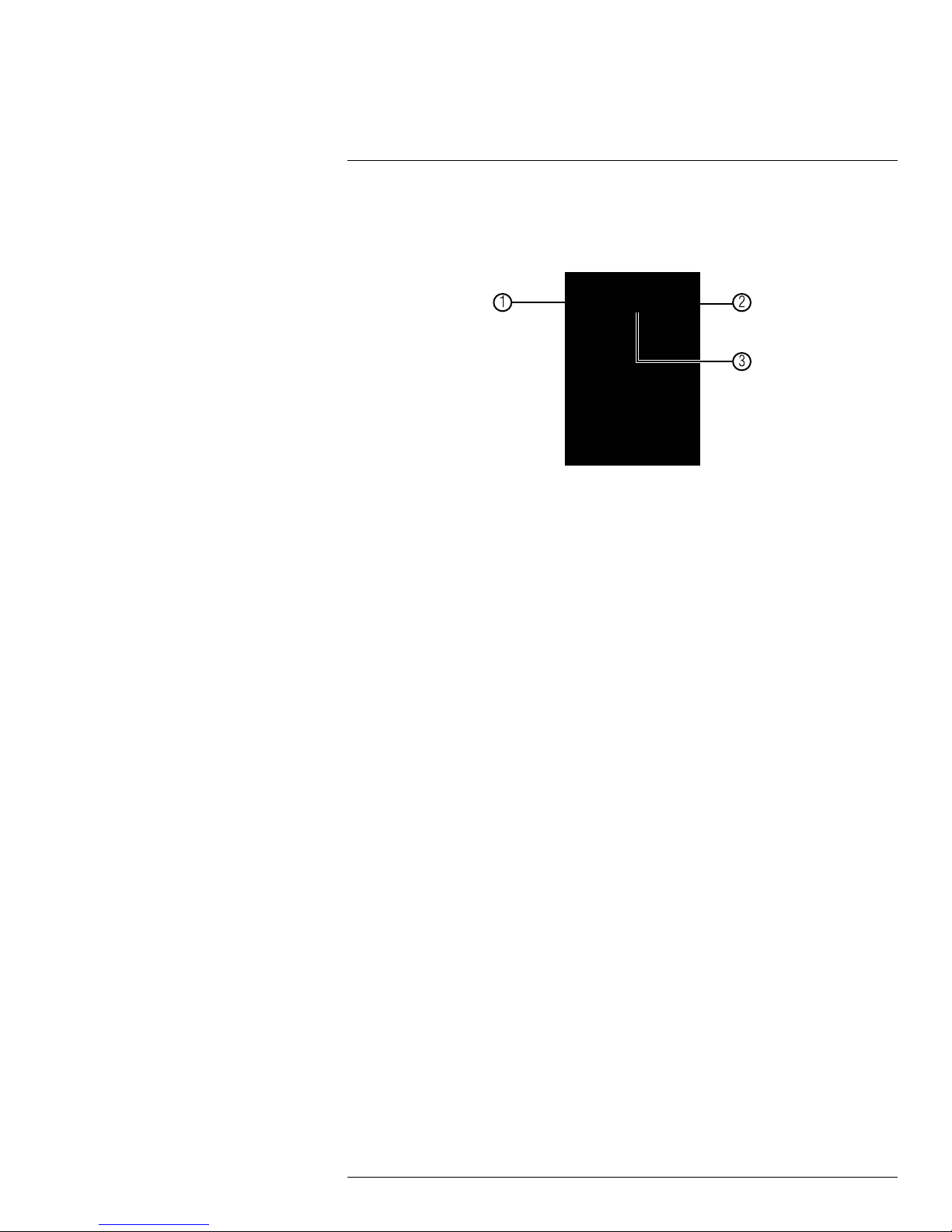
There are two connection points for certain cameras. Secure the stand to the top thread
for wall mounts or ceiling mounts. Secure the stand to the bottom thread for table mounts
or wall mounts.
1. Top Thread (Ceiling Mount, Wall Mount).
2. Bottom Thread (Table Mount).
3. Secure to camera thread.
Note
Camera model may not be exactly as shown.
6.11.2 Connecting BNC Cameras to your DVR
1. Connect the male power connector on the BNC extension cable to the female power
connector on the camera.
• Connect the BNC connector to the camera.
2. Connect the female power connector on the BNC extension cable to the power
adapter.
3. Connect the BNC connector to one of the Video Input ports on the rear panel of the
DVR.
4. Plug the camera power adapter to a power outlet.
#LX400008; r. 2.0/12067/12067; en-US
13

6
00000
00
NC
1
2
3
4
6
5
Basic Setup (LH030 Series)
Camera Installation Diagram
1. Camera.
2. End of extension cable with male power connector.
3. Extension cable.
4. End of extension cable with female power connector.
5. Camera power adapter.
6. DVR.
6.11.3 Connecting and Removing BNC Cables
BNC (Bayonet Nut Connector) is a special connector that locks on to the system port and
cannot be accidently removed.
To connect or remove a BNC connector:
• Push the BNC connector firmly into the BNC port and simultaneously twist the connec-
tor clockwise to tighten.
• To remove a BNC connector from a BNC port, push and simultaneously twist the con-
nector counter-clockwise to loosen the BNC connector.
#LX400008; r. 2.0/12067/12067; en-US
14
7
2
3
Mouse Control
The DVR is designed for mouse navigation. To use a USB mouse (included), connect the
mouse to a USB port on the DVR.
Use the mouse buttons to perform the following:
1. Left-Button:
• Click to select a menu option.
• During live viewing in Split-screen View, double-click on a channel to view the selected channel in
full-screen; double-click the channel again to return to Split-screen View.
2. Right-Button:
• Click to open the Menu Bar (see 9.1 Using the Menu Bar, page 18).
• In menus, use the right-button to go back / exit menus.
3. Scroll-Wheel: No function.
#LX400008; r. 2.0/12067/12067; en-US
15

8
0
1
2
3 5
6
ID
4
Remote Control
You can also control the DVR using the included remote control.
1. Number Keys (1~0): Press to select the desired channel in Full-screen View.
(16-channel models only) Press 1+0 for channel 10, 1+1 for channel 11, etc.
•
• MENU: Press to open the Main Menu. In menus, press to go back / exit menus.
• 0: Press 0 three times to show the mouse cursor on the BNC monitor or the monitor
2. Navigation Cursors: Press to navigate menus.
•
3. SUB MENU: Press to open the Menu Bar.
4. ID: Used to pair the remote control to a specific DVR. For details, see 15.7.8 Setting
the Remote Control ID, page 62.
5. MUTE: Press to mute/un-mute audio during Live Viewing and Playback Mode. Audiocapable cameras (not included) are required for audio recording and listen-in audio
functionality.
: In Live Viewing Mode, press to open Split-screen View. Press repeatedly to
switch between split-screen viewing modes.
connected with VGA/HDMI.
: Press to select menu items. In Live Viewing Mode, press to access System
Information.
#LX400008; r. 2.0/12067/12067; en-US
16

8
Remote Control
6. Playback Controls:
: In Playback Mode, press to fast forward/increase fast forward speed.
•
: In Playback Mode, press to rewind/increase rewind speed.
•
: In Live Viewing Mode, press to open the Search Menu to select video for
•
playback.
In Playback Mode, press to play video.
•
: In Live Viewing Mode, press to start Sequence Mode.
In Playback Mode, press to pause video. Press repeatedly to step through video
frames.
•
: Press to stop recording. Password required; does not override scheduled
recording.
•
: Record: Press to resume recording after recording has been stopped. Pass-
word required.
Note
When using the remote control to enter password and camera titles, select the field using the navigation
buttons, press
, and then press the number buttons.
#LX400008; r. 2.0/12067/12067; en-US
17
9
M
C
C C
1
2
3
1
2 3
4
5
6 7
8
9
10 11
12
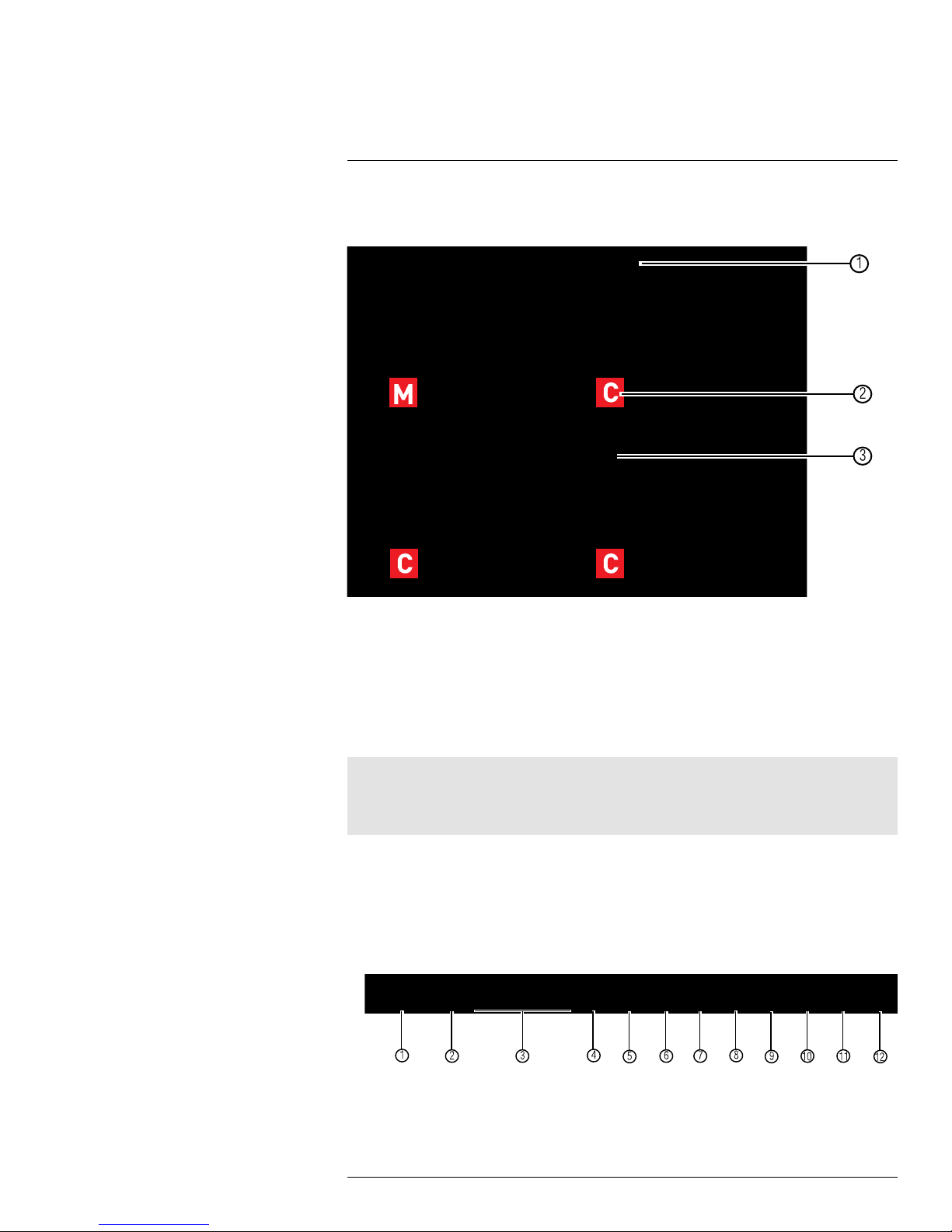
Using the On-Screen Display
Use the system’s graphical on-screen display to navigate menus and configure options
and settings.
1. Date & Time: Displays the date and time on the system
2. Record Status: Displays the current recording status of the system: C = continuous
(normal recording); M = motion recording; A = alarm recording (only available on models that have alarm/sensor support; alarm/sensor devices are required and are not
included).
3. Channel Number/Channel Title: Displays channel number or channel title. To rename the channel number to a title, see 15.1.1 Configuring Custom Channel Names,
page 40.
Note
If you can’t see your mouse cursor on screen:
Press 0 on the remote control three times to switch the mouse and system interface between VGA/HDMI
and BNC monitors.
9.1 Using the Menu Bar
The Menu Bar allows you to access the Main Menu and control basic functions of the DVR.
To access the Menu Bar:
• Right-click or move the mouse cursor to the bottom of the screen to access the Menu
Bar.
1. Main Menu: Opens the Main Menu.
2. Lock: Click to log out if a user is currently logged in.
#LX400008; r. 2.0/12067/12067; en-US
18

9
Using the On-Screen Display
3. Split Screen buttons: Select the desired split-screen mode (available options depend on the number of channels your DVR has).
4. PTZ: Opens the PTZ controls.
5. Start/Stop PTZ Cruise: Start or stop the PTZ cruise function.
6. Zoom: Opens digital zoom. Must be in Full-screen / Live Viewing Mode.
7. Record Search: Opens the DVR Search Menu. This allows you to search for video
recorded on the DVR.
8. Start/Stop Recording: Start or stop DVR recording on all channels. Password required; does not override scheduled recording.
9. Start/Stop SEQ: Start or stop Sequence Mode. In Sequence Mode, DVR automatically switches between channels every few seconds.
10. PIP 1X1: Enable Picture in Picture Mode with one camera in full screen and one in
a small window.
11. PIP 1X2: Enable Picture in Picture Mode with one camera in full screen and two in
small windows.
12. Volume: Adjust the DVR volume (audio-capable cameras required, not included).
9.2 Using the Virtual Keyboard and Mini-Keyboard
You can input numeric or text values using the on-screen virtual keyboard. You will need to
use the Virtual Keyboard when entering your User ID and Password. The Virtual Mini-Keyboard is used to input numeric values, such as the time and date.
To use the Virtual Keyboard:
1. Using the mouse, click on an option or field, such as the User ID and Password fields.
• The Virtual Keyboard opens.
• Click Shift to switch between upper and lowercase letters.
• Click
to move the cursor between letters.
• Click <— to backspace/delete.
• Click Enter to enter your selection.
• Click ESC to close the virtual keyboard.
#LX400008; r. 2.0/12067/12067; en-US
19
9
000
0
1
2
Using the On-Screen Display
To use the Virtual Mini-Keyboard:
1. Using the Mouse, click on an option or field, such as the Time or Date fields.
• The Virtual Mini-Keyboard opens.
• Click to enter your selection.
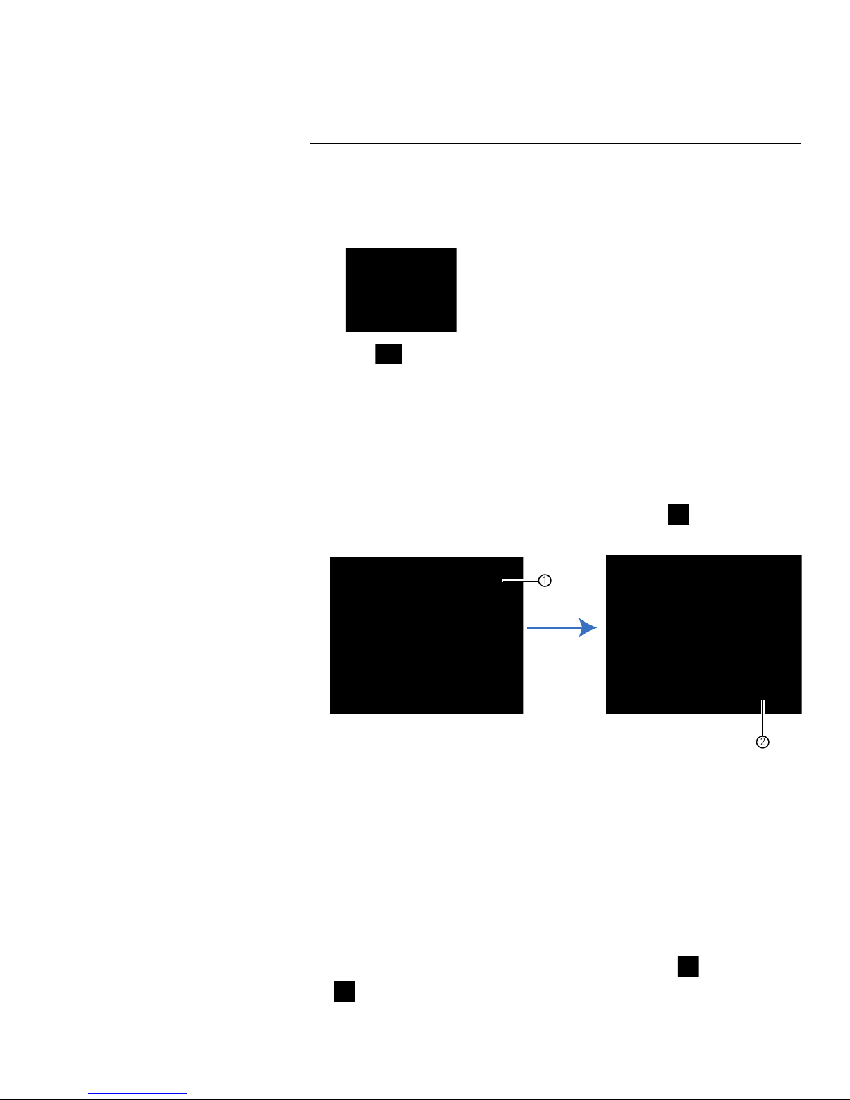
9.3 Using the Zoom Mode
Zoom Mode allows you to zoom in on an image while viewing your cameras live. This can
be useful if you want to get a closer look at a situation.
To use the Zoom Mode:
1. In Live Viewing Mode, select the channel you want to zoom in on in full-screen (double-click the channel if you are in a Split-screen View).
2. Right-click to open the Menu Bar and select the Zoom button (
). A Zoom icon ap-
pears on the screen.
2.1. Click and drag on the area of the screen you would like to enlarge. The image zooms in on the
selected area.
2.2. The box in the lower right-hand corner shows the entire camera picture with a black box around
the zoomed-in area. Click inside the box and drag to move the zoom area.
3. Right-click to exit and select a different zoom area. Right-click again to exit Zoom
Mode and return to Live Viewing Mode.
9.4 Using Picture in Picture (PIP) Mode
Picture in Picture (PIP) Mode allows you to view one channel in full-screen while viewing
up to two other channels.
To use Picture in Picture Mode:
1. Right-click to open the Menu Bar and select the PIP1X1 button (
(
). PIP1X1 shows one channel in full screen and one other channel; PIP1X2 shows
one channel in full screen and two other channels.
#LX400008; r. 2.0/12067/12067; en-US
) or PIP1X2 button
20
 Loading...