

Page 1
LORD Data Communications Protocol Manual
3DM®-CV5-10
Inertial Measurement Unit
Page 2

MicroStrain®Sensing Systems
459 Hurricane Lane
Suite 102
Williston, VT 05495
United States of America
Phone: 802-862-6629
www.microstrain.com
Copyright © 2018 LORD Corporation
3DM®, 3DM-DH®, 3DM-DH3®, 3DM-GX2®, Ask UsHow™, DEMOD-DC®, DVRT®, EmbedSense®, FAS-A®, G-Link®,
Little Sensors, Big Ideas.®, LORD Microstrain®, Live Connect™, LXRS®, MathEngine®, MicroStrain®, MIP™, MXRS®, Node
Commander®, SensorCloud™, SensorConnect™, SG-Link®, Strain Wizard®, TC-Link®, V-Link®, Wireless Simplicity,
Hardwired Reliability™, and WSDA®are trademarksof LORD Corporation.
Document 8500-0070 Revision E
Subject to change without notice.
Page 3

3DM®-CV5-10 DCP Manual
Table of Contents
1. API Introduction
2. Basic Programming
2.1 MIP Packet Overview
2.2 Command Overview
2.2.1 Example “Ping” Command Packet 9
2.2.2 Example “Ping” Reply Packet 10
2.3 Data Overview
2.3.1 Example Data Packet: 11
2.4 Example Setup Sequence
2.4.1 Continuous Data Example Command Sequence 12
2.4.2 Polling Data Example Sequence 15
2.5 Parsing Incoming Packets
2.6 Multiple Rate Data
6
7
7
9
10
11
16
17
2.7 Communications Bandwidth Management
2.7.1 UART Bandwidth Calculation 19
3. Command and Data Summary
3.1 Commands
3.1.1 Base Command Set (0x01) 21
3.1.2 3DM Command Set (0x0C) 21
3.2 Data
3.2.1 IMU Data Set (0x80) 21
4. Command Reference
4.1 Base Commands
4.1.1 Ping (0x01, 0x01) 23
4.1.2 Set To Idle (0x01, 0x02) 24
18
21
21
21
23
23
Page 4

3DM®-CV5-10 DCP Manual
4.1.3 Get Device Information (0x01, 0x03) 25
4.1.4 Get Device Descriptor Sets (0x01, 0x04) 26
4.1.5 Device Built-In Test (0x01, 0x05) 27
4.1.6 Resume (0x01, 0x06) 29
4.1.7 GPS Time Update (0x01, 0x72) 29
4.1.8 Device Reset (0x01, 0x7E) 30
4.2 3DM Commands
4.2.1 Poll IMU Data (0x0C, 0x01) 32
4.2.2 Get IMU Data Base Rate (0x0C, 0x06) 33
4.2.3 IMU Message Format (0x0C, 0x08) 34
4.2.4 Enable/Disable Continuous Data Stream (0x0C, 0x11) 36
4.2.5 Device Startup Settings (0x0C, 0x30) 38
4.2.6 Accel Bias (0x0C, 0x37) 39
4.2.7 Gyro Bias (0x0C, 0x38) 40
4.2.8 Capture Gyro Bias (0x0C, 0x39) 41
4.2.9 Coning and Sculling Enable (0x0C, 0x3E) 42
4.2.10 UART Baud Rate (0x0C, 0x40) 43
4.2.11 Advanced Low-Pass Filter Settings (0x0C, 0x50) 44
4.2.12 Device Status (0x0C, 0x64) 46
32
4.3 Error Codes
5. Data Reference
5.1 IMU Data
5.1.1 Scaled Accelerometer Vector (0x80, 0x04) 49
5.1.2 Scaled Gyro Vector (0x80, 0x05) 50
5.1.3 Delta Theta Vector (0x80, 0x07) 50
5.1.4 Delta Velocity Vector (0x80, 0x08) 51
5.1.5 GPS Correlation Timestamp (0x80, 0x12) 52
48
49
49
Page 5

3DM®-CV5-10 DCP Manual
6. MIP Packet Reference
6.1 Structure
6.2 Payload Length Range
6.3 MIP Checksum Range
6.4 16-bit Fletcher Checksum Algorithm (C Language)
7. Advanced Programming
7.1 Internal Diagnostic Functions
7.1.1 3DM-CV5-10 Internal Diagnostic Commands 54
7.2 Handling High Rate Data
7.2.1 Runaway Latency 54
7.2.2 Dropped Packets 54
7.3 Creating Fixed Data Packet Format
8. Glossary
53
53
53
53
53
54
54
54
55
56
Page 6
3DM®-CV5-10 DCP Manual
1. API Introduction
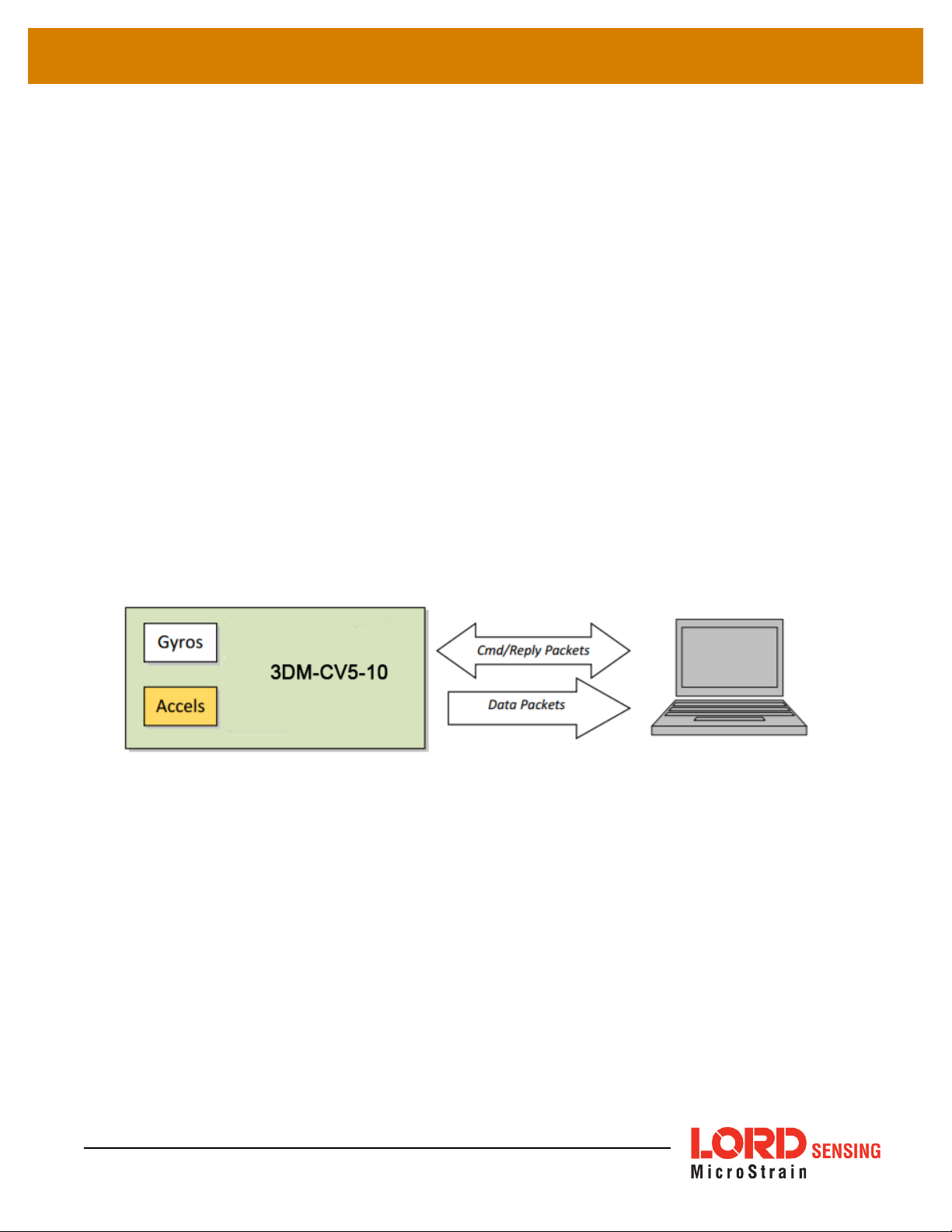
The 3DM-CV5-10 programming interface is comprised of a compact set of setup and control commands
and a very flexible user-configurable data output format. The commands and data are divided into two
command sets and one data set corresponding to the internal architecture of the device. The command
sets consist of a set of “Base” commands (a set that is common across many types of devices) and a set of
unified “3DM” (3D Motion) commands that are specific to the LORD Sensing inertial product line. The data
set represents the one type of data that the3DM-CV5-10 is capable of producing: “IMU” (Inertial
Measurement Unit) data.
Base commands Ping, Idle, Resume, Get ID Strings, etc.
3DM commands Poll IMU Data, Estimation Filter Data, etc.
The protocol is packet based. All commands, replies, and data are sent and received as fields in a
message packet. Commands are all confirmed with an ack/nack (with a few exceptions). The packets
have a descriptor type field based on their contents, so it is easy to identify if a packet contains IMU data,
commands, or replies.
IMU data Acceleration Vector, Gyro Vector, etc.
6
Page 7
3DM®-CV5-10 DCP Manual
2. Basic Programming
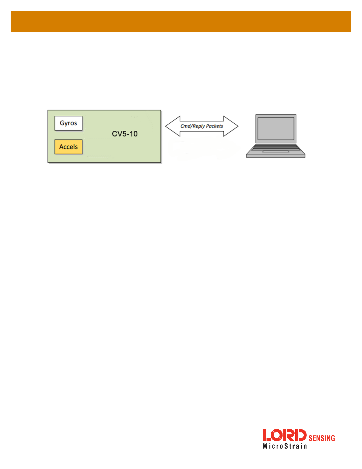
The 3DM-CV5-10 is designed to stream and IMU data packets over a common interface as efficiently as
possible. To this end, programming the device consists of a configuration stage where the data messages
and data rates are configured. The configuration stage is followed by a data streaming stage where the
program starts the incoming data packet stream.
In this section there is an overview of the packet, an overview of command and reply packets, an overview
of how an incoming data packet is constructed, and then an example setup command sequence that can
be used directly with the 3DM-CV5- 10 either through a COM utility or as a template for software
development.
2.1 MIP Packet Overview
This is an overview of the 3DM-CV5-10 packet structure. The packet structure used is the LORD “MIP”
packet. A reference to the general packet structure is presented in the MIP Packet Reference section.
An overview of the packet is presented here.
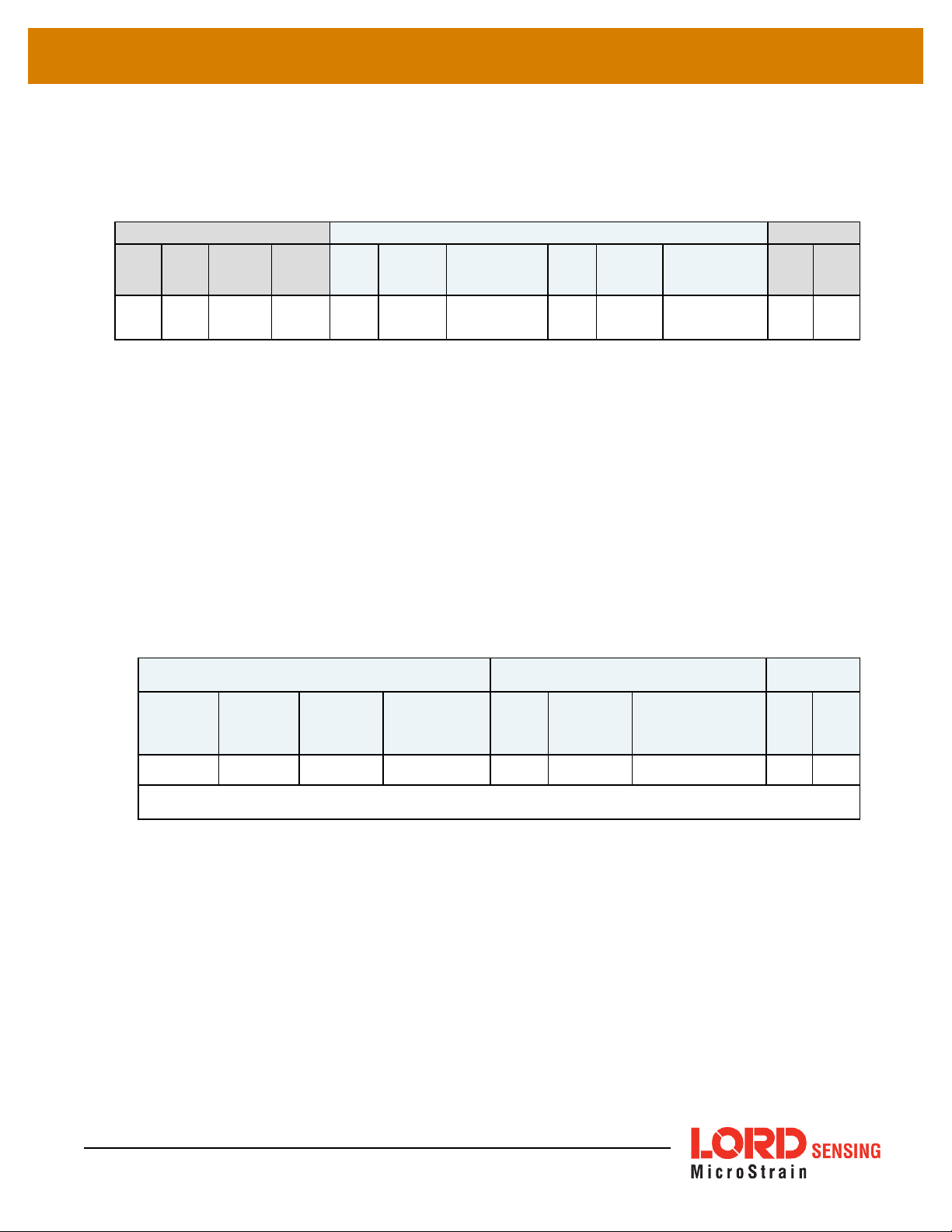
The MIP packet “wrapper” consists of a four byte header and two byte checksum footer:
7
Page 8
3DM®-CV5-10 DCP Manual
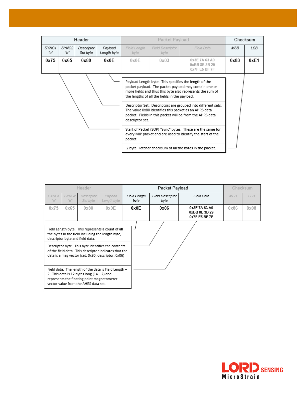
The packet payload section contains one or more fields. Fields have a length byte, descriptor byte, and
data. The diagram below shows a packet payload with a single field.
8
Page 9
3DM®-CV5-10 DCP Manual
Below is an example of a packet payload with two fields (gyro vector and mag vector). Note the
payload length byte of 0x1C which is the sum of the two field length bytes 0x0E + 0x0E:
Header Packet Payload (2 Fields) Checksum
SYNC1
SYNC2
Descriptor
“u”
0x75 0x65 0x80 0x1C 0x0E 0x05
“e”
Set byte
2.2 Command Overview
The basic command sequence begins with the host sending a command to the device. A command
packet contains a field with the command value and any command arguments.
The device responds by sending a reply packet. The reply contains at minimum an ACK/NACK field. If
any additional data is included in a reply, it appears as a second field in the packet.
Payload
Length
byte
Field 1
Length
Field 1
Descriptor
Field 1 Data
0x3E 7A 63 A0
0xBB 8E 3B 29
0x7F E5BF 7F
Field 2
Length
0x0E 0x06
Field 2
Descriptor
Field 2
Data
0x3E 7A 63 A0
0xBB 8E 3B 29
0x7F E5BF 7F
MSB LSB
0xE0 0xC6
2.2.1 Example “Ping” Command Packet
Below is an example of a “Ping” command packet from the Base command set. A “Ping” command
has no arguments. Its function is to determine if a device is present and responsive:
Header Packet Payload Checksum
SYNC1 “u SYNC2 “e”
0x75 0x65 0x01 0x02 0x02 0x01 N/A 0xE0 0x C6
Descriptor
Set byte
Payload Length
byte
Field
Byte
Length
Copy-Paste version of command: “7565 0102 0201 E0C6”
The packet header has the “ue” starting sync bytes characteristic of all MIP packets. The descriptor
set byte (0x01) identifies the payload as being from the Base command set. The length of the
payload portion is 2 bytes. The payload portion of the packet consists of one field. The field starts
with the length of the field which is followed by the descriptor byte (0x01) of the field. The field
descriptor value is the command value. Here the descriptor identifies the command as the “Ping”
command from the Base command descriptor set. There are no parameters associated with the
ping command, so the field data is empty. The checksum is a two byte Fletcher checksum (see the
MIP Packet Reference for instructions on how to compute a Fletcher two byte checksum).
Field
Descriptor
Byte
Field Data MSB LSB
9
Page 10

3DM®-CV5-10 DCP Manual
2.2.2 Example “Ping” Reply Packet
The “Ping” command will generate a reply packet from the device. The reply packet will contain an
ACK/NACK field. The ACK/NACK field contains an “echo” of the command byte plus an error code.
An error code of 0 is an “ACK” and a non-zero error code is a “NACK”:
Header Packet Payload Checksum
SYNC1 “u SYNC2 “e”
0x75 0x65 0x01 0x04 0x04 0xF1
Descriptor
Set byte
Payload Length
byte
Field
Byte
Length
Field
Descriptor
Byte
Field Data MSB LSB
Command Echo: 0x01
Error code: 0x00
0xD5 0x6A
Copy-Paste version of reply:... “7565 0104 04F1 0100 D56A”
The packet header has the “ue” starting sync bytes characteristic of all MIP packets. The descriptor
set byte (0x01) identifies the payload fields as being from the Base command set. The length of the
payload portion is 4 bytes. The payload portion of the packet consists of one field. The field starts
with the length of the field which is followed by the descriptor byte (0xF1) of the field. The field
descriptor byte identifies the reply as the “ACK/NACK” from the Base command descriptor set. The
field data consists of an “echo” of the original command (0x01) followed by the error code for the
command (0x00). In this case the error is zero, so the field represents an “ACK”. Some examples of
non-zero error codes that might be sent are “timeout”, “not implemented”, and “invalid parameter in
command”. The checksum is a two byte Fletcher checksum (see the MIP Packet Reference for
instructions on how to compute a Fletcher two byte checksum).
The ACK/NACK descriptor value (0xF1) is the same in all descriptor sets. The value belongs to a
set of reserved global descriptor values.
The reply packet may have additional fields that contain information in reply to the command. For
example, requesting Device Status will result in a reply packet that contains two fields in the packet
payload: an ACK/NACK field and a device status information field.
2.3 Data Overview
The IMU data packet is generated by the device. When the device is powered up, it may be configured
to immediately stream the data packet out to the host or it may be “idle” and waiting for a command to
either start continuous data or to get data by “polling”. Either way, the data packet is generated by the
device in the same way.
10
Page 11

3DM®-CV5-10 DCP Manual
2.3.1 Example Data Packet:
Below is an example of a MIP data packet which has one field that contains the scaled
accelerometer vector.
Header Packet Payload Checksum
SYNC1“uSYNC2
“e”
0x75 0x65 0x80 0x0E 0x0E 0x04
Descriptor
Set byte
Payload
Length byte
Field Byte
Length
Field
Descriptor
Byte
Field Data:
Accelvector (12 bytes,
3 float – X, Y, Z)
0x3E 7A 63 A0
0xBB 8E 3B 29
0x7F E5 BF 7F
MSB LSB
0x84 0xEE
Copy-Paste version: "7565 800E 0E04 3E7A 63A0 BB8E 3B29 7FE5 BF7F 84EE”
The packet header has the “ue” starting sync bytes characteristic of all MIP packets. The descriptor
set byte (0x80) identifies the payload field as being from the IMU data set. The length of the packet
payload portion is 14 bytes (0x0E). The payload portion of the packet starts with the length of the
field. "E The field descriptor byte (0x04) identifies the field data as the scaled accelerometer vector
from the IMU data descriptor set. The field data itself is three single precision floating point values of
4 bytes each (total of 12 bytes) representing the X, Y, and Z axis values of the vector. The checksum
is a two byte Fletcher checksum (see the MIP Packet Reference for instructions on how to compute
a Fletcher two byte checksum).
The format of the field data is fully and unambiguously specified by the descriptor. In this example,
the field descriptor (0x04) specifies that the field data holds an array of three single precision IEEE754 floating point numbers in big-endian byte order and that the values represent units of “g’s” and
the order of the values is X, Y, Z vector order. Any other specification would require a different
descriptor (see the Data Reference section of this manual).
Data polling commands generate two individual reply packets: An ACK/NACK packet and a data
packet. Enable/Disable continuous data commands generate an ACK/NACK packet followed by
the continuous stream of data packets.
2.4 Example Setup Sequence
Setup involves a series of command/reply pairs. The example below demonstrates actual setup
sequences that you can send directly to the 3DM-CV5-10 either programmatically or by using a COM
utility. In most cases only minor alterations will be needed to adapt these examples for your application.
11
Page 12

3DM®-CV5-10 DCP Manual
2.4.1 Continuous Data Example Command Sequence
Most applications will operate with the 3DM-CV5-10 sending a continuous data stream. To reduce
the amount of streaming data, if present during the configuration, the device is placed into the idle
state while performing the device initialization; when configuration is complete, the required data
streams are enabled to bring the device out of idle mode. Finally, the configuration is saved so that it
will be loaded on subsequent power-ups, eliminating the need to perform the configuration again.
1. Put the Device in Idle Mode
Send the "Set To Idle" command to put the device in the idle state (reply is ACK/NACK), disabling
the data-streams. This is not required but reduces the parsing burden during initialization and
makes visual confirmation of the commands easier.
MIP Packet Header Command/Reply Fields Checksum
Command:
Set to Idle
Reply:
ACK/NACK
SYNC1“uSYNC2
0x75 0x65 0x01 0x02 0x02 0x02 N/A 0xE1 0xC7
0x75 0x65 0x01 0x04 0x04 0xF1
“e”
Descriptor
Set byte
Payload
Length
Field
Length
Cmd.
Descriptor
Field Data MSB LSB
Cmd echo: 0x02
Error code: 0x 00
0xD6 0x6C
Copy-Paste version of the command: “7565 0102 0202 E1C7”
2. Configure the IMU Data-stream Format
Send a “Set IMU Message Format” command (reply is ACK/NACK). This example requests GPS
correlation timestamp, scaled gyro, and scaled accelerometer information at 100 Hz (1000Hz base
rate divided by a rate decimation of 10 on the3DM-CV5-10 = 100 Hz.) This will result in a single
IMU data packet sent at 100Hz containing the IMU GPS correlation timestamp followed by the
scaled gyro field and the scaled accelerometer field. This is a very typical configuration for a base
level of inertial data. If different rates were requested, then each packet would only contain the data
quantities that fall in the same decimation frame (see the Multiple Rate Data section). If the stream
was not disabled in the previous step, the IMU data would begin stream immediately.
12
Please note, this command will not append the requested descriptors to the current IMU datastream configuration, it will overwrite it completely.
Page 13

3DM®-CV5-10 DCP Manual
MIP Packet Header Command/Reply Fields Checksum
Command:
New IMU
Message
Format
Reply:
ACK/NACK
SYNC1“uSYNC2
0x75 0x65 0x0C 0x 0D 0x0D 0x08
0x75 0x65 0x0C 0x 04 0x04 0xF1
“e”
Descriptor
Set byte
Payload
Length
Field
Length
Cmd.
Descriptor
Field Data MSB LSB
Function: 0x 01
Desc. count: 0x03
GPS TS Desc.: 0x12
Rate Dec: 0x000A
AccelDesc.: 0x04
Rate Dec: 0x000A
Ang Rate Desc: 0x05
Rate Dec: 0x000A
Cmd echo: 0x08
Error code: 0x 00
0x45 0xF2
0xE7 0xBA
Copy-Paste version of the command: “7565 0C0D 0D08 0103 1200 0A04 000A 0500 0A45 F2”
3. Enable the IMU Data-stream
Send an Enable/Disable Continuous Stream command to enable the IMU continuous stream (reply
is ACK). This stream may have already been enabled by default; this step is to confirm they are
enabled. The stream will begin streaming data immediately.
MIP Packet Header Command/Reply Fields Checksum
SYNC1“uSYNC2
“e”
Descriptor
Set byte
Payload
Length
Field
Length
Cmd.
Desc.
Field Data MSB LSB
Command
Field 1:
Enable Continuous IMU Mes-
0x75 0x65 0x 0C 0x0A 0x 05 0x11
Func tion: 0x01
IMU: 0x 01
On: 0x01
sage
Reply Field 1:
ACK/NACK
0x75 0x65 0x 0C 0x08 0x04 0x F1
Cmd ec ho: 0x11
Error code: 0x00
Copy-Paste version of the command: “7565 0C0A 0511 0101 0105 1101 0301 24 CC”
4. Resume the Device: (Optional)
Sending the “Resume” command is another method of re-enabling transmission of enabled data
streams. If the "Resume" command is sent
before
the "Enable IMU Data Stream" command, the
13
Page 14

3DM®-CV5-10 DCP Manual
node will resume the state it was in when the "Idle" command was sent. If the "Resume" command
is sent
after
enabling the IMU Data Stream, the node will continue streaming. (reply is ACK/NACK).
MIP Packet Header Command/Reply Fields Checksum
Command:
Resume
Reply:
ACK/NACK
SYNC1“uSYNC2
“e”
0x75 0x65 0x01 0x02 0x02 0x06 N/A 0xE5 0xCB
0x75 0x65 0x01 0x04 0x04 0xF1
Descriptor
Set byte
Payload
Length
Field
Length
Copy-Paste version of the command: “7565 0102 0206 E5CB”
Cmd.
Desc.
Field Data MSB LSB
Cmd ec ho: 0x06
Error code: 0x00
0xDA 0x74
14
Page 15

3DM®-CV5-10 DCP Manual
2.4.2 Polling Data Example Sequence
Polling for data is less efficient than processing a continuous data stream, but may be more
appropriate for certain applications. The main difference from the continuous data example is the
inclusion of the Poll data commands in the data loop:
1. Put the Device in Idle Mode (Disabling the data-streams)
Same as continuous streaming (
2. Configure the IMU data-stream format
Same as continuous streaming (
3. Enable the IMU data-stream format
Same as continuous streaming (
4. Resume the Device
Returns to the state when Idle was called, except for when Enable Stream command is sent
(
see Resume the Device (Optional) on page 13
see Put the Device in Idle Mode on page 12
).
see Configure the IMU data-stream format on page 12
see Enable IMU Data-stream on page 13
).
).
).
Send Individual Data Polling Commands
Send an individual Poll IMU Data command in your data collection loop. After the ACK/NACK is
sent by the device, a single data packet will be sent according to the settings in the previous steps.
Note that the ACK/NACK has the same descriptor set value as the command, but the data packet
has the descriptor set value for the type of data (IMU or Estimation Filter):
MIP Packet Header Command/Reply Fields Checksum
Command:
Poll IMU Data
Reply Field 1:
ACK/NACK
IMUData
Packet Field 1:
Gyro Vector
IMUData
Packet Field 2:
SYNC1“uSYNC2
“e”
0x75 0x65 0x0C 0x04 0x04 0x01
0x75 0x65 0x0C 0x04 0x04 0x F1
0x75 0x65 0x80 0x1C 0x0E 0x04
Desc.
Set
Payload
Length
Field
Length
0x0E 0x 03
Cmd.
Desc.
Field Data MSB LSB
Opti on: 0x00
Desc Count: 0x00
Cmd ec ho: 0x01
Error code: 0x00
0x3E 7A 63 A0
0xBB 8E 3B 29
0x7F E5 BF 7F
0x3E 7A 63 A0
0xBB 8E 3B 29
0xEF 0xDA
0xE0 0xAC
0x41 0x BB
0xAD 0x DC
15
Page 16
3DM®-CV5-10 DCP Manual
Accel Vector
Copy-Paste version of the command: “7565 0C04 0401 0000 EFDA”
0x7F E5 BF 7F
You may specify the format of the data packet on a per-polling-command basis rather than using the
pre-set data format (see the Poll IMU Data )
The polling command has an option to suppress the ACK/NACK in order to keep the incoming
stream clear of anything except data packets. Set the option byte to 0x01 for this feature.
2.5 Parsing Incoming Packets
Setup is usually the easy part of programming the 3DM-CV5-10. Once you start continuous data
streaming, parsing and processing the incoming data packet stream will become the primary focus.
Polling for data may seem to be a logical solution to controlling the data flow, and this may be
appropriate for some applications, but if your application requires the precise delivery of inertial data, it
is often necessary to have the data stream drive the process rather than having the host try to control
the data stream through polling.
The “descriptor set” qualifier in the MIP packet header is a feature that greatly aids the management of
the incoming packet stream by making it easy to sort the packets into logical sub-streams and route
those streams to appropriate handlers. The first step is to parse the incoming character stream into
packets.
It is important to take an organized approach to parsing continuous data. The basic strategy is this:
parse the incoming stream of characters for the packet starting sequence “ue” and then wait for the
entire packet to come in based on the packet length byte which arrives after the “ue” and descriptor set
byte. Make sure you have a timeout on your wait loop in case your stream is out of sync and the starting
“ue” sequence winds up being a “ghost” sequence. If you timeout, restart the parsing with the first
character after the ghost “ue”. Once the stream is in sync, it is rare that you will hit a timeout unless you
have an unreliable communications link. After verifying the checksum, examine the “descriptor set” field
in the header of the packet. This tells you immediately how to handle the packet.
16
Page 17

3DM®-CV5-10 DCP Manual
Based on the value of the descriptor set field in the packet header, pass the packet to either a
command handler (if it is a Base command or 3DM command descriptor set) or a data handler (if it is an
IMU Filter data set). Replies to commands generally happen sequentially after a command so the
incidence of these is under program control.
For multi-threaded applications, it is often useful to use queues to buffer packets bound for different
packet handler threads. The depth of the queue can be tuned so that no packets are dropped while
waiting for their associated threads to process the packets in the queue. See Advanced Programming
Models section for more information on this topic.
Once you have sorted the different packets and sent them to the proper packet handler, the packet
handler may parse the packet payload fields and handle each of the fields as appropriate for the
application. For simple applications, it is perfectly acceptable to have a single handler for all packet
types. Likewise, it is perfectly acceptable for a single parser to handle both the packet type and the
fields in the packet. The ability to sort the packets by type is just an option that simplifies the
implementation of more sophisticated applications.
2.6 Multiple Rate Data
The IMU Message Format command allows you to set different data rates for different data quantities.
This is a very useful feature because some data, such as accelerometer and gyroscope data, usually
requires higher data rates (>100 Hz). The ability to send data at different rates reduces the parsing
load on the user program and decreases the bandwidth requirements of the communications channel.
Multiple rate data is scheduled on a common sampling rate clock. This means that if there is more than
one data rate scheduled, the schedules coincide periodically. For example, if you request
Accelerometer data at 100 Hz and Delta Theta data at 50 Hz, the Delta Theta schedule coincides with
the Accelerometer schedule 50% of the time. When the schedules coincide, then the two data
quantities are delivered in the same packet. In other words, in this example, you will receive data
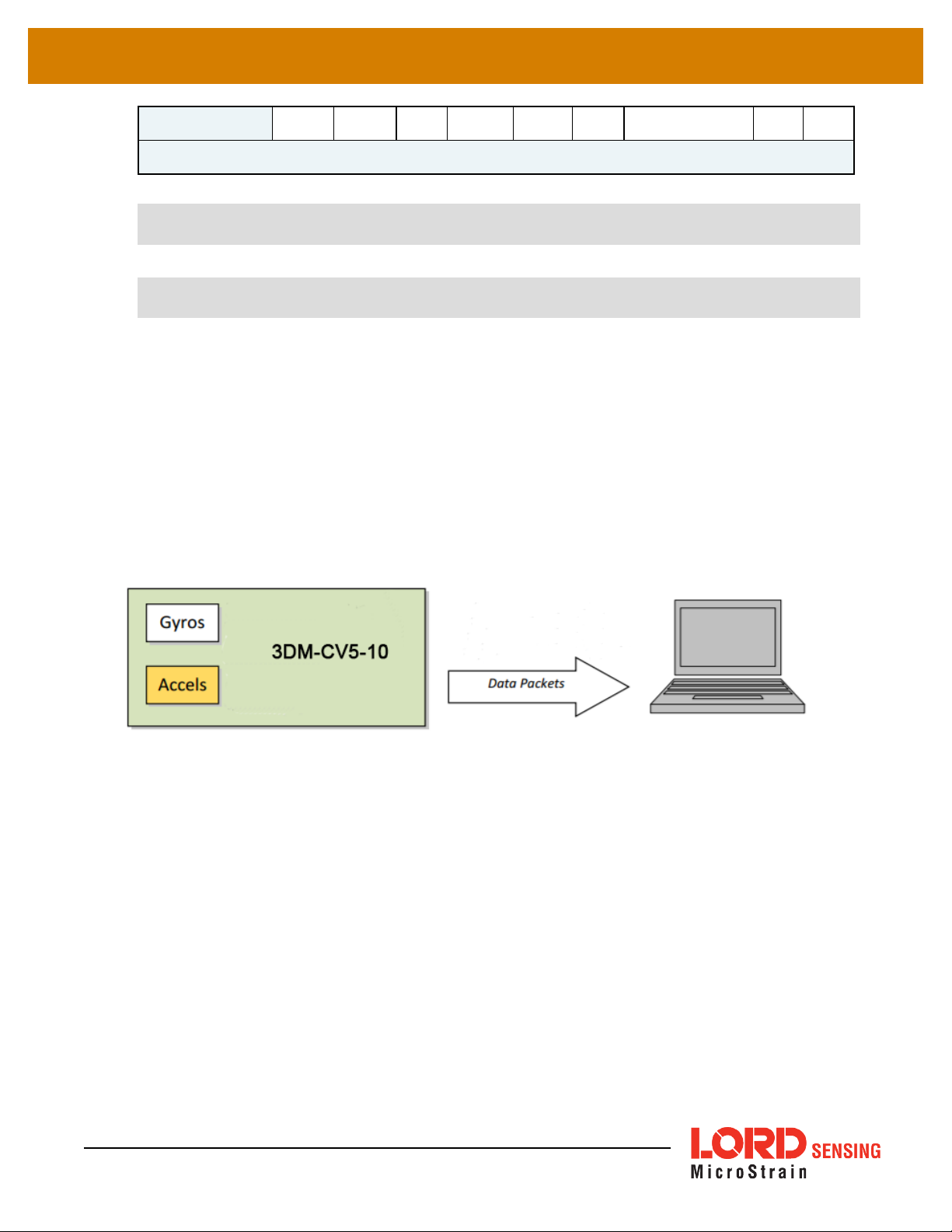
packets at 100 Hz and every packet will have an accelerometer data field and EVERY OTHER packet
will also include a Delta Theta data field:
Packet
1
Accel Accel
Packet 2
Delta
Theta
If a timestamp is included at 100 Hz, then the timestamp will also be included in every packet in this
example. It is important to note that
the timestamp.
This assures that multiple rate data is always synchronous.
Packet
3
Accel Accel
Packet 4
Delta
Theta
Packet
5
Accel Accel
Packet 6
Delta
Theta
Packet7Packet
8
Accel Accel
Delta
Theta
...
Accel
the data in a packet with a timestamp is always synchronous with
Packet 1 Packet 2 Packet 3 Packet 4 Packet 5 Packet 6 ...
17
Page 18

3DM®-CV5-10 DCP Manual
Accel
Timestamp
Accel
Delta Theta
Timestamp
Accel
Timestamp
Accel
Delta Theta
Timestamp
Accel
Timestamp
Accel
Delta Theta
Timestamp
Accel
2.7 Communications Bandwidth Management
Because of the large amount and variety of data that is available from the 3DM-CV5-10, it is quite easy
to overdrive the bandwidth of the communications channel. This can result in dropped packets. The
3DM- CV5- 10 does not do analysis of the bandwidth requirements for any given output data
configuration, it will simply drop a packet if its internal serial buffer is being filled faster than it is being
emptied. It is up to the programmer to analyze the size of the data packets requested and the available
bandwidth of the communications channel. Often the best way to determine this is empirically by trying
different settings and watching for dropped packets. Below are some guidelines on how to determine
maximum bandwidth for your application.
18
Page 19
3DM®-CV5-10 DCP Manual
2.7.1 UART Bandwidth Calculation
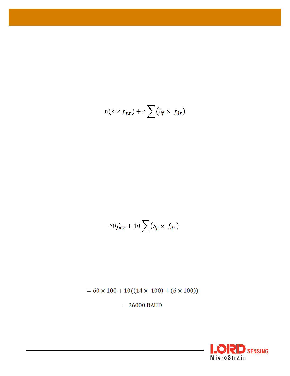
Below is an equation for the maximum theoretical UART baud rate for a given message
configuration. Although it is possible to calculate the approximate bandwidth required for a given
setup, there is no guarantee that the system can support that setup due to internal processing
delays. The best approach is to try a setting based on an initial estimate and watch for dropped
packets. If there are dropped packets, increase the baud rate, reduce the data rate, or decrease the
size or number of packets.
Where:
Sf= size of data field in bytes
fdr= field of data rate in Hz
fmr= maximum date rate in Hz
n = size of UART word = 10 bits
k = size of MIP wrapper = 6 bytes
which becomes:
Example:
For an IMU message format of Accelerometer Vector (14 byte data field) + Internal Timestamp (six
byte data field), both at 100 Hz, the theoretical minimum baud rate would be:
19
In practice, if you set the baud rate to 115200 the packets come through without any packet drops. If
you set the baud rate to the next available lower rate of 19200, which is lower than the calculated
Page 20

3DM®-CV5-10 DCP Manual
minimum, you get regular packet drops. The only way to determine a packet drop is by observing a
timestamp in sequential packets. The interval should not change from packet to packet. If it does
change then packets were dropped.
20
Page 21

3DM®-CV5-10 DCP Manual
3. Command and Data Summary
Below is a summary of the commands and data available in the programming interface. Commands and
data are denoted by two values. The first value denotes the “descriptor set” that the command or data
belongs to (Base command, 3DM command,IMU data) and the second value denotes the unique
command or data “descriptor” in that set. The pair of values constitutes a “full descriptor”.
3.1 Commands
3.1.1 Base Command Set (0x01)
Ping (0x01, 0x01)
Set to Idle (0x01, 0x02)
Get Device Information (0x01, 0x03)
Get Device Descriptor Sets (0x01, 0x04)
Device Built-In Test (BIT) (0x01, 0x05)
Resume (0x01, 0x06)
GPS Time Update (0x01, 0x72)
Device Reset (0x01, 0x7E)
3.1.2 3DM Command Set (0x0C)
Poll IMU Data (0x0C, 0x01)
Get IMU Data Rate Base (0x0C, 0x06)
IMU Message Format (0x0C, 0x08)
Enable/Disable Device Continuous Data Stream (0x0C, 0x11)
Device Startup Settings (0x0C, 0x30)
Accel Bias (0x0C, 0x37)
Gyro Bias (0x0C, 0x38)
Capture Gyro Bias (0x0C, 0x39)
Coning and Sculling Enable (0x0C, 0x3E)
Change UART Baud rate (0x0C, 0x40)
Advanced Low-Pass Filter Settings (0x0C, 0x50)
Device Status* (0x0C, 0x64)
*Advanced commands
3.2 Data
3.2.1 IMU Data Set (0x80)
Scaled Accelerometer Vector (0x80, 0x04)
Scaled Gyro Vector (0x80, 0x05)
21
Page 22

3DM®-CV5-10 DCP Manual
Delta Theta Vector (0x80, 0x07)
Delta Velocity Vector (0x80, 0x08)
GPS Correlation Timestamp (0x80, 0x12)
22
Page 23

3DM®-CV5-10 DCP Manual
4. Command Reference
4.1 Base Commands
The Base command set is common to many LORD Sensing devices. With the Base command set it is
possible to identify many properties and do basic functions on a device even if you do not recognize its
specialized functionality or data. The commands work the same way on all devices that implement this
set.
4.1.1 Ping (0x01, 0x01)
Send "Ping" command
Description
Device responds with ACK if present.
Field Format
Command
Reply:
ACK/ NACK
Field Length
0x02 0x01 N/A
0x04 0xF1
Field
Descriptor
Field Data
U8 - echo the command byte
U8 - error code (0: ACK, non-zero: NACK)
MIP Packet Header Command/Reply Fields Checksum
Example
Command:
Ping
Reply:
ACK/NACK
Sync1 Sync2
0x75 0x 65 0x01 0x 02 0x02 0x01 0xE0 0xC6
0x75 0x 65 0x01 0x 04 0x04 0xF1
Desc.
Set
Payload
Length
Field
Length
Copy-Paste version of the command: “7565 0102 0201 E0C6”
Field
Desc.
Field Data MSB LSB
Command echo: 0x01
Error code: 0x00
0xD5 0x6A
23
Page 24

3DM®-CV5-10 DCP Manual
4.1.2 Set To Idle (0x01, 0x02)
Place device into idle mode
Description
Command has no parameters. Device responds with ACK if successfully placed in idle
mode. This command will suspend streaming (if enabled) or wake the device from sleep (if
sleeping) to allow it to respond to status and setup commands. You may restore the
device mode by issuing the Resume command.
Field Format
Command
Reply :
ACK/ NACK
Field Length
0x02 0x02 N/A
0x04 0xF1
Field
Descriptor
Field Data
U8 - echo the command byte
U8 - error code (0: ACK, non-zero: NACK)
MIP Packet Header Command/Reply Fields Checksum
Example
Command:
Set to Idle
Reply:
ACK/NACK
Sync1 Sync2
0x75 0x65 0x01 0x02 0x02 0x02 0xE1 0x C7
0x75 0x65 0x01 0x04 0x04 0xF1
Desc.
Set
Payload
Length
Field
Length
Copy-Paste version of the command: “7565 0102 0202 E1C7”
Field
Desc.
Field Data MSB LSB
Command echo: 0x02
Error code: 0x00
0xD6 0x 6C
24
Page 25

3DM®-CV5-10 DCP Manual
4.1.3 Get Device Information (0x01, 0x03)
Description Get the device ID strings and firmware version.
Field Format
Command
Reply Field 1:
ACK/ NACK
Reply Field 2:
Array of
Descriptors
Example
Field Length
Field
Descriptor
Field Data
0x02 0x03 N/A
0x04 0xF1
U8 - echo the command byte
U8 - error code (0: ACK, non-zero: NACK)
Binary
Offset
Description Data Type Units
0 Firmware version U16 N/A
2 Model Name String(16) N/A
0x54 0x81
18 Model Number String(16) N/A
34 Serial Number String(16) N/A
50 Reserved String (16) N/A
66 Options String (16) N/A
MIP Packet Header Command/Reply Fields Checksum
Sync1 Sync2
Desc.
Set
Payload
Length
Field
Length
Field
Desc.
Field Data MSB LSB
Command:
Get Device Info
Reply Field 1:
ACK/NACK
Reply Field 2:
Device Info Field
0x75 0x65 0x 01 0x02 0x02 0x03 0xE2 0x C8
0x75 0x65 0x 01 0x58 0x04 0xF1
0x54 0x81
Copy-Paste version of the command: “7565 0102 0203 E2C8”
Command echo:
0x03
Error code:
0x00
FW Version: 0x05F E
0x## 0x##
25
Page 26

3DM®-CV5-10 DCP Manual
4.1.4 Get Device Descriptor Sets (0x01, 0x04)
Get the set of descriptors that this device supports
Description
Field Format
Command
Reply Field 1:
ACK/ NACK
Reply Field 2:
Array of
Descriptors
Example
Reply has two fields: “ACK/NACK” and “Descriptors”. The “Descriptors” field is an array
of 16 bit values. The MSB specifies the descriptor set and the LSB specifies the
descriptor.
Field Length
Field
Descriptor
Field Data
0x02 0x04 N/A
0x04 0xF1
<(2 x n) + 2> 0x82
U8 - echo the command byte
U8 - error code (0: ACK, non-zero: NACK)
Binary
Offset
0
2
... etc. ...
Description Data Type
MSB: Descriptor Set
U16
LSB: Descriptor
MSB: Descriptor Set
U16
LSB: Descriptor
MIP Packet Header Command/Reply Fields Checksum
Sync1 Sync2
Desc.
Set
Payload
Length
Field Length
Field
Desc.
Field Data MSB LSB
Command:
Get Device
0x75 0x 65 0x 01 0x02 0x02 0x04 0xE3 0xC9
Info
Reply Field 1:
ACK/NACK
0x75 0x 65 0x 01 0x04 0x04 0xF1
Reply Field 2:
Array of
Descriptors
Copy-Paste version of the command: “7565 0102 0204 E3C9”
26
<(2 x n) + 2> 0x82
Command echo: 0x01
Error code: 0x00
0x0101
0x0102
0x0103
…
0x0C01
0x0C02
…
nth descriptor:
0x## 0x##
Page 27

3DM®-CV5-10 DCP Manual
4.1.5 Device Built-In Test (0x01, 0x05)
Run the device Built-In Test (BIT). The Built-In Test command always returns a 32 bit
value. A value of 0 means that all tests passed. A non-zero value indicates that not all
tests passed. The failure flags are device dependent. The flags for the 3DM-CV5-10 are
defined below.
3DM-CV5-10 BIT Error Flags:
Description
Field Format
Byte
Device
Bit 1 (LSB)
Bit 2
Bit 3
Bit 4
Bit 5
Bit 6
Bit 7
Bit 8 (MSB)
Field Length
Byte 1 (LSB) Byte 2 Byte 4 (MSB)
Processor Board Sensor Board Kalman Filter
WDT Reset (Latching,
Reset after first
commanded BIT)
Reserved
Reserved
Reserved Reserved Reserved
Reserved Reserved Reserved
Reserved Reserved Reserved
Reserved Reserved Reserved
Reserved Reserved Reserved
Field
Descriptor
Field Data
IMU
Communication Fault
Magnetometer Fault
(if applicable)
Pressure Sensor Fault
(if applicable)
Solution Fault
Reserved
Reserved
Command
Reply Field 1:
ACK/ NACK
Reply Field 2:
Array of BIT
Errors
Example
Command
Built-In Test
27
0x02 0x05 N/A
0x04 0xF1
U8 - echo the command byte
U8 - error code (0: ACK, non-zero: NACK)
0x06 0x83 U32 - BIT Error Flags
MIP Packet Header Command/Reply Fields Checksum
Sync1 Sync2
0x75 0x65 0x 01 0x02 0x02 0x05 N/A 0xE4 0xCA
Desc.
Set
Payload
Length
Field
Length
Field
Desc.
Field Data MSB LSB
Page 28

3DM®-CV5-10 DCP Manual
Reply Field 1:
ACK/NACK
0x75 0x65 0x 01 0x0A 0x 04 0xF1
Reply Field 2:
BIT Error Flags
Copy-Paste version of the command: “7565 0102 0205 E4CA”
0x06 0x 83
Echo c md: 0x 05
Error code: 0x00
BIT Error Flags :
0x00000000
0x68 0x7D
28
Page 29

3DM®-CV5-10 DCP Manual
4.1.6 Resume (0x01, 0x06)
Place device back into the mode it was in before issuing the Set To Idle command.
Description
If the Set To Idle command was not issued, then the device is placed in default mode.Command has no parameters. Device responds with ACK if stream successfully
enabled.
Field Format
Command
Reply:
ACK/ NACK
Field Length
0x02 0x06 N/A
0x04 0xF1
Field
Descriptor
Field Data
U8 - echo the command byte
U8 - error code (0: ACK, non-zero: NACK)
MIP Packet Header Command/Reply Fields Checksum
Example
Command:
Resume
Reply:
ACK/NACK
Sync1 Sync2
0x75 0x65 0x01 0x02 0x02 0x 06 0xE5 0xCB
0x75 0x65 0x01 0x04 0x04 0xF 1
Desc.
Set
Payload
Length
Field
Length
Copy-Paste version of the command: “7565 0102 0206 E5CB”
Field
Desc.
Field Data MSB LSB
Command echo: 0x01
Error code: 0x00
0xDA 0x74
Description
29
4.1.7 GPS Time Update (0x01, 0x72)
This message updates the internal GPS Time as reported in the Filter Timestamp.
This command enables synchronization of the IMU Timestamp with an external GPS
receiver. When combined with a PPS input applied to pin 7 of the I/O connector, the GPS
Correlation Timestamp in the inertial data output is synchronized with the external GPS
clock. It is recommended that this update command be sent once per second. See the
GPS Correlation Timestamp command for more information.
Possible function selector values:
0x01 – Apply new settings
0x02 – Read back current settings
0x06 – Apply new settings with no ACK/NACK reply
Possible field selector values:
0x01 – GPS Week Number
Page 30

3DM®-CV5-10 DCP Manual
4.1.7 GPS Time Update (0x01, 0x72)
0x02 – GPS Seconds
Field Format
Command
Reply:
ACK/NACK
Reply Field 2
(function = 2,
selector = 1)
Reply Field 2
(function = 2,
selector = 2)
Example
Command:
GPS Time
Update
Field Length
Field
Descriptor
Field Data
U8 - Function Selector
0x08 0x72
U8 - GPS Time Field Selector
U32 - New Time Value
0x04 0xF1
U8 - echo the command descriptor
U8 - error code (0: ACK, non-zero: NACK)
0x06 0x84 U32 – Current GPS Week Value
0x06 0x85 U32 – Current GPS Seconds Value
MIP Packet Header Command/Reply Fields Checksum
Sync1 Sync2
0x75 0x65 0x 01 0x08 0x08 0x72
Desc.
Set
Payload
Length
Field
Length
Field
Desc.
Field Data MSB LSB
Fctn (Apply): 0x01
Field (Week): 0x00
Val: 0x 00000698
0xFD 0x 32
Reply :
ACK/NACK
0x75 0x65 0x 01 0x04 0x04 0xF1
Copy-Paste version of the command: “7565 0108 0872 0101 0000 0698 FD32”
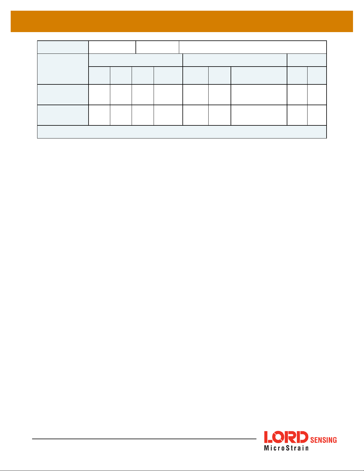
4.1.8 Device Reset (0x01, 0x7E)
Resets the device.
Description
Device responds with ACK if it recognizes the command and then immediately resets.
Field Format
Command
Reply Field 1:
30
Field Length
0x02 0x7E N/A
0x04 0xF1
Field
Descriptor
Field Data
U8 - Echo the command byte
Cmd ec ho: 0x72
Error code: 0x00
0x46 0x4C
Page 31
3DM®-CV5-10 DCP Manual
ACK/ NACK
U8 - Error code (0: ACK, non-zero: NACK)
MIP Packet Header Command/Reply Fields Checksum
Example
Command:
Ping
Reply Field 1:
ACK/NACK
Sync1 Sync2
0x75 0x65 0x01 0x 02 0x 02 0x 7E 0x5D 0x43
0x75 0x65 0x01 0x 04 0x 04 0x F1
Desc.
Set
Payload
Length
Field
Length
Copy-Paste version of the command: “7565 0102 027E 5D43”
Field
Desc.
Field Data MSB LSB
Command echo: 0x7E
Error code: 0x00
0x52 0x 64
31
Page 32

3DM®-CV5-10 DCP Manual
4.2 3DM Commands
The 3DM command set is common to the LORD Sensing Inertial sensors that support the MIP packet
protocol. Because of the unified set of commands, it is easy to migrate code from one inertial sensor to
another.
4.2.1 Poll IMU Data (0x0C, 0x01)
Poll the device for an IMU message with the specified format
This function polls for an IMU message using the provided format. The resulting message
will maintain the order of descriptors sent in the command and any unrecognized
descriptors are ignored. If the format is not provided, the device will attempt to use the
stored format (set with the Set IMU Message Format command.) If no format is provided
Description
and there is no stored format, the device will respond with a NACK. The reply packet contains an ACK/NACK field. The polled data packet is sent separately as an IMU Data
packet.
Field Format
Command
Reply:
ACK/ NACK
Example
Command:
Poll IMU data
(use stored
format)
Command:
Poll IMU data
(use specified
format)
Possible Option Selector Values:
0x00 – Normal ACK/NACK Reply.
0x01 – Suppress the ACK/NACK reply.
Field Length
Field
Descriptor
Field Data
U8 – Option Selector
4 + 3*N 0x01
U8 – Number of Descriptors (N)
N*(U8 – Descriptor, U16 Reserved)
0x04 0xF1
U8 - echo the command byte
U8 - error code (0: ACK, non-zero: NACK)
MIP Packet Header Command/Reply Fields Checksum
Sync1 Sync2
0x75 0x65 0x0C 0x 04 0x04 0x 01
0x75 0x65 0x0C 0x0A 0x0A 0x01
Desc.
Set
Payload
Length
Field
Length
Field
Desc.
Field Data MSB LSB
Opti on: 0x00
Desc count: 0x00
Opti on: 0x00
Desc count: 0x02
1st Descriptor: 0x04
Reserved: 0x0000
2nd Des criptor: 0x05
Reserved: 0x0000
0xEF 0xDA
0x06 0x27
32
Page 33

3DM®-CV5-10 DCP Manual
Reply:
ACK/NACK
0x75 0x65 0x0C 0x 04 0x04 0xF1
Copy-Paste versions of the commands:
Stored format: “7565 0C04 0401 0000 EFDA”
Specified format: “7565 0C0A 0A01 0002 0400 0005 0000 0627”
4.2.2 Get IMU Data Base Rate (0x0C, 0x06)
Get the base rate for the IMU data in Hz.
Description
Field Format
Command
Reply Field 1:
ACK/ NACK
Returns the value used for data rate calculations. See the IMU Message Format com-
mand.
Field Length
Field
Descriptor
Field Data
0x02 0x06 None
0x04 0xF1
U8 - echo the command byte
U8 - error code (0: ACK, non-zero: NACK)
Command echo: 0x01
Error code: 0x00
0xE0 0xAC
Reply Field 2:
IMU Base Rate
0x04 0x83 U16 – IMU data base rate (Hz)
MIP Packet Header Command/Reply Fields Checksum
Example
Command: Get
IMU Base Rate
Reply Field 1:
ACK/NACK
Reply Field 2:
IMU Base Rate
Sync1 Sync2
0x75 0x65 0x0C 0x02 0x02 0x06 0xF0 0xF7
0x75 0x65 0x0C 0x08 0x04 0xF1
Desc.
Set
Payload
Length
Field
Length
0x04 0x83
Copy-Paste version of the command: “7565 0C02 0206 F0F7”
Field
Desc.
Field Data MSB LSB
Command echo: 0x06
Error code: 0x00
Base r ate (Hz):
0x0x 0064
0xD4 0x 6B
33
Page 34

3DM®-CV5-10 DCP Manual
4.2.3 IMU Message Format (0x0C, 0x08)
Set, read, or save the format of the IMU message packet. This command sets the format
for the IMU data packet when in standard mode. The resulting data messages will maintain the order of descriptors sent in the command. The command has a function selector
and a descriptor array as parameters.
Possible Function Selector Values:
Description
The rate decimation field is calculated as follows for IMU messages:
You should always retrieve the Base Rate from the Get IMU Data Base Rate command
for computing the desired rate decimation. Base rates vary from device to device. The
IMU base rate for the 3DM-CV5 is 500.
0x01 – Use new settings
0x02 – Read back current settings.
0x03 – Save current settings as startup settings
0x04 – Load saved startup settings
0x05 – Reset to factory default settings
Rate Decimation = IMU Base Rate / Desired Data Rate
Field Format
Command
Reply Field 1:
ACK/ NACK
Reply Field 2 :
Function = 2
Example
The device checks that all descriptors are valid prior to executing this command. If any of
the descriptors are invalid for the IMU descriptor set, a NACK will be returned and the message format will be unchanged. The descriptor array only needs to be provided if the function selector is = 1 (Use new settings). For all other functions it may be empty (Number of
Descriptors = 0).
Figure 1 -
Field Length
Field
Descriptor
Field Data
U8 – Function Selector
4 + 3*N 0x08
U8 – Number of Descriptors (N)
N*(U8 – Descriptor, U16 - Rate Decimation)
0x04 0xF1
3 + 3*N 0x80
U8 - echo the command byte
U8 - error code (0: ACK, non-zero: NACK)
U8 – Number of Descriptors (N)
N*(U8 – Descriptor, U16 - Rate Decimation)
MIP Packet Header Command/Reply Fields Checksum
Sync1 Sync2
Desc.
Set
Payload
Length
Field
Length
Field
Desc.
Field Data MSB LSB
Command:
IMU Message
34
0x75 0x65 0x0C 0x0A 0x0A 0x 08
Func tion: 0x01
Desc count: 0x02
0x22 0xA0
Page 35

3DM®-CV5-10 DCP Manual
Format (use new
settings)
1st Descriptor: 0x04
Rate Dec: 0x 000A
2nd Des criptor: 0x05
Rate Dec: 0x 000A
Reply Field :
ACK/NACK
0x75 0x65 0x0C 0x 04 0x04 0xF1
Command: IMU
Message Format
(read back cur-
0x75 0x65 0x0C 0x 04 0x04 0x08
rent settings)
Reply Field 1:
ACK/NACK
0x75 0x65 0x0C 0x0D 0x04 0x F1
Reply Field 2 :
Current IMU
Message Format
0x09 0x80
Copy-Paste version of the commands:
Use New Settings:”7565 0C0A 0A08 0102 0400 0A05 000A 22A0”
Read Current Settings: “7565 0C04 0408 0200 F8F3“
Echo c md: 0x 01
Error code: 0x00
Func tion: 0x02
Desc count: 0x00
Echo c md: 0x 08
Error code: 0x00
Desc count: 0x02
1st Descriptor: 0x03
Rate Dec: 0x 000A
2nd Des criptor: 0x04
Rate Dec: 0x 000A
0xE7 0xBA
0xF8 0x F3
0x98 0x0F
35
Page 36

3DM®-CV5-10 DCP Manual
4.2.4 Enable/Disable Continuous Data Stream (0x0C, 0x11)
Control the streaming of IMU and Estimation Filter data. If disabled, the data from the
selected device is not continuously transmitted. Upon enabling, the most current data will
be transmitted (i.e. no stale data is transmitted.) The default for the device is all streams
enabled. For all functions except 0x01 (use new setting), the new enable flag value is
ignored.
Possible function selector values:
Description
The device selector can be:
0x01 – Apply new settings
0x02 – Read back current settings
0x03 – Save current settings as startup settings
0x04 – Load saved startup settings
0x05 – Load factory default settings
Field Format
Command
Reply Field 1:
ACK/ NACK
Reply Field 2:
(function = 2)
Examples
0x01 – IMU
0x03 – Estimation Filter
The enable flag can be either:
0x00 – Disable the selected stream
0x01 – Enable the selected stream
Field Length
Field
Descriptor
Field Data
(default)
U8 – Function Selector
0x05 0x11
U8 – Device Selector
U8 - New Enable Flag
0x04 0xF1
0x04 0x85
U8 - Echo the command descriptor
U8 - Error code (0: ACK, non-zero: NACK)
U8 – Device Selector
U8 - Current Device Enable Flag
MIP Packet Header Command/Reply Fields Checksum
Sync1 Sync2
Desc.
Set
Payload
Length
Field
Length
Field
Desc.
Field Data MSB LSB
Command:
IMU Stream ON
Command:
IMU Stream
36
0x75 0x65 0x 0C 0x05 0x05 0x11
0x75 0x65 0x 0C 0x05 0x05 0x11
Func tion (Apply): 0x01
Device (IMU): 0x01
Stream (ON): 0x01
Func tion (Apply): 0x01
Device (IMU): 0x01
0x04 0x1A
0x03 0x19
Page 37

3DM®-CV5-10 DCP Manual
OFF
Reply:
ACK/NACK
0x75 0x65 0x 0C 0x04 0x04 0x F1
Copy-Paste version of the 1st command: ”7565 0C05 0511 0101 0104 1A”
Stream (OFF): 0x00
Echo c md: 0x 11
Error code: 0x00
0xF0 0x CC
37
Page 38

3DM®-CV5-10 DCP Manual
4.2.5 Device Startup Settings (0x0C, 0x30)
Read, Save, Load, or Reset to Default the values for all device settings.
Possible function selector values:
Description
Notes
Field Format
Command
Reply:
ACK/ NACK
Examples
Command:
Save All
0x03 – Save current settings as startup settings**
0x04 – Load saved startup settings
0x05 – Reset to factory default settings
**
When a save current settings command is issued a brief data disturbance may occur as
all settings are written to non-volatile memory.
Field Length
Field
Descriptor
Field Data
0x03 0x30 U8 – Function selector
0x04 0xF1
U8 - echo the command byte
U8 - error code (0: ACK, non-zero: NACK)
MIP Packet Header Command/Reply Fields Checksum
Sync1 Sync2
0x75 0x65 0x0C 0x03 0x03 0x30 Fctn (Save): 0x03 0x1F 0x45
Desc.
Set
Payload
Length
Field
Length
Field
Desc.
Field Data MSB LSB
Reply:
ACK/NACK
0x75 0x65 0x0C 0x04 0x04 0x F1
Copy-Paste version of the command: “7565 0C03 0330 031F 45”
38
Echo cmd: 0x30
Error code: 0x00
0x0F 0x 0A
Page 39

3DM®-CV5-10 DCP Manual
4.2.6 Accel Bias (0x0C, 0x37)
Set the value, or read the current value of the IMU7 Accelerometer Bias Vector. For all
functions except 0x01 and 0x06 (apply new settings), the new vector value is ignored. The
bias value is subtracted from the scaled accelerometer value prior to output.
Possible function selector values:
Description
Field Format
Command
Field Length
0x0F 0x37
0x01 - Apply new settings
0x02 – Read back current settings
0x03 – Save current settings as startup settings
0x04 – Load saved startup settings
0x05 – Load factory default settings
0x06 - Apply new settings with no ACK/NACK reply
Field
Descriptor
Advanced
Field Data
U8 – Function selector
float - X Accel Bias Value
float - Y Accel Bias Value
float - Z Accel Bias Value
Reply Field 1:
ACK/ NACK
Reply Field 2:
Function = 2
0x04 0xF1
0x0E 0x9A
U8 - echo the command byte
U8 - error code (0: ACK, non-zero: NACK)
float - Current X Accel Bias Value
float - Current Y Accel Bias Value
float - Current Z Accel Bias Value
MIP Packet Header Command/Reply Fields Checksum
Examples
Command:
Accel Bias
Reply Field :
ACK/NACK
Sync1 Sync2
0x75 0x65 0x0C 0x0F 0x0F 0x37
0x75 0x65 0x0C 0x 04 0x 04 0x F1
Desc.
Set
Payload
Length
Field
Length
Field
Desc.
Field Data MSB LSB
Fctn (Apply): 0x01
Field (Bias): 0x00000000
0x00000000
0x00000000
Echo cmd: 0x37
Error code: 0x00
Copy-Paste version of the command: "7565 0C0F 0F37 0100 0000 0000 0000 0000 0000 003C 75”
0x3C 0x75
0x16 0x18
39
Page 40

3DM®-CV5-10 DCP Manual
4.2.7 Gyro Bias (0x0C, 0x38)
Set the value, or read the current value of the IMU7 Gyro Bias Vector. For all functions
except 0x01 and 0x06 (apply new settings), the new vector value is ignored. The bias
value is subtracted from the scaled Gyro value prior to output.
Possible function selector values:
Description
Field Format
Command
Field Length
0x0F 0x38
0x01 - Apply new settings
0x02 – Read back current settings
0x03 – Save current settings as startup settings
0x04 – Load saved startup settings
0x05 – Load factory default settings
0x06 - Apply new settings with no ACK/NACK reply
Field
Descriptor
Advanced
Field Data
U8 – Function selector
float - X Gyro Bias Value
float - Y Gyro Bias Value
float - Z Gyro Bias Value
Reply Field 1:
ACK/ NACK
Reply Field 2:
Function = 2
0x04 0xF1
0x0E 0x9B
U8 - echo the command byte
U8 - error code (0: ACK, non-zero: NACK)
float - Current X Gyro Bias Value
float - Current Y Gyro Bias Value
float - Current Z Gyro Bias Value
MIP Packet Header Command/Reply Fields Checksum
Examples
Command:
Gyro Bias
Reply Field :
ACK/NACK
Sync1 Sync2
0x75 0x65 0x 0C 0x0F 0x0F 0x38
0x75 0x65 0x 0C 0x 04 0x 04 0xF1
Desc.
Set
Payload
Length
Field
Length
Field
Desc.
Field Data MSB LSB
Fctn (Apply): 0x01
Field (Bias): 0x00000000
0x00000000
0x00000000
Echo cmd: 0x38
Error code: 0x00
Copy-Paste version of the command: “7565 0C0F 0F38 0100 0000 0000 0000 0000 0000 003D 83”
0x3D 0x83
0x17 0x1A
40
Page 41

3DM®-CV5-10 DCP Manual
4.2.8 Capture Gyro Bias (0x0C, 0x39)
This command will cause the 3DM-CV5-10 to sample its sensors for the specified number
of milliseconds. The resulting data will be used to initialize its orientation, and to estimate
its gyro bias error. The estimated gyro bias error will be automatically written to the Gyro
Bias vector. The bias vector is not saved as a startup value. If you wish to save this
Description
vector, use the Gyro Bias command.
Possible sampling time values:
Total sampling time in units of milliseconds.
Range of values: 1000 to 3000.
Notes
Field Format
Command
Reply Field 1:
ACK/ NACK
Reply Field 2:
Function = 2
Examples
Command:
Capture
Gyro Bias
Reply Field
1:
ACK/NACK
Note: The 3DM-CV5-10 must be stationary during the execution of the Capture Gyro Bias
operation.
Field Length
Field
Descriptor
Field Data
0x04 0x39 U16 – Sampling Time (milliseconds)
0x04 0xF1
U8 - echo the command byte
U8 - error code (0: ACK, non-zero: NACK)
float - Current X Gyro Bias Value
0x0E 0x9B
float - Current Y Gyro Bias Value
float - Current Z Gyro Bias Value
MIP Packet Header Command/Reply Fields Checksum
Sync1 Sync2
0x75 0x65 0x0C 0x04 0x 04 0x39 Sampling Time: 0x2710 0x5E 0xE0
0x75 0x65 0x0C 0x04 0x 04 0x F1
Desc.
Set
Payload
Length
Field
Length
Field
Desc.
Field Data MSB LSB
Echo cmd: 0x39
Error code: 0x00
Reply Field
2: Bias
0x0E 0x 9B
Vector
Copy-Paste version of the command: “7565 0C04 0439 2710 5EE0”
41
Field (Bias): 0x00000000
0x00000000
0x00000000
0xCF 0x19
Page 42

3DM®-CV5-10 DCP Manual
4.2.9 Coning and Sculling Enable (0x0C, 0x3E)
Set, read, or save the Coning and Sculling Compensation Enable. This function sets the
Coning and Sculling Compensation Enable. For all functions except 0x01 (use new setting), the new parameter values are ignored.
Possible function selector values:
Description
The enable flag can be either:
0x01 - Apply new settings
0x02 – Read back current settings
0x03 – Save current settings as startup settings
0x04 – Load saved startup settings
0x05 – Load factory default settings
0x00 – Disable the Coning and Sculling compensation
0x01 – Enable the Coning and Sculling compensation (default)
Field Format
Command
Reply Field 1:
ACK/ NACK
Reply Field 2:
Function = 2
Field Length
0x10 0x3E
0x04 0xF1
0x03 0x9E U8 - Current Coning and Sculling enable setting
Field
Descriptor
Field Data
U8 – Function selector
U8 - New Coning and Sculling enable setting
U8 - echo the command descriptor
U8 - error code (0: ACK, non-zero: NACK)
MIP Packet Header Command/Reply Fields Checksum
Examples
Command:
Enable Settings
Reply Field :
ACK/NACK
Sync1 Sync2
0x75 0x65 0x0C 0x04 0x04 0x3E
0x75 0x65 0x0C 0x04 0x04 0xF1
Desc.
Set
Payload
Length
Field
Length
Copy-Paste version of the command: “7565 0C04 043E 0101 2E94”
Field
Desc.
Field Data MSB LSB
Fctn (Apply): 0x01
Enable: 0x01
Echo cmd: 0x38
Error code: 0x00
0x2E 0x94
0x1D 0x26
42
Page 43
3DM®-CV5-10 DCP Manual
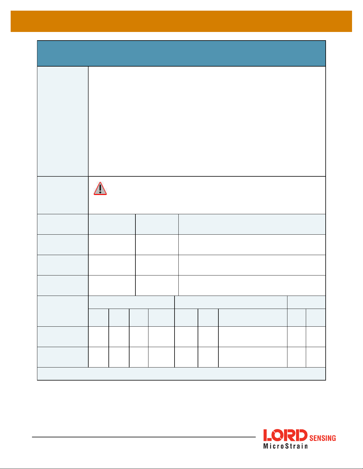
4.2.10 UART Baud Rate (0x0C, 0x40)
Change, read, or save the baud rate of the main communication channel (UART1). For all
functions except 0x01 (use new settings), the new baud rate value is ignored.
Possible function selector values:
Description
Supported baud rates are:
0x01 - Apply new settings
0x02 – Read back current settings
0x03 – Save current settings as startup settings
0x04 – Load saved startup settings
0x05 – Reset to factory default settings
Notes
Field Format
Command
Reply Field 1:
ACK/ NACK
Reply Field 2:
Function = 2
Examples
Command:
Set Baud Rate
9600, 19200, 115200
(default),
230400, 460800, 921600
The ACK/NACK packet is sent at the current baud rate and then there is a 0.25
second delay before the device will respond to commands at the new BAUD rate.
Field Length
0x07 0x40
0x04 0xF1
Field
Descriptor
Field Data
U8 – Function selector
U32 - New baud rate
U8 - Echo the command descriptor
U8 - Error code (0: ACK, non-zero: NACK)
0x06 0x87 U32 - Current baud rate
MIP Packet Header Command/Reply Fields Checksum
Sync1 Sync2
0x75 0x65 0x 0C 0x07 0x 07 0x40
Desc.
Set
Payload
Length
Field
Length
Field
Desc.
Field Data MSB LSB
Fctn (USE): 0x01
Baud (115200): 0x0001C200
0xF8 0xDA
Reply Field :
ACK/NACK
0x75 0x65 0x 0C 0x04 0x 04 0xF1
Copy-Paste version of the command: “7565 0C07 0740 0100 01C2 00F8 DA”
43
Echo cmd: 0x40
Error code: 0x00
0x1F 0x2A
Page 44

3DM®-CV5-10 DCP Manual
4.2.11 Advanced Low-Pass Filter Settings (0x0C, 0x50)
Advanced configuration for low-pass filter settings.
The scaled data quantities are by default filtered through a single-pole IIR low-pass filter
which is configured with a -3dB cutoff frequency of half the reporting frequency (set by
decimation factor in the IMU Message Format command) to prevent aliasing on a per data
quantity basis. This advanced configuration command allows for the cutoff frequency to
be configured independently of the data reporting frequency as well as allowing for a complete bypass of the digital low-pass filter.
Possible function selector values:
0x01 - Apply new settings
0x02 – Read back current settings
0x03 – Save current settings as startup settings
0x04 – Load saved startup settings
0x05 – Reset to factory default settings
Description
Possible data descriptors:
0x04 – Scaled accel data
0x05 – Scaled gyro data
0x06 – Scaled mag data (if applicable)
0x17 – Scaled pressure data
Possible filter enable values:
0x01 – Apply low-pass filter
0x00 – Do not apply low-pass filter
Manual filter bandwidth configuration:
0x01 – Use user specified -3 dB cutoff frequency
0x00 – Automatically configure -3 dB cutoff frequency to half reporting rate
-3 dB Cutoff Frequency:
Cutoff Frequency value specified must be no greater than 250 Hz.
**This value in a write command is ignored if Automatic Bandwidth is
selected.
Reserved Byte:
Field Format
44
This byte is reserved for internal use and should be left in the 0x00 state
Field Length
Field
Descriptor
Field Data
Page 45

3DM®-CV5-10 DCP Manual
Command
0x09 0x50
U8 – Function selector
U8 – Data Descriptor
U8 – Low-Pass Filter Enable/Disable
U8 – Manual/Auto -3 dB Cutoff Frequency Configuration
U16 – -3 dB Cutoff Frequency
U8 – Reserved Byte
Reply Field 1:
ACK/ NACK
Reply Field 2:
Function = 2
Examples
Command
Reply Field :
ACK/NACK
0x04 0xF1
U8 - echo the command descriptor
U8 - error code (0: ACK, non-zero: NACK)
U8 – Data Descriptor
U8 – Filter (0x01: Enabled, 0x00: Disabled)
0x08 0x8B
U8 – Cutoff Frequency (0x00: Auto, 0x01: Manual)
U16 – -3 dB Cutoff Frequency Hz
U8 – Reserved
MIP Packet Header Command/Reply Fields Checksum
Sync1 Sync2
0x75 0x65 0x0C 0x09 0x09 0x 50
0x75 0x65 0x0C 0x04 0x04 0xF1
Desc.
Set
Payload
Length
Field
Length
Field
Desc.
Field Data MSB LSB
Fctn (Apply): 0x01
Scaled Accel: 0x04
Enable Filter: 0x01
Automatic Cutoff
Configuration:
-3dB Cutoff
Frequency
(ignored for
automatic cutoff
configuration)
Reserved: 0x00
Echo cmd: 0x50
Error code: 0x00
0x00
0x0000
0x4C 0x6D
0x2F 0x4A
Copy-Paste version of the command: “7565 0C09 0950 0104 0100 0000 004E 80"
45
Page 46
3DM®-CV5-10 DCP Manual
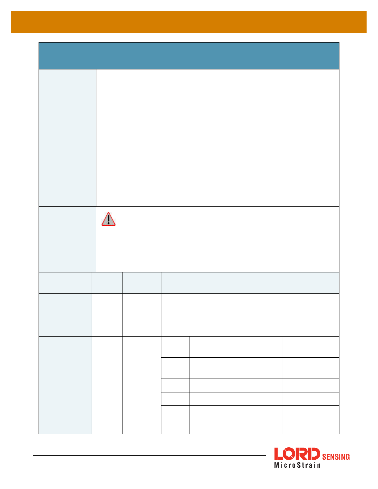
4.2.12 Device Status (0x0C, 0x64)
Description
Get the device-specific status for the 3DM-CV5-10.
Reply has two fields: “ACK/NACK” and “Device Status Field”. The device status field
may be one of two selectable formats – basic and diagnostic.
The reply data for this command is device specific. The reply is specified by two
parameters in the command. The first parameter is the model number (which for the
3DM-CV5-10 is always = 6259 (0x1873). That is followed by a status selector byte
which determines the type of data structure returned. In the case of the 3DM-CV5-10,
there are two selector values – one to return a basic status structure and a second to
return an extensive diagnostics status structure. A list of available values for the
selector values and specific fields in the data structure are as follows:
Possible Status Selector Values:
0x01 – Basic Status Structure
0x02 – Diagnostic Status Structure
Notes
Field Format
Command
Reply Field 1:
ACK/ NACK
Reply Field 2:
Basic Device
Status Field
The reply field for this command is tightly tied to the model number. Make sure
you check the model number in the reply and match it to the correct structure for the data
field for the specific device model number. This reply data descriptor 0x0C,0X90 is an
exception to the rule for MIPdescriptors that the structure of descriptor data is the same
for all devices. In this case, it is the same for all devices with the same model number
but not necessarily the same for devices with different model numbers.
Field
Length
0x02 0x64
0x04 0xF1
0x0D 0x90
Field
Descriptor
Field Data
U16-Device Model Number: set = 6259 (0x1873))
U8-Status Selector
U8 - echo the command byte
U8 - error code (0: ACK, non-zero: NACK)
Binary
Offset
0
2 Echo of the selector byte U8 N/A
3 Status Flags (Reserved) U32 N/A
Description
Echo of the Device
Model Number
Data
Type
U16 N/A
Units
Reply Field 2:
46
0x3E 0x90
7 System Timer U32 millisecond
Binary
Description
Data
Units
Page 47
3DM®-CV5-10 DCP Manual
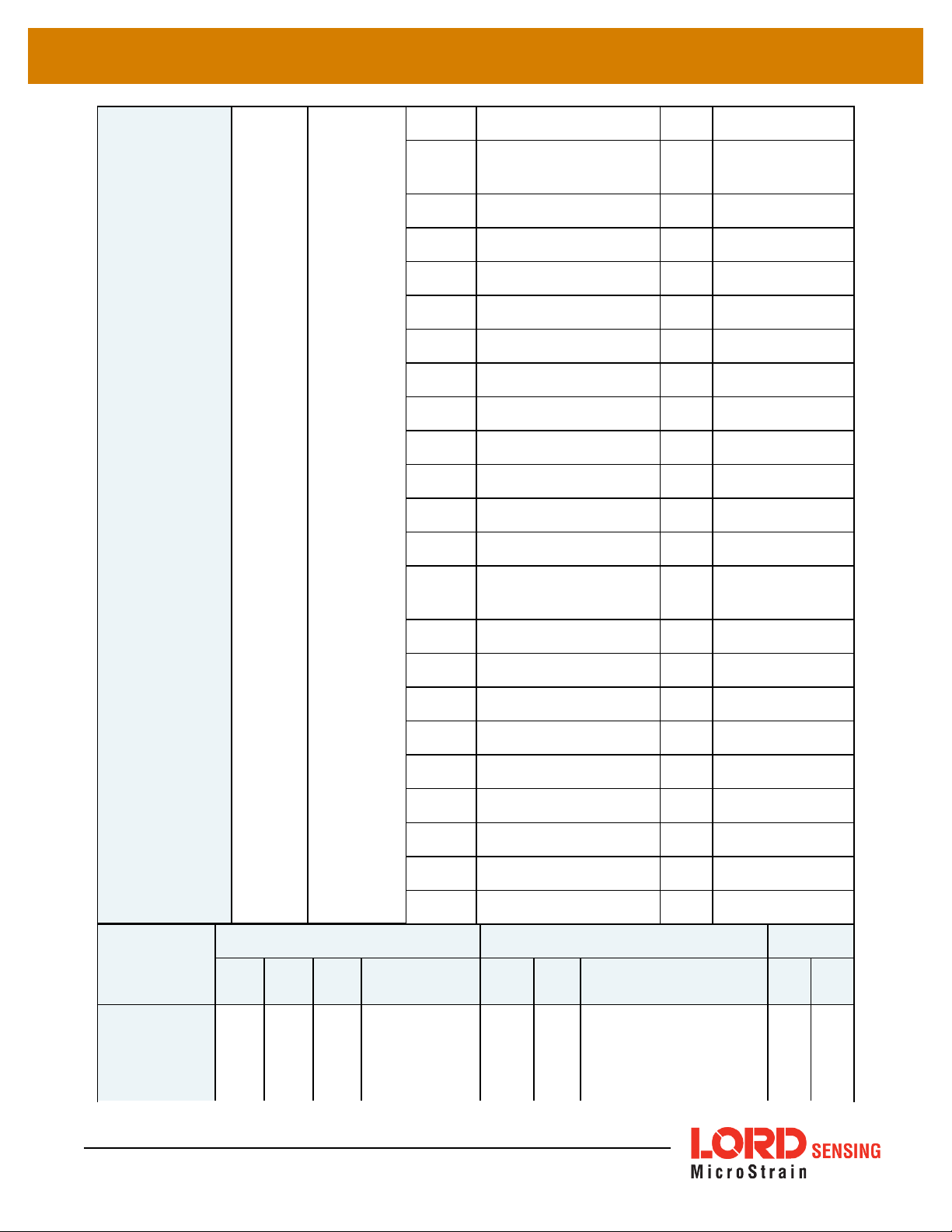
Diagnostic
Device Status
Field
Offset
0
Echo of the Device
Model Number
Type
U16 N/A
2 Echo of the selector byte U8 N/A
3 Status Flags (Reserved) U32 N/A
7 System Timer U32 millisecond
11 Has Magnetometer U8 0
12 Has Pressure U8 0
13 Power State U8 N/A
14 Gyro Range U16 degree/second
16 Accelerometer Range U16 gauss
18 Reserved U16
20 Reserved U16
22 Temperature Float degree C
Examples
Command:
Get Device
Status (return
Basic Status
26
Last temperature read
time
30 Temperature Error U8 millisecond
31 GPS PPS Triggers U32 millisecond
35 Last GPS PPS Trigger U32 millisecond
39 Stream Enabled U8 millisecond
40 Dropped Packets U32 millisecond
44 Comm bytes written U32 millisecond
48 Comm bytes read U32 millisecond
52 Comm write overruns U32 millisecond
56 Comm read overruns U32 millisecond
MIP Packet Header Command/Reply Fields Checksum
Sync1 Sync2
0x75 0x 65 0x0C 0x 05 0x05 0x64
Desc.
Set
Payload Length
Field
Length
Field
Desc.
U32 millisecond
Field Data MSB LSB
Model # (6259): 0x1873
Status selector
(basic status):
0x01
47
Page 48

3DM®-CV5-10 DCP Manual
structure:
selector = 1)
Reply Field 1:
ACK/NACK
Reply Field 2:
Device Status
(Basic Status
0x75 0x 65 0x0C 0x 15 0x04 0xF1
Echo Model # (6259): 0x 1873
0x0F 0x90
Echo cmd: 0x64
Error code: 0x00
Echo selector: 0x 01
Additonal data: ...
0x## 0x##
structure)
4.3 Error Codes
Error Name Error Value Description
MIP Unknown Command 0x01 The command descriptor is not supported by this device
MIP Invalid Checksum 0x02 An otherwise complete packet has a bad checksum
One or more parameters in the packet are invalid. This can refer to a value
MIP Invalid Parameter 0x03
MIP Command Failed 0x04 Device could not complete the command
MIP Command Timeout 0x05 Device could not complete the command within the expected time
that is outside the allowed range for a command or a value that is not the
expected size or type
48
Page 49

3DM®-CV5-10 DCP Manual
5. Data Reference
5.1 IMU Data
5.1.1 Scaled Accelerometer Vector (0x80, 0x04)
Description Scaled Accelerometer Vector
This is a vector quantifying the direction and magnitude of the acceleration that the
Notes
3DM-CV5-10 is exposed to. This quantity is fully temperature compensated and
scaled into physical units of g (1 g = 9.80665 m/sec^2). It is expressed in terms of
the 3DM-CV5-10’s local coordinate system.
Field Format
Field Length
14 (0x0E) 0x04
Data
Descriptor
Message Data
Binary Offset
0 X Accel float g
4 Y Accel float g
8 Z Accel float g
Description Data Type Units
49
Page 50

3DM®-CV5-10 DCP Manual
5.1.2 Scaled Gyro Vector (0x80, 0x05)
Description Scaled Gyro Vector
This is a vector quantifying the rate of rotation (angular rate) of the 3DM-CV5-10.
Notes
This quantity is fully temperature compensated and scaled into units of radians/second. It is expressed in terms of the 3DM-CV5-10’s local coordinate system.
Field
Length
Data
Descriptor
Message Data
Binary
Offset
Field Format
14 (0x0E) 0x05
0 X Gyro float Radians/second
4 Y Gyro float Radians/second
8 Z Gyro float Radians/second
5.1.3 Delta Theta Vector (0x80, 0x07)
Description Time integral of angular rate.
This is a vector which gives the time integral of angular rate over the interval set by
Notes
the IMU message format command. It is expressed in terms of the 3DM-CV5-10’s
local coordinate system in units of radians.
Field Length
Data
Descriptor
Description Data Type Units
Message Data
Field Format
50
14 (0x0E) 0x07
Binary
Offset
0 X Delta Theta float radians
4 Y Delta Theta float radians
8 Z Delta Theta float radians
Description Data Type Units
Page 51

3DM®-CV5-10 DCP Manual
5.1.4 Delta Velocity Vector (0x80, 0x08)
Description Time integral of acceleration.
This is a vector which gives the time integral of specific acceleration over the interval
set by the IMU message format command. It is expressed in terms of the 3DM-
Notes
CV5-10’s local coordinate system in units of g*second where g is the standard gravitational constant. To convert Delta Velocity into the more conventional units of
m/sec, simply multiply by the standard gravitational constant, 9.80665 m/sec2.
Field Format
Field Length
14 (0x0E) 0x08
Data
Descriptor
Message Data
Binary
Offset
0 X Delta Velocity float g*seconds
4 Y Delta Velocity float g*seconds
8 Z Delta Velocity float g*seconds
Description Data Type Units
51
Page 52

3DM®-CV5-10 DCP Manual
5.1.5 GPS Correlation Timestamp (0x80, 0x12)
Description GPS correlation timestamp.
This timestamp has three fields:
Timestamp Status Flags:
Double GPS TOW
U16 GPS Week number
U16 Timestamp flags
Bit0 – PPS Beacon Good If set, PPS signal is present
Bit1 – GPS Time Refresh (toggles with each refresh)
Bit2 – GPS Time Initialized (set with the first GPS Time Refresh) (
GPS Time Update (0x01, 0x72) on page 29
)
See
Notes
Field Format
This timestamp is formatted to match standard universal GPS Time format. It may
be initialized with the GPS Time Update message. If a user-supplied PPS hardware
signal is available, that, along with the user-supplied GPS Time Update message
may be used to provide precise time synchronization with other parts of the user's
system.
The GPS Time Initialized flag will only be asserted after an initial GPS Time Update
message has been received.
The “PPS Beacon Good” flag in the Timestamp flags byte indicates if the PPS
beacon coming from the GPS is present. If this flag is not asserted, it means that the
IMU internal clock is being used for the PPS. The fractional portion of the GPS
TOW represents the amount of time that has elapsed from the last PPS.
Field Length
14 (0x0E) 0x12
Data
Descriptor
Message Data
Binary
Offset
0
8
Description Data Type Units
GPS Time of
Week
GPS Week
Number
Double Seconds
U16 N/A
52
10
Timestamp
Flags
U16 See Notes
Page 53

3DM®-CV5-10 DCP Manual
6. MIP Packet Reference
6.1 Structure
Commands and Data are sent and received as fields in the LORD “MIP” packet format. Below is the
general definition of the structure:
The packet always begins with the start-of-packet sequence “ue” (0x75, 0x65). The “Descriptor Set”
byte in the header specifies which command or data set is contained in fields of the packet. The
payload length byte specifies the sum of all the field length bytes in the payload section.
6.2 Payload Length Range
The payload section can be empty or can contain one or more fields. Each field has a length byte and a
descriptor byte. The field length byte specifies the length of the entire field including the field length byte
and field descriptor byte. The descriptor byte specifies the command or data that is contained in the
field data. The descriptor can only be from the set of descriptors specified by the descriptor set byte in
the header. The field data can be anything but is always rigidly defined. The definition of a descriptor is
fundamentally described in a “.h” file that corresponds to the descriptor set that the descriptor belongs
to.
LORD Sensing provides a “Packet Builder” functionality in the “MIP Monitor” software utility to simplify
the construction of a MIP packet. Most commands will have a single field in the packet, but multiple field
packets are possible. Extensive examples complete with checksums are given in the command
reference section.
6.3 MIP Checksum Range
The checksum is a 2 byte Fletcher checksum and encompasses all the bytes in the packet:
6.4 16-bit Fletcher Checksum Algorithm (C Language)
for(i=0; i<checksum_range; i++)
{
checksum_byte1 += mip_packet[i];
checksum_byte2 += checksum_byte1;
}
53
checksum = ((u16) checksum_byte1 << 8) + (u16) checksum_byte2;
Page 54

3DM®-CV5-10 DCP Manual
7. Advanced Programming
7.1 Internal Diagnostic Functions
The 3DM-CV5- 10 supports two device specific internal functions used for diagnostics and system
status. These are Device Built In Test and Device Status. These commands are defined generically but
the implementation is very specific to the hardware implemented on this device. Other LORD Sensing
devices will have their own implementations of these functions depending on the internal hardware of
the devices.
7.1.1 3DM-CV5-10 Internal Diagnostic Commands
l Device Built In Test (0x01, 0x05)
l Device Status (0x0C, 0x64)
7.2 Handling High Rate Data
The size of the data fields from an inertial device is substantially greater than on most other types of
sensors. On top of that, in many applications it is desirable to receive that data with the lowest latency
possible and thus the highest baud rate is selected. The result is that the port servicing requirements in
terms of both speed and buffer size can be surprisingly large for inertial data. This can lead to a couple
of common problems: runaway latency and dropped packets.
7.2.1 Runaway Latency
Most operating systems provide drivers that have ample buffers and take care of port servicing at
the hardware level. Dropping packets or losing data is not usually an issue on these systems. What
can be an issue is latency, that is, when the buffer is not emptied by the application in a timely
manner. In the worst case, the buffer is being filled faster than it is emptied and the application
operates with increasingly “old” data – which causes runaway latency. It is important to monitor the
incoming data buffer to make sure you do not reach this condition.
7.2.2 Dropped Packets
Many applications do not use an operating system but are written from scratch or on top of
proprietary application frameworks. These are most often embedded MCUs or small single board
microcontrollers. On these systems, port handling is usually done in code at the hardware level.
Collecting data from a port requires the use one of three techniques: register polling, hardware
interrupts, or direct memory access (DMA). Register polling is very easy to do and is adequate for
simple communications where data comes in very small chunks and at reasonable data rates. The
problem with register polling is that you either waste time looping while waiting for a byte to come in
at the port or you get too busy doing other tasks so that by the time you poll the port, the byte is lost
54
Page 55

3DM®-CV5-10 DCP Manual
because the next one overwrites it. This causes dropped packets. On these systems, it is imperative
to utilize either a hardware interrupt or hardware DMA on the UART receiving data from the 3DMCV5- 10. The DMA or UART interrupt service routine only takes processor time when a byte is
ready and as long as the interrupts are preemptive, the processor will fetch every byte received.
Using the interrupt routine to fill a ring buffer makes the most efficient use of an MCU and makes it
easier to write your application main line code. This is essentially what drivers in operating systems
do.
7.3 Creating Fixed Data Packet Format
The MIP packet structure and protocol provides a great deal of flexibility to the user for creating a
custom data stream. It does this by allowing selectable data fields and individual data rates for each
field. The side effect of this feature is that packets vary in size depending on what data is being
delivered in any particular time frame. For example, if acceleration data is configured for 100 Hz and
gyroscope data is configured for 25 Hz, every fourth packet is larger than the previous three because of
the additional magnetometer data. In some applications, this is undesirable and there may be a
requirement for a fixed packet structure so that each data packet is exactly the same. A fixed packet
structure allows you to find data fields by fixed offsets rather than parsing the packet for each field.
A fixed packet structure is easily achieved with MIP packet protocol by simply making sure the data rate
for each data quantity is the same. The order of the data fields in the packet reflect the order of the
fields in the Message Format command and thus are completely under the control of the user. Once an
acceptable data packet structure is determined, and all the rates are set to the same decimation, use
the “Save current settings as startup settings” function selector in the message format command, and
that format will be saved and used automatically on subsequent device startups.
55
Page 56

3DM®-CV5-10 DCP Manual
8. Glossary
A
A/D Value
The digital representation of analog voltages in an analog-to-digital (A/D) conversion. The accuracy of
the conversion is dependent on the resolution of the system electronics. Higher resolution produces a
more accurate conversion.
Acceleration
In physics,acceleration is the change in the rate of speed (velocity) of an object over time.
Accelerometer
A sensor used to detect and measure magnitute and direction of an acceleration force (g-force) in reference to its sensing frame. For example, at rest perpendicular to the Earth's surface an accelerometer
will measure 9.8 meters/second squared as a result of gravity. If the device is tilted the acceleration
force will change slightly, indicating tilt of the device. When the accelerometer is moving it will measure
the dynamic force (including gravity).
Adaptive Kalman Filter (AKF)
A type of Extended Kalman Filter (EKF) that contains an optimization algorithm that adapts to dynamic
conditions with a high dependency on adaptive technology. Adaptive technology refers to the ability of
a filter to selectively trust a given measurement more or less based on a trust threshold when compared to another measurement that is used as a reference. Sensors that have estimation filters that
rely on adaptive control elements to improve their estimations are refered to as an AKF.
AHRS (Attitude and Heading Reference System)
A navigation device consisting of sensors on the three primary axes used to measure vehicle direction
and orientation in space. The sensor measurementsare typically processed by an onboard algorthim,
such as an Estimation Filter, to produce a standardized output of attitude and heading.
Algorithm
In math and science, an algorithm is a step-by-step process used for calculations.
Altitude
the distance an object is above the sea level
Angular rate
The rate of speed of which an object is rotating. Also know as angular frequency, angular speed, or
radial frequency. It is typically measured in radians/second.
API (Applications Programming Interface)
A library and/or template for a computer program that specifies how components will work together to
form a user application: for example, how hardware will be accessed and what data structures and variables will be used.
56
Page 57

3DM®-CV5-10 DCP Manual
ASTM (Association of Standards and Testing)
a nationally accepted organization for the testing and calibration of technological devices
Attitude
the orientaion of an object in space with reference to a defined frame, such as the North-East-Down
(NED) frame
Azimuth
A horizontal arc measured between a fixed point (such as true north) and the vertical circle passing
through the center of an object
B
Bias
A non-zero output signal of a sensor when no load is applied to it, typically due to sensor imperfections.
It is also called offset.
C
Calibration
to standardize a measurement by determining the deviation standard and applying a correction, or calibration, factor
Complementary Filter (CF)
A term commonly used for an algorithm that combines the readings from multiple sensors to produce a
solution. These filters typically contain simple filtering elements to smooth out the effects of sensor
over-ranging or anomalies in the magnetic field.
Configuration
A general term applied to the sensor indicating how it is set up for data acquisition. It includes settings
such as sampling rate, active measurements, measurement settings, offsets, biases, and calibration
values
Convergance
when mathematical computations approach a limit or a solution that is stable and optimal.
D
Data Acquisition
the process of collecting data from sensors and other devices
Data Logging
the process of saving acquired data to the system memory, either locally on the device, or remotely on
the host computer
Data rate
the rate at which sampled data is transmitted to the host
57
Page 58

3DM®-CV5-10 DCP Manual
Delta-Theta
the time integral of angular rate expressed with refernce to the device local coordinate system, in units
of radians
Delta-velocity
the time integral of velocity expressed with refernce to the device local coordinate system, in units of
g*second where g is the standard gravitational constant
E
ECEF (Earth Centered Earth Fixed)
a reference frame that is fixed to the earth at the center of the earth and turning about earth's axis in the
same way as the earth
Estimation Filter
A mathematical algorithm that produces a statistically optimum solution using measurements and references from multiple sources. Best known estimation filters are the Kalman Filter, Adaptive Kalman
Filter, and Extended Kalman Filter.
Euler angles
Euler angles are three angles use to describe the orientation of an object in space such as the x, y and z
or pitch; roll; and yaw. Euler angles can also represent a sequence of three elemental rotations around
the axes of a coordinate system.
Extended Kalman Filter (EKF)
Used generically to describe any estimation filter based on the Kalman Filter model that can handle
non-linear elements. Almost all inertial estimation filters are fundamentally EKFs.
G
GNSS (Global Navigation Statellite System)
a global network of space based statellites (GPS, GLONASS, BeiDou, Galileo, and others) used to triangulate position co-ordinates and provide time information for navigational purposes
GPS (Global Positioning System)
a U.S. based network of space based statellites used to triangulate position co-ordinates and provide
time information for navigational purposes
Gyroscope
a device used to sense angular movements such as rotation
H
Heading
an object's direction of travel with reference to a co-ordinate frame, such as lattitude and longitude
58
Page 59

3DM®-CV5-10 DCP Manual
Host (computer)
The host computer is the computer that orchestrates command and control of attached devices or networks.
I
IMU
Inertial Measurement System
Inclinometer
device used to measure tilt, or tilt and roll
Inertial
pertaining to systems that have inertia or are used to measure changes in inertia as in angular or linear
accelerations
INS (Inertial Navigation System)
systems that use inertial measurements exclusively to determine position, velocity, and attitude, given
an initial reference
K
Kalman Filter
a linear quadratic estimation algorithm that processes sensor data or other input data over time, factoring in underlying noise profiles by linearizing the current mean and covariance to produces an estimate
of a system’s current state that is statistically more precise than what a single measurement could produce
L
LOS (Line of Sight)
Describes the ideal condition between transmitting and receiving devices in a wireless network. As
stated, it means they are in view of each other with no obstructions.
M
Magnetometer
A type of sensor that measures the strength and direction of the local magnetic field with refernce to the
sensor frame. The magnetic field measured will be a combination of the earth's magnetic field and any
magnetic field created by nearby objects.
MEMS (Micro-Electro-Mechanical System)
The technology of miniaturized devices typically made using micro fabrication techniques such as nanotechnology. The devices range in size from one micron to several millimeters and may include very
complex electromechanical parts.
59
Page 60

3DM®-CV5-10 DCP Manual
N
NED (North-East-Down)
A geographic reference system
O
OEM
acronym for Original Equipment Manufacturer
Offset
A non-zero output signal of a sensor when no load is applied to it, typically due to sensor imperfections.
Also called bias.
Orientation
The orientaion of an object in space with reference to a defined frame. Also called attitude.
P
Pitch
In navigation pitch is what occurs when vertical force is applied at a distance forward or aft from the center of gravity of the platform, causing it to move up or down with respect to the sensor or platform frame
origin.
Position
The spatial location of an object
PVA
acronym for Position, Velocity, Attitude
Q
Quaternion
Mathematical notation for representing orientation and rotation of objects in three dimensions with
respect to the fixed earth coordinate quaternion. Quaternions convert the axis–angle representation of
the object into four numbers and to apply the corresponding rotation to a position vector representing a
point relative to the origin.
R
Resolution
In digital systems, the resolution is the number of bits or values available to represent analog voltages
or information. For example, a 12-bit system has 4096 bits of resolution and a 16-bit system has 65536
bits.
60
Page 61

3DM®-CV5-10 DCP Manual
RMS
acronym for Root Mean Squared
Roll
In navigation roll is what occurs when a horizontal force is applied at a distance right or left from the center of gravity of the platform, causing it to move side to side with respect to the sensor or platform frame
origin.
RPY
acronym for Roll, Pitch, Yaw
RS232
a serial data communications protocol
RS422
a serial data communications protocol
S
Sampling
the process of taking measurements from a sensor or device
Sampling rate
rate at which the sensors are sampled
Sampling Rate
the frequency of sampling
Sensor
a device that physically or chemically reacts to environmental forces and conditions and produces a predictable electrical signal as a result
Sigma
In statistics, sigma is the standard deviation from the mean of a data set.
Space Vehicle Information
refers to GPS satellites
Streaming
typically when a device is sending data at a specified data rate continuously without requiring a prompt
from the host
U
USB (Universal Serial Bus)
A serial data communications protocol
61
Page 62

3DM®-CV5-10 DCP Manual
UTC (Coordinated Universal Time)
The primary time standard for world clocks and time. It is similar to Greenwich Mean Time (GMT).
V
Vector
a measurement with direction and magnitude with refernce from one point in space to another
Velocity
The rate of change of position with respect to time. Also called speed.
W
WAAS (Wide Area Augmentation System)
An air navigation aid developed to allow aircraft to rely on GPS for all phases of flight, including precision approaches to any airport.
WGS (World Geodetic System)
a protocol for geo-referencing such as WGS-84
Y
Yaw
In navigation yaw is what occurs when rotational force is applied at a distance forward or aft from the
center of gravity of the platform, causing it to move around the center axis of a sensor or platform frame
origin.
62
 Loading...