

Page 1

Artwork and Signature File for:
MAN-00745, “MNL, SEL INSTALLATION AND H/W MAINTENANCE”
Artwork consists of:
• Two hundred and thirty-four (234) 8 ½ inch x 11 inch pages.
REV AUTHORED BY DATE
J. SHARP 1/8/08
REV DRAFTED BY DATE
B. MOSES 1/8/08
PROPRIETARY INFORMATION:
The content of this document is the
exclusive property of Lorad and may
not, without prior written permission
of Lorad, be reproduced, copied or
used for any purpose whatsoever.
DANBURY, CT 06810
TITLE DOCUMENT NUMBER REV
AW, MNL, SEL INSTALLATION
AND H/W MAINTENANCE
ARTWORK SIZE A SHEET 1 OF 1
AW-01859 002
ENG-0034-T33, Rev. 001
Page 2

Page 3

Page 4

Page 5

Service Support:
USA: 877-371-4372
Europe: +32.2.711.4690
All Other: 781-999-7750
© Copyright Hologic 2008. All rights reserved. Printed in USA. This manual was originally written in English.
Hologic and the Hologic Logo are registered trademarks of Hologic, Inc. Other trademarks registered or used by Hologic and its divisions and subsidiaries in the United States and
other countries include: Affinity, Affinity Platinum, Auto Film ID, “Clarity of Vision,” Dataport, HTC, LORAD, “LORAD A Hologic Company,” LORAD DSM, LORAD Elite, M-IV, M-IV
Platinum, MultiCare, Permagrid, ScoutMarc, SecurLook, SecurView, SecurView DX, SecurView RT, Selenia, SmartWindow, StereoLoc, and TechMate. Solaris, Sun, Sun Blade,
Sun Ultra, and Ultra are trademarks or registered trademarks of Sun Microsystems, Inc. in the United States and other countries. Microsoft and Windows are trademarks or
registered trademarks of Microsoft Corporation in the United States and other countries. Any other product and company names mentioned herein are the trademarks or registered
trademarks of their respective owners.
Corporate Headquarters
35 Crosby Drive,
Bedford, MA 01730-1401 USA
Tel: 781.999.7300
Sales: 781.999.7453
Fax: 781.280.0668
www.hologic.com
Europe
(EU Representative)
Hologic NV
Leuvensesteenweg 250A
1800 Vilvoorde, Belgium
Tel: +32.2.711.4680
Fax: +32.2.725.2087
Asia Pacific
3/F, 21 Li Yuen Street West
Central, Hong Kong
Tel: +853.3102.9200
Selenia Installation and Hardware Maintenance Manual
Part Number MAN-00745
Revision 002
January 2008
Page 6

Page 7

Installation and Hardware Maintenance Manual
Table of Contents
Table of Contents
List of Figures .................................................................................................................. -i
List of Tables ................................................................................................................... -i
Preface ........................................................................................................................P-iii
1.0 Intended Use ......................................................................................................................................P-iii
2.0 Quality Control ..................................................................................................................................P-iii
3.0 Training ..............................................................................................................................................P-iii
4.0 Product Complaints ............................................................................................................................P-iii
5.0 Prerequisites .......................................................................................................................................P-iii
6.0 Terms and Definitions ........................................................................................................................ P-iv
7.0 Document Conventions .................................................................................................................... P-viii
8.0 Warnings, Cautions, and Notes ........................................................................................................ P-viii
9.0 International Symbols .........................................................................................................................P-ix
10.0 Using the Installation and Hardware Maintenance Manual ................................................................P-x
Chapter 1—General Information ................................................................................. 1-1
1.0 Introduction .........................................................................................................................................1-1
2.0 System Description ..............................................................................................................................1-1
3.0 Film Printer (option) .............................................................................................................................1-2
4.0 Safety ..................................................................................................................................................1-2
4.1 Isolation Integrity ..........................................................................................................................1-2
4.2 Radiation Safety ............................................................................................................................1-3
4.3 Electrical Safety .............................................................................................................................1-3
4.4 Mechanical Safety .........................................................................................................................1-5
4.5 Emergency Off Switches ................................................................................................................1-5
4.6 Interlocks ......................................................................................................................................1-6
5.0 Compliance .........................................................................................................................................1-7
5.1 Compliance Requirements ............................................................................................................1-7
5.2 Compliance Statements .................................................................................................................1-7
5.3 Label Locations .............................................................................................................................1-8
6.0 Room Planning ....................................................................................................................................1-9
7.0 Receiving and Unpacking ..................................................................................................................1-11
7.1 Receiving Instructions .................................................................................................................1-11
7.2 Uncrating the Gantry ..................................................................................................................1-11
7.3 Uncrating the Acquisition Workstation ........................................................................................1-13
7.4 Unpacking the Image Receptor ...................................................................................................1-14
MAN-00745 v
Page 8

Installation and Hardware Maintenance Manual
Chapter 2—Gantry Installation .....................................................................................2-1
1.0 Overview of Entire Installation Process ............................................................................................... 2-1
2.0 Securing the Gantry in Position ........................................................................................................... 2-1
3.0 Gantry Input Power Configuration ...................................................................................................... 2-2
3.1 Power Cable Connection .............................................................................................................. 2-3
4.0 Footswitch Installation ........................................................................................................................ 2-4
5.0 Remote X-ray On/Power On Light—Connection ................................................................................. 2-5
6.0 Installing the Image Receptor .............................................................................................................. 2-6
6.1 Image Receptor Installation .......................................................................................................... 2-6
6.2 Adjusting the C-arm Rotation Switch Assembly ............................................................................ 2-6
6.3 Shipping Container Return ............................................................................................................ 2-6
Chapter 3—AWS Installation with TechMate ..............................................................3-1
1.0 Securing the Acquisition Workstation (AWS) in Position .....................................................................3-1
1.1 Removing the Rear Cover ............................................................................................................. 3-1
1.2 Mount the AWS ............................................................................................................................ 3-1
2.0 Input Power Configuration .................................................................................................................. 3-2
2.1 Acquisition Workstation ............................................................................................................... 3-2
3.0 Gantry to Acquisition Workstation Interconnections ........................................................................... 3-3
3.1 Power ........................................................................................................................................... 3-3
3.2 Fiber Optics .................................................................................................................................. 3-4
4.0 Standard Configuration ....................................................................................................................... 3-6
4.1 Displays, Swivel Arm, and Display Arm Attachment ..................................................................... 3-6
5.0 Optional Configuration ..................................................................................................................... 3-11
5.1 Reversing the Direction of the Cable Harness ............................................................................. 3-11
5.2 Left-Side Selenia Display Arm Configuration .............................................................................. 3-12
5.3 Right-Side TechMate Swivel-Arm Configuration ......................................................................... 3-14
5.4 Displays, Swivel Arm, and Display Arm Attachment ................................................................... 3-15
6.0 Selenia Network Cable Installation ................................................................................................... 3-19
7.0 TechMate Network Cable Installation ............................................................................................... 3-19
8.0 Installing the Radiation Shield ........................................................................................................... 3-19
9.0 Installing the AWS Rear Cover .......................................................................................................... 3-20
Chapter 4—AWS Installation without TechMate ..........................................................4-1
1.0 Standard Configuration ....................................................................................................................... 4-1
1.1 Display and Display Arm Attachment ........................................................................................... 4-1
1.2 Arm Harness Routing .................................................................................................................... 4-2
2.0 Display Harness Routing ..................................................................................................................... 4-2
3.0 Gantry to Acquisition Workstation Interconnections ........................................................................... 4-3
3.1 Power ........................................................................................................................................... 4-3
3.2 Fiber Optics .................................................................................................................................. 4-4
4.0 Optional Configuration ....................................................................................................................... 4-6
4.1 Remove the Base .......................................................................................................................... 4-6
4.2 Reconfigure the Base Wiring ........................................................................................................ 4-6
4.3 Replace the Base .......................................................................................................................... 4-6
4.4 Realigning the Cover on the Arm’s Post ........................................................................................ 4-6
4.5 Repositioning the Totoku Display Bracket .................................................................................... 4-7
4.6 Repositioning and Realigning the Support Mount Assembly ......................................................... 4-7
vi MAN-00745
Page 9

Installation and Hardware Maintenance Manual
Table of Contents
Chapter 5—Startup, Shutdown, and Functional Tests .................................................. 5-1
1.0 Acquisition Workstation Controls and Display .....................................................................................5-1
2.0 TechMate Controls and Display ...........................................................................................................5-2
3.0 Initial Startup Procedures .....................................................................................................................5-2
3.1 Pre-Startup Checks ........................................................................................................................5-3
3.2 Turning On the System ..................................................................................................................5-3
3.3 Resetting the UPS ..........................................................................................................................5-4
4.0 Test Ground Impedance ......................................................................................................................5-5
5.0 Controls and Displays ..........................................................................................................................5-6
5.1 Emergency Off Switches ................................................................................................................5-6
5.2 Acquisition Workstation Keypads ..................................................................................................5-6
5.3 Selenia Display .............................................................................................................................5-7
5.4 Gantry Controls and Displays ........................................................................................................5-8
5.5 C-arm Controls and Displays .........................................................................................................5-9
5.6 Dual Function Footswitches ........................................................................................................5-11
6.0 Selenia Controls and Functional Tests ................................................................................................5-12
7.0 Continue with System Installation ......................................................................................................5-18
8.0 Emergency Off Switches ....................................................................................................................5-18
9.0 Shutdown Procedures ........................................................................................................................5-19
9.1 User Reboot and User Shutdown ................................................................................................5-19
Chapter 6—AWS Maintenance ..................................................................................... 6-1
1.0 Introduction .........................................................................................................................................6-1
1.1 Component Identification ..............................................................................................................6-2
2.0 Accessing Internal Components—Selenia AWS ...................................................................................6-3
2.1 Rear Cover Removal .....................................................................................................................6-3
2.2 Internal Components .....................................................................................................................6-4
3.0 Accessing Internal Components—TechMate ........................................................................................6-5
3.1 Front Cover Removal ....................................................................................................................6-5
4.0 Preventive Maintenance Procedures ....................................................................................................6-6
4.1 AWS — Clean and Inspect ............................................................................................................6-6
5.0 Display Maintenance ...........................................................................................................................6-7
5.1 Selenia Display Replacement ........................................................................................................6-7
5.2 TechMate Display Replacement ....................................................................................................6-8
6.0 Trackball Replacement ........................................................................................................................6-9
6.1 Selenia ..........................................................................................................................................6-9
6.2 TechMate ......................................................................................................................................6-9
7.0 Keyboard Replacement ......................................................................................................................6-10
7.1 Selenia ........................................................................................................................................6-10
7.2 TechMate ....................................................................................................................................6-10
8.0 Compact Disk Drive and Storage Shelf Replacement .........................................................................6-11
8.1 Storage Shelf Replacement ..........................................................................................................6-11
8.2 Compact Disk Drive Replacement ..............................................................................................6-12
9.0 Bar Code Reader Replacement ..........................................................................................................6-12
9.1 Bar Code Reader .........................................................................................................................6-12
9.2 Bar Code Reader Power Supply ...................................................................................................6-12
MAN-00745 vii
Page 10

Installation and Hardware Maintenance Manual
10.0 AWS Computer Replacement .......................................................................................................... 6-13
10.1 Back up Configuration .............................................................................................................. 6-13
10.2 Back up the Calibration and Map Files .....................................................................................6-13
10.3 Create getinfo.html ................................................................................................................... 6-13
10.4 Capture the calibration data on the Host Microprocessor board ............................................... 6-13
10.5 Burn a CD with the backup files ............................................................................................... 6-15
10.6 Ultra 45™ Computer Replacement ........................................................................................... 6-16
10.7 Reinstall Backup Files ............................................................................................................... 6-16
10.8 Verify System Operation ........................................................................................................... 6-16
11.0 TechMate Computer Replacement .................................................................................................. 6-17
12.0 Radiation Shield Replacement ........................................................................................................ 6-18
13.0 Power Distribution Assembly Replacement ..................................................................................... 6-19
13.1 Power Distribution Fuses .......................................................................................................... 6-19
14.0 Power Distribution Board Replacement .......................................................................................... 6-20
15.0 Power Control Board Replacement ................................................................................................. 6-20
16.0 Low Voltage Power Supply Replacement ........................................................................................ 6-20
17.0 Right X-ray LED Board Replacement ............................................................................................... 6-21
18.0 Left X-ray LED Board Replacement .................................................................................................. 6-21
19.0 AWS Display Power Supply Replacement ....................................................................................... 6-21
20.0 Cooling Fans Replacement .............................................................................................................. 6-22
20.1 Selenia ..................................................................................................................................... 6-22
20.2 TechMate ................................................................................................................................. 6-22
21.0 Circuit Breaker Replacement ........................................................................................................... 6-23
22.0 AWS Emergency Off Switch Replacement ....................................................................................... 6-23
23.0 Uninterruptible Power Supply Maintenance (UPS) .......................................................................... 6-24
23.1 Selenia UPS Replacement ......................................................................................................... 6-24
23.2 UPS Battery Replacement ......................................................................................................... 6-25
23.3 TechMate UPS Replacement .................................................................................................... 6-26
23.4 TechMate UPS Battery Replacement ......................................................................................... 6-27
24.0 Fiber Optic Cable Replacement ...................................................................................................... 6-28
Chapter 7—Gantry Maintenance ..................................................................................7-1
1.0 Introduction ........................................................................................................................................ 7-1
2.0 Gantry Component Identification ........................................................................................................ 7-2
3.0 Removing Covers and Panels .............................................................................................................. 7-5
3.1 Gantry Cover Removal ................................................................................................................. 7-5
3.2 C-arm Covers—Removal .............................................................................................................. 7-6
4.0 Preventive Maintenance Procedures ................................................................................................... 7-8
4.1 Preventive Maintenance Tools and Procedures ............................................................................. 7-8
4.2 Gantry—Clean and Inspect ........................................................................................................... 7-9
4.3 Review the Exposure, Error, and Alarm Logs .................................................................................7-9
4.4 Accessing the Exposure and Error Logs ......................................................................................... 7-9
4.5 C-arm Rotation Gear Assembly Inspection and Lubrication ........................................................ 7-11
4.6 VTA Lead Screw Inspection and Lubrication ............................................................................... 7-12
viii MAN-00745
Page 11

Installation and Hardware Maintenance Manual
Table of Contents
5.0 Replacing X-ray and Imaging Components ........................................................................................7-13
5.1 Fiber Optic Cabling .....................................................................................................................7-13
5.2 Image Receptor ...........................................................................................................................7-15
5.3 Preparing the Image Receptor for Return Shipping ......................................................................7-15
5.4 Image Receptor Fans ...................................................................................................................7-16
5.5 Image Receptor Dust Filter Maintenance .....................................................................................7-16
5.6 HV Generator Assembly ..............................................................................................................7-17
5.7 Beam Limiting Assembly .............................................................................................................7-19
5.8 X-ray Tube ..................................................................................................................................7-20
5.9 Brick Assembly ...........................................................................................................................7-21
6.0 Replacing Circuit Boards, Firmware, and Circuit Components ...........................................................7-22
6.1 Firmware .....................................................................................................................................7-22
6.2 Jumpers .......................................................................................................................................7-22
6.3 Host Microprocessor Board .........................................................................................................7-23
6.4 Motor/Lamp Control Board .........................................................................................................7-24
6.5 Generator Microprocessor Board ................................................................................................7-25
6.6 Filament Control Board ...............................................................................................................7-25
6.7 Rotor Control Board ....................................................................................................................7-26
6.8 Tubehead Switch Boards .............................................................................................................7-27
6.9 Filament Protect Board ................................................................................................................7-27
6.10 Tubehead Microprocessor and Motor Driver Boards .................................................................7-28
6.11 Bucky Controller Board .............................................................................................................7-29
6.12 C-Arm Vertical Travel Limit Switches ........................................................................................7-30
6.13 C-Arm Rotation Limit Switch .....................................................................................................7-30
6.14 C-arm Switch Boards (2) ............................................................................................................7-30
6.15 Mag Tray Detector Board ..........................................................................................................7-31
6.16 Right Rotation Angle Display Board ..........................................................................................7-33
6.17 Left Rotation Angle Display Board .............................................................................................7-33
6.18 Gantry C-arm Rotational Switches .............................................................................................7-34
6.19 VTA Motor Driver Board ...........................................................................................................7-34
6.20 Compression / AEC Position Display Boards ..............................................................................7-35
6.21 AEC Position Switch ..................................................................................................................7-35
6.22 Paddle Detect Board .................................................................................................................7-36
7.0 Replacing Electrical Power Components and Assemblies ...................................................................7-37
7.1 Power Distribution Board ............................................................................................................7-38
7.2 Mains Power Board .....................................................................................................................7-39
7.3 Emergency Off Switch .................................................................................................................7-39
7.4 Circuit Breaker ............................................................................................................................7-40
7.5 Isolation Transformer/Power Distribution Assembly ....................................................................7-41
7.6 Power Supply Interconnect Board ...............................................................................................7-43
8.0 Replacing Mechanical Components and Assemblies .........................................................................7-44
8.1 Tubehead Cooling Fan ................................................................................................................7-44
8.2 C-arm Rotation Potentiometer .....................................................................................................7-45
8.3 C-arm Rotation Drive Motor and Gearbox Assembly ...................................................................7-46
8.4 C-arm Vertical Drive Motor and Gearbox Assembly ....................................................................7-47
8.5 Compression Thickness Potentiometer ........................................................................................7-48
8.6 Compression Clutch and Clutch Brake Assembly ........................................................................7-49
8.7 Compression Motor and Motor Brake ..........................................................................................7-51
8.8 Timing Belt .................................................................................................................................7-52
8.9 Force Load Cell ...........................................................................................................................7-53
MAN-00745 ix
Page 12

Installation and Hardware Maintenance Manual
Appendix A—Specifications ......................................................................................... A-1
1.0 Dimensional Information ....................................................................................................................A-1
1.1 Tubestand (Gantry with C-arm) .....................................................................................................A-1
1.2 Acquisition Workstation ...............................................................................................................A-2
1.3 Acquisition Workstation with Dual Swivel Arms ...........................................................................A-2
2.0 Operating Environment ....................................................................................................................... A-3
2.1 General Operating Conditions ......................................................................................................A-3
3.0 Storage Environment ........................................................................................................................... A-3
3.1 Tubestand .....................................................................................................................................A-3
3.2 Image Receptor ............................................................................................................................A-3
4.0 Electrical Input .................................................................................................................................... A-4
4.1 Tubestand .....................................................................................................................................A-4
4.2 Acquisition Workstation ...............................................................................................................A-4
5.0 Acquisition Workstation Technical Information ..................................................................................A-5
6.0 Tubestand Technical Information ........................................................................................................ A-6
6.1 C-arm ...........................................................................................................................................A-6
6.2 Compression ................................................................................................................................A-6
6.3 X-ray Tube: Molybdenum .............................................................................................................A-8
6.4 X-ray Tube: Tungsten ....................................................................................................................A-9
6.5 X-ray Collimation .......................................................................................................................A-10
6.6 Light Field Indication ..................................................................................................................A-10
6.7 X-ray Generator ..........................................................................................................................A-11
7.0 Imaging System Technical Information ..............................................................................................A-13
7.1 Image Receptor ..........................................................................................................................A-13
8.0 Hardcopy Film Printing Devices ....................................................................................................... A-14
8.1 Image Engine ..............................................................................................................................A-14
8.2 Interface .....................................................................................................................................A-14
8.3 Printed Film ................................................................................................................................A-14
9.0 TechMate ..........................................................................................................................................A-14
10.0 Center-of-Gravity Reference ............................................................................................................A-15
Appendix B—Using Selenia in a Mobile Environment ...................................................B-1
1.0 General Information ............................................................................................................................ B-1
1.1 The Vertical Position Override Switch (VPOS) ..............................................................................B-1
2.0 Safety Considerations and Other Precautions ...................................................................................... B-2
3.0 Mobile Specifications .......................................................................................................................... B-3
3.1 Shock and Vibration Limits ........................................................................................................... B-3
3.2 Coach Environment ......................................................................................................................B-3
3.3 Electrical Input ............................................................................................................................. B-3
4.0 Preparing the System for Transport ...................................................................................................... B-4
5.0 Testing System Integrity After Transport ............................................................................................... B-4
5.1 Selenia Controls and Functional Tests ...........................................................................................B-4
5.2 Compression Thickness Test .........................................................................................................B-4
5.3 Quality Control Tests .................................................................................................................... B-4
6.0 Integrity Checklist ............................................................................................................................... B-5
x MAN-00745
Page 13

Installation and Hardware Maintenance Manual
Table of Contents
Appendix C—Technical References ..............................................................................C-1
1.0 Peripheral Monitor Port ...................................................................................................................... C-1
1.1 Array Monitor Port ....................................................................................................................... C-2
2.0 Test Points .......................................................................................................................................... C-3
3.0 LED Indicators .................................................................................................................................... C-7
4.0 Fuses .................................................................................................................................................. C-9
5.0 Jumpers ............................................................................................................................................ C-11
Appendix D—Parts List ............................................................................................... D-1
1.0 Introduction ........................................................................................................................................D-1
2.0 The Replacement Parts Lists ................................................................................................................D-1
Appendix E—Alternate AWS Arm Configuration .......................................................... E-1
1.0 Introduction .........................................................................................................................................E-1
2.0 Identification .......................................................................................................................................E-1
3.0 Reconfiguring the Selenia Display Arm Assembly ................................................................................E-2
3.1 Removing the Selenia Display .......................................................................................................E-2
3.2 Removing the Arm ........................................................................................................................E-2
3.3 Removing the Base ........................................................................................................................ E-3
3.4 Reconfigure the Base Wiring ......................................................................................................... E-5
3.5 Modify the Selenia Display Arm for Left-Side Articulation ............................................................. E-5
4.0 Reconfiguring the TechMate Swivel Arm Assembly .............................................................................E-8
4.1 Modify the Swivel Arm for Right-Side Articulation ........................................................................E-8
4.2 Route the TechMate Swivel Arm Harness ......................................................................................E-9
4.3 Reinstall The Display and Cables ................................................................................................E-10
Appendix F—Installation Checklist ............................................................................... F-1
1.0 Objective ............................................................................................................................................ F-1
2.0 Receiving and Unpacking ....................................................................................................................F-1
3.0 Gantry Installation ...............................................................................................................................F-1
4.0 Acquisition Workstation Installation .................................................................................................... F-2
Index .............................................................................................................................I-1
MAN-00745 xi
Page 14

Installation and Hardware Maintenance Manual
xii MAN-00745
Page 15

Installation and Hardware Maintenance Manual
Table of Contents
List of Figures
Figure 1-1 Selenia System Description........................................................................................................1-1
Figure 1-2 Location of Emergency Off Switches..........................................................................................1-5
Figure 1-3 Selenia—Typical Room Layout (with TechMate)........................................................................1-9
Figure 1-4 Uncrating the Gantry...............................................................................................................1-12
Figure 2-1 Isolation Transformer Taps—Gantry...........................................................................................2-2
Figure 2-2 Power, X-ray On, and Footswitch Connections..........................................................................2-3
Figure 2-3 Access to Power On and X-ray On Indicators ............................................................................2-5
Figure 2-4 Image Receptor..........................................................................................................................2-6
Figure 3-1 Acquisition Workstation—Installation and Cover Removal ........................................................3-1
Figure 3-2 Input Power Configuration—Acquisition Workstation ................................................................3-2
Figure 3-3 Gantry to Acquisition Workstation Interconnections ..................................................................3-3
Figure 3-4 Fiber Optic Cabling, Acquisition Workstation............................................................................3-4
Figure 3-5 Fiber Optic and Network Cable Termination Points ...................................................................3-4
Figure 3-6 Fiber Optic Cabling, Gantry.......................................................................................................3-5
Figure 3-7 Display, Swivel Arm, and Display Arm Attachment ...................................................................3-6
Figure 3-8 Selenia Harness Routing Through the Display Arm ....................................................................3-7
Figure 3-9 Selenia Display Connections .....................................................................................................3-7
Figure 3-10 TechMate Display Connections ...............................................................................................3-8
Figure 3-11 TechMate Harness Routing Through Swivel Arm .....................................................................3-8
Figure 3-12 TechMate Connector Assignments ...........................................................................................3-9
Figure 3-13 TechMate Harness Routing......................................................................................................3-9
Figure 3-14 Removing the Base ................................................................................................................3-11
Figure 3-15 Harness Routing ....................................................................................................................3-11
Figure 3-16 Aligning the Arm Cover .........................................................................................................3-12
Figure 3-17 Repositioning the Display Bracket .........................................................................................3-12
Figure 3-18 Aligning the Shaft ..................................................................................................................3-13
Figure 3-19 Aligning the Shaft ..................................................................................................................3-13
Figure 3-20 Aligning the Arm Cover .........................................................................................................3-14
Figure 3-21 Display, Swivel Arm, and Display Arm Attachment ...............................................................3-15
Figure 3-22 Selenia Harness Routing Through Display Arm......................................................................3-16
Figure 3-23 Selenia Display Connections .................................................................................................3-16
Figure 3-24 TechMate Display Connections .............................................................................................3-17
Figure 3-25 TechMate Harness Routing Through Swivel Arm ...................................................................3-17
Figure 3-26 TechMate Connector Assignments .........................................................................................3-18
Figure 3-27 TechMate Harness Routing....................................................................................................3-18
Figure 3-28 Selenia Radiation Shield Installation ......................................................................................3-19
Figure 3-29 Cooling Fan Harness..............................................................................................................3-20
Figure 3-30 Cover Notches for Cabling.....................................................................................................3-20
MAN-00745 i
Page 16

Installation and Hardware Maintenance Manual
List of Figures
Figure 4-1 Display and Display Arm Attachment........................................................................................ 4-1
Figure 4-2 Selenia Harness Routing Through Display Arm ......................................................................... 4-2
Figure 4-3 Selenia Display Connections..................................................................................................... 4-2
Figure 4-4 Gantry to Acquisition Workstation Interconnections.................................................................. 4-3
Figure 4-5 Fiber Optic Cabling, Acquisition Workstation ........................................................................... 4-4
Figure 4-6 Fiber Optic and Network Cable Termination Points .................................................................. 4-4
Figure 4-7 Fiber Optic Cabling, Gantry ...................................................................................................... 4-5
Figure 4-8 Removing the Base.................................................................................................................... 4-6
Figure 4-9 Left-Side Base Wiring ................................................................................................................ 4-6
Figure 4-10 Aligning the Arm Cover........................................................................................................... 4-6
Figure 4-11 Repositioning the Display Bracket........................................................................................... 4-7
Figure 4-12 Aligning the Shaft.................................................................................................................... 4-7
Figure 4-13 Aligning the Shaft.................................................................................................................... 4-8
Figure 5-1 The AWS Controls..................................................................................................................... 5-1
Figure 5-2 The TechMate Controls ............................................................................................................. 5-2
Figure 5-3 Emergency Off Switches............................................................................................................ 5-3
Figure 5-4 Resetting the Selenia UPS.......................................................................................................... 5-4
Figure 5-5 Resetting the TechMate UPS ..................................................................................................... 5-4
Figure 5-6 Emergency Off Switches............................................................................................................ 5-6
Figure 5-7 Location of Acquisition Workstation Controls ........................................................................... 5-6
Figure 5-8 Flat Screen Display ................................................................................................................... 5-7
Figure 5-9 Compression Device ............................................................................................................... 5-10
Figure 5-10 The Dual Function Footswitch .............................................................................................. 5-11
Figure 5-11 Power Panel Dialog Box ....................................................................................................... 5-18
Figure 5-12 Exit from AWS....................................................................................................................... 5-19
Figure 6-1 AWS Components—Front View ................................................................................................ 6-2
Figure 6-2 AWS Components—Top/Rear View .......................................................................................... 6-2
Figure 6-3 AWS Covers Removal ............................................................................................................... 6-3
Figure 6-4 Internal Components................................................................................................................. 6-4
Figure 6-5 TechMate Computer Rear Panel................................................................................................ 6-5
Figure 6-6 TechMate Internal Components ................................................................................................ 6-5
Figure 6-7 Removing the Display ............................................................................................................... 6-7
Figure 6-8 Selenia Display Control Dial ..................................................................................................... 6-7
Figure 6-9 TechMate Display Connections................................................................................................. 6-8
Figure 6-10 Cable Connections and Routing .............................................................................................. 6-9
Figure 6-11 Cable Connections and Routing ............................................................................................ 6-10
Figure 6-12 Shelf and CD-ROM Holder ................................................................................................... 6-11
Figure 6-13 HyperTerminal Connection................................................................................................... 6-14
Figure 6-14 AWS Computer ..................................................................................................................... 6-16
Figure 6-14 TechMate Rear Panel and Cable Routing...............................................................................6-17
Figure 6-15 TechMate Computer Removal............................................................................................... 6-17
Figure 6-16 Radiation Shield.................................................................................................................... 6-18
ii MAN-00745
Page 17

Installation and Hardware Maintenance Manual
Table of Contents
Figure 6-17 Power Distribution Assembly.................................................................................................6-19
Figure 6-18 AC Power Distribution Board.................................................................................................6-20
Figure 6-19 AWS Circuit Breaker..............................................................................................................6-23
Figure 6-20 UPS Replacement ..................................................................................................................6-24
Figure 6-21 TechMate UPS .......................................................................................................................6-26
Figure 6-22 Fiber Optic Cabling, AWS. ....................................................................................................6-28
Figure 6-23 Fiber Optic Cable Termination Points ....................................................................................6-28
Figure 7-1 System Components Identification .............................................................................................7-2
Figure 7-2 Compression System Components Identification........................................................................7-3
Figure 7-3 C-arm Rotation and Vertical Travel Components—Rear View of Gantry ....................................7-3
Figure 7-4 C-arm Components—Front View ...............................................................................................7-4
Figure 7-5 Gantry Covers............................................................................................................................7-5
Figure 7-6 Tubehead Covers .......................................................................................................................7-6
Figure 7-7 Compression Device Covers—Remove and Replace..................................................................7-7
Figure 7-8 C-arm Rotation Gear Assembly................................................................................................7-11
Figure 7-9 Fiber Optic Cabling, Gantry.....................................................................................................7-14
Figure 7-10 Image Receptor—Remove and Replace .................................................................................7-15
Figure 7-11 Adjusting the C-arm Switch Assembly....................................................................................7-15
Figure 7-12 Image Receptor Dust Cover and Filter....................................................................................7-16
Figure 7-13 HV Generator Assembly ........................................................................................................7-17
Figure 7-14 Beam Limiting Assembly........................................................................................................7-19
Figure 7-15 X-ray Tube .............................................................................................................................7-20
Figure 7-16 Brick Assembly ......................................................................................................................7-21
Figure 7-17 AWS Cable Connection .........................................................................................................7-21
Figure 7-18 Replacing a Firmware Chip....................................................................................................7-22
Figure 7-19 Host Microprocessor Board ...................................................................................................7-23
Figure 7-20 Motor Lamp Control Board....................................................................................................7-24
Figure 7-21 Generator Microprocessor Board ...........................................................................................7-25
Figure 7-22 Rotor Control Board...............................................................................................................7-26
Figure 7-23 Tubehead Switchboard..........................................................................................................7-27
Figure 7-24 Tubehead Assembly...............................................................................................................7-27
Figure 7-25 Tubehead Microprocessor and Motor Driver Boards ..............................................................7-28
Figure 7-26 Bucky Controller Board .........................................................................................................7-29
Figure 7-27 C-arm Rotation Limit Switch ..................................................................................................7-30
Figure 7-28 C-arm Switch Board...............................................................................................................7-30
Figure 7-29 Remove the C-arm Switch Board ...........................................................................................7-31
Figure 7-30 Replacing the Mag Detect Board ...........................................................................................7-31
Figure 7-31 Mag Detect Board Location ...................................................................................................7-31
Figure 7-32 Right/Left Rotation Angle Display Board ................................................................................7-33
Figure 7-33 Compression / AEC Position Display Boards ..........................................................................7-35
Figure 7-34 Paddle Detect Board..............................................................................................................7-36
Figure 7-35 Power Distribution Components Identification.......................................................................7-37
MAN-00745 iii
Page 18

Installation and Hardware Maintenance Manual
List of Figures
Figure 7-36 Power Distribution Board...................................................................................................... 7-38
Figure 7-37 Emergency Off Switch........................................................................................................... 7-39
Figure 7-38 Circuit Breaker ...................................................................................................................... 7-40
Figure 7-38 Power Distribution Assembly ................................................................................................ 7-41
Figure 7-39 Tubehead Cooling Fan .......................................................................................................... 7-44
Figure 7-40 C-arm Rotation Potentiometer ............................................................................................... 7-45
Figure 7-41 C-arm Vertical Drive Motor and Gearbox Assembly.............................................................. 7-47
Figure 7-42 Compression Timing Belt ...................................................................................................... 7-48
Figure 7-43 Compression Thickness Potentiometer .................................................................................. 7-48
Figure 7-44 Compression Clutch and Clutch Brake Assembly .................................................................. 7-49
Figure 7-45 Compression Motor and Motor Brake.................................................................................... 7-51
Figure 7-46 Timing Belt ........................................................................................................................... 7-52
Figure 7-47 Removing the Force Load Cell .............................................................................................. 7-53
Figure A-1 Tubestand Dimensions ............................................................................................................. A-1
Figure A-2 Acquisition Workstation Dimensions ........................................................................................A-2
Figure A-3 Acquisition Workstation with Dual Swivel Arms ....................................................................... A-2
Figure A-4 Selenia Gantry Center-of-Gravity ............................................................................................A-15
Figure A-5 Selenia AWS Center-of-Gravity............................................................................................... A-16
Figure A-6 TechMate Center-of-Gravity....................................................................................................A-16
Figure B-1 Location of Vertical Position Override Switch (VPOS) ............................................................... B-1
Figure C-1 Debug Port KJ26 on Host Microprocessor Board.......................................................................C-2
Figure C-2 Gantry Fuses (Right Panel) ...................................................................................................... C-10
Figure C-3 Gantry Fuses (Left Panel).........................................................................................................C-10
Figure E-1 AWS—Front View ..................................................................................................................... E-1
Figure E-2 Removing the Selenia Display ................................................................................................... E-2
Figure E-3 Removing the Display Arm........................................................................................................ E-2
Figure E-4 Standard Cable Routing............................................................................................................. E-3
Figure E-5 Removing the TechMate Display............................................................................................... E-3
Figure E-6 Removing the TechMate Swivel Arm....................................................................................... E-4
Figure E-7 Removing the Base .................................................................................................................... E-4
Figure E-8 Standard Harness Routing (right-side configuration)................................................................... E-5
Figure E-9 Optional Harness Routing (left-side configuration)..................................................................... E-5
Figure E-10 Aligning the Cover Plate.......................................................................................................... E-5
Figure E-11 Repositioning the Display Bracket ........................................................................................... E-6
Figure E-12 Aligning the Shaft.................................................................................................................... E-6
Figure E-13 Aligning the Shaft.................................................................................................................... E-7
Figure E-14 Harness Routing Through the Display Arm .............................................................................. E-7
Figure E-15 Aligning the Cover Plate.......................................................................................................... E-8
Figure E-16 Reinstalling the Swivel Arm to the Base................................................................................... E-8
Figure E-17 AWS Right-Side Cable Routing................................................................................................ E-9
Figure E-18 Harness Routing Through the Swivel Arm................................................................................ E-9
Figure E-19 TechMate Display Connections............................................................................................. E-10
iv MAN-00745
Page 19

Installation and Hardware Maintenance Manual
List of Tables
List of Tables
Table 6-1 AWS Recommended Preventive Maintenance Procedures .........................................................6-6
Table 7-1 Selenia Recommended Preventive Maintenance Procedures ......................................................7-8
Table 7-2 Selenia Firmware Identification by Circuit Board .....................................................................7-22
Table C-1 Computer Serial Port Settings ................................................................................................... C-1
Table C-2 Serial Port Cable Connections .................................................................................................. C-2
Table C-3 Monitoring Host Peripheral Ports .............................................................................................. C-2
Table C-4 Laptop HyperTerminal Communication Settings ....................................................................... C-2
Table C-5 HV Control Board .................................................................................................................... C-3
Table C-6 HV Inverter .............................................................................................................................. C-3
Table C-8 Generator Microprocessor Board .............................................................................................. C-4
Table C-9 Power Distribution Board ......................................................................................................... C-4
Table C-10 Mains Board ........................................................................................................................... C-4
Table C-7 Filament Control Board ............................................................................................................ C-4
Table C-11 Power Supply Interconnect Board .......................................................................................... C-5
Table C-12 Host Microprocessor Board .................................................................................................... C-5
Table C-13 Motor/Lamp Control Board ..................................................................................................... C-5
Table C-14 Rotor Control Board ............................................................................................................... C-6
Table C-15 Filament Protect Board ........................................................................................................... C-6
Table C-16 Tubehead Microprocessor Board ............................................................................................ C-6
Table C-17 Filament Control Board .......................................................................................................... C-7
Table C-18 Generator Microprocessor Board ............................................................................................ C-7
Table C-19 Mains Power Board ................................................................................................................ C-7
Table C-20 Power Supply Interconnect Board .......................................................................................... C-7
Table C-21 Host Microprocessor Board .................................................................................................... C-7
Table C-22 Motor/Lamp Control Board ..................................................................................................... C-8
Table C-23 AWS X-ray LED Board (left) .................................................................................................... C-8
Table C-24 AWS X-ray LED Board (right) .................................................................................................. C-8
Table C-25 Rotor Control Board ............................................................................................................... C-8
Table C-26 High Voltage Control Board ................................................................................................... C-8
Table C-27 Brick Assembly ....................................................................................................................... C-8
Table C-28 Selenia Fuses .......................................................................................................................... C-9
Table C-29 Circuit Board Jumper Settings ............................................................................................... C-11
Table D-1 Gantry Power Distribution Functions Parts List .........................................................................D-1
Table D-2 System Control and X-ray Functions Parts List ..........................................................................D-2
Table D-3 C-arm Functions Parts List ........................................................................................................ D-2
Table D-4 Image Acquisition Sub-system Parts List ...................................................................................D-3
Table D-5 Selenia Paddles ........................................................................................................................ D-4
Table D-6 Other Accessories ....................................................................................................................D-6
Table D-7 TechMate Parts List ..................................................................................................................D-6
Table D-8 Miscellaneous Parts List ........................................................................................................... D-6
MAN-00745 i
Page 20

Installation and Hardware Maintenance Manual
List of Tables
ii MAN-00745
Page 21

Preface
1.0 Intended Use
The SeleniaTM is intended to produce radiographic images of the breast. Its intended use is
for the production, storage and diagnostic review of digital screening, diagnostic, and needle
localization mammography.
2.0 Quality Control
• All quality control tests described in the QC manual must be performed at the prescribed
frequencies as required under MQSA regulations.
• To assure continued high level operation of Selenia, the recommended quality control
procedures must be followed.
3.0 Training
Installation and Hardware Maintenance Manual
Preface
Intended Use
Hologic does not accept responsibility for injury or damage associated with improper or
unsafe system operation.
Service engineers must ensure that they receive training on Selenia with Hologic training
programs prior to servicing the unit.
In addition to this manual, service engineers should refer to the Calibration and Software
Maintenance Manual, the QC Manual, the Software Operator’s Manual, and the Hardware
Operator’s Manual for directions on how to use and service Selenia.
4.0 Product Complaints
Any health care professional (for example, customer or user of this system of products) who
has any complaints or has experienced any dissatisfaction in the quality, durability,
reliability, safety, effectiveness, and/or performance of this product should notify Hologic. If
the device malfunctions and may have caused or contributed to a serious injury of a patient,
Hologic should be notified immediately by telephone, fax, or written correspondence.
5.0 Prerequisites
To perform the procedures in this manual, you should know how to do the following
operations related to the system’s graphical user interface:
• Perform mouse and trackball operations, such as click, drag, and select
• Select from menus
• Click buttons
• Enter information in text fields
• Select options
• Select entries from drop-down lists
• Use scroll bars
You should also have a good working knowledge of:
•Unix
• Acquisition Workstation (AWS) application software
•Netscape
MAN-00745 iii
Page 22

Installation and Hardware Maintenance Manual
Preface
Ter ms and Definitions
6.0 Terms and Definitions
Accession Number A DICOM term that refers to a RIS generated number that
uniquely identifies a visit to a site by a patient.
AE Applications Entity. A DICOM term referring to the name
of an application that performs DICOM services.
AEC Automatic Exposure Control. A method of limiting the
amount of radiation a patient receives.
Ag Silver
AGD Average Glandular Dose
AWS Acquisition Workstation
Brick Power and x-ray ControlModule (PXCM)
CC, MLO Names of the view positions for screening mammography.
CHECKONSTART A term used in setting configurable parameters.
Determines whether a particular parameter is verified each
time the AWS is started.
Collimator Device at the x-ray tube that is used to restrict the area of
the receptor that is exposed
CPT Common Procedural Terminology
Dialog Box
DICOM
DR Direct Radiography. A term used to distinguish the use of a
DRAPI Direct Ray Application Programming Interface
DROC DirectRay Operator Console.
DVI Cable Digital Video Input Cable
ESA Exam Specific Algorithm (Lookup Table).
ESE Entrance Skin Exposure dose
Exam A generic term which is used in this document to mean
A pop-up which informs the user, may require a user
decision, and requires the action of the user by mouse click
before any other activities can occur. It is used for
important notices, warnings, errors.
Digital Imaging and Communications in Medicine. Industry
standard for connection of medical imaging equipment.
photoconductor-based method as opposed to the x-ray
capture and conversion method use in a scintillator or
phosphor-based detector.
everything that the AWS user does to perform a study.
Exam is not part of DICOM nomenclature.
FAST Fully Automatic Self-Adjusting Tilt Paddle
Flip Change the orientation of an image about the vertical or
horizontal axis. (Mirror)
iv MAN-00745
Page 23

Installation and Hardware Maintenance Manual
Preface
Ter ms and Definitions
Generator Device that supplies high voltage power to the x-ray tube.
Grid Element within the Image Receptor which reduces scatter
radiation during exposure
HIWATER A term used in setting configurable parameters. If the
reclaimer sees more than this number of images or
patients, the process starts. If it is less than this number, it
immediately stops. A log message says that the reclaimer
started but there was nothing to reclaim.
HOLDTIME A term used in setting configurable parameters. The
minimum amount of time that patients/images are held
before being reclaimed. Holdtime is expressed in
days.hours.minutes (00.00.00).
Host System The electronics connected to the PXCM, which provides
the user interface, hosts the image acquisition library and
API, generates detector corrected data from the array, and
determines disposition of the final image. Another name
for Host System is “Operator Console.”
HV High Voltage
HTC High Transmission Cellular Grid
HVL Beam Quality Half-Value Layer
Image (Object) A set of modality specific binary data and identifying
attributes which represents the result of an imaging
procedure performed on a patient. DICOM uniquely
identifies image objects with a globally unique identifier
(UID).
INTERVAL A term used in setting configurable parameters. The time
period that the reclaimer looks for new patients or images
to be reclaimed. Time intervals are expressed in
days.hours.minutes (00.00.00).
IR Image Receptor
kV An electrical term used in setting x-ray exposure which
stands for kilo-volts.
login/logout The process of logging into and out of the Operating
System of the AWS. Upon start-up, this occurs before a
user signs into the AWS application, and upon exiting,
occurs after a user signs out of the AWS.
LOWATER A term used in setting configurable parameters. If the
reclaimer started, the oldest eligible images are reclaimed
until there are only Lowater images left on the system. For
patients, eligible patients that have been on the system the
longest are reclaimed down to the Lowater mark. Note that
the Lowater mark can never be more than 50 from the
Hiwater mark, or else you can cause very long reclaim
times.
MAN-00745 v
Page 24

Installation and Hardware Maintenance Manual
Preface
Ter ms and Definitions
LUT A Look-Up Table (LUT) is an image processing function
that replaces one image pixel value with a different image
pixel value.
LVPS Low Voltage Power Supply
Mag Magnification mode
mA An electrical term used in setting x-ray exposure which
stands for milliamperes
mAs An electrical term used in setting x-ray exposure which
stands for milliampere-seconds.
Mirror see Flip.
Mo Molybdenum
MPPS Modality Performed Procedure Step. A DICOM service to
allow the RIS (or other interested device) to know about
work performed on the AWS.
MQSA Mammography Quality Standards Act
NNewtons
OD Optical Density
Outputs A list of devices to which the captured, accepted images
are sent. Outputs consist of a combination of archives,
workstations and film printers.
PPS Status The condition of a Performed Procedure Step being “in
progress”, “completed”, or “discontinued”.
Procedure A generic pre-defined medical protocol which contains a
set of images (views) which are acquired under certain
conditions, and are performed together for a singular
purpose (for example, standard screening). Because a
procedure is a generic entity in DICOM, there is no
procedure instance UID, but DICOM supports
identification of requested procedures.
PXCM The communication interface between the AWS and the
Image Receptor. Also known as the Brick.
Reclaimer A process that allows images and patients to be
automatically removed from the AWS.
Rh or Rho Rhodium
RIS Radiology Information System
SecurView
Series
SID Source to Image Distance.
Sign-in The process of a user identifying him/herself to the AWS
vi MAN-00745
RT
The Hologic Technologist Review Workstation
A set of images which have all been acquired by a single tech
for a single study with the same modality.
application.
Page 25

Installation and Hardware Maintenance Manual
Preface
Ter ms and Definitions
Sign-out The process of a user exiting the AWS application, but not
logging out of the OS.
Solaris™ The commercial Sun Microsystems’ version of the UNIX
Operating System
STRATEGIES A term used in setting configurable parameters. Lists the
strategies (methods) that are used to reclaim images.
STU Service Tools Utility for the R2 Image Checker
Study
TEC Tissue Exposure Control. The mammographer enters a
TechMate™ The Hologic SecurView
Technique Combination of x-ray parameters (kV, mA, etc.) defined for
TIMEOUT A term used in setting configurable parameters. The
UID DICOM term meaning unique identifier.
UPS Uninterruptible Power Supply
A specific instance of a procedure on the AWS, consisting of
a set of images and/or series, which has been performed on
a specific patient, and is usually identified in some locally
unique way. DICOM uniquely identifies studies with a
globally unique instance UID.
density for the patient (dense, normal or fatty), compresses
the patient normally, and the AWS monitors a
recommended technique read out of the generator, based
on standard tables. The operator approves this technique
and makes the exposure.
technologist review workstation
RT
accessory, as packaged with the Selenia to reduce space in
the examination room.
a particular procedure view.
amount of time that a process is tried before stopping.
Timeout is expressed in days.hours.minutes (00.00.00).
View The combination of a single x-ray image and a specific set
of conditions under which the image was acquired. View
is not part of DICOM nomenclature, but in the context of
DR, is approximately synonymous with a DICOM image
object.
VIEWS A term used in setting configurable parameters. Includes
the name of patient views that are to be excluded from the
reclamation process. This only applies to
STR_IMAGE_LRU_QUALITY_CONTROL.
Visit A set of studies identified in a locally unique manner and
performed on a particular patient at a particular site for a
singular reason. A visit is normally identified by an
accession number or a Visit ID and is associated with a
diagnosis. DICOM has no concept of a visit instance UID.
VAC Volts, Alternating Current
VDC Volts, Direct Current
MAN-00745 vii
Page 26
Installation and Hardware Maintenance Manual
Preface
Document Conventions
VTA Vertical Travel Assembly
W Tungsten
7.0 Document Conventions
Text written in monospaced font is supposed to be typed exactly as shown. Pressing the
left trackball button is referred to as "click" and the right button as “right-click.”
8.0 Warnings, Cautions, and Notes
Definitions of Warnings, Cautions and Notes used throughout this manual are as follows:
WARNING! This alerts you to procedures that you must follow precisely to
avoid causing potentially serious or fatal injury to yourself or
others.
Warning: Warnings indicate procedures that you must follow precisely to
avoid injury to yourself or others.
Caution: Cautions indicate procedures that you must follow precisely to avoid dam-
age to equipment, loss of data, or corruption of files in software applications
Note… Notes indicate important information that must be followed to ensure the
proper operation of the system.
viii MAN-00745
Page 27
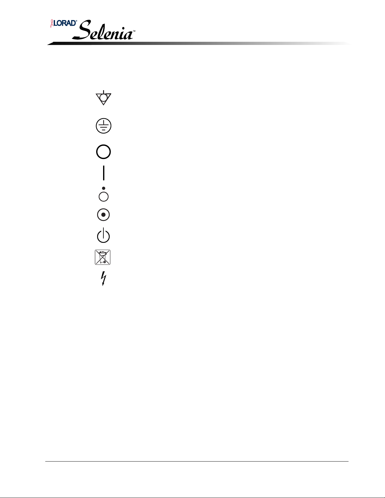
9.0 International Symbols
This section explains the International Symbols used on this system.
Installation and Hardware Maintenance Manual
Preface
International Symbols
Potential Equalization
terminal
Protective Earth terminal Used for the connection of the ground of the line cord or
Off Power disconnection from the mains
On Power connection to the mains
Off Off, only for a part of equipment
On On, only for a part of equipment
Power Standby Power On, Standby
WEEE (Waste Electrical
and Electronic Equipment)
Connection for a conductor other than the Protective
Earth for a direct connection between two or more pieces
of electrical equipment.
ground cable of the equipment and no other purpose.
Symbol indicating separate collection for electrical and
electronic equipment
Dangerous Voltage Identifies area of potentially lethal voltage
MAN-00745 ix
Page 28

Installation and Hardware Maintenance Manual
Preface
Using the Installation and Hardware Maintenance Manual
10.0 Using the Installation and Hardware Maintenance Manual
This manual is written for the Selenia system hardware, and describes the mechanical
controls, accessories, and the instructions for starting the system. Refer to the Selenia
Calibration and Software Maintenance Manual for information and instructions relating to
the Selenia software application.
A typical Selenia installation begins with hardware installation and functional testing
(Chapter 2 through Chapter 5), and continues using the Calibration and Software
Maintenance Manual.
Chapter 1—General Information. This chapter provides an overview of the
mammography system, including component descriptions, patient and user safety,
interlocks, room planning, and compliance information.
Chapter 2—Gantry Installation. This chapter provides details of setup, positioning,
and installation of the Gantry and Image Receptor in the exam room.
Chapter 3—AWS Installation with TechMate. This chapter contains information to
install the Workstation with the TechMate option.
Chapter 4—AWS Installation without TechMate. This chapter contains
information to install the AWS without the TechMate option.
Chapter 5—Startup, Shutdown, and Functional Tests. This chapter contains
information on the pre and post-startup tests, the Startup, Shutdown, and Emergency
Operating procedures.
Chapter 6—AWS Maintenance. This chapter contains preventive maintenance and
replacement information for the TechMate and AWS.
Chapter 7—Gantry Maintenance. This chapter provides maintenance information
and instructions for the Gantry.
Appendix A—Specifications. This appendix contains abbreviated specifications, and
center-of-gravity information.
Appendix B—Using Selenia in a Mobile Environment. This appendix describes
the use of the Selenia in a mobile environment.
Appendix C—Technical References. This appendix provides additional technical
references to be used as aids in troubleshooting Selenia.
Appendix D—Parts List. This appendix provides tabular listings of the serviceable
components in Selenia. Part numbers and descriptions are provided for component
identification.
Appendix E—Alternate AWS Arm Configuration. This appendix provides
information and instructions to reconfigure the Selenia Display Arm.
Appendix F—Installation Checklist. This appendix provides a checklist of procedures
to follow during the installation of the Selenia.
x MAN-00745
Page 29
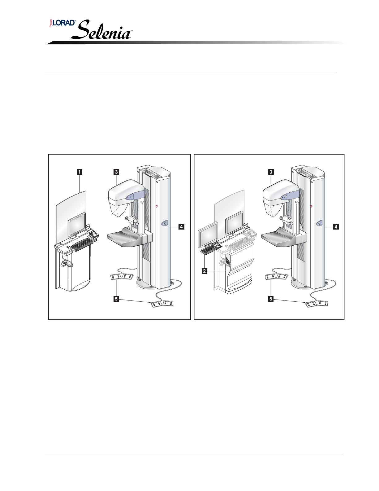
Installation and Hardware Maintenance Manual
Chapter 1—General Information
1.0 Introduction
This chapter provides an overview of Selenia, including component descriptions, patient and
user safety, interlocks, and compliance information.
2.0 System Description
The Selenia is available with a technologist review workstation (the Hologic SecurViewRT
TechMate). In the TechMate configuration, the SecurView
reduce space in the examination room.
Chapter 1—General Information
Introduction
is packaged with the Selenia to
RT
Figure 1-1: Selenia System Description
Legend for Figure 1-1
1. The Selenia Acquisition Workstation contains the image processing electronics and provides the
operator interface.
2. The SecurView
3. The C-arm provides a platform for the x-ray tube, compression systems, and the digital image
receptor. A pivot mechanism connects the C-arm to the Gantry.
4. The Gantry contains the electrical and mechanical subsystems for the Selenia. The C-arm and the
Gantry make up the Tubesta nd.
5. Dual-function Footswitches allow hands-free C-arm vertical travel and compression movements.
MAN-00745 1-1
TechMate technologist review workstation.
RT
Page 30
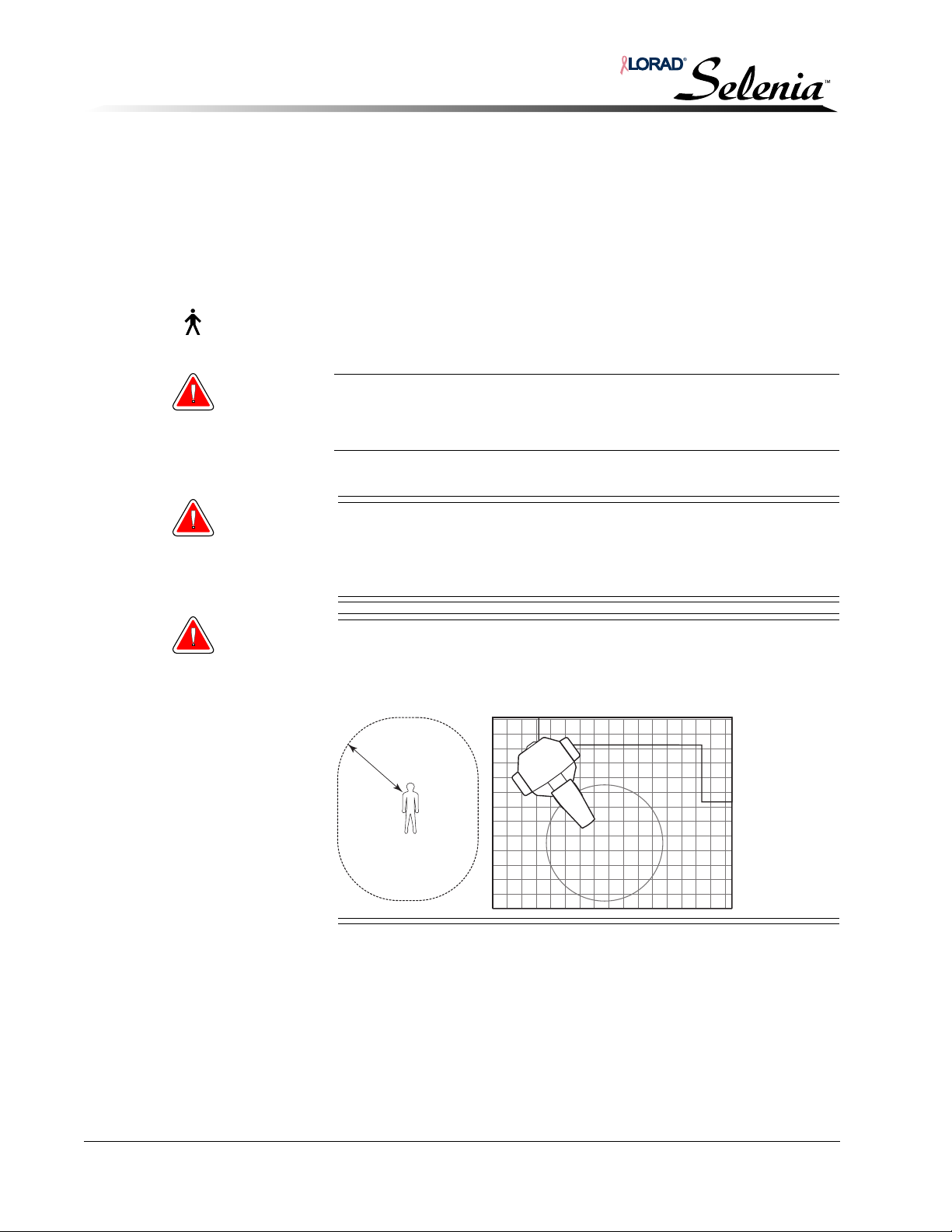
Installation and Hardware Maintenance Manual
1.5m
Chapter 1—General Information
Film Printer (option)
3.0 Film Printer (option)
Printers are available for printed film. Printed films have the patient information, exposure
technique, projection, and institution information displayed.
4.0 Safety
This manual should be read and understood in its entirety before turning the unit On. Always
follow all the instructions in this manual.
The Selenia system is classified as CLASS I, TYPE B permanently connected
equipment as per IEC 60601-1. There are no special provisions to protect
the system from flammable anesthetics or ingress of liquids.
Warning: This x-ray unit may be dangerous unless safe exposure factors and
operating instructions are followed. Observe all operating and
safety instructions before making an x-ray exposure.
4.1 Isolation Integrity
WARNING! To ensure the isolation integrity for the system, attach only
Hologic accessories or options to the unit. Any changes to the
interconnections must be performed by Hologic authorized
personnel.
WARNING! To insure proper isolation, maintain a 1.5 meter distance
between the patient and any non-patient devices. Non-patient
system components (such as the Workflow Manager, or the
hardcopy printer) must not be installed in the Patient Area.
1-2 MAN-00745
Page 31
4.2 Radiation Safety
The exposure duration is limited by the following normal conditions:
• The manual mAs timer
The exposure duration is also limited by the following abnormal conditions:
• Premature release of the x-ray exposure switch
• Exceeding the preset back-up time
• The independent safety hardware back-up timer
• Detection of a generator fault
4.2.1 Operator Radiation Shield
The unit’s radiation shield is designed to comply with all requirements of 21CFR
1020 and IEC 60601-2-45.2001. The shield is rated for a 0.5 mm Pb (lead)
equivalence and is permanently mounted to the AWS.
Warning: For maximum protection from x-ray exposure, the operator must
keep their entire body behind the radiation shield for the duration
of the exposure.
Installation and Hardware Maintenance Manual
Chapter 1—General Information
Safety
4.2.2 Exam Room Door Indicators
• Power On Indicator—There is a provision in the system to accommodate local
regulations that require an x-ray System Power-On Indicator at the door.
• X-ray On Indicator—There is a provision in the system to accommodate local
regulations that require an x-ray Exposure In Progress indicator at the door.
4.3 Electrical Safety
Only an authorized service engineer should remove covers from the mammography unit.
WARNING! Lethal voltages are present within the interior of this unit.
WARNING! Electrical equipment used in the presence of flammable
anesthetics or oxygen may cause an explosion.
WARNING! The Disk Drives equipped with this system are a Class I Laser
Product. Avoid direct exposure to the beam. Invisible laser
radiation is present if the case to a disk drive is open.
WARNING! The Bar Code Scanner equipped with this system is a Class II
Laser Product. Avoid direct exposure to the beam. Invisible
laser radiation is present if the cover is opened.
MAN-00745 1-3
Page 32
Installation and Hardware Maintenance Manual
Chapter 1—General Information
Safety
WARNING! Per North American electrical safety requirements, grounding
reliability can only be achieved when the Acquisition
Workstation is connected to a receptacle marked Hospital
Grade.
Caution: Do not store any magnetic media near or on devices, which produce
magnetic fields, since stored data may be lost.
Caution:
Caution:
Caution:
Caution:
Never switch off the Uninterruptible Power Supply (UPS) except in
emergency (due to the risk of data loss).
To minimize potential damage from thermal shock to the Digital Image
Receptor, follow the recommended procedure to turn off the equipment.
Only Selenia recommended accessories should be used with this
equipment. Failure to heed this warning may cause unexpected functions
and possible data loss.
This is a medical device and should not be considered to be a general-purpose
computer. Users or service/administrative personnel may not amend,
configure, or modify any hardware or software on this medical device with
anything other than Hologic-approved components or software, including
anti-virus software. This device should be installed behind the institution
firewall for network security and anti-virus protection. No ongoing computer
virus protection or network security for this medical device is provided (for
example, a computer firewall). Network security and anti-virus provisions are
the ongoing responsibility of the user.
1-4 MAN-00745
Page 33
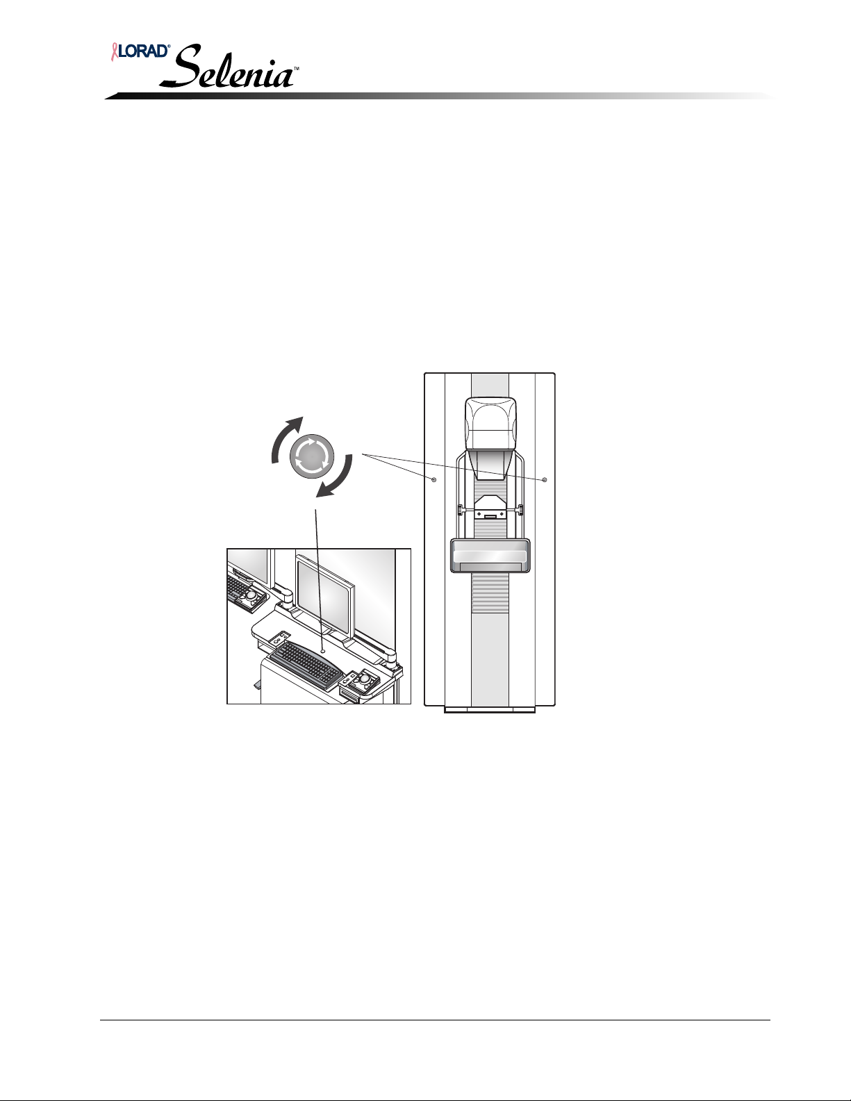
Installation and Hardware Maintenance Manual
4.4 Mechanical Safety
The equipment is designed to comply with the requirements of IEC 60601-1, UL 60601-1,
and CSA 22.2 No. 601.1 by these safety features:
• The C-arm rotation braking is ensured upon loss of power.
• Compression release is disabled when a localization paddle is installed.
• Motorized compression force is limited to 200 N (45 lb).
4.5 Emergency Off Switches
There are three Emergency Off Switches on the Selenia, one on either side of the Gantry and one
on the AWS. Do not use the Emergency Off Switches for routinely removing power from the
Selenia. The Emergency Off switch only affects the Gantry and should be used only in an
emergency. For details on its use, refer to Chapter 5, Section 8.0, p. 5-18.
Chapter 1—General Information
Safety
Figure 1-2: Location of Emergency Off Switches
MAN-00745 1-5
Page 34

Installation and Hardware Maintenance Manual
Chapter 1—General Information
Safety
4.6 Interlocks
In addition to the Emergency Off Switches, Selenia has several other safety interlocks.
4.6.1 C-arm Movement Interlocks
C-arm vertical drive and rotation is disabled when 58 N (13 lb) or greater of
compression force is displayed.
4.6.2 Automatic Compression Release Interlock
Installing a Localization Paddle disables the automatic compression release functions.
4.6.3 Early Release Interlock
The two x-ray exposure switches must be activated and held throughout the entire
duration of the exposure. When the x-ray exposure switches are released prior to the
end of the exposure, this interlock causes immediate termination of the exposure.
An alarm message displays on the user interface.
4.6.4 Mirror and Filter Interlocks
These interlocks prevent x-ray exposure whenever the Light Field Mirror or the Filter
is not positioned correctly.
4.6.5 Smart Paddle System Position Interlock
When a breast examination (for example, 18 x 24 cm MLO view) is selected
requiring the use of an 18 x 24 cm (7.1 x 9.4 in.) shifting paddle, if the detected
position does not match the view, the acquisition computer prevents the x-ray
exposure until the faulty condition is corrected. A message is displayed to alert the
user.
1-6 MAN-00745
Page 35

5.0 Compliance
This section details the mammography system compliance requirements and the
manufacturer’s responsibilities.
5.1 Compliance Requirements
The manufacturer is responsible for the effects of safety, reliability and performance of this
equipment with the following provisions:
• The electrical installation of the room complies with the appropriate requirements.
• The equipment is used in accordance with instructions for use.
• Assembly operations, extensions, re-adjustments, modifications, or repairs are
performed by authorized persons only.
• The installed network and communications equipment must comply with an IEC Standard
and the complete system (network/communications equipment and Selenia
Mammography System) must be installed to comply with IEC 60601-1 and IEC 60601-1-1.
Installation and Hardware Maintenance Manual
Chapter 1—General Information
Compliance
5.2 Compliance Statements
The manufacturer states that this device is manufactured/conforms to:
• CAN/CSA: ISO 13485:2003
• FDA, 21 CFR [Parts 820, 900 and 1020]
• IEC 60601-1:1988 +A1+A2:1995 +A13:1996 Medical Electrical Equipment—General
requirements for safety
• IEC 60601-1-1:2000-12 Medical Electrical Equipment—Collateral Standard: Safety
requirements for medical electrical systems
• IEC 60601-1-2:2001 Medical Electrical Equipment—Collateral Standard:
Electromagnetic compatibility for medical electric systems
• IEC 60601-1-3:1994 Medical Electrical Equipment—Collateral Standard: Requirements
for radiation protection in diagnostic x-ray equipment
• IEC 60601-1-4:1996 +A1:1999 Medical Electrical Equipment—Collateral Standard:
Programmable electrical medical systems
• IEC 60601-2-28: 1993-03 Medical Electrical Equipment—Particular requirements for the
safety of x-ray source assemblies and x-ray tube assemblies for medical diagnosis
• IEC 60601-2-32:1994 Medical Electrical Equipment—Particular requirements for the
safety of associated equipment of x-ray equipment
• IEC 60601-2-45:2001 Medical Electrical Equipment—Particular requirements for the
safety of mammographic x-ray equipment and mammographic stereotactic devices
• UL 60601-1: Medical Electrical Equipment, Part 1—General Requirements for Safety
• CSA: Medical Electrical Equipment Part 1: C22.2601 No. 601.1–M90—General
Requirements for Safety
MAN-00745 1-7
Page 36
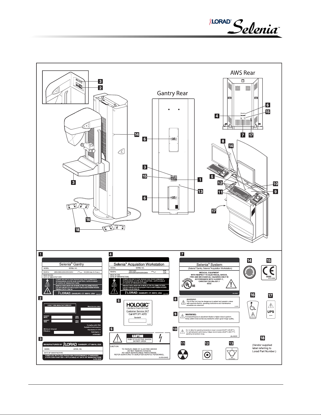
Installation and Hardware Maintenance Manual
Chapter 1—General Information
Compliance
5.3 Label Locations
1-8 MAN-00745
Page 37
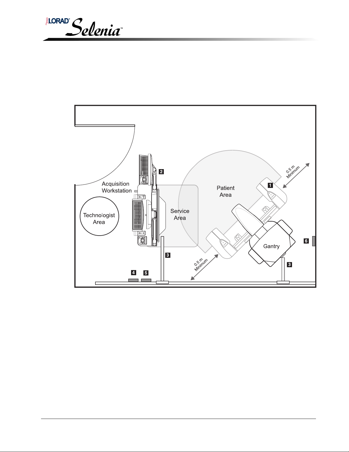
6.0 Room Planning
The exam room layout should be pre-planned before the arrival of Selenia. A Typical Room
Layout is shown in Figure 1-3. Measure the height and width of the room door to ensure it
accommodates the Gantry and AWS, 190 cm high, 76 cm wide minimum (75 in. x 30 in.);
refer to “Appendix A—Specifications” on p. A-1.
Installation and Hardware Maintenance Manual
Chapter 1—General Information
Room Planning
Figure 1-3: Selenia—Typical Room Layout
1. Tubestand
2. Acquisition Workstation
3. Wireways
4. Network Outlet
5. 120 Vac Outlet 2 Ganged
6. 208 Vac Disconnect Box
MAN-00745 1-9
(with TechMate)
Legend for Figure 1-3
Page 38
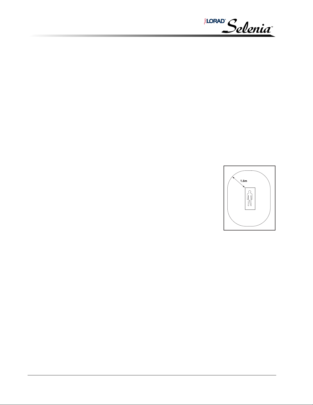
Installation and Hardware Maintenance Manual
Chapter 1—General Information
Room Planning
Other factors to consider when planning the room layout are:
1. C-arm clearances—The C-arm requires 135 cm (53 in.) minimum to accommodate
rotation, and 213 cm (84 in.) to accommodate raising the C-arm to its upper limit.
2. When planning the room layout, take into consideration extra wall and ceiling clearance
for movement and handling of C-arm controls.
3. Movement clearance—Always take into consideration space allocation for patient and
technologist movement. Avoid obstructions in the room that may hinder access to the
unit controls or the patient.
4. Storage—Provide convenient storage for patient records and system accessories. If
accessory storage is not possible within the exam room, make arrangements for safe
storage close by.
5. Physical and Environmental Requirements—
• Operating Temperature Range—20 °C to 30 °C (68 °F to 86 °F)
• Operating Humidity Range—10% to 80% non-condensing
• Refer to Appendix A of the Selenia Installation and Hardware Maintenance Manual
for complete system specifications.
6. To ensure proper isolation, a distance of 1.5 m (59 in.) must be
maintained between the patient and any non-patient devices.
1-10 MAN-00745
Page 39
7.0 Receiving and Unpacking
Required Tools:
• Electric screw gun with #2 Phillips screw head driver
• Small crowbar or claw hammer
7.1 Receiving Instructions
Selenia is shipped in containers that hold the:
•Gantry
• Acquisition Workstation (with or without TechMate)
• Radiation Shield
• Image Receptor (IR)—The IR usually does not arrive until the second day.
• Accessories and additional or optional equipment
Note… If there is a discrepancy between the contents and the packing list or sales
order, contact Hologic immediately. If it is necessary to repack any items for
future installation, use the original packaging materials.
Installation and Hardware Maintenance Manual
Chapter 1—General Information
Receiving and Unpacking
Note… If shipping damage is of a concealed nature, contact the carrier as soon as
such damage is found, and request an inspection for shipping damage.
Normally, any claims for shipping damage must be completed within 15
days of receiving the shipment.
Upon receipt, perform the following before opening the containers:
1. Inspect each container for damage.
2. Note any damage on the shipping manifest.
3. Notify Hologic of any external shipping damage that may have occurred.
7.2 Uncrating the Gantry
The Selenia Gantry is crated and shipped in a prone position—Figure 1-4, p. 1-12.
WARNING! Be sure to have the necessary machinery and personnel available to
move heavy medical equipment safely.
WARNING!
To prevent injury to personnel and/or damage to equipment, care
must be taken when uncrating the equipment.
MAN-00745 1-11
Page 40
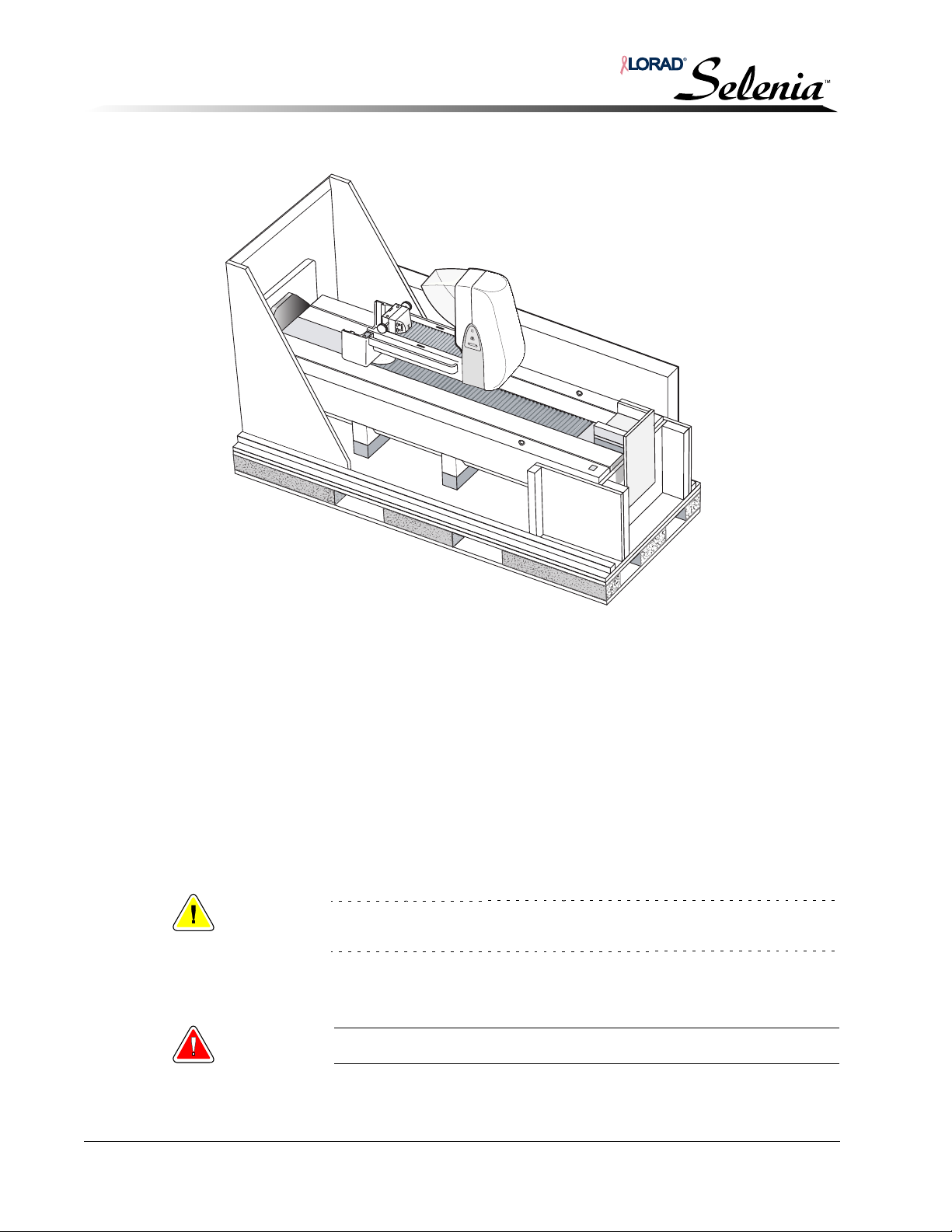
Installation and Hardware Maintenance Manual
Chapter 1—General Information
Receiving and Unpacking
Figure 1-4: Uncrating the Gantry
Uncrate the Gantry as follows:
1. Cut the retaining straps that secure the container top to the shock-mounted wooden
pallet.
2. Remove the nail holding the top to the pallet along the bottom of the cardboard.
3. Remove the screws that hold the shipping bracket for the tube.
4. Lift the container top off the unit.
5. Carefully remove all shipping materials (foam padding, tie-downs, straps, shipping wrap,
etc.) from the unit and pallet. Remove any accessory boxes from the pallet.
6. Open all boxes removed from Gantry crate and verify their contents against the packing
list and sales order.
7. Inspect each item for damage, then safely store them near the exam site.
Caution:
8. While still in the loading area, carefully move the pallet into an upright position.
To prevent damage, do not store the radiation shield flat. Avoid damage by
impact or scratching.
WARNING! The unit is top-heavy when in the upright position.
1-12 MAN-00745
Page 41
Installation and Hardware Maintenance Manual
Chapter 1—General Information
Receiving and Unpacking
Caution:
9. Remove the top collar securing the unit to the pallet. Using the installed dolly, carefully
roll the Gantry off the pallet.
Note… The dolly is not installed on units shipped overseas. For overseas sites,
10. Transport the Gantry from the loading area to the exam area for installation. Sites using
the hand-cart can skip Steps 9 and 11.
11. Remove the four bolts securing the Gantry to the dolly.
12. Carefully maneuver the Gantry off the back end of the dolly or hand-cart, slide the dolly
or hand-cart out and position the Gantry in the area of installation.
13. Return the dolly to Hologic, within 35 days from date of shipment, as per the return
shipment Bill of Lading (attached to either the dolly or the Gantry). If this documentation
is unavailable, please contact Field Service to acquire a Return Authorization number.
Be prepared to identify the site/customer and the Selenia serial number. Sites whose
scheduled installation date exceeds the 35 day requirement may request an extension
for returning the dolly.
Do not attempt to lift or move the Gantry by the C-arm or by either hinged
door on the left and right side of the Gantry frame, or damage may occur.
transport the Gantry from the loading area to the exam area on a hand-cart
whose rating exceeds the 300 kg (661 lb) weight.
7.3 Uncrating the Acquisition Workstation
The Selenia AWS is crated and shipped upright with the displays, display arms, and
TechMate trackball and keyboard not installed, and the radiation shield not attached.
Warning: Be sure to have the necessary machinery and personnel available to
move heavy medical equipment safely.
1. While still in the loading area, cut the straps securing the cardboard shipping carton to
the shock-mounted wooden pallet. Lift the carton from the pallet.
2. Carefully remove all shipping materials (foam padding, tie-downs, straps, shipping wrap,
etc.) from the unit and pallet. Remove any accessory boxes from the pallet, including the
AWS display.
3. Open all boxes removed from the crate and verify their contents against the packing list
and sales order.
4. Inspect each item for damage, then safely store them near the exam site.
5. Remove the screws in the three wooden boards that hold the AWS to the pallet.
6. Carefully remove the AWS from the pallet and transport it from the loading area to the
exam area.
Caution:
The Shield is tempered glass. Don’t drop the shield or lay down flat.
MAN-00745 1-13
Page 42
Installation and Hardware Maintenance Manual
Chapter 1—General Information
Receiving and Unpacking
7.4 Unpacking the Image Receptor
Caution: Move Image Receptor to a controlled area prior to unpacking.
Caution:
Note… The Image Receptor shipping container is specially designed to minimize
Note… If shipping damage is of a concealed nature, contact the carrier as soon as
1. Upon receipt of the Image Receptor, move the Image Receptor to a controlled area
which meets the environmental requirements listed below:
• Storage Temperature Range—10 °C to 40 °C (50 °F to 104 °F)
• Storage Humidity Range—10% to 80% non-condensing
2. Open the shipping container and inspect unit for damage.
3. Press the button on the temperature monitor. The LED should be green. If not, contact
Service.
Extreme care should be taken during unpacking to prevent damage.
shipping damage and to facilitate storage. A temperature monitoring device
is included in the shipping container.
such damage is found, and request an inspection for shipping damage.
Normally, any claims for shipping damage must be completed within 15
days of receiving the shipment.
1-14 MAN-00745
Page 43
Installation and Hardware Maintenance Manual
Chapter 2—Gantry Installation
1.0 Overview of Entire Installation Process
The following sections detail setting up, positioning, and installing Selenia in the exam room.
Note… The installed network and communications equipment must comply with
an IEC Standard and the complete system (network/communications
equipment and Selenia Mammography System) must be installed to comply
with IEC 60601-1 AND IEC 60601-1-1.
Note… Thoroughly read all procedures prior to starting.
1. Position the Gantry and the AWS in the area of the exam room where the unit is
permanently installed.
2. Verify, with the technicians and doctors, the proper placement.
3. Be sure the Gantry is positioned for easy access to the rear panels.
4. Perform the following installation procedures in the order described in this chapter.
Chapter 2—Gantry Installation
Overview of Entire Installation Process
2.0 Securing the Gantry in Position
1. Position the Gantry in the exam room in a location satisfactory to the technicians and the
doctors. Ensure the circuit breaker and rear panels are accessible.
Caution:
2. On the floor, mark the four holes of the Gantry with a marker and move the Gantry back
to allow you to access the marks for hole drilling.
3. Drill the anchor holes and set the inserts.
4. Position the Gantry over the holes and bolt in accordance with site specification
drawings and/or local building codes.
Never maneuver the Gantry by lifting, pulling, or pushing on the C-arm or
the tubehead assemblies. With proper equipment, the Gantry may be
moved by the two Eye Hooks on the top.
MAN-00745 2-1
Page 44
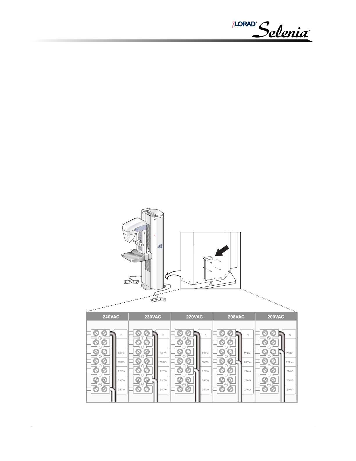
Installation and Hardware Maintenance Manual
Chapter 2—Gantry Installation
Gantry Input Power Configuration
3.0 Gantry Input Power Configuration
The isolation transformer in the Gantry must be configured to match the power source at the
site.
1. Before connecting the Gantry to a mains disconnect, verify the source voltage as
follows:
a. Measure the voltage at the outlet receptacle.
b. Inquire as to any history of voltage fluctuations or voltage-related problems that
have occurred in other equipment at the site.
2. After determining the input voltage range, verify the unit’s isolation transformer is
correctly set (reconfigure as required).
3. To access the power assembly chassis and re-configure the isolation transformer taps to
match the measured source voltage:
a. Set the circuit breaker on the rear of the Gantry to Off.
b. To access the input power terminal block, remove the Gantry’s lower rear panel (see
Figure 2-1) by removing the six screws.
c. Verify the isolation transformer taps are wired to match the previously measured
source voltage; if it does not, configure the isolation transformer input wiring and
tap as shown.
Figure 2-1: Isolation Transformer Taps—Gantry
2-2 MAN-00745
Page 45
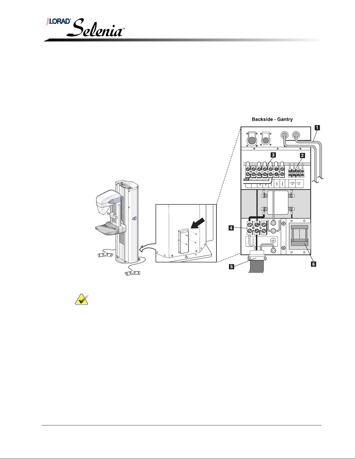
Installation and Hardware Maintenance Manual
Legend for Figure 2-2
1. Footswitch Connectors
2. Power On/x-ray On Terminal Block
3. Isolation Transformer Taps
4. Input Power Terminal Block
5. Input Power Cord (Gantry)
6. Circuit Breaker
3.1 Power Cable Connection
1. Ensure that the circuit breaker is off.
2. Connect the input power cord—Figure 2-2, to the input power terminal block on the
rear of the Gantry.
3. Hard wire the opposite end of the input power cord into the power source via a
disconnect panel. This must be done by a certified electrician.
Chapter 2—Gantry Installation
Gantry Input Power Configuration
MAN-00745 2-3
Figure 2-2: Power, X-ray On, and Footswitch Connections
Note… You will make the connections to the AWS in Chapter 3, Gantry to
Acquisition Workstation Interconnections, p. 3-3.
Page 46
Installation and Hardware Maintenance Manual
Chapter 2—Gantry Installation
Footswitch Installation
4.0 Footswitch Installation
The system permits attachment of two dual-function footswitches that plug into receptacles
on the Gantry connector panel—Figure 2-2, p. 2-3, item #1.
Connect the footswitches:
1. Connect the footswitch to one of the footswitch receptacles by aligning the key to the
key hole and pushing the connector straight in.
Note… Either footswitch can be connected to either footswitch receptacle.
2. Position the footswitch in the desired location on the floor below the C-arm.
3. Repeat Steps 1 and 2 for the second footswitch.
Warning: To avoid accidental footswitch activation, keep both footswitches
clear of the patient and C-arm setup area.
2-4 MAN-00745
Page 47
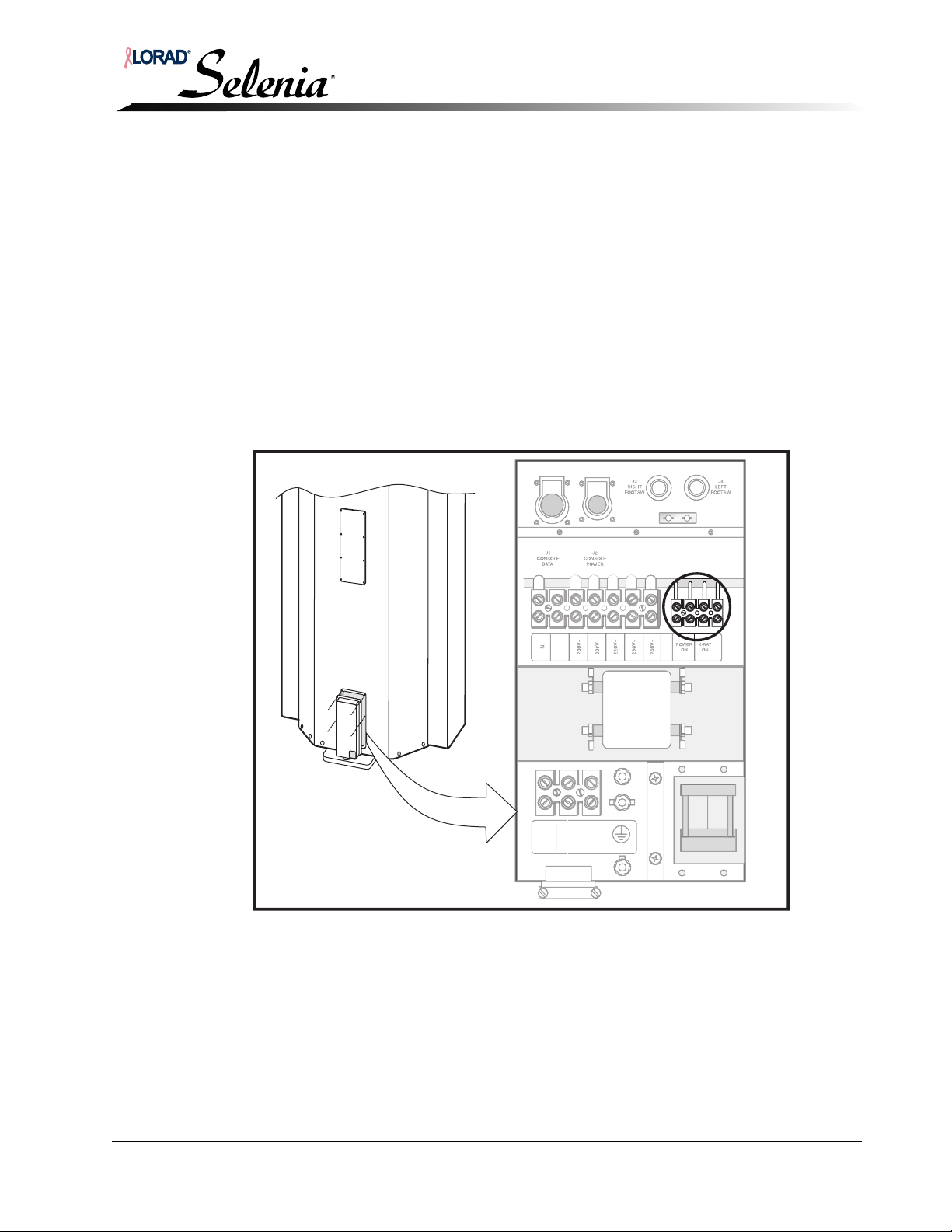
Installation and Hardware Maintenance Manual
Chapter 2—Gantry Installation
Remote X-ray On/Power On Light—Connection
5.0 Remote X-ray On/Power On Light—Connection
Selenia provides the user with the ability to operate remote lights which indicate when the
system is On and when x-rays are being taken. These lights are normally installed above the
door to the exam room. Installation should be done by a certified electrician. The relay
contacts provided are rated:
• 10 A 250 VAC (normally open)
• 10 A 30 VDC (normally open)
The connection points are available through the access panel at the rear of the Gantry, as
shown in Figure 2-3. Connections are made on the Power On/x-ray On terminal block:
1. Install the remote Power On/x-ray On lights following local guidelines.
2. Route the remote cables from the lights to the Gantry and connect each cable to the
appropriate location on the Power On/x-ray On terminal block.
Figure 2-3: Access to Power On and X-ray On Indicators
MAN-00745 2-5
Page 48
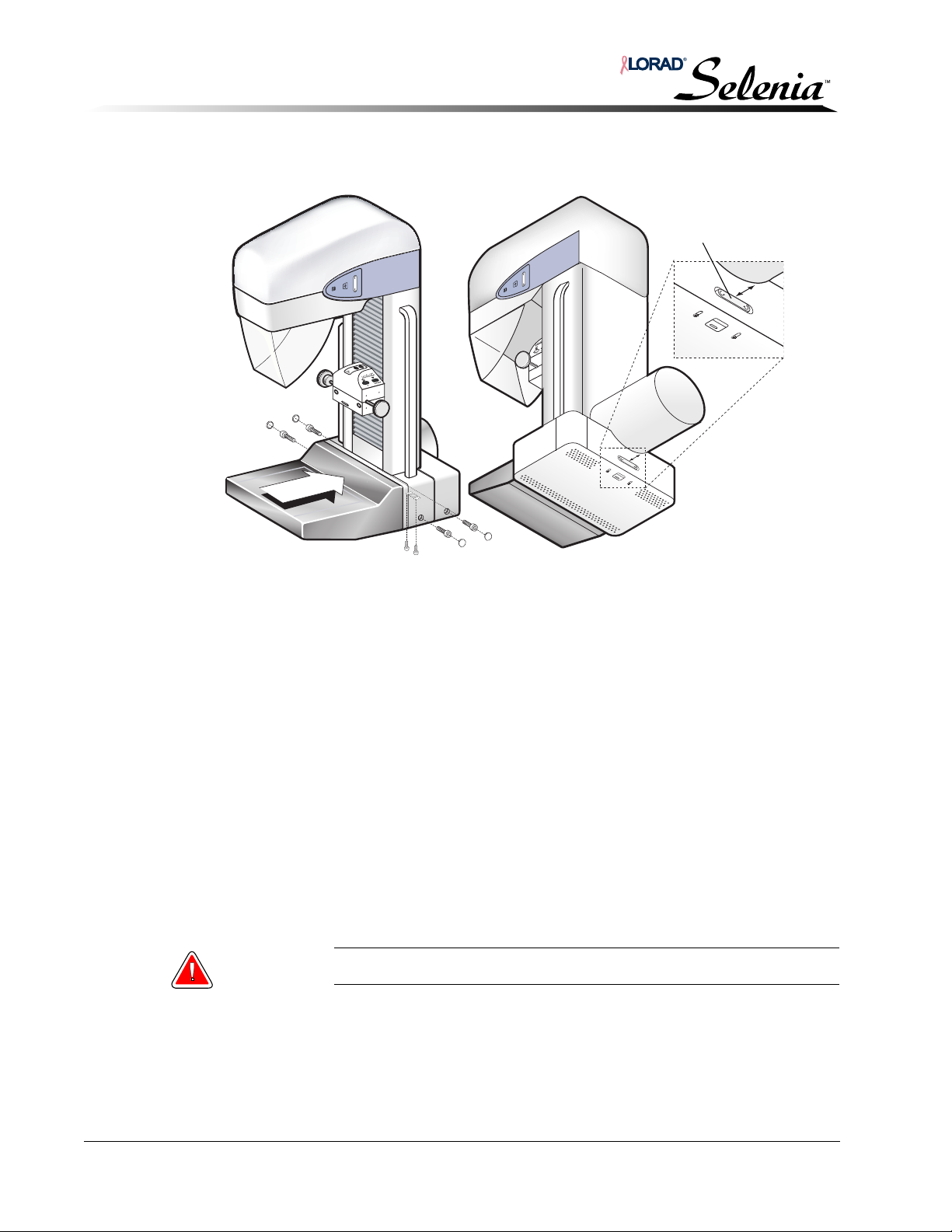
Installation and Hardware Maintenance Manual
Switch Assembly
Chapter 2—Gantry Installation
Installing the Image Receptor
6.0 Installing the Image Receptor
Figure 2-4: Image Receptor
6.1 Image Receptor Installation
1. Remove the Image Receptor from the shipping container.
2. On the bottom of the Image Receptor, loosen the two screws securing the C-arm switch
assembly in position.
3. Slide the rear of the Image Receptor into the guide rails on the bottom of the C-arm
assembly. Ensure the Image Receptor is firmly seated.
4. Secure in place using two bolts on each side. Be sure to use all four bolts.
5. Install the provided decorative caps over each bolt.
6.2 Adjusting the C-arm Rotation Switch Assembly
An additional C-arm Rotation switch assembly is located at the rear of the Image Receptor
and must be adjusted so it is seated within the C-arm switch assembly access hole on the
back of the C-arm frame. See Figure 2-4, p. 2-6.
1. Access the elongated holes for the switch assembly at the bottom of the Image Receptor.
2. Loosen the screws and slide the switch assembly forward until it is fully positioned
within the access hole on the rear of the C-arm frame.
Warning: Make sure the switches are not permanently actuated.
3. Tighten the screws.
6.3 Shipping Container Return
Return the shipping container and the temperature monitoring device to Hologic as per the
instructions in the container.
2-6 MAN-00745
Page 49
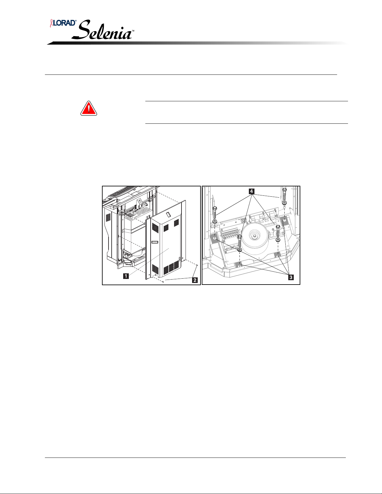
Installation and Hardware Maintenance Manual
Legend for
Figure 3-1
1. Rear Cover
2. Rear Cover
Screws
3. Mounting
Holes
4. Anchor Bolts
and Washers
Chapter 3—AWS Installation with TechMate
Securing the Acquisition Workstation (AWS) in Position
Chapter 3—AWS Installation with TechMate
1.0 Securing the Acquisition Workstation (AWS) in Position
Warning: Be sure to have the necessary machinery and personnel available to
move heavy medical equipment safely.
1.1 Removing the Rear Cover
Refer to Figure 3-1.
1. Remove the two bottom screws securing the rear cover to the rear of the AWS.
2. Slide the rear cover up to free the hooks from the slots in the rear of the AWS frame.
3. Disconnect the cooling fans’ power cable. Set the cover aside.
Figure 3-1: Acquisition Workstation—Installation and Cover Removal
1.2 Mount the AWS
1. Position the AWS in the exam room in a location satisfactory to the technicians and the
doctors.
2. Mark the four holes of the AWS with a marker and move the unit back to access the
marks. See Figure 3-1.
3. Drill the anchor holes and set the inserts.
4. Secure the AWS to the floor using the required anchor bolts and washers in accordance
with site specification drawings and/or local building codes.
MAN-00745 3-1
Page 50
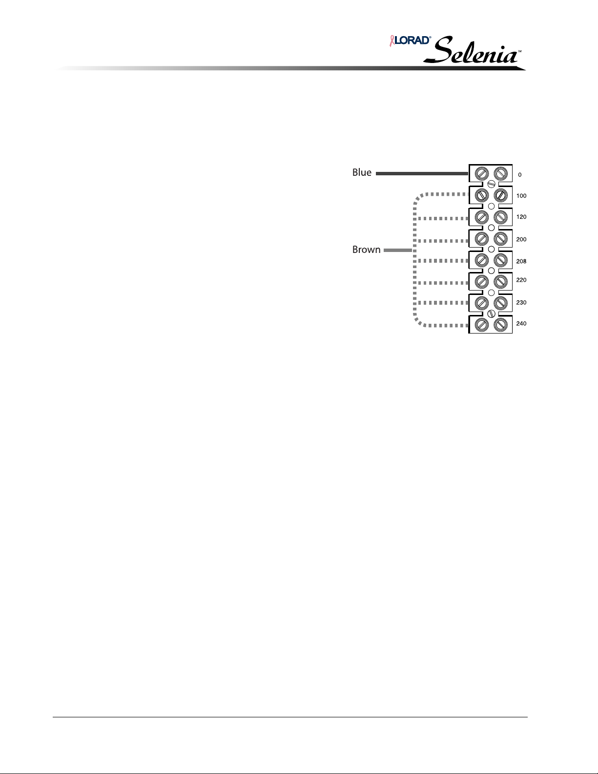
Installation and Hardware Maintenance Manual
Chapter 3—AWS Installation with TechMate
Input Power Configuration
2.0 Input Power Configuration
Refer to Section 2.1.
2.1 Acquisition Workstation
The isolation transformer within the AWS must
be configured to 100, 120, 220, 230, or 240
VAC. After determining the correct VAC for the
site, verify the AWS’s isolation transformer is
correctly set. Reconfigure the taps to match site
power requirements as required.
1. Verify the isolation transformer taps (Figure
3-2) are wired to the site voltage
requirements; if they are not, configure the
isolation transformer input wiring and taps as
shown in Figure 3-2.
Figure 3-2: Input Power Configuration—Acquisition Workstation
2. Verify circuit breaker CB1 current rating is as follows:
• for domestic, CB1 = 8.0 A
• for International, CB1 = 3.5 A
3-2 MAN-00745
Page 51
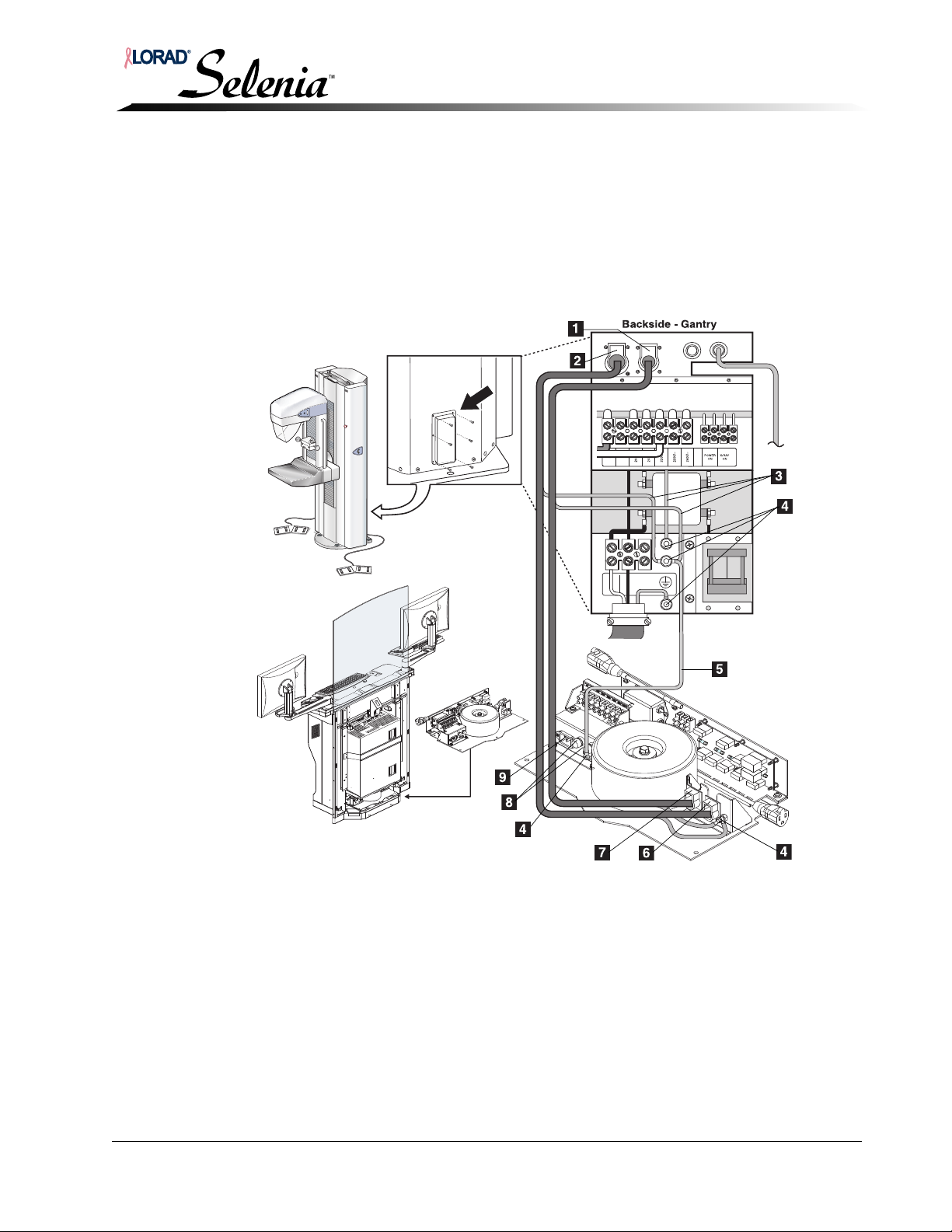
Installation and Hardware Maintenance Manual
Chapter 3—AWS Installation with TechMate
Gantry to Acquisition Workstation Interconnections
3.0 Gantry to Acquisition Workstation Interconnections
3.1 Power
1. At the rear of the AWS, connect one end of the power cable to the Power Out to Gantry
receptacle (#8, Figure 3-3) on the AWS Power Distribution Assembly.
2. Connect the power cable to the J
connector panel.
3. Make the remaining connections as shown in Figure 3-3.
2 Acquisition Power receptacle (#2,) on the Gantry
.
Figure 3-3: Gantry to Acquisition Workstation Interconnections
Legend for Figure 3-3
1. J2 Acquisition Power receptacle
2. J1 Acquisition Data receptacle
3. Data and Power Cable Ground Wires
4. Ground Studs
5. Equipotential Ground Wire
6. Data Receptacle
7. Power Out to Brick and Gantry Control
8. Brick Power Fuses (2A FB, 250VAC)
9. Input Power Receptacle (AWS)
4. Connect one end of the AWS input power cord to the AWS input power receptacle
(#9, Figure 3-3) on the AWS Power Distribution Assembly and plug the other end into
site power.
MAN-00745 3-3
Page 52
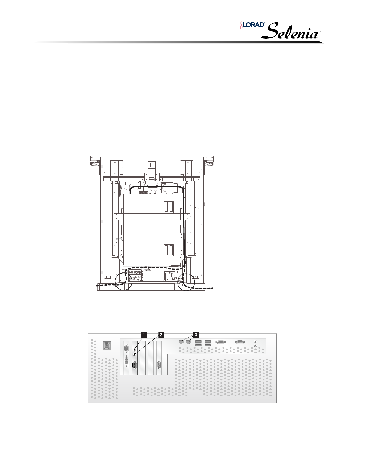
Installation and Hardware Maintenance Manual
Legend for
Figure 3-5
1. Rx—Blue
Wire
2. Tx—Orange
Wire
3.
Network
Cable
Chapter 3—AWS Installation with TechMate
Gantry to Acquisition Workstation Interconnections
3.2 Fiber Optics
The fiber optic cables are connected between the Gantry and the AWS computer.
At the AWS:
1. Locate the cable clamp at the rear of the AWS below the cover handle. An identical
clamp is located on the opposite side of the AWS. All the AWS cabling exits from the
cutouts in the rear cover.
2. Route the fiber optic cable into the AWS as shown in Figure 3-4. The dotted line in the
illustration shows alternate entry paths into the AWS. Use the existing cable clamps
along each path for cable support.
3. Continue to route the cable into the AWS computer.
Figure 3-4: Fiber Optic Cabling, Acquisition Workstation
4. Connect the fiber optic cable into the termination points at the rear of the computer—
Figure 3-5.
Figure 3-5: Fiber Optic and Network Cable Termination Points
5. Allowing for a service loop, secure the wiring with cable ties.
3-4 MAN-00745
Page 53
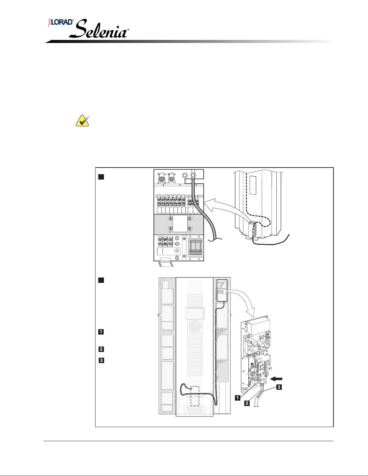
Installation and Hardware Maintenance Manual
Entry
Routing and
Termination
(Rear view of
the Gantry)
(Front view of
the Gantry)
Three LEDs:
1 red, 2 green
Orange Wire
Blue Wire
Chapter 3—AWS Installation with TechMate
Gantry to Acquisition Workstation Interconnections
At the Gantry
1. Route the cable into the Gantry through the rear lower access panel. A cutout on the
power panel allows entry into the Gantry mainframe. See inset ‘A’ below.
2. Following the Main Harness inside the Gantry mainframe, route the fiber optic cable up
to the Brick. See inset ‘B’ below. Connect the cable to the Brick.
Note… It is possible to install the fiber optic cable incorrectly (reversed). If they are
reversed, the red LED is on. When correct, the red LED is off, the right green
LED is on, and the center LED blinks.
3. Allowing for a ‘service loop’, secure the wiring with cable ties.
4. Secure the fiber optic cable to the bulk cabling from the Gantry to the AWS.
5. Reattach the lower rear panel and turn on the wall and Gantry circuit breakers.
J3
RIGHT
A
CONSOLE
FOOTSW
J2
J1
CONSOLE
POWER
DATA
J4
LEFT
FOOTSW
N
200V~
POWERONX-RAY
208V~
220V~
ON
230V~
240V~
B
Figure 3-6: Fiber Optic Cabling, Gantry
MAN-00745 3-5
Page 54
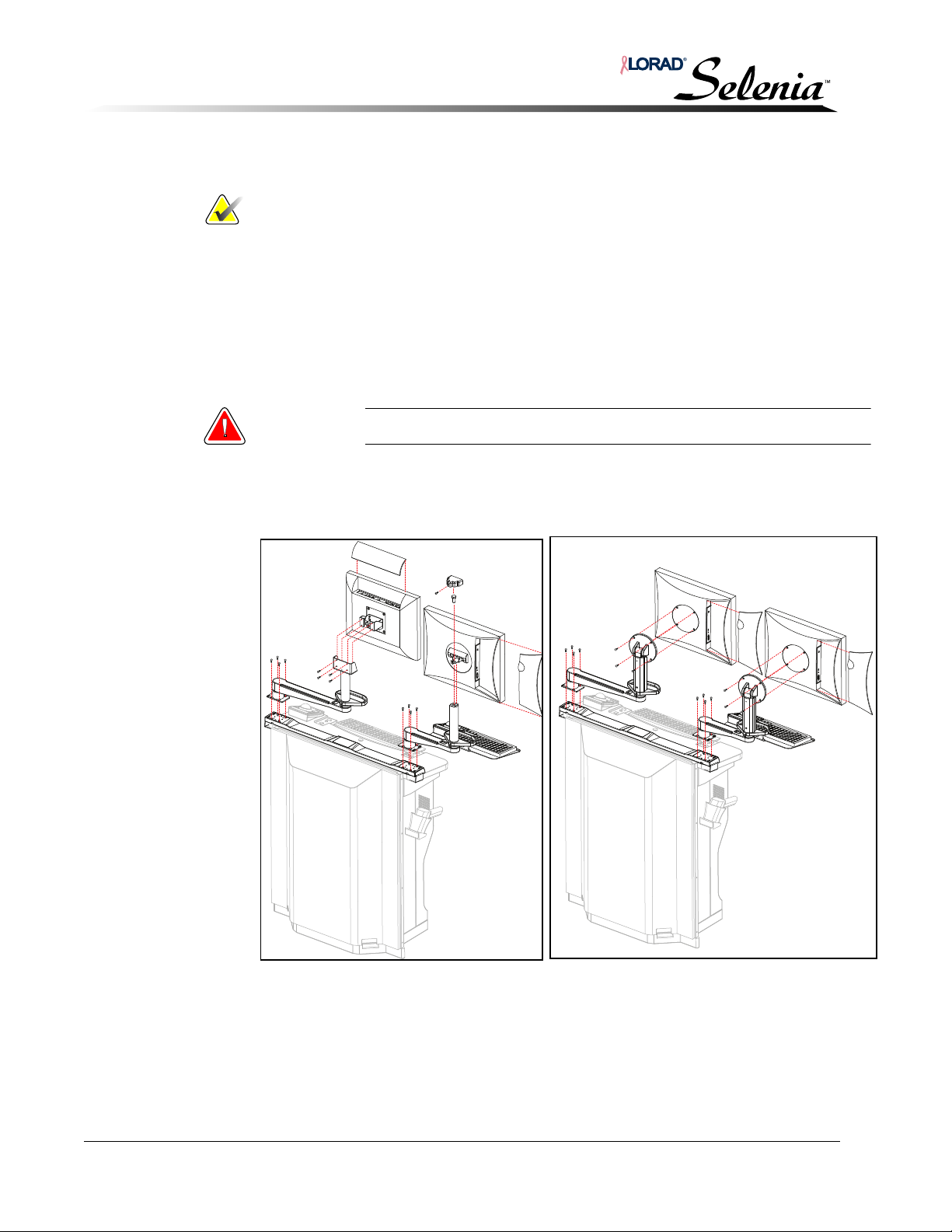
Installation and Hardware Maintenance Manual
Totoku
Display
Totoku
Display
Barco
Display
Chapter 3—AWS Installation with TechMate
Standard Configuration
4.0 Standard Configuration
Note… In the standard configuration, the Selenia display is installed on the right
side of the AWS, and the TechMate display, keyboard, and trackball are
installed on the left side of the AWS. Optionally, the Selenia display is
installed on the left side of the AWS, and the TechMate display, keyboard,
and trackball are installed on the right side of the AWS. For the optional
configuration, go to “Optional Configuration” on p. 3-11.
If you are installing the AWS without the TechMate, go to “Chapter 4—AWS
Installation without TechMate” on p. 4-1.
4.1 Displays, Swivel Arm, and Display Arm Attachment
Warning: Two people are required to safely perform this procedure.
1. Install the arms on the base, ensuring that, on each side of the unit, the elongated holes
are positioned toward the outside of the unit.
2. Install the displays on the arms.
Figure 3-7: Display, Swivel Arm, and Display Arm Attachment
3-6 MAN-00745
Page 55
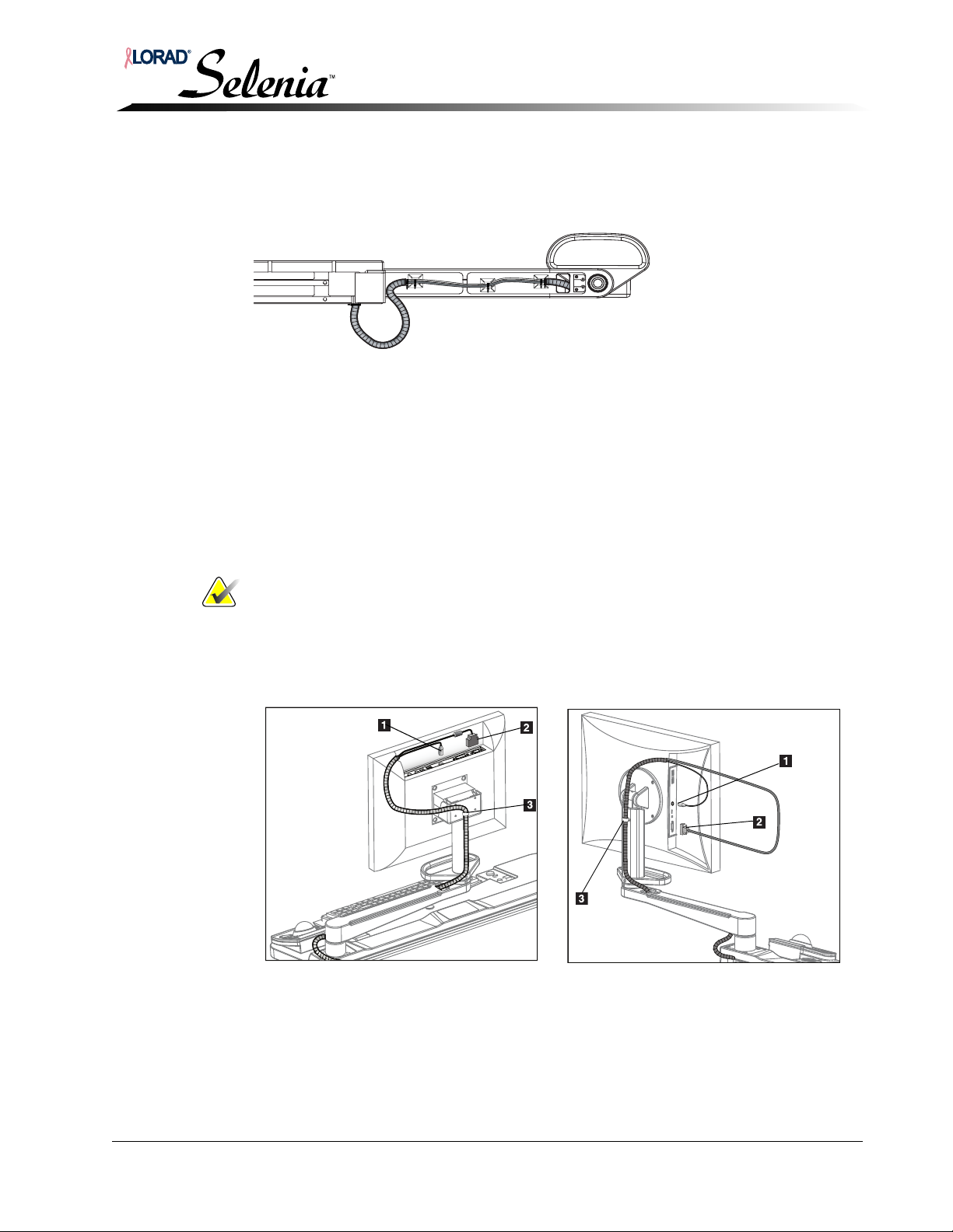
Installation and Hardware Maintenance Manual
Totoku
Display
Barco
Display
Chapter 3—AWS Installation with TechMate
4.1.1 Arm Harness Routing—Selenia
Referring to Figure 3-8, route the harness through the bottom of the arm, and secure
with cable ties.
Figure 3-8: Selenia Harness Routing Through the Display Arm
4.1.2 Display Cables Attachment—Selenia
Refer to Figure 3-9.
1. Remove the cover (not shown) from the Display’s compartment to provide
access to the connectors.
2. Connect the display power cable to the power connector of the display.
3. Connect the VGA(Tototku), or DVI (Barco) cable to the VGA/DVI port of the
display.
Standard Configuration
Note… Carefully position the VGA/DVI cable’s ferrite core so the cover closes
easily. Be sure the cover is fully latched.
4. Ensure full range of motion on the Selenia swing-arm.
5. Tighten the cable clamp.
6. Reinstall the cover on the Display’s compartment.
Legend for Figure 3-9
1. Power Supply Cable
2. VGA/DVI Cable
3. Cable Clamp
Figure 3-9: Selenia Display Connections
MAN-00745 3-7
Page 56
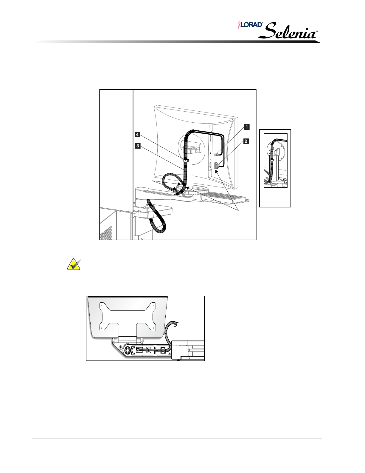
Installation and Hardware Maintenance Manual
12 in.
25 in.
minimum
New
Mount
Chapter 3—AWS Installation with TechMate
Standard Configuration
4.1.3 Display, and Arm Harness Routing—TechMate
1. Remove the display’s cover (not shown).
2. Connect the display power cable, and the DVI cable; see Figure 3-10.
Legend for Figure 3-10
1. Power Cable
2. DVI Cable
3. Spiral Wrap
4. Cable Clamp
Figure 3-10: TechMate Display Connections
Note… Allow for service loops as shown in Figure 3-10.
3. See Figure 3-11, and route the harness through the bottom of the arm, and
secure with cable ties.
4. Continue with Section 4.1.4, p. 3-9.
Figure 3-11: TechMate Harness Routing Through Swivel Arm
3-8 MAN-00745
Page 57
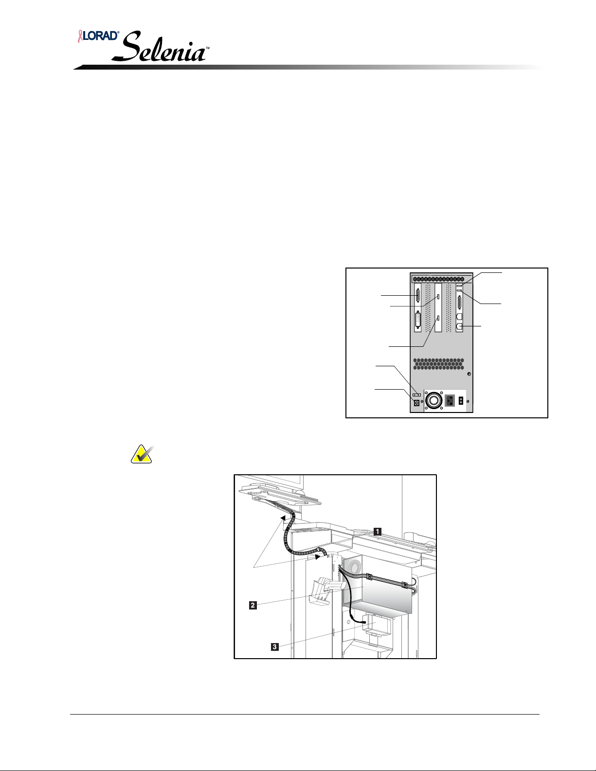
Installation and Hardware Maintenance Manual
To UP S
Dongle
Trackball
Keyboard
Display
‘Data Port’
Network Cable
Fan
Power
Switch
Legend for Figure 3-13
1. Cable Clamp
2. TechMate Computer
3. Display Power Module
20 in.
minimum
Chapter 3—AWS Installation with TechMate
Standard Configuration
4.1.4 Connect TechMate Keyboard, Trackball, and UPS Cables
Refer to Figure 3-12, and Figure 3-13.
Remove the AWS front cover:
1. Remove the two top screws securing the front cover to the front of the AWS.
2. Grasp the handles on the sides of the cover and slide upwards to free the hooks
from the slots in the front of the AWS frame.
3. Disconnect the cooling fans’ power cable, and the power switch cable from the
TechMate computer
4. Set the cover aside.
For cable routing see Figure 3-12 and Figure 3-13.
Connect the keyboard and trackball cables:
1. Position the TechMate
keyboard on the shelf and
connect the keyboard cable
to the TechMate computer.
2. Position the TechMate
trackball on the shelf and
connect the trackball cable to
the TechMate computer.
3. Dress the display, trackball
and keyboard cables, using
spiral wrap as shown.
Note… Allow for service loop as shown in Figure 3-13.
Figure 3-12: TechMate Connector Assignments
Figure 3-13: TechMate Harness Routing
MAN-00745 3-9
Page 58

Installation and Hardware Maintenance Manual
Chapter 3—AWS Installation with TechMate
Standard Configuration
Connect the UPS cables:
1. Disconnect the cables from the UPS. Note the position of the cables.
2. Remove the stop nut securing the Display Power Supply strap to the UPS
Mounting strap.
3. Remove the Display Power Supply.
4. Remove the nut from the bracket that secures the UPS to the workstation.
5. Remove the bracket.
6. Remove the UPS from the shelf.
7. While viewing the UPS from the front, lay the UPS on its left side, the front of
the UPS is to the left; The rear of the UPS is to the right.
8. Slide the battery compartment cover off of the UPS.
9. Grasp the tab attached to the battery and slide the battery partially out of the
case. Hold the battery firmly and pull it straight out.
The UPS is shipped with the internal red battery wire disconnected.
10. Connect the internal red battery wire to the positive (+) battery terminal.
11. Push the battery all the way into the battery compartment, and reinstall the
cover.
12. Reconnect the cables to the UPS.
13. Secure the UPS to the workstation with the previously removed bracket/nut.
14. Attach the Display Power Supply and bracket to the UPS bracket.
The UPS requires 8 hours to become fully charged. You can use the system while the
UPS is charging.
Check cabling and install covers:
1. Ensure full range of motion for the TechMate swing-arm.
2. Secure the cable harness.
3. Reinstall the cover on the display’s rear compartment.
4. Reinstall the AWS front cover reversing the steps described in Section 4.1.4.
3-10 MAN-00745
Page 59
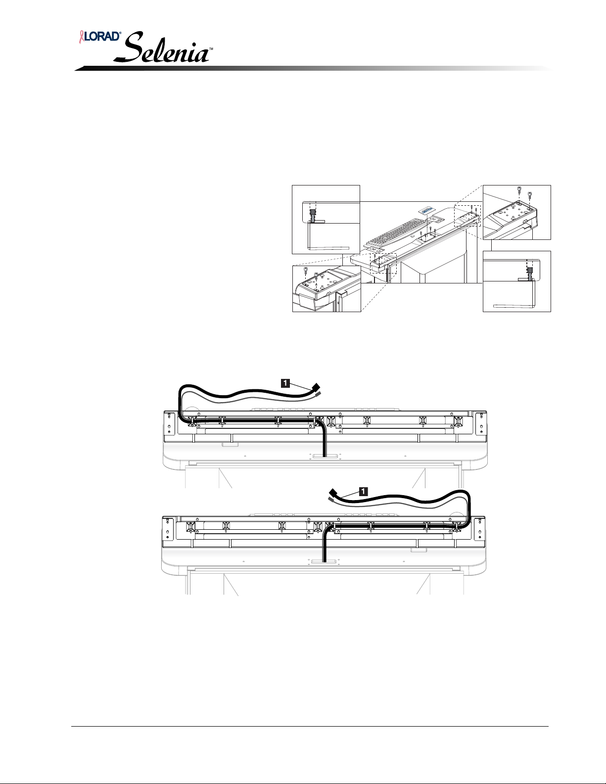
5.0 Optional Configuration
Standard Harness Routing
Optional Harness Routing
If the optional configuration is not used, skip to Section 3.0, p. 3-3.
5.1 Reversing the Direction of the Cable Harness
1. Remove the four screws
in the center of the base.
2. Remove both display
arm base clamps.
3. Flip the base to expose
the harness.
4. Cut the harness and
trackball cable ties.
5. Reverse the harness
direction.
See Figure 3-15.
Installation and Hardware Maintenance Manual
Chapter 3—AWS Installation with TechMate
Optional Configuration
Figure 3-14: Removing the Base
6. Insert new cable ties where you removed the old ones.
7. Install the harness in the swivel base and secure it with the new cable ties.
8. Reinstall the swivel base.
Figure 3-15: Harness Routing
MAN-00745 3-11
Legend for Figure 3-15
1. Selenia Display Connectors
Page 60
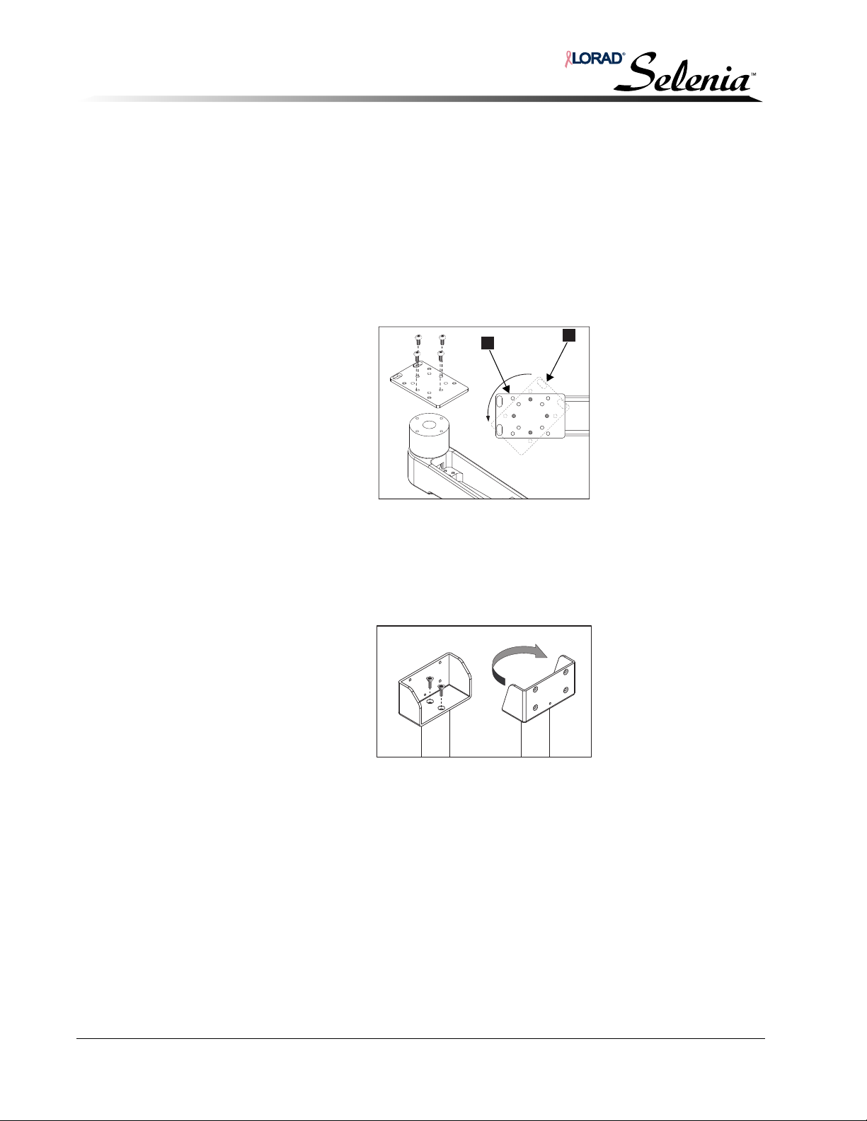
Installation and Hardware Maintenance Manual
Chapter 3—AWS Installation with TechMate
Optional Configuration
5.2 Left-Side Selenia Display Arm Configuration
Place the arm assembly on a stable, padded work surface.
5.2.1 Realigning the Cover on the Arm’s Post
1. With the arm and cover as shown in Figure 3-16 A, move the cover
counterclockwise to the position shown by the dotted line B.
2. Remove the four button-head screws holding the cover to the post.
3. Place the cover back to position A (ensuring the elongated holes in the cover are
facing the outside) and reinstall the four button-head screws.
A
Figure 3-16: Aligning the Arm Cover
5.2.2 Repositioning the Display Bracket (Totoku)
1. Remove the display bracket by removing the two screws.
2. Rotate the bracket 180° and reinstall the screws. See Figure 3-17.
B
Figure 3-17: Repositioning the Display Bracket
3-12 MAN-00745
Page 61
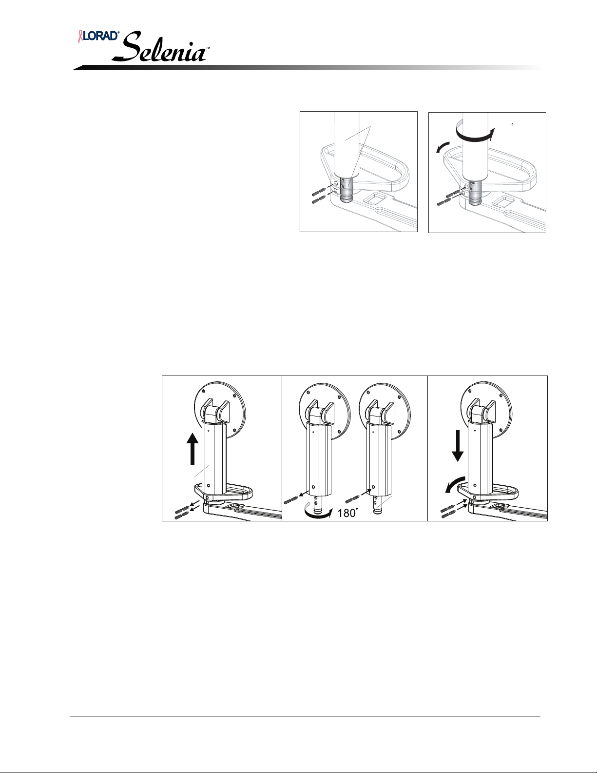
Installation and Hardware Maintenance Manual
Shaft
Handle
Shaft support
collar
Set screws(4)
Right-side Left-side
Support
Mount
Assembly
Support
Shaft
Support
Mount
Chapter 3—AWS Installation with TechMate
Optional Configuration
5.2.3 Repositioning and Realigning the Support Mount Assembly (Totoku)
1.
Remove the two
locking set screws,
and the two conical
set screws. It is not
necessary to
remove the
support
mount assembly.
Figure 3-18: Aligning the Shaft
2. Rotate the support mount assembly counterclockwise approximately 180°.
3. Align the holes in the support shaft with the holes in the collar and handle as
shown. Notice the holes are slightly staggered in this position.
4. Reinstall the two set screws. Ensure the screws are securely set.
180
5.2.4 Repositioning and Realigning the Support Mount Assembly (Barco)
1.
Remove the two locking set screws, and the two conical set screws
.
2. Remove the support mount and shaft from the arm.
Figure 3-19: Aligning the Shaft
3.
Remove the locking set screw, and the conical set screw
from the support mount.
4. Remove the support shaft from the support mount.
You may have to loosen the two socket-head cap screws at the bottom of the support
mount to remove the support shaft.
5. Rotate the support shaft counterclockwise approximately 180
°.
6. Secure the support shaft to the support mount with the previously removed set
screws.
MAN-00745 3-13
7. Align the holes in the support shaft with the holes in the collar and handle.
Notice the holes are slightly staggered in this position.
8. Reinstall the set screws; ensure the screws are securely set.
Page 62
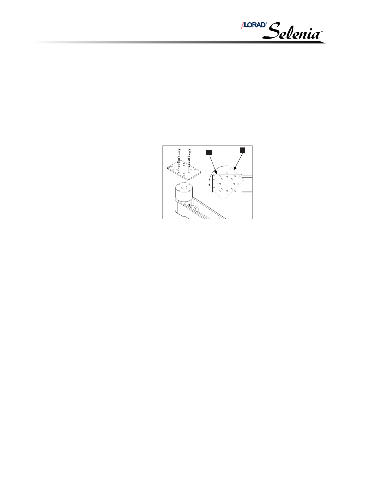
Installation and Hardware Maintenance Manual
A
Chapter 3—AWS Installation with TechMate
Optional Configuration
5.3 Right-Side TechMate Swivel-Arm Configuration
Place the arm assembly on a stable, padded work surface.
5.3.1 Realigning the Cover on the Arm’s Post
1. With the arm and cover as shown in Figure 3-20 A, move the cover
counterclockwise to the position shown by the dotted line B.
2. Remove the four button-head screws holding the cover to the post.
3. Place the cover back to position A (being sure the elongated holes in the cover
are facing the outside) and reinstall the four button-head screws.
B
Figure 3-20: Aligning the Arm Cover
4. Install the swivel arm on the base, and the display on the swivel arm. Refer to
Section 5.4, p. 3-15.
3-14 MAN-00745
Page 63
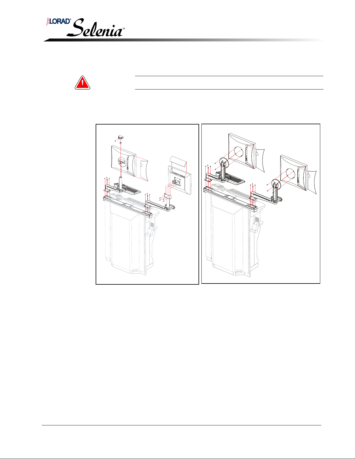
Installation and Hardware Maintenance Manual
Toto ku
Display
Barco
Display
Chapter 3—AWS Installation with TechMate
5.4 Displays, Swivel Arm, and Display Arm Attachment
Warning: Two people are required to safely perform this procedure.
1. Install the arms on the base, ensuring that, on each side of the unit, the elongated holes
are positioned toward the outside of the unit.
2. Install the displays on the arms.
Optional Configuration
Figure 3-21: Display, Swivel Arm, and Display Arm Attachment
MAN-00745 3-15
Page 64
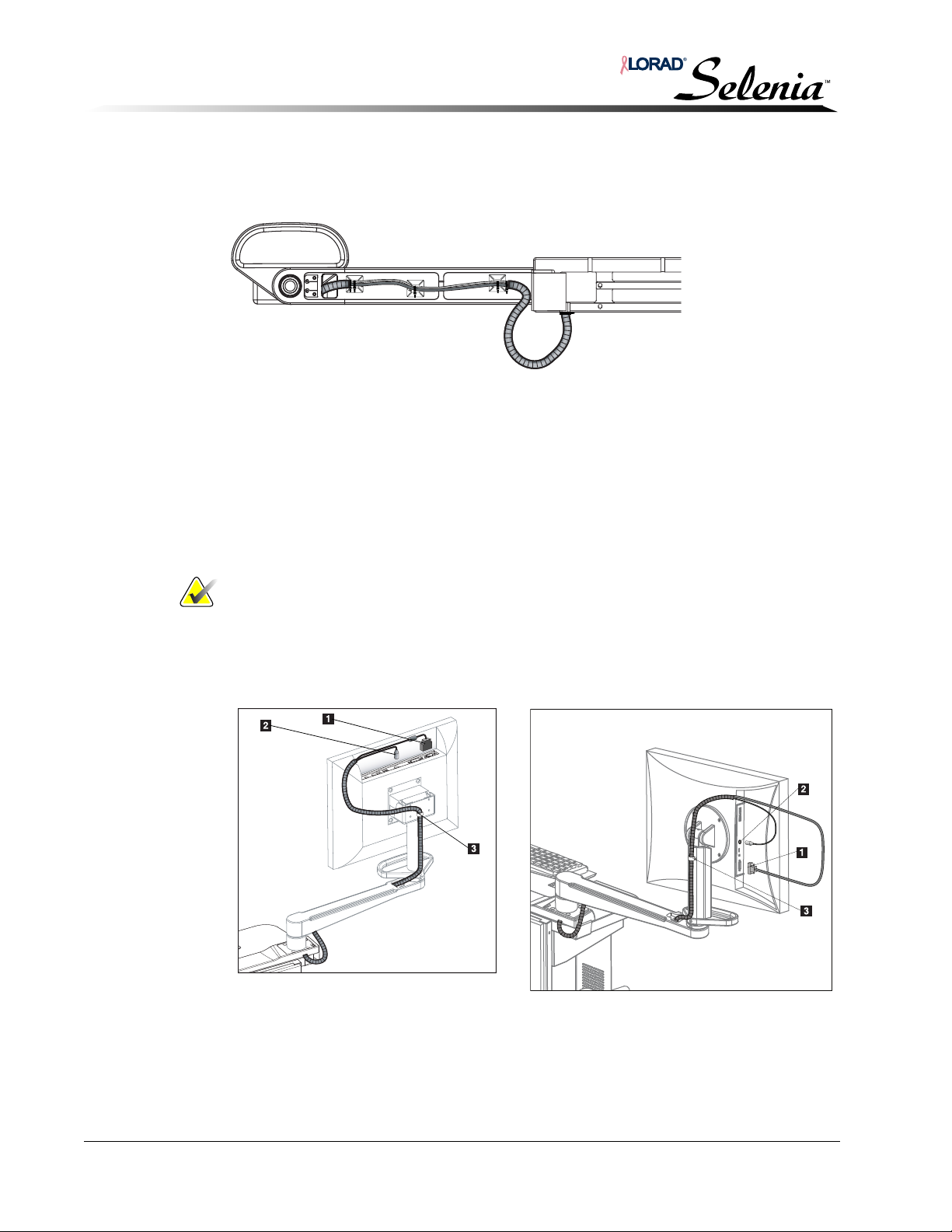
Installation and Hardware Maintenance Manual
Totoku
Display
Barco
Display
Chapter 3—AWS Installation with TechMate
Optional Configuration
5.4.1 Arm Harness Routing—Selenia
Referring to Figure 3-22, route the harness through the bottom of the arm, and
secure with cable ties.
Figure 3-22: Selenia Harness Routing Through Display Arm
5.4.2 Display Cables Attachment—Selenia
Refer to Figure 3-23.
1. Remove the cover (not shown) from the Display’s compartment providing access
to the connectors.
2. Connect the display power cable to the power connector on the display.
3. Connect the VGA(Totoku) or DVI (Barco) cable to the VGA/DVI port on the
upper rear of the display.
Note… Carefully position the VGA/DVI cable’s ferrite core so the cover closes
easily. Be sure the cover is fully latched.
4. Tighten the cable clamp.
5. Reinstall the cover on the Display’s compartment.
6. Ensure full range of motion on the Selenia swing-arm.
Legend for Figure 3-23
1. VGA/DVI Cable
2. Power Supply Cable
3. Cable Clamp
Figure 3-23: Selenia Display Connections
3-16 MAN-00745
Page 65
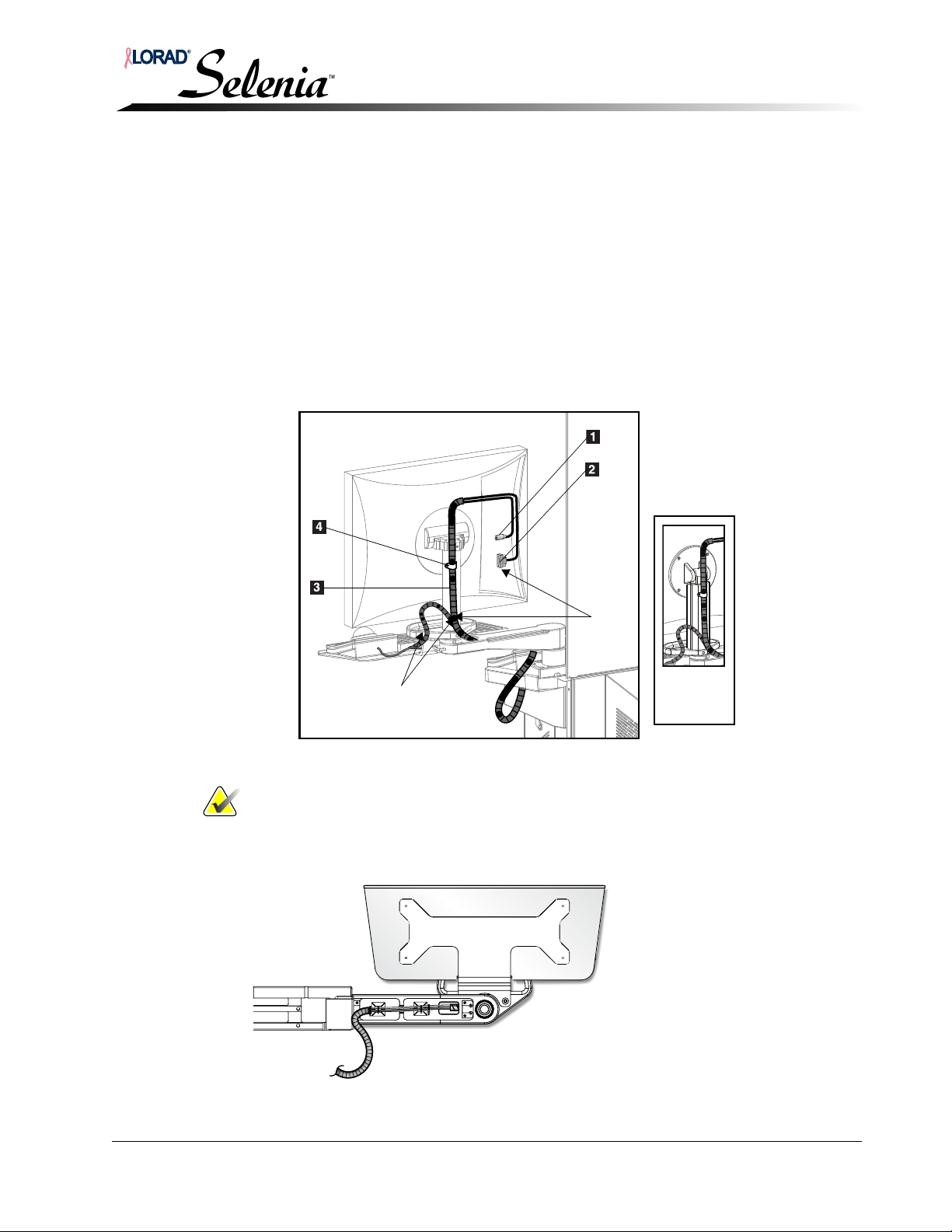
Installation and Hardware Maintenance Manual
25 in.
minimum
12 in.
New
Mount
Chapter 3—AWS Installation with TechMate
5.4.3 Display, and Arm Harness Routing—TechMate
1. Remove the AWS front cover:
a. Remove the two top screws securing the front cover to the front of the AWS.
b. Grasp the handles on the sides of the cover and slide upwards to free the
hooks from the slots in the front of the AWS frame.
c. Disconnect the cooling fans’ power cable, and the power switch cable from
the TechMate computer. Set the cover aside.
2. Reverse the display’s power module located beneath the TechMate computer; as
shown in the cable routing illustration; Figure 3-13, p. 3-9.
3. Remove the display’s cover (not shown).
4. Connect the display power cable, and the DVI cable; see Figure 3-24.
Optional Configuration
Legend for Figure 3-24
1. Power Cable
2. DVI Cable
3. Spiral Wrap
4. Cable Clamp
Figure 3-24: TechMate Display Connections
Note… Allow for service loops as shown in Figure 3-10.
5. See Figure 3-11, and route the harness through the bottom of the arm, and
secure with cable ties.
6. Continue with Section 4.1.4, p. 3-9.
Figure 3-25: TechMate Harness Routing Through Swivel Arm
MAN-00745 3-17
Page 66
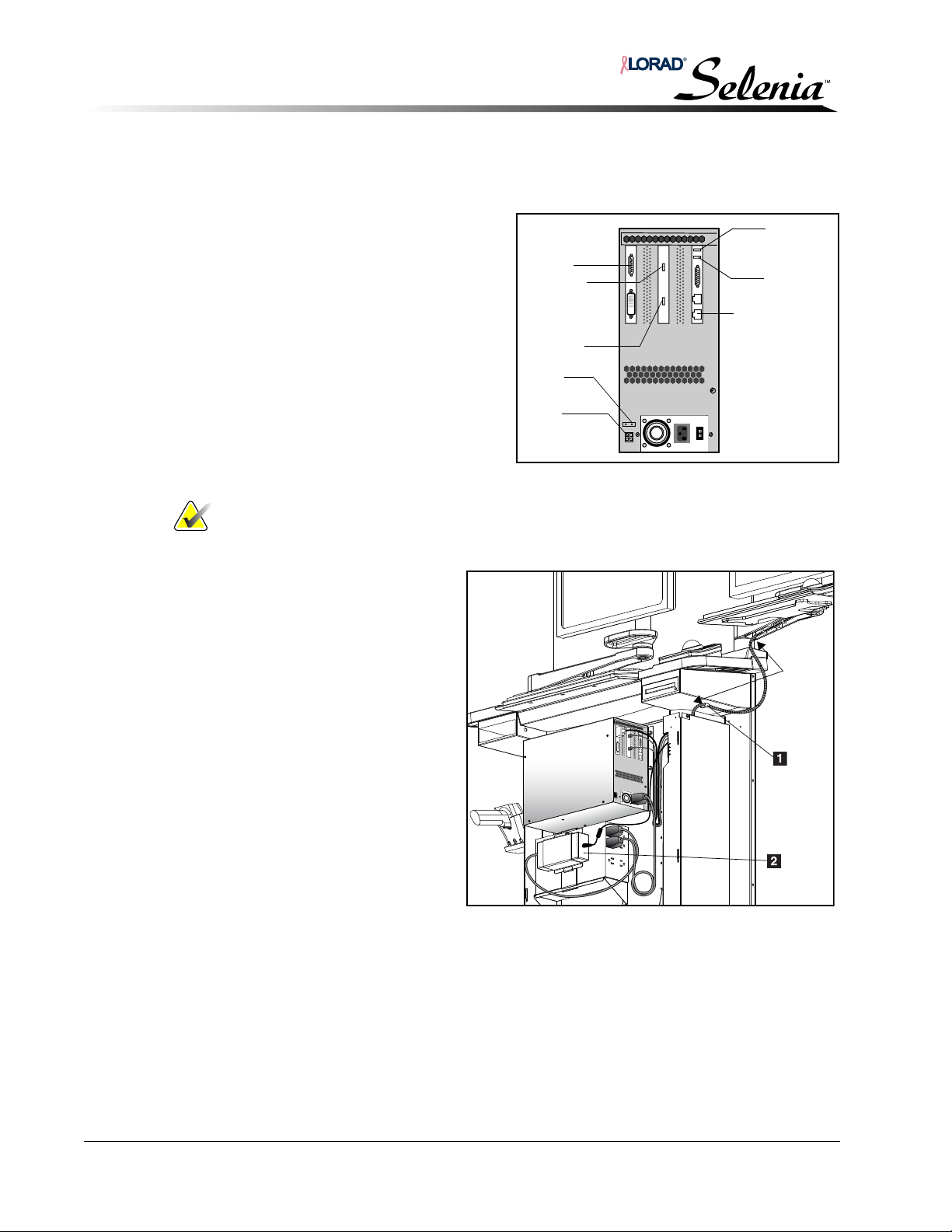
Installation and Hardware Maintenance Manual
To UPS
Dongl
e
Trackball
Keyboard
Display
‘Data Port’
Network Cable
Fan
Power
Switch
20 in.
minimum
Legend for Figure 3-13
1. Cable Clamp
2. Display Power Module
(reversed)
Chapter 3—AWS Installation with TechMate
Optional Configuration
5.4.4 Keyboard, and Trackball Cables Attachment—TechMate
For cable routing, see Figure 3-26, and Figure 3-13.
1. Position the TechMate
keyboard on the shelf and
connect the keyboard cable
to the TechMate computer.
2. Position the TechMate
trackball on the shelf and
connect the trackball cable to
the TechMate computer.
3. Dress the display, trackball
and keyboard cables, along
the right-side of the frame.
Figure 3-26: TechMate Connector Assignments
.Note… Allow for service loop as shown in Figure 3-13.
4. Ensure full range of
motion for the
TechMate swing-arm.
5. Secure the cable
harness to the rightside of frame.
6. Reinstall the cover on
the display’s rear
compartment.
7. Connect the cooling
fans’ power cable,
and the power switch
cable to TechMate
computer.
8. Reinstall the AWS
front cover reversing
the steps described in
Section 5.4.3, p. 3-
17.
3-18 MAN-00745
Figure 3-27: TechMate Harness Routing
Page 67
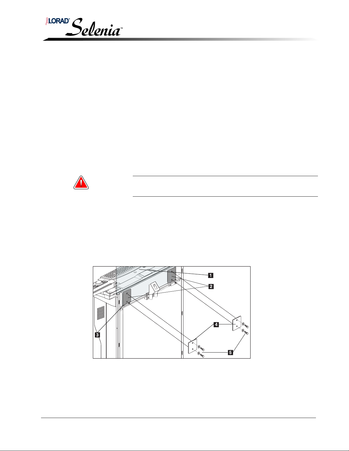
Installation and Hardware Maintenance Manual
6.0 Selenia Network Cable Installation
1. Connect the network cable to the computer; see Figure 3-5, p. 3-4.
2. Following the fiber optic cable, route the network cable through either the right or left
cable clamp at the rear of the unit.
3. Connect the network cable to the site network.
7.0 TechMate Network Cable Installation
The TechMate network cable is routed through a trough in the base of the unit and then
clamped down with the left clamp for shipment.
1. The cable exits the rear left of the unit, release one of the bolts on the clamp and rotate
the clamp to release the cables.
2. Connect the network cable to the site network.
8.0 Installing the Radiation Shield
Chapter 3—AWS Installation with TechMate
Selenia Network Cable Installation
Warning: The Radiation Shield is tempered glass and may shatter if dropped
or overstressed.
1. Lift the radiation shield and place it on the support shelf.
2. Attach the shield to the front shield support, with the logo facing the patient.
3. Align the holes in the shield with the threaded holes in the AWS rear frame.
4. Position the two protective plates over the shield mounting holes.
5. Secure the plates and the shield to the AWS rear frame using the four supplied bolts and
lock washers.
6. Tighten the bolts just enough to compress the lockwashers.
Figure 3-28: Selenia Radiation Shield Installation
Legend for Figure 3-28
1. Radiation Shield
2. Front Shield Support (part of sheet metal)
3. Support Shelf
4. Protective Plate (2)
5. Bolts and Lockwashers (4)
MAN-00745 3-19
Page 68
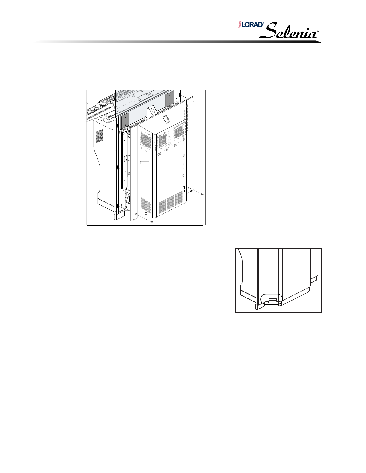
Installation and Hardware Maintenance Manual
Chapter 3—AWS Installation with TechMate
Installing the AWS Rear Cover
9.0 Installing the AWS Rear Cover
1. Position the hooks on the rear cover so that they align with the slots in the rear frame.
2. Plug in the cooling fan harness; see Figure 3-29.
Figure 3-29: Cooling Fan Harness
3. Make sure all cabling is within the cover notches.
4. Insert the hooks into the slots, then slide the rear
cover down.
5. Secure the cover in place using two screws.
6. Turn on the AWS circuit breaker. Observe any
possible electrical malfunction.
Figure 3-30: Cover Notches for Cabling
3-20 MAN-00745
Page 69
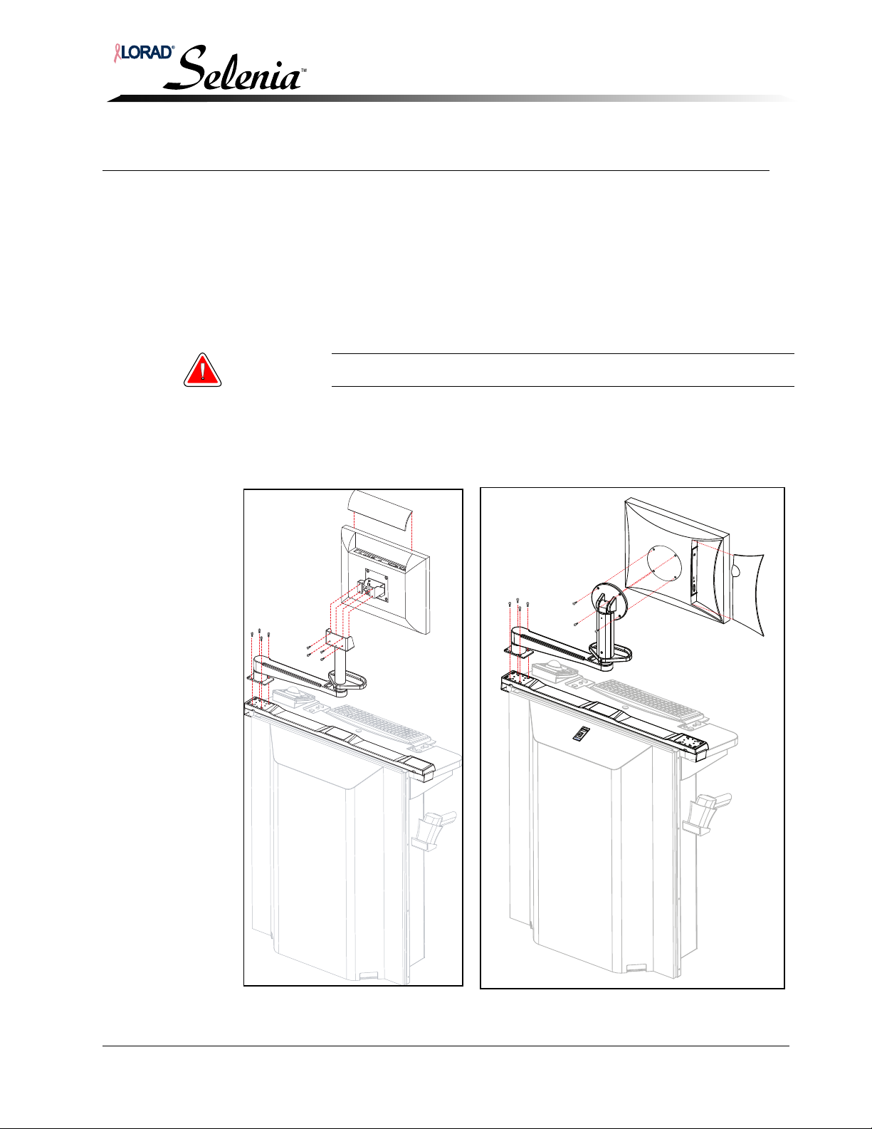
Installation and Hardware Maintenance Manual
Totoku
Display
Barco
Display
Chapter 4—AWS Installation without TechMate
Standard Configuration
Chapter 4—AWS Installation without TechMate
1.0 Standard Configuration
In the standard configuration, the Selenia display arm and the trackball are installed on the
right side of the AWS. Optionally, the Selenia display arm and/or the trackball is installed on
the left side of the AWS.
Refer to “Optional Configuration” on p. 4-6 for details.
1.1 Display and Display Arm Attachment
Warning: Two people are required to safely perform this procedure.
1. Install the arm on the base, ensuring that, the elongated holes are positioned toward the
outside of the unit.
2. Install the display on the arm.
Figure 4-1: Display and Display Arm Attachment
MAN-00745 4-1
Page 70
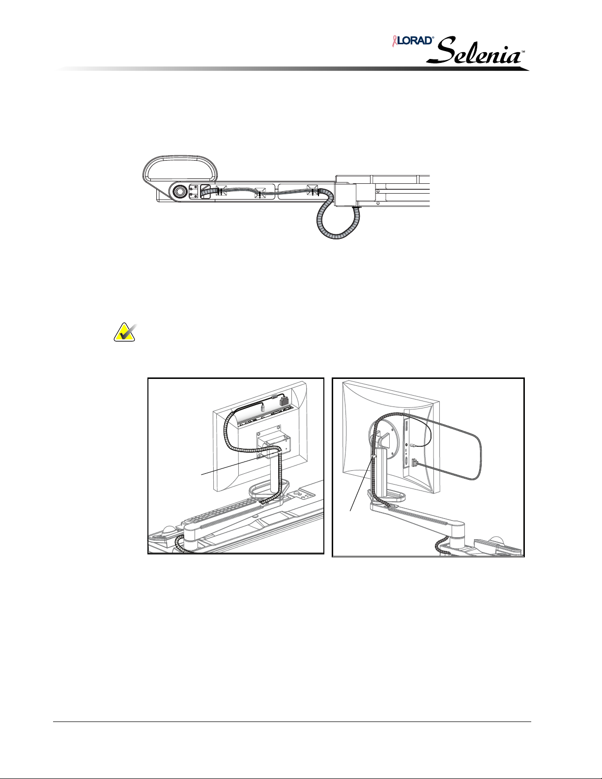
Installation and Hardware Maintenance Manual
Cable
Clamp
Toto ku
Display
Cable
Clamp
Barco
Display
Chapter 4—AWS Installation without TechMate
Display Harness Routing
1.2 Arm Harness Routing
Route the harness from underneath through the bottom of the Selenia Display Arm, and
secure with cable ties.
Figure 4-2: Selenia Harness Routing Through Display Arm
2.0 Display Harness Routing
1. Connect the display cables as shown in Figure 4-3.
Note… Be sure the cover closes easily, and the cover is fully latched.
2. Tighten the cable clamp.
Figure 4-3: Selenia Display Connections
4-2 MAN-00745
Page 71
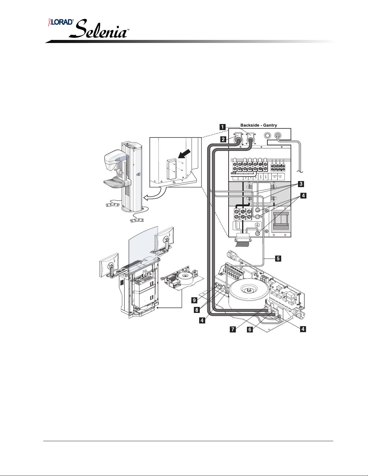
Installation and Hardware Maintenance Manual
Chapter 4—AWS Installation without TechMate
Gantry to Acquisition Workstation Interconnections
3.0 Gantry to Acquisition Workstation Interconnections
3.1 Power
1. At the rear of the AWS, connect one end of the power cable to the Power Out to Gantry
receptacle (#8, Figure 4-4) on the AWS Power Distribution Assembly.
2. Connect the power cable to the J
connector panel.
3. Make the remaining connections as shown in Figure 4-4.
2 Acquisition Power receptacle (#2,) on the Gantry
.
Figure 4-4: Gantry to Acquisition Workstation Interconnections
Legend for Figure 4-4
1. J2 Acquisition Power receptacle
2. J1 Acquisition Data receptacle
3. Data and Power Cable Ground Wires
4. Ground Studs
5. Equipotential Ground Wire
6. Data Receptacle
7. Power Out to Brick and Gantry Control
8. Brick Power Fuses (2A FB, 250VAC)
9. Input Power Receptacle (AWS)
4. Connect one end of the AWS input power cord to the AWS input power receptacle
(#9, Figure 4-4) on the AWS Power Distribution Assembly and plug the other end into
site power.
MAN-00745 4-3
Page 72
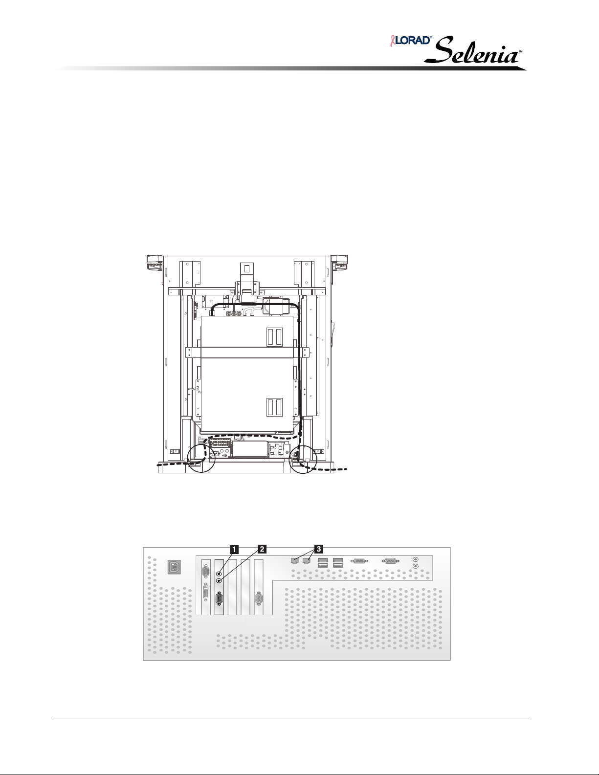
Installation and Hardware Maintenance Manual
Legend for
Figure 4-6
1. Rx—Blue
Wire
2. Tx—Orange
Wire
3.
Network
Cable
Chapter 4—AWS Installation without TechMate
Gantry to Acquisition Workstation Interconnections
3.2 Fiber Optics
The fiber optic cables are connected between the Gantry and the AWS computer.
At the AWS:
1. Locate the cable clamp at the rear of the AWS below the cover handle. An identical
clamp is located on the opposite side of the AWS. All the AWS cabling exits from the
cutouts in the rear cover.
2. Route the fiber optic cable into the AWS as shown in Figure 4-5. The dotted line in the
illustration shows alternate entry paths into the AWS. Use the existing cable clamps
along each path for cable support.
3. Continue to route the cable into the AWS computer.
Figure 4-5: Fiber Optic Cabling, Acquisition Workstation
4. Connect the fiber optic cable into the termination points at the rear of the computer—
Figure 4-6.
Figure 4-6: Fiber Optic and Network Cable Termination Points
5. Allowing for a service loop, secure the wiring with cable ties.
4-4 MAN-00745
Page 73
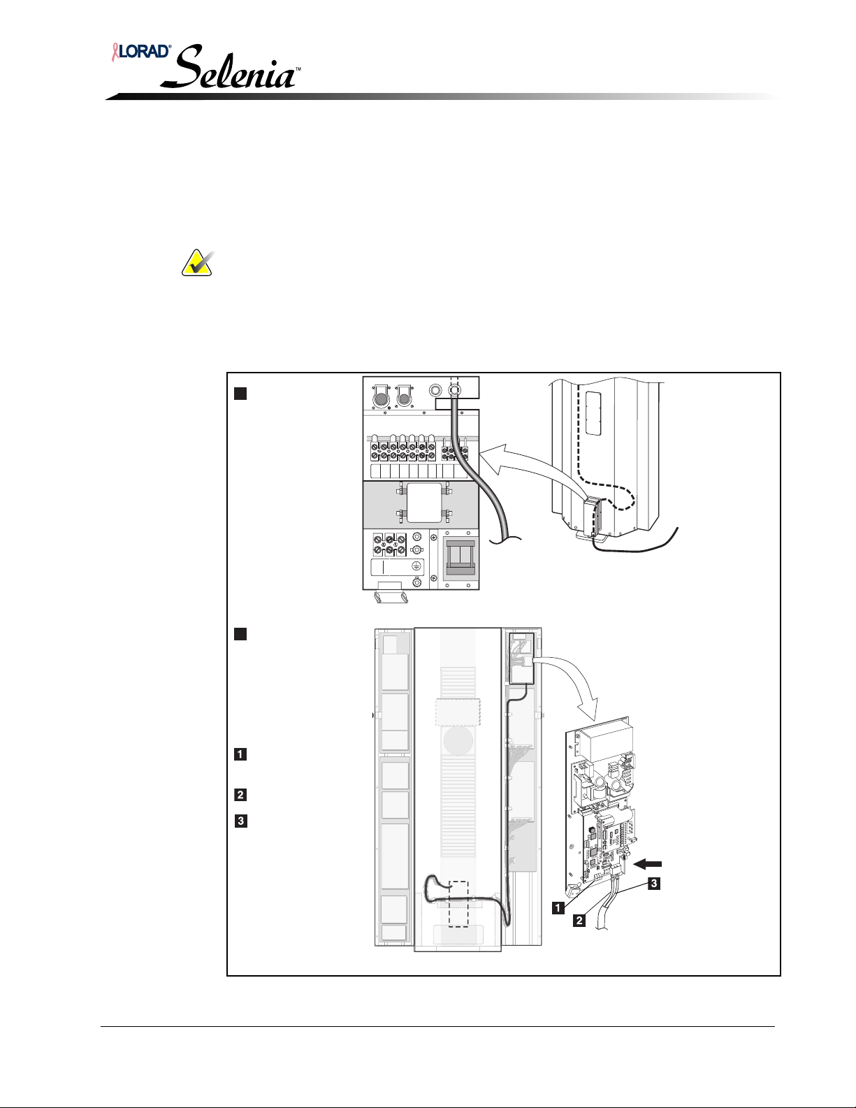
Installation and Hardware Maintenance Manual
A
Entry
B
Routing and
Termination
(Rear view of
the Gantry)
(Front view of
the Gantry)
Three LEDs:
1 red, 2 green
Orange Wire
Blue Wire
Chapter 4—AWS Installation without TechMate
Gantry to Acquisition Workstation Interconnections
At the Gantry
1. Route the cable into the Gantry through the rear lower access panel. A cutout on the
power panel allows entry into the Gantry mainframe. See inset ‘A’ below.
2. Following the Main Harness inside the Gantry mainframe, route the fiber optic cable up
to the Brick. See inset ‘B’ below. Connect the cable to the Brick.
Note… It is possible to install the fiber optic cable incorrectly (reversed). If they are
reversed, the red LED is on. When correct, the red LED is off, the right green
LED is on, and the center LED blinks.
3. Allowing for a ‘service loop’, secure the wiring with cable ties.
4. Secure the fiber optic cable to the bulk cabling from the Gantry to the AWS.
5. Reattach the lower rear panel and turn on the wall and Gantry circuit breakers.
CONSOLE
J3
RIGHT
FOOTSW
J2
J1
CONSOLE
POWER
DATA
J4
LEFT
FOOTSW
N
200V~
POWERONX-RAY
208V~
220V~
ON
230V~
240V~
Figure 4-7: Fiber Optic Cabling, Gantry
MAN-00745 4-5
Page 74
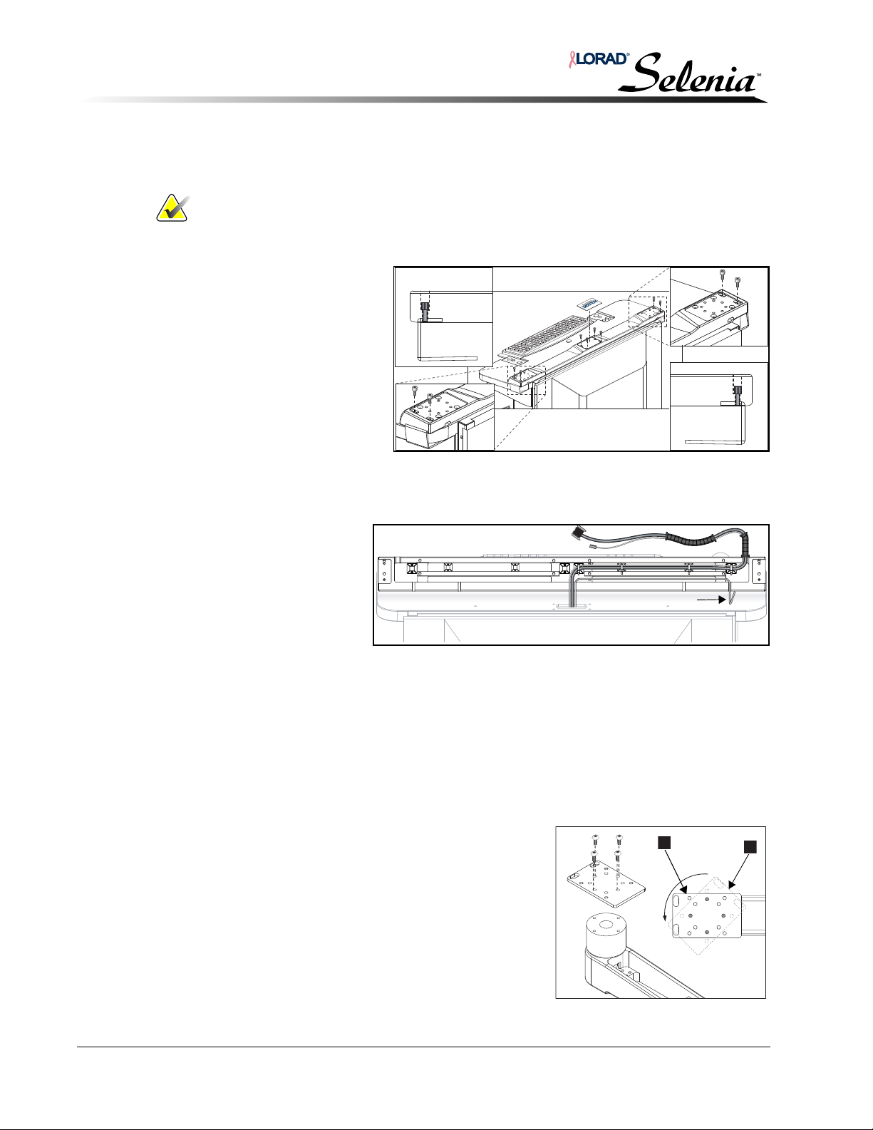
Installation and Hardware Maintenance Manual
Trackball Cable
A
B
Chapter 4—AWS Installation without TechMate
Optional Configuration
4.0 Optional Configuration
Note… This procedure mounts the Selenia Display Arm, display, and trackball on
the left-hand side of the AWS.
4.1 Remove the Base
1. Remove the label and
the four screws in the
center of the base.
2. Remove both display
arm base clamps.
3. Rotate to expose the
harness under the base.
4. Cut the harness and
trackball cable ties.
4.2 Reconfigure the Base Wiring
Reroute the harness and
trackball cable for left
side configuration.
4.3 Replace the Base
1. Position the base at the rear of the AWS.
2. Reinstall the four screws and the display arm base clamps.
3. Replace the label.
4.4 Realigning the Cover on the Arm’s Post
1. With the arm and cover still fastened as shown in
Figure 4-10 A, move the cover counterclockwise to
the position shown by the dotted line B.
2. Remove the four button-head screws holding the
cover to the post.
3. Place the cover back to position A (being sure the
elongated holes in the cover are facing the outside)
and reinstall the four button-head screws.
Figure 4-8: Removing the Base
Figure 4-9: Left-Side Base Wiring
Figure 4-10: Aligning the Arm Cover
4-6 MAN-00745
Page 75
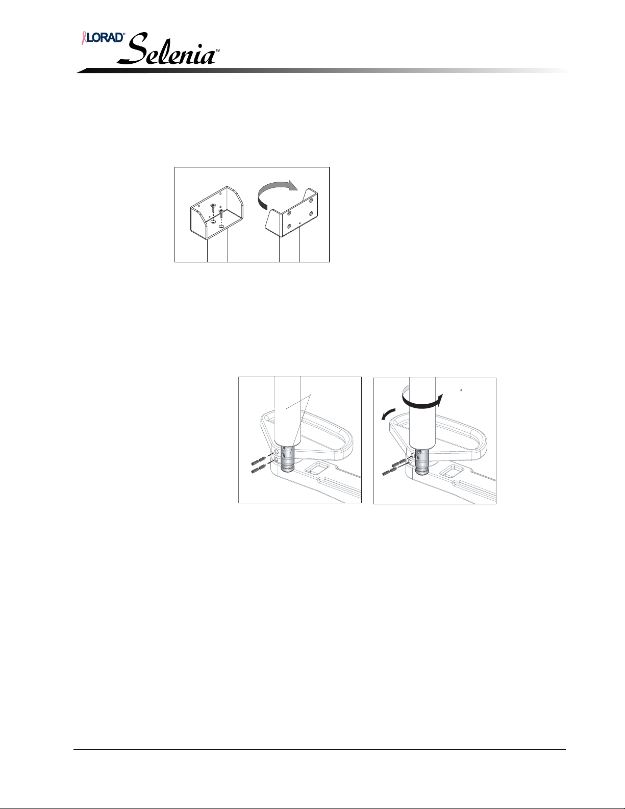
Installation and Hardware Maintenance Manual
Shaft
Handle
Shaft support
collar
Set screws(4)
Right-side Left-side
Support
Mount
Assembly
Chapter 4—AWS Installation without TechMate
Optional Configuration
4.5 Repositioning the Totoku Display Bracket
1. Remove the display bracket by removing the two screws.
2. Rotate the bracket 180° and reinstall the screws. See Figure 4-11.
Figure 4-11: Repositioning the Display Bracket
4.6 Repositioning and Realigning the Support Mount Assembly
4.6.1 Totoku
1.
Remove the two locking set screws, and the two conical set screws. It is not
necessary to remove the
2. Rotate the support mount assembly counterclockwise approximately 180°.
3. Align the holes in the support shaft with the holes in the collar and handle as
shown. Notice the holes are slightly staggered in this position.
4. Reinstall the two set screws. Ensure the screws are securely set.
support mount assembly.
180
Figure 4-12: Aligning the Shaft
MAN-00745 4-7
Page 76
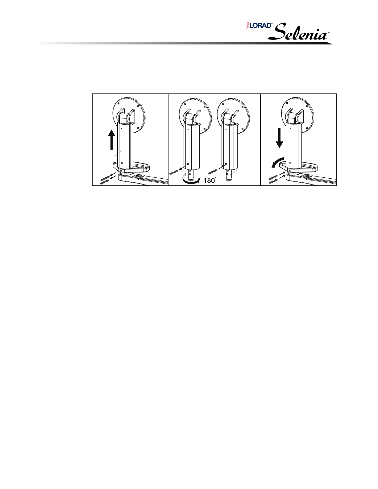
Installation and Hardware Maintenance Manual
Support
Shaft
Support
Mount
Chapter 4—AWS Installation without TechMate
Optional Configuration
4.6.2 Barco
1.
Remove the two locking set screws, and the two conical set screws
2. Remove the support mount and shaft from the arm.
Figure 4-13: Aligning the Shaft
.
Remove the locking set screw, and the conical set screw
3.
from the support mount.
4. Remove the support shaft from the support mount.
You may have to loosen the two socket-head cap screws at the bottom of the
support mount to remove the support shaft.
5. Rotate the support shaft counterclockwise approximately 180
°.
6. Secure the support shaft to the support mount with the previously removed set
screws.
7. Align the holes in the support shaft with the holes in the collar and handle.
Notice the holes are slightly staggered in this position.
8. Reinstall the set screws; ensure the screws are securely set.
4-8 MAN-00745
Page 77
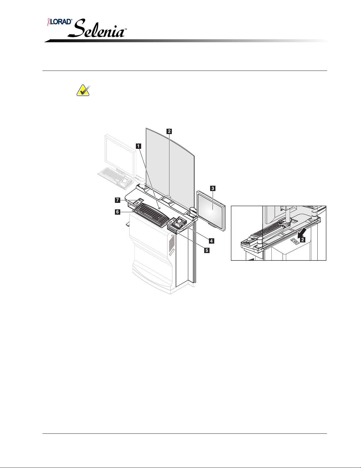
Installation and Hardware Maintenance Manual
Chapter 5—Startup, Shutdown, and Functional Tests
Acquisition Workstation Controls and Display
Chapter 5—
Startup, Shutdown, and Functional Tests
Note… Refer to the Selenia Software Operator’s Manual and Hardware Operator’s
Manual for detailed information about operating the Selenia.
1.0 Acquisition Workstation Controls and Display
Legend for Figure 5-1
1. Emergency Off Switch
2. Circuit Breaker (at rear of AWS)
3. Selenia Display
4. Selenia Trackball
5. CD-RW Drive
6. Selenia Keyboard
7. Selenia Power On Button
Figure 5-1: The AWS Controls
MAN-00745 5-1
Page 78
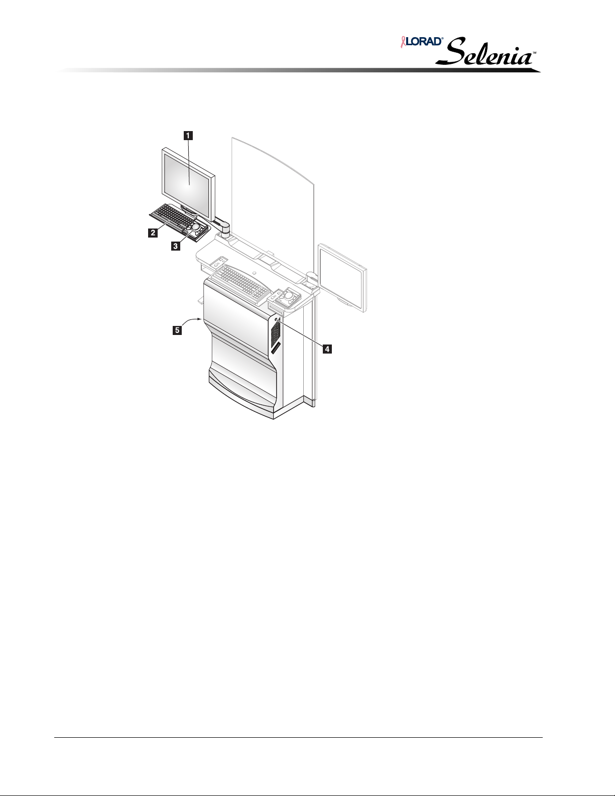
Installation and Hardware Maintenance Manual
Chapter 5—Startup, Shutdown, and Functional Tests
TechMate Controls and Display
2.0 TechMate Controls and Display
Legend for Figure 5-2
1. TechMate Display
2. TechMate Keyboard
3. TechMate Trackball
4. Power Button for TechMate
5. Reset Button for TechMate
Figure 5-2: The TechMate Controls
3.0 Initial Startup Procedures
At this point in the Selenia installation procedures:
• Both the Gantry and AWS are permanently mounted in position.
• All power and applicable accessory connections are complete.
• The Image Receptor is installed.
• The footswitch(es) are installed.
• Additional system components (for example, Hard Copy Film Printer) are installed.
5-2 MAN-00745
Page 79
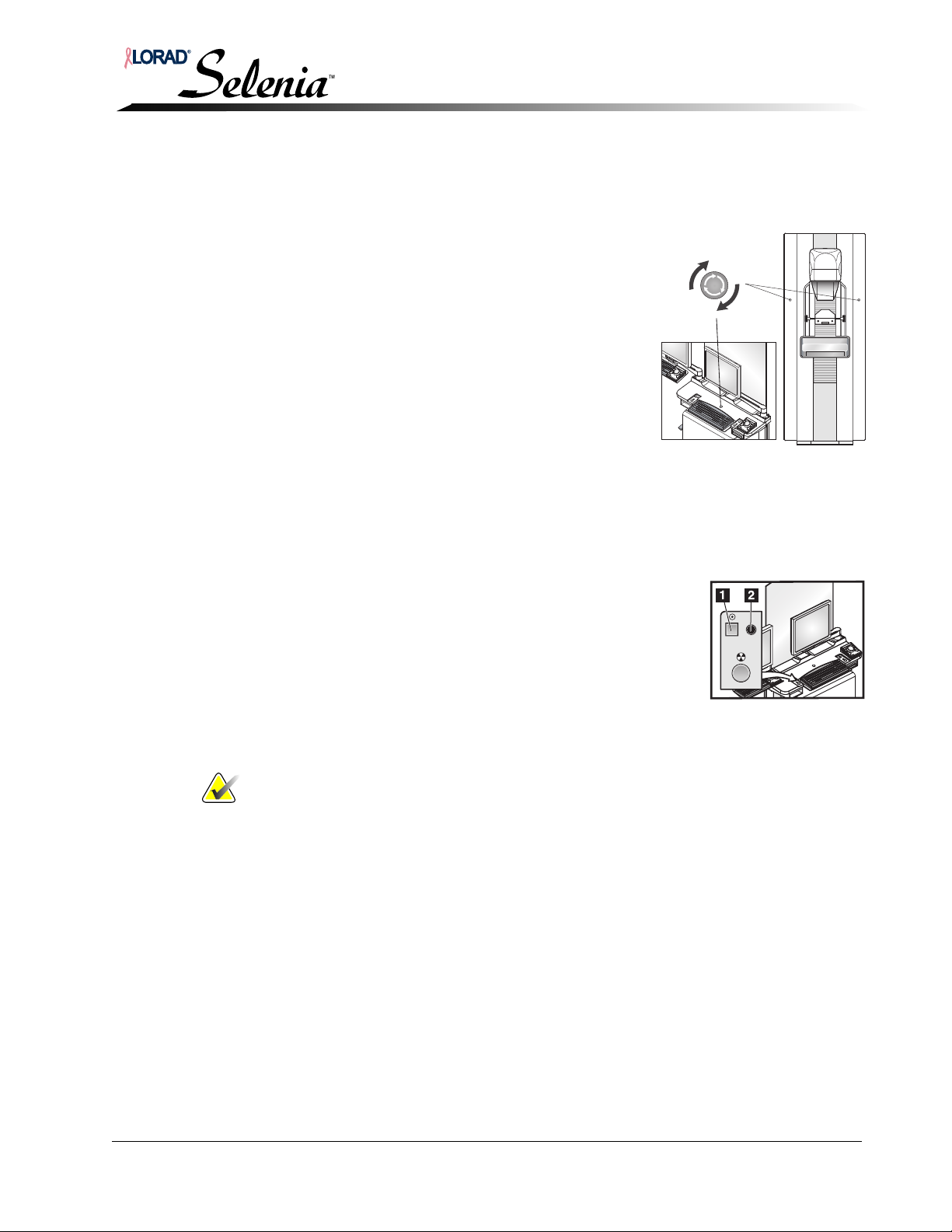
3.1 Pre-Startup Checks
Figure 5-3: Emergency Off
Switches
Perform the following pre-startup checks before applying power to the system for the first
time following installation:
1. Verify that:
a. Primary (source) power circuit breaker is On.
b. Circuit breaker on the rear of the Gantry is On.
c. Turn on UPS (Selenia) see Figure 5-4, p. 5-4.
d. All three Emergency Off switches are reset (two on
the Gantry, one on the AWS) see Figure 5-3.
2. Inspect the overall integrity of the mammography unit
for open or loose panels, missing hardware, and signs
of damage.
3. Inspect the radiation shield for chips, cracks, breaks,
and secure attachment.
4. Be sure the room is clear of obstructions.
5. Correct all discrepancies before starting the system.
Installation and Hardware Maintenance Manual
Chapter 5—Startup, Shutdown, and Functional Tests
Initial Startup Procedures
3.2 Turning On the System
3.2.1 Selenia AWS
1. Press the Power On button (small black button, #1, on
the left keypad) momentarily to start the system.
2. A green LED, #2, illuminates to indicate power is on.
3. Wait for the computer to start.
The system initializes and runs the diagnostic tests.
This may take several minutes. The temperature of the
Selenia Detector is critical for image quality. To
stabilize its temperature, the detector should be on for at least 1 hour (warm up)
before patient exposure.
Notes… If during the internal checks, the system detects a fault condition, a message
displays, and startup is suspended until the problem is remedied.
3.2.2 TechMate
1. Turn on UPS (TechMate), see Figure 5-5, p. 5-4.
2. Start the TechMate by pressing the TechMate power button on the upper right
side of the Workstation front cover. See Figure 5-2, p. 5-2.
3. Refer to SecurView
User information.
RT
documentation for additional TechMate Installation and
MAN-00745 5-3
Page 80
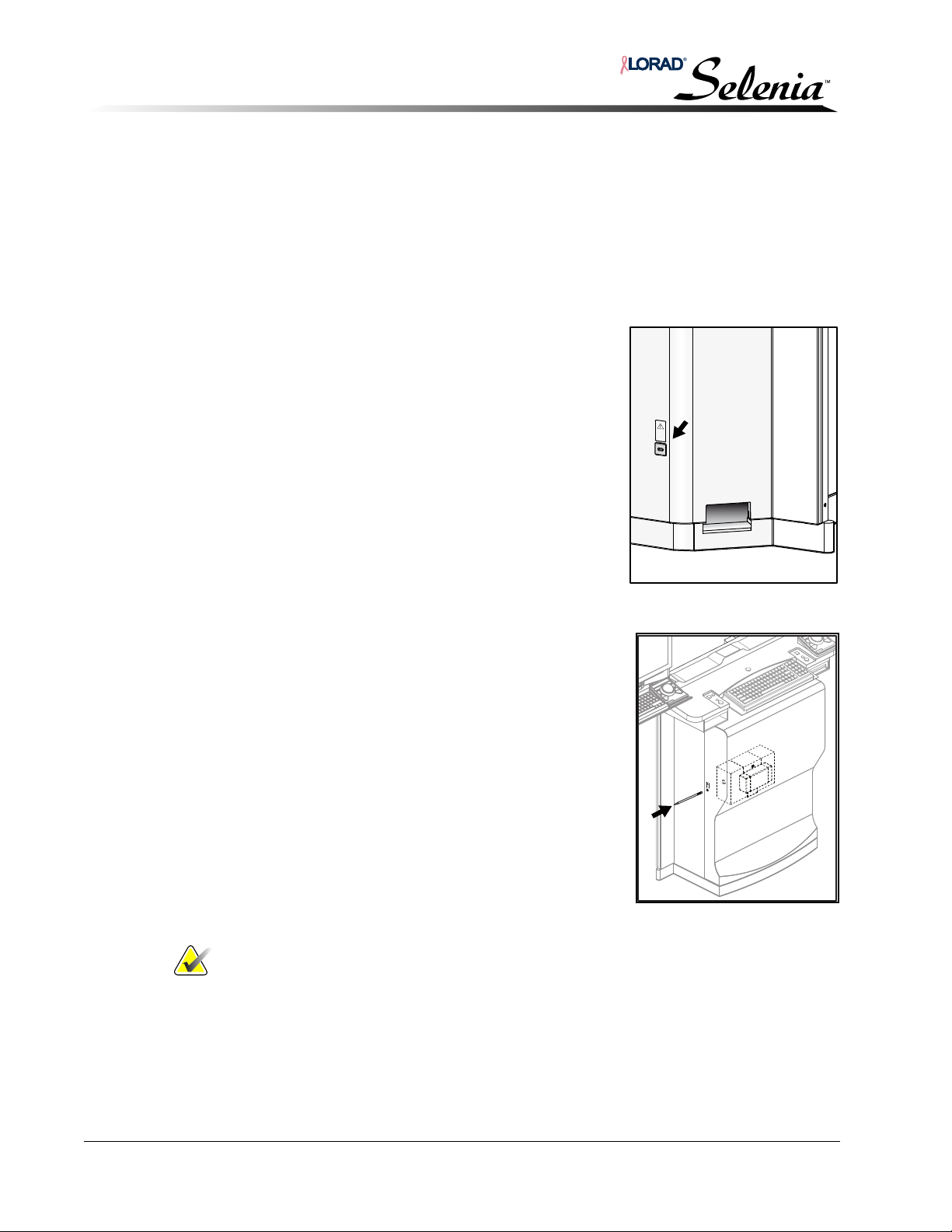
Installation and Hardware Maintenance Manual
Chapter 5—Startup, Shutdown, and Functional Tests
Initial Startup Procedures
3.3 Resetting the UPS
3.3.1 System Power Is Turned Off
If the Acquisition Workstation does not respond to the On button, the
Uninterruptible Power Supply (UPS) may need to be reset. For example: If power is
removed from the Acquisition Workstation (such as power source disconnected or
circuit breaker switched off) and then re-applied, the UPS may not automatically
respond.
To reset the Selenia UPS:
See Figure 5-4.
1. Locate the UPS button at the lower right of the
back panel.
2. Press down and hold the button to press the
reset button on the UPS. The UPS chirps.
3. Press the button again and listen for a second
chirp.
4. Start the Acquisition Workstation normally.
U
P
S
L
B
L
0
0
3
4
3
Figure 5-4: Resetting the Selenia UPS
To reset the TechMate UPS:
See Figure 5-5.
1. Locate the access hole in the middle of the left
side of the front cover. This hole is aligned with
the Power button on the UPS.
2. Insert the eraser-end of a pencil into the hole to
press the button on the UPS. The UPS chirps.
U
P
S
L
B
L
0
0
3
4
3
3. Press the button again and listen for a second
chirp.
4. Start the TechMate normally.
Figure 5-5: Resetting the TechMate UPS
Notes… If the above procedure fails to reset the UPS, the circuit breaker located at
the right side of the TechMate UPS may have tripped. Remove the front
cover (refer to Chapter 3, Section 4.1.4, p. 3-9). Determine if the equipment
plugged into the protection outlets are creating an overload, then reset the
circuit breaker by pushing it back in.
5-4 MAN-00745
Page 81

3.3.2 All Power Is Off
R
VNLV–
FL
I
MaxL
-------------------------=
If the site looses power, the UPS begins to chirp. This is an expected alarm indicating
that the power is off.
1. Shut down the AWS if it is still on.
2. To turn off the beeping noise, follow the appropriate procedure above, but press
the button only once.
3. Press it again when the power returns.
4. Start the Acquisition Workstation normally.
4.0 Test Ground Impedance
Equipment Required:
DVM—to measure AC voltage
Inductive Ammeter—capable of measuring at least 30 A AC
Measure Voltage/Current:
1. Measure the no-load voltage.
2. Measure the full-load voltage:
a Click on the Non-Imaging Mode.
b Cover the Image Receptor with lead.
c Perform a full-exposure test in manual mode—32 kV, at 200 mAs.
Installation and Hardware Maintenance Manual
Chapter 5—Startup, Shutdown, and Functional Tests
Test Ground Impedance
Calculate the ground impedance using the following formula:
Where:
R = Ground Impedance
V
= Voltage at no load
NL
V
= Voltage at full load
FL
I
= Current at full load
MaxL
Ground impedance must be no more than:
0.20
Ω
at 208, 220, 230, 240 V~TAP
0.16
Ω
at 200 V~TAP
If results are higher, stop work and contact the building electrician to repair the ground
impedance.
MAN-00745 5-5
Page 82
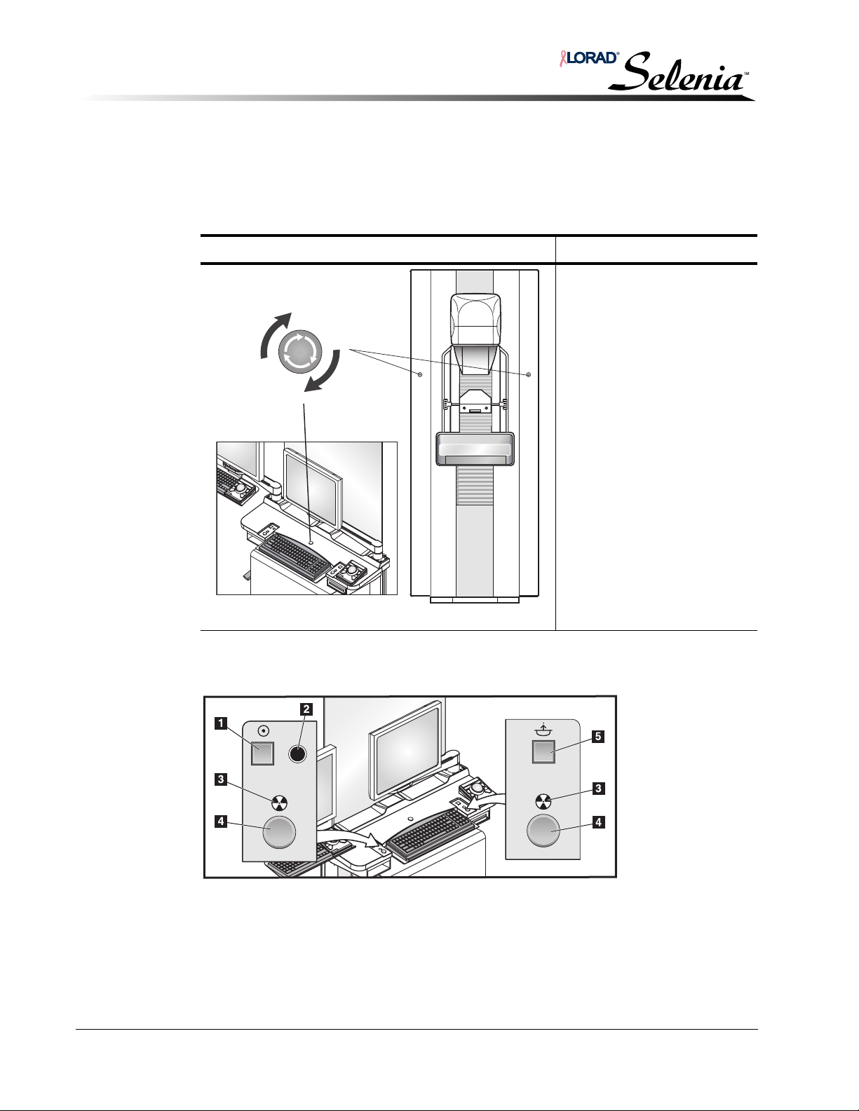
Installation and Hardware Maintenance Manual
Chapter 5—Startup, Shutdown, and Functional Tests
Controls and Displays
5.0 Controls and Displays
Each of the operator controls on the C-arm, Tubehead, and Footswitch must be tested to
verify the unit’s electromechanical functions
5.1 Emergency Off Switches
Location of Emergency Off Switches Description
There are three Emergency Off
switches on the Selenia, one
on each side of the Gantry and
one on the AWS.
Press any of the Emergency
Off switches to immediately
remove power to the gantry.
Turn the Emergency Off switch
one-quarter turn to reset the
switch.
To restart the system after
using an Emergency Off
switch, refer to “Emergency
Off Switches” on p. 5-18.
Figure 5-6: Emergency Off Switches
5.2 Acquisition Workstation Keypads
Keypads provide power, x-ray, and Compression Release functions.
Figure 5-7: Location of Acquisition Workstation Controls
Legend for Figure 5-7
1. On button.
2. On indicator light.
3. X-ray Indicator lights
on both panels.
4. X-ray buttons on both panels, one on each side of the keyboard.
Press them both simultaneously to make an exposure and hold for
the duration of the tone.
5. Compression Release button.
5-6 MAN-00745
Page 83
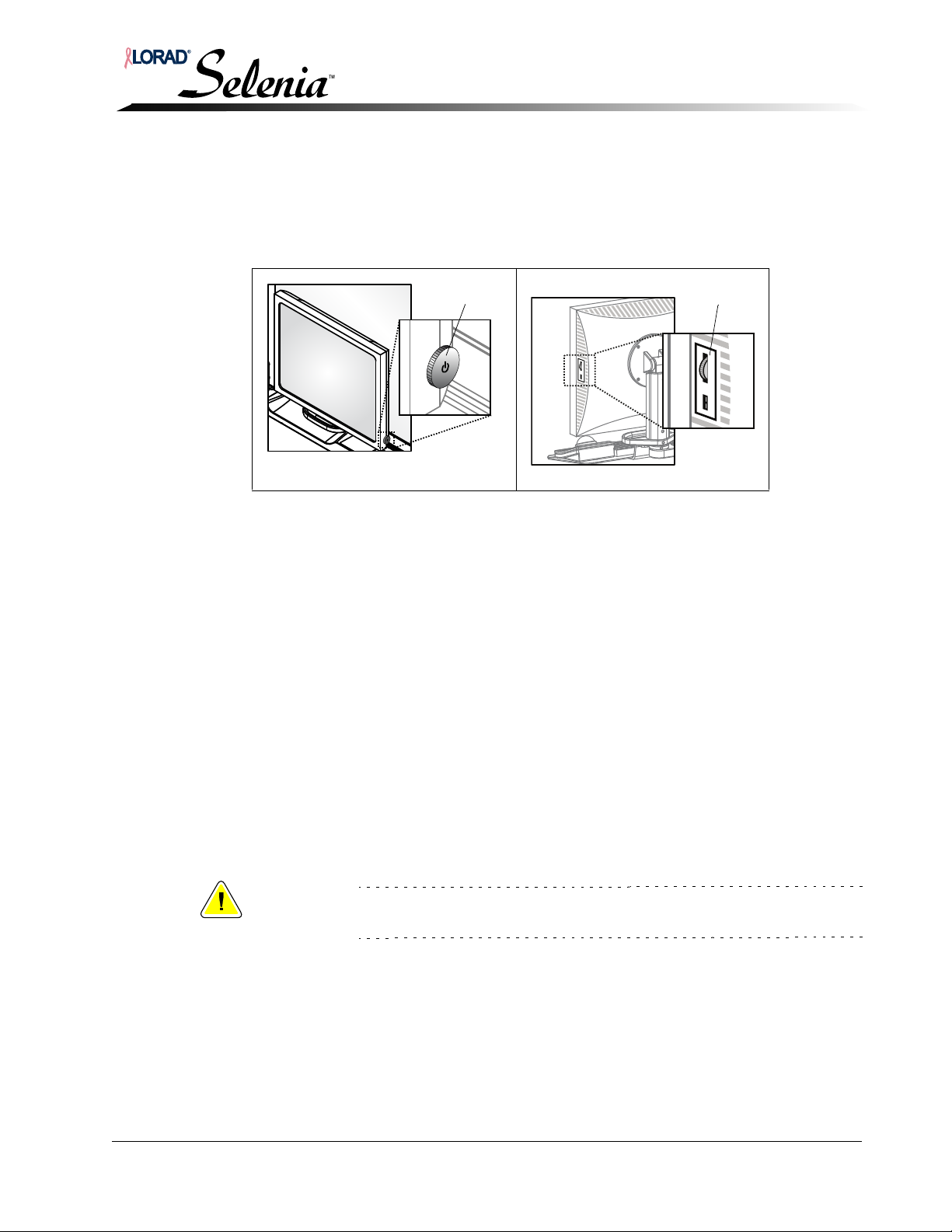
5.3 Selenia Display
Control Dial
Totoku
Display
Control Dial
Barco
Display
Press the Control Dial to turn on the display. A green indicator light shows power is on.
To turn off the display, press and hold the button for at least 1 second until the LED is off.
The display can be left on. It turns off when the system is turned off.
Installation and Hardware Maintenance Manual
Chapter 5—Startup, Shutdown, and Functional Tests
Controls and Displays
Figure 5-8: Flat Screen Display
5.3.1 Adjusting the Display
The Control Dial can be pressed like a push button and rotated like a knob.
Navigation through the menus to make adjustments, and to change values can be
made using the on-screen display (OSD) menu, activated by rotating the control
dial. To enter a menu:
1. Rotate dial to the desired menu
2. Press the dial to select
3. Rotate the dial to change an adjustment, then press to select
4. To exit, rotate dial to EXIT, then press the dial
The Totoku displays have submenu items for Auto Setup (recommended), Display
Mode, Brightness, Clock/Phase, Contrast, Management, Display (Horizontal/Vertical
position control), and EXIT. (Display mode, Clock/Phase, and Management controls
are factory set and do not need adjustment.)
The Barco displays have submenu items for Luminance, Adjustments, Input
Selection, Settings, Information, and EXIT.
Caution:
Do not make any brightness and/or contrast adjustments to the display
unless the SMPTE test pattern is on the screen.
If the computer is being replaced on a console with the Barco display, the following
instructions should be followed:
1. Open a Terminal Window
MAN-00745 5-7
2. Type cd <space>/linx_mp/resources/installed/raw/
customluts_001/ then press Return.
3. Type mv <space> linear.lut <space> preview.lut then press
Return.
Page 84
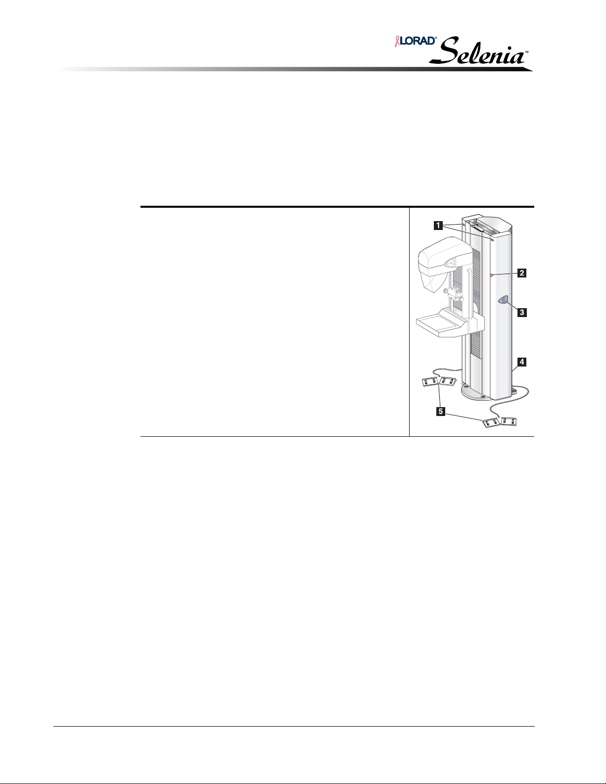
Installation and Hardware Maintenance Manual
Chapter 5—Startup, Shutdown, and Functional Tests
Controls and Displays
5.3.2 Using the SMPTE pattern for Brightness and Contrast Adjustments (Totoku Only)
1. From the AWS, select Admin>Test Patterns. Select SMPTE in the Pattern field.
2. Click Preview to display the full screen.
3. Adjust the Brightness and Contrast using the display submenus.
5.4 Gantry Controls and Displays
Gantry Controls
1. C-arm Rotation Angle displays on either side of the
Gantry show the C-arm angle.
2. Emergency Off Switches, located on each side of the
Gantry, immediately remove power from the Tubestand.
3. Gantry C-arm Rotation Switches, if equipped, are
located on each side of the Gantry, initiate C-arm
movement to a pre-programmed position.
4. The Input Power Circuit Breaker at the rear of the Gantry
provides overload protection.
5. Dual-Function Footswitches activate C-arm and
Compression Device movement.
5-8 MAN-00745
Page 85
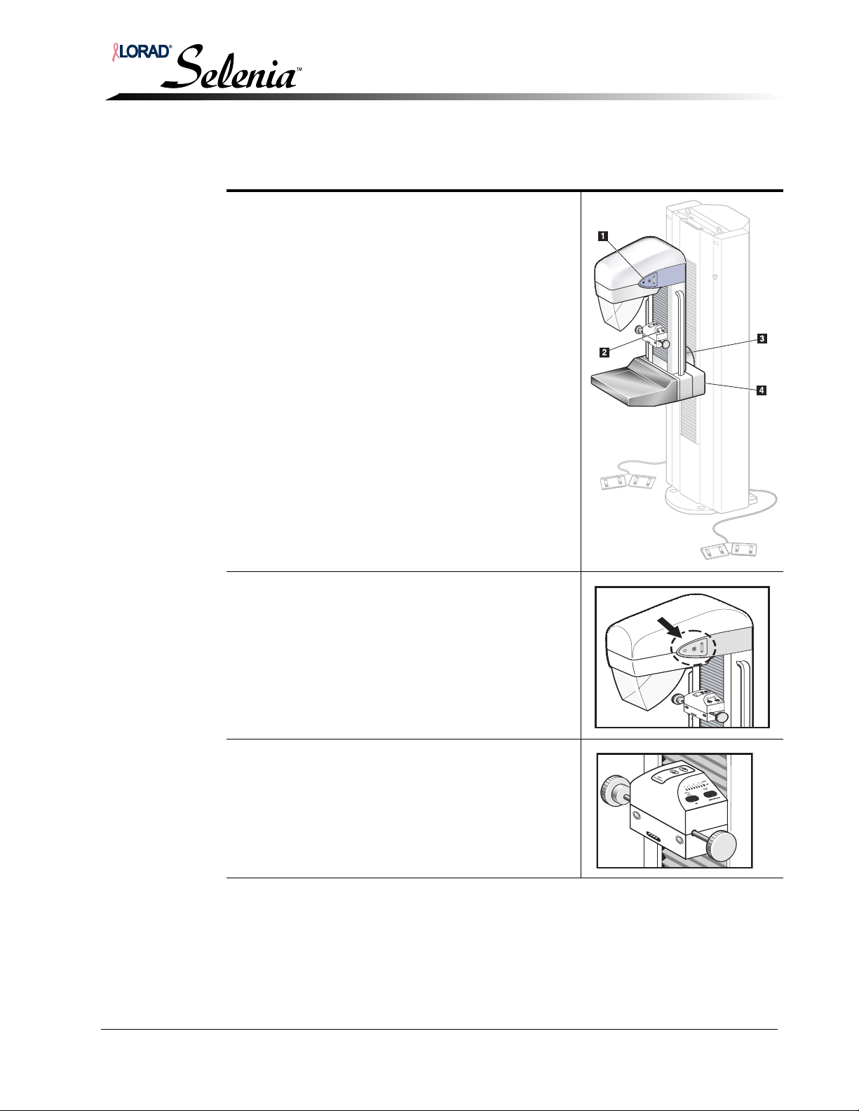
Installation and Hardware Maintenance Manual
Chapter 5—Startup, Shutdown, and Functional Tests
5.5 C-arm Controls and Displays
C-arm controls are located at the Tubehead, the
Compression Device, the C-arm Side Rails, and the rear
of the Image Receptor Support Device.
1. Tubehead Controls
2. Compression Device
3. Rear of the C-arm Side Rails
4. Rear of the Image Receptor
Controls and Displays
Tubehead Controls, located on either side of the x-ray
tube side covers, provide Collimator Override, C-arm
Rotation, and Light Field functions.
The Compression Device houses AEC Sensor control
and position LEDs, and displays compressed breast
thickness and force. Handwheels allow manual
compression control for patient positioning and
applying final compression force.
MAN-00745 5-9
Page 86
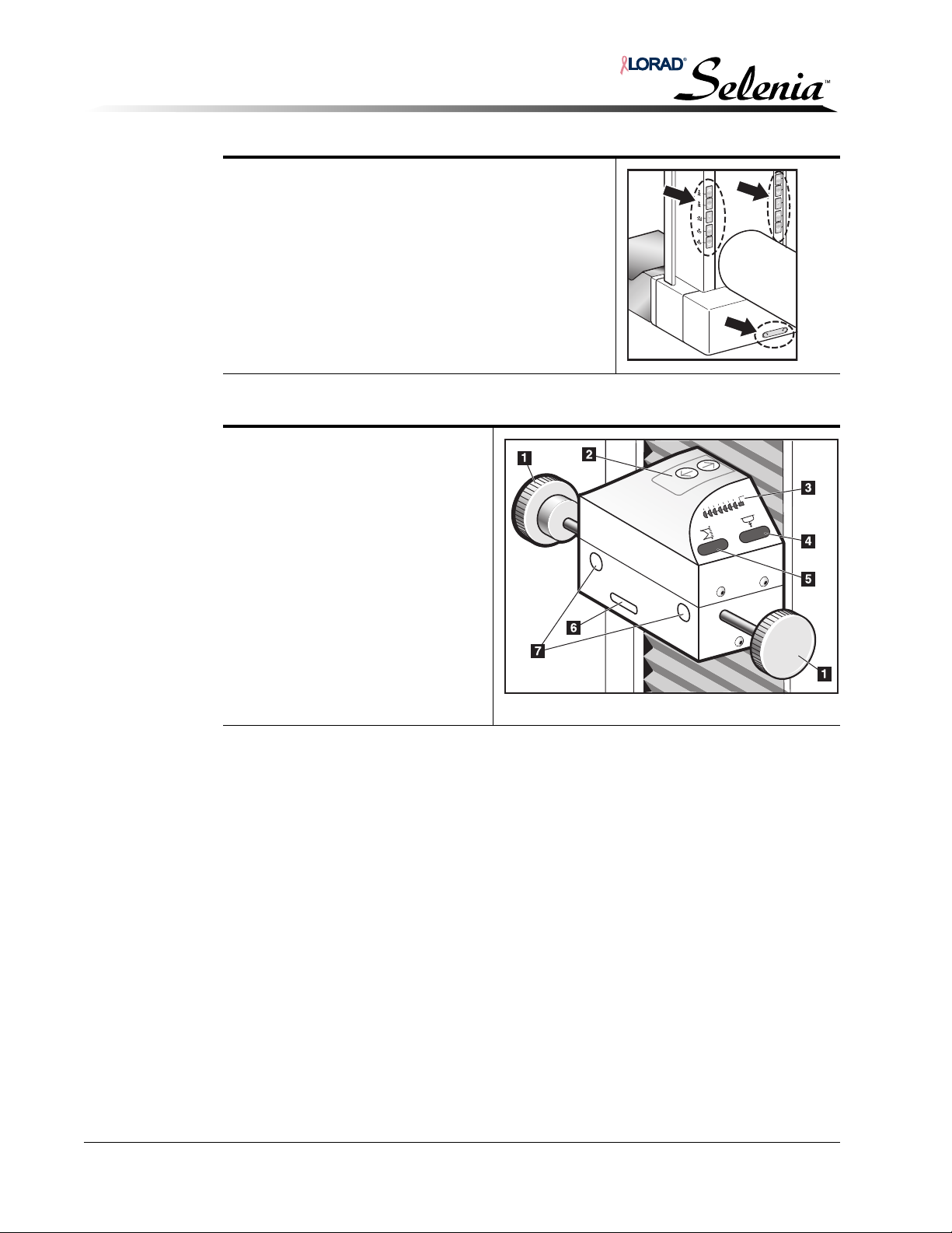
Installation and Hardware Maintenance Manual
Chapter 5—Startup, Shutdown, and Functional Tests
Controls and Displays
The rear edges of the C-arm Side Rail house recessed
push-button controls for motorized compression and
C-arm movement. An additional C-arm Rotation button
is available on the rear of the Image Receptor.
5.5.1 Compression Device Controls and Displays
Legend for Figure 5-9
1. Compression Handwheels.
2. AEC Sensor Position controls.
3. AEC Sensor Position Display.
4. Compression Force Display shows
the compression force through the
range of 10 lb to 67.4 lb (44.5 N to
300 N) in 1 lb (4.4 N) increments.
5. Compression Thickness Display
shows the thickness between 0 and
15 cm above the image receptor in
0.1 cm increments.
6. Compression Paddle Sensor
Receptacle.
7. Compression Paddle Docking
Sleeves.
POSITION
AEC
7
Figure 5-9: Compression Device
O
T
U
A
1
C
3
E
A
5
NEWTONS/LBS
CM
5-10 MAN-00745
Page 87
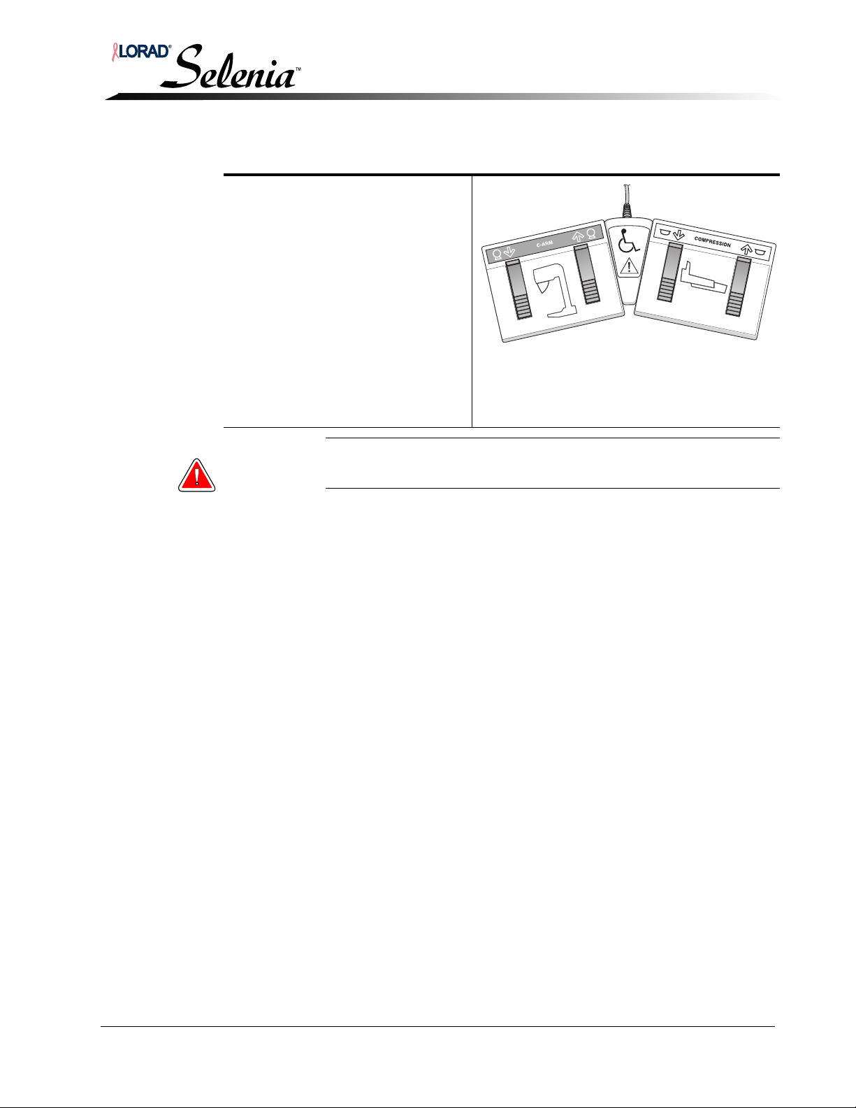
Installation and Hardware Maintenance Manual
Chapter 5—Startup, Shutdown, and Functional Tests
5.6 Dual Function Footswitches
The system has two footswitches, one
for C-arm and one for Compression
Up/Down movement. Locate the
footswitches for easy access at either
side of the C-arm.
Using the Footswitch:
1. Press the footswitch to activate.
2. Release the switch to stop
motorized movement.
Legend for Figure 5-10
1. C-arm Down
2. C-arm Up
3. Compression Down
4. Compression Up
Controls and Displays
Figure 5-10: The Dual Function Footswitch
Warning: Always position the footswitches so as to eliminate accidental
activation by patient, operators, or wheelchairs.
MAN-00745 5-11
Page 88
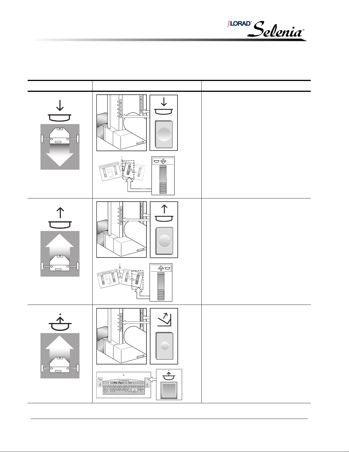
Installation and Hardware Maintenance Manual
C
-A
R
M
C
-A
R
M
COMPRESSION
COM
Chapter 5—Startup, Shutdown, and Functional Tests
Selenia Controls and Functional Tests
6.0 Selenia Controls and Functional Tests
Test the C-arm, Tubehead, and Footswitch functions to ensure mechanical integrity.
Function Control Location and Appearance Description/Functional Test
Compression Down Pressing a Compression Down button:
• Engages the compression brake.
• Turns on the light field lamp.
• Lowers the compression device.
Note… Once activated, the compression
brake remains engaged until compression
release is pressed.
Compression down movement stops:
• Upon release of the button.
• At the compression down force limit.
• At the lower compression travel limit.
Confirm the buttons function correctly.
Compression Up Pressing a Compression Up button:
• Raises the compression device.
• Does not release or activate the
compression brake.
Motorized compression up movement
automatically stops:
• Upon release of the button.
• Upon reaching the upper
compression travel limit.
Confirm the buttons function correctly.
Compression Release Pressing the Compression Release button:
• Releases the compression motor
brake.
• Raises the compression device
approximately 10 cm.
Confirm the buttons function correctly.
Note... The system disables all
compression release functions when a
localization paddle is installed (including
automatic compression release, if
enabled). Patient release is available
through the compression up functions.
5-12 MAN-00745
Page 89
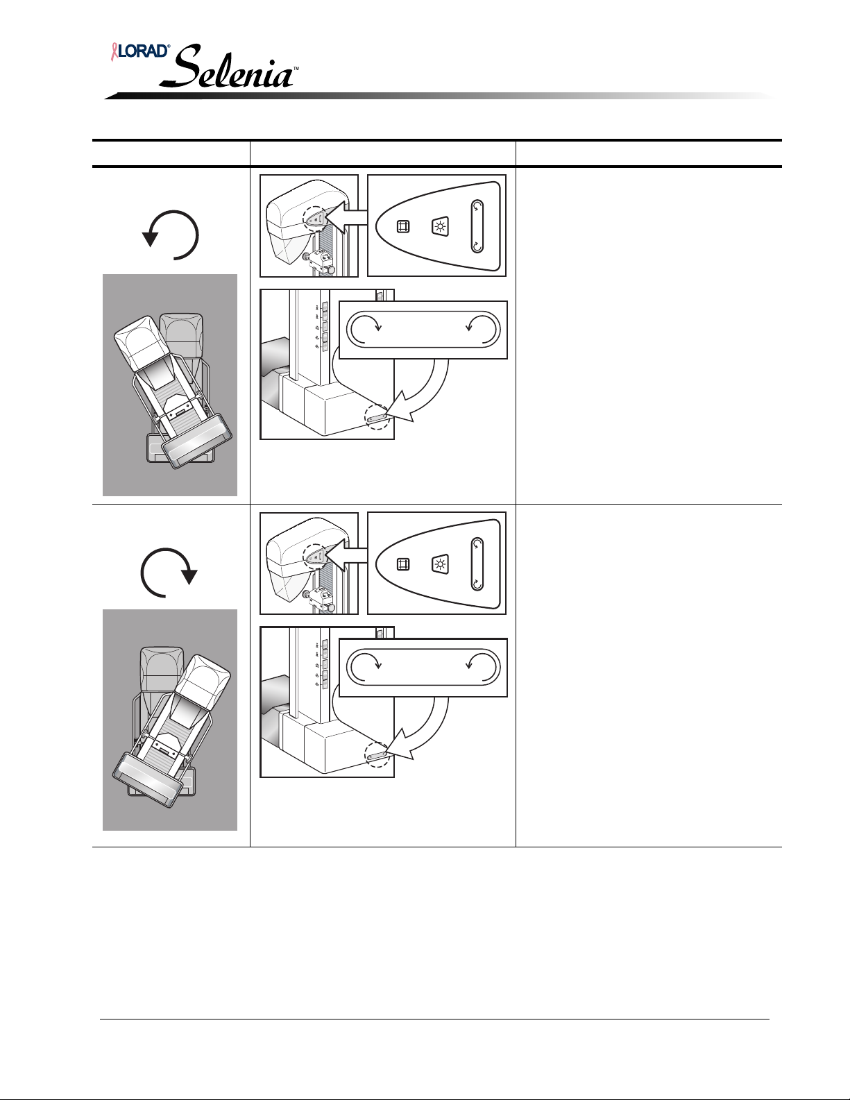
Installation and Hardware Maintenance Manual
Chapter 5—Startup, Shutdown, and Functional Tests
Selenia Controls and Functional Tests
Function Control Location and Appearance Description/Functional Test
Counterclockwise
C-arm Rotation
Clockwise C-arm
Rotation
When you press a C-arm Rotation switch,
rotation commences immediately and
ceases when you release the switch.
Operation:
Pressing this button initializes motorized
counterclockwise C-arm rotation.
C-arm movement is disabled when
compression force of 58 N (13 lb) or
greater is applied.
Confirm the C-arm Angle Rotation
Displays on the Gantry reflect the
changes in rotation.
Rotating the C-arm counterclockwise
changes the display to a more negative
reading.
Pressing this button initializes motorized
clockwise C-arm rotation.
C-arm movement is disabled when
compression force of 58 N (13 lb) or
greater is applied.
Confirm the C-arm Angle Rotation
Displays on the Gantry reflect the
changes in rotation.
Rotating the C-arm clockwise changes the
display to a more positive reading.
After making an oblique exposure, the Carm angle is stored in memory. When you
rotate the C-arm past 0 degrees for the
next exposure, the system automatically
stops the C-arm at the opposite oblique
angle.
MAN-00745 5-13
Page 90
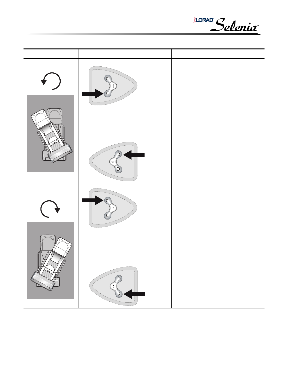
Installation and Hardware Maintenance Manual
Left
Side
Right
Side
Left
Side
Right
Side
Chapter 5—Startup, Shutdown, and Functional Tests
Selenia Controls and Functional Tests
Function Control Location and Appearance Description/Functional Test
Counterclockwise
C-arm Rotation
Clockwise C-arm
Rotation
Gantry C-arm Rotation Switches When you press a Gantry C-arm Rotation
switch, rotation commences after a short
delay and stops after a pre-programmed
amount of travel.
Operation:
• Service configures the rotation detent
position for the switches from 10-100
degrees of rotation; the default is 45
degrees.
• Press and hold a counterclockwise
Gantry C-arm Rotation switch;
audible beeps indicate the C-arm is
about to move, then movement starts.
• Movement stops when the preprogrammed rotation angle is
reached.
Press the center button and confirm the
C-arm moves to the zero degree (center)
position.
• Press and hold a clockwise Gantry
C-arm Rotation switch; audible beeps
indicate the C-arm is about to move,
then movement starts.
• Movement stops when the preprogrammed rotation angle is
reached.
Press the center button and confirm the
C-arm moves to the zero degree (center)
position.
5-14 MAN-00745
Page 91
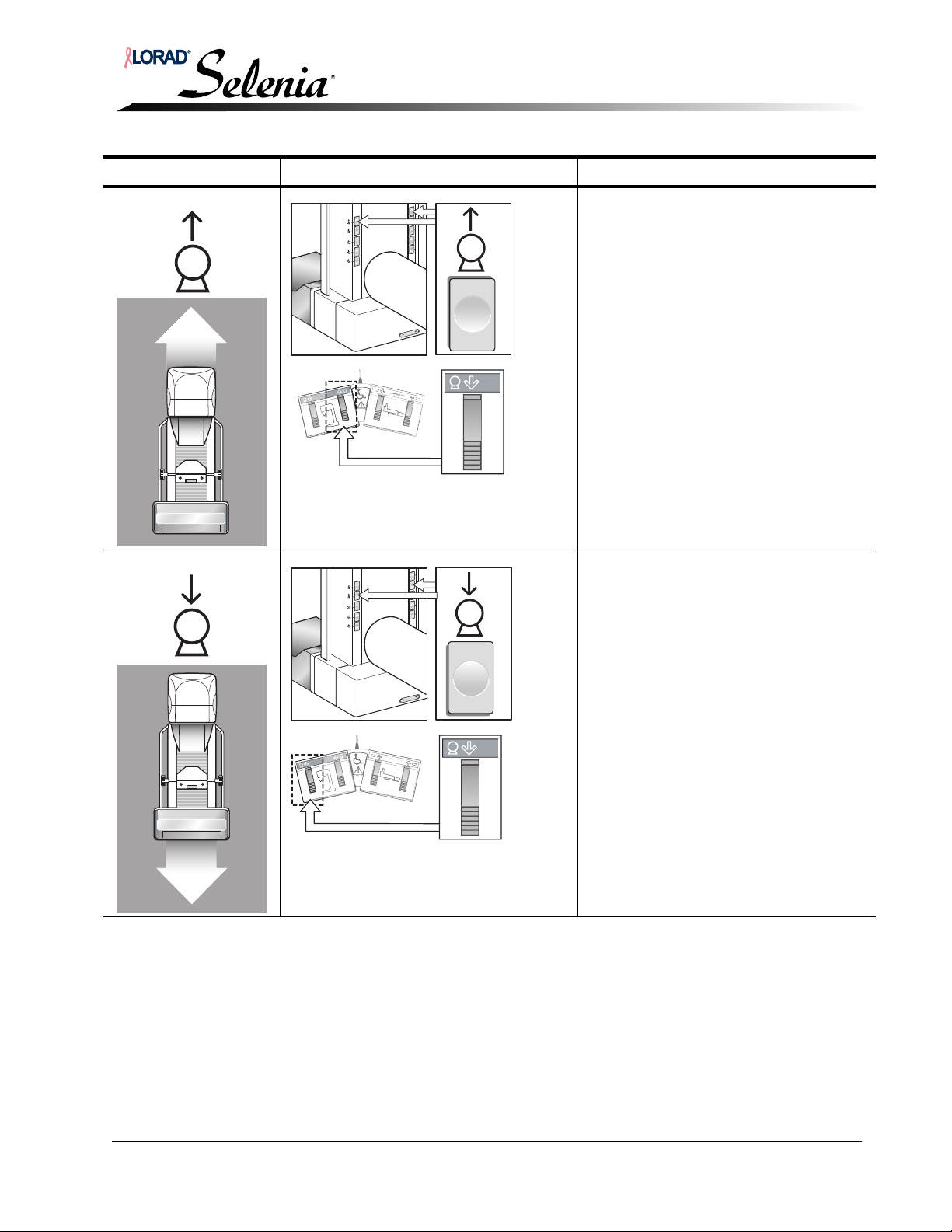
Installation and Hardware Maintenance Manual
C
-A
R
M
C
-A
R
C
OMPRESSION
C
-AR
M
C
OMPRESSION
M
Chapter 5—Startup, Shutdown, and Functional Tests
Selenia Controls and Functional Tests
Function Control Location and Appearance Description/Functional Test
C-arm Up Pressing this button moves the C-Arm up.
Motorized C-arm movement
automatically stops upon release of the
button or upon reaching the upper C-arm
travel limit.
C-arm movement is disabled when
compression force of 58 N (13 lb) or
greater is applied.
Confirm the buttons function correctly.
C-arm Down Pressing this button moves the C-Arm
down. Motorized C-arm movement
automatically stops upon release of the
button or upon reaching the lower C-arm
travel limit.
C-arm movement is disabled when
compression force of 58 N (13 lb) or
greater is applied.
Confirm the buttons function correctly.
MAN-00745 5-15
Page 92
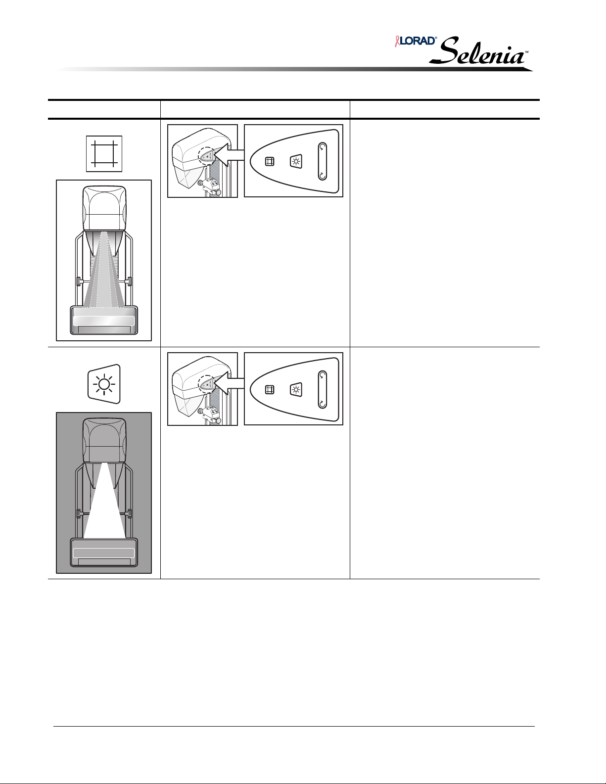
Installation and Hardware Maintenance Manual
Chapter 5—Startup, Shutdown, and Functional Tests
Selenia Controls and Functional Tests
Function Control Location and Appearance Description/Functional Test
Collimator Override The Collimator Override button allows
the collimator to cycle through the
available calibrated x-ray fields.
Choice of the collimator mode,
Automatic or Manual, is made in
Edit>Standard Setup.
Confirm the buttons function correctly
(press the light field lamp button to
visualize the x-ray field, and then press
the Collimator Override button).
The collimator device moves to another
field size and the light field size changes.
Light Field Lamp Pressing the light field lamp button turns
on the light field lamp for approximately
30 seconds, permitting you to visualize
the x-ray field.
The light field lamp automatically turns
on whenever a Compression Down
button is activated.
Confirm the buttons function correctly.
5-16 MAN-00745
Page 93
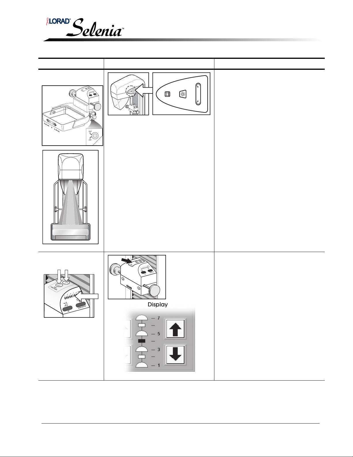
Installation and Hardware Maintenance Manual
Chapter 5—Startup, Shutdown, and Functional Tests
Selenia Controls and Functional Tests
Function Control Location and Appearance Description/Functional Test
Smart Paddle
System
AEC
Position
Smart Paddles incorporate a mechanical
function that permits the paddle to shift
~2.5 cm into a left, center, or right
position. While compression is applied,
the paddle cannot be unlocked. The
collimator is programmed to follow the
position of the Smart Paddles.
To test this functionality:
1. Install any Smart Paddle into the
compression device.
2. Shift the paddle into one of the detent
positions.
To change the position of a Smart Paddle:
1. Rotate and hold the knob on the side
of the paddle.
2. Move the paddle into the correct
position.
3. Release the knob to lock the paddle
in place.
4. Turn on the light field lamp. Confirm
that the collimator position matches
the paddle position.
5. Repeat this procedure for the other
two paddle positions.
Change the AEC Position by pressing one
of the arrows on the top of the
compression device.
(You can also change it at the AWS.)
To test this functionality:
1. Select an AEC mode using the AWS.
2. Change the AEC position using the
arrow buttons on the device and the
AWS display.
3. Confirm the position indicator on the
side of the device and on the AWS
display matches the current position.
4. Move the AEC position beyond #7 or
#1. Confirm the Auto position
indicator on the compression device
is illuminated and the AWS display
indicates Auto.
MAN-00745 5-17
Page 94
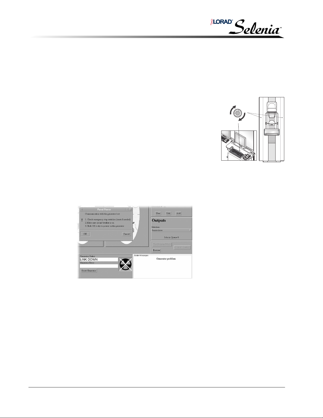
Installation and Hardware Maintenance Manual
Chapter 5—Startup, Shutdown, and Functional Tests
Continue with System Installation
7.0 Continue with System Installation
Continue with system installation using the Selenia Calibration and Software Maintenance
Manual.
8.0 Emergency Off Switches
There are three Emergency Off Switches on the Selenia, one on
either side of the Gantry and one on the AWS. Do not use the
Emergency Off Switches for routinely removing power from
the Selenia. They only affect the Gantry and should be used
only in an emergency.
To use, press any Emergency Off switch. The power to the
Gantry is immediately removed.
To restart the system after activating the switch:
1. Turn the Emergency Off switch one-quarter turn to reset it.
2. Wait for the Power Panel dialog box to appear. It indicates
the Communication with the Gantry is lost, and instructs you to inspect the Emergency
Switches and the circuit breaker.
3. If the Emergency Switches and the circuit breaker are set correctly, click OK to restart the
Gantry.
Figure 5-11: Power Panel Dialog Box
If the dialog box reappears:
Review the status of the Gantry before responding to the Power Panel Dialog Box.
• If the Gantry displays are On, click Cancel.
• If they are Off, click OK.
If the dialog box continues to reappear, shut down the AWS following the Shutdown
procedure—Refer to Section 9.0, p. 5-19. After waiting a minimum of four minutes, press the
On button to restart the unit.
5-18 MAN-00745
Page 95
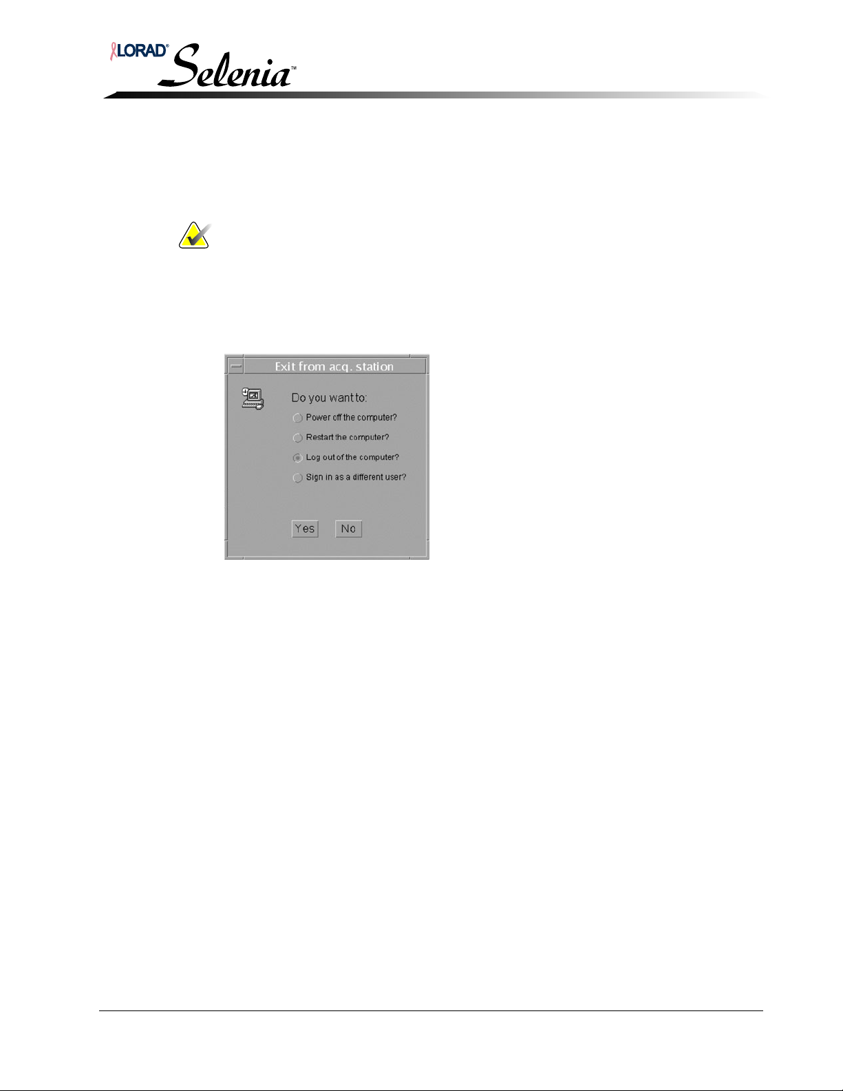
9.0 Shutdown Procedures
To properly shut down the Selenia System:
1. Exit any open patient procedure.
Note… Always shut down using the Exit menu as described below. Do not use the
task launcher or the bottom Solaris bar, except in emergencies.
2. Sign out of the application by clicking on File> Exit on the main menu.
aClick File and click Exit.
b Click the Power off the computer button on the dialog box.
cClick Yes.
Installation and Hardware Maintenance Manual
Chapter 5—Startup, Shutdown, and Functional Tests
Shutdown Procedures
Figure 5-12: Exit from AWS
3. At the Confirmation message, “Are you sure you would like to power off the computer?”
Click Yes.
4. When the Green Power indicator on the AWS turns off, the system is completely shut
down.
5. If the program does not close correctly, these steps shut the system down manually:
a After the application closes, click OK at the Logout Confirmation dialog box. If you
do not see the Logout confirmation box, click Exit on the Taskbar.
b At the Solaris Welcome window, type shutdown (all lower case) for the user
name and click OK or press Return.
c For the Password, type shutdown (all lower case) and click OK or press Return.
d When the Green Power indicator on the AWS turns off, the system is completely
shut down.
9.1 User Reboot and User Shutdown
There are two special users on the system: User Reboot and User Shutdown. These are
initiated from a command line or the Sun interface, not from the Selenia interface. Initiating
a User Reboot reboots the operating system. Initiating a User Shutdown provides for an
orderly shutdown of the system.
MAN-00745 5-19
Page 96

Installation and Hardware Maintenance Manual
Chapter 5—Startup, Shutdown, and Functional Tests
Shutdown Procedures
5-20 MAN-00745
Page 97

Installation and Hardware Maintenance Manual
Chapter 6—AWS Maintenance
1.0 Introduction
This chapter provides maintenance information and instructions for the AWS, including:
• Component identification
• Removing covers and panels
• Preventive maintenance procedures
• Component replacement procedures
Chapter 6—AWS Maintenance
Introduction
MAN-00745 6-1
Page 98
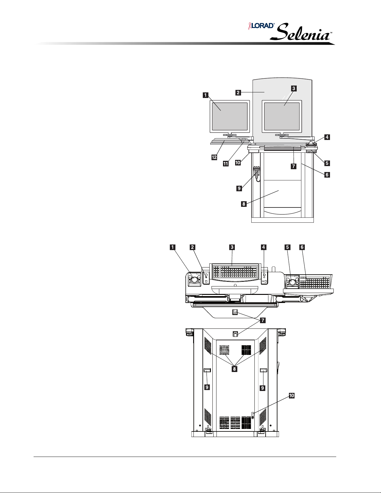
Installation and Hardware Maintenance Manual
Legend for Figure 6-1
1. TechMate Display
2. Radiation Shield
3. Selenia Display
4. Selenia Trackball
5. CD-RW Drive
6. Cooling Fan
7. Selenia Keyboard
8. TechMate Computer and UPS
(not shown, located behind cover)
9. Barcode reader
10. Storage Shelf
11. TechMate Trackball
12. TechMate Keyboard
Legend for Figure 6-2
1. Selenia Trackball
2. Right LED Board (x-ray LED board)
3. Selenia Keyboard
4. Left LED Board (x-ray LED board)
5. TechMate Trackball
6. TechMate Keyboard
7. Circuit Breaker
8. Cooling Fans (4)
9. Rear Cover Handles
10. Selenia UPS Reset
Chapter 6—AWS Maintenance
Introduction
1.1 Component Identification
AWS Components—Front View
Figure 6-1: AWS Components—Front View
Figure 6-2: AWS Components—Top/Rear View
6-2 MAN-00745
Page 99
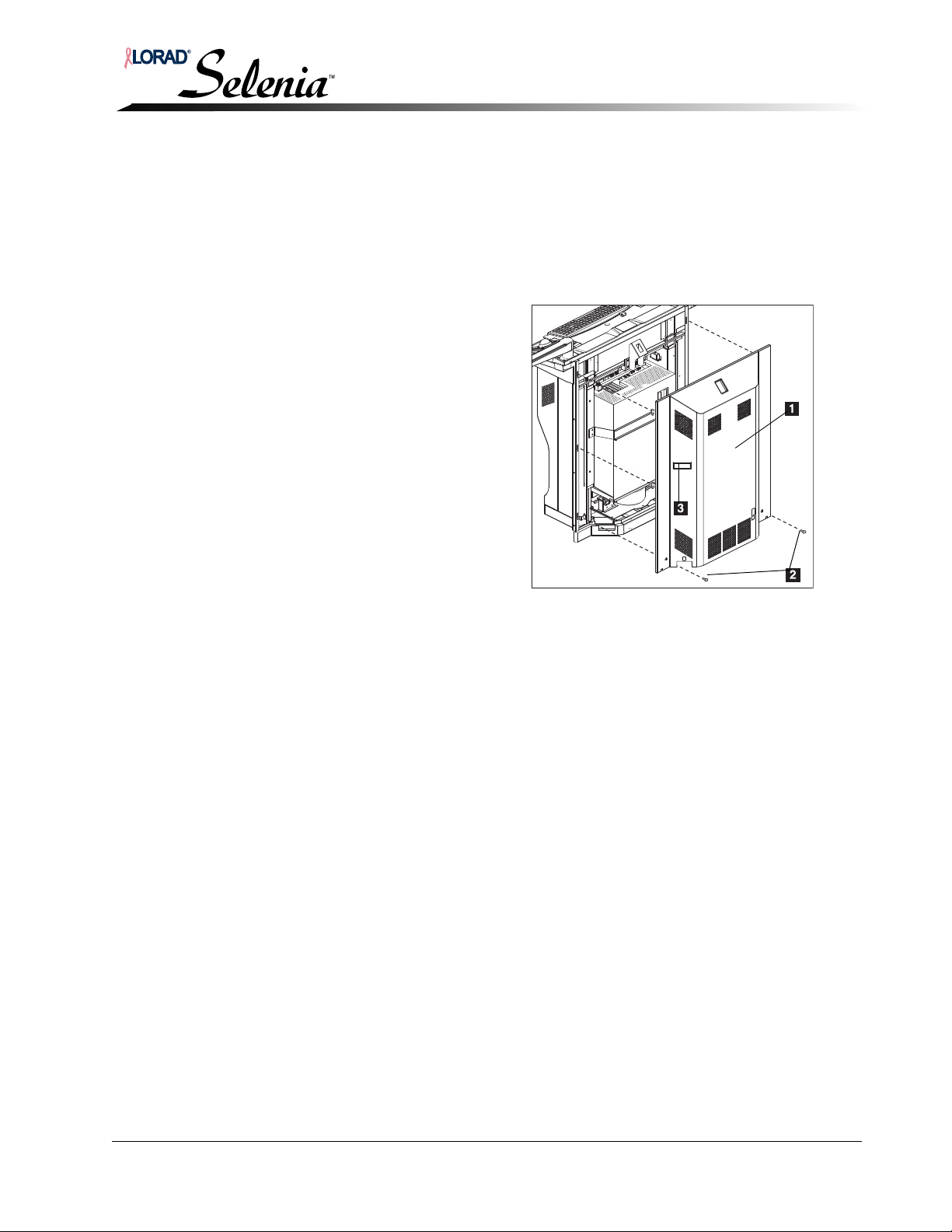
Installation and Hardware Maintenance Manual
Chapter 6—AWS Maintenance
Accessing Internal Components—Selenia AWS
2.0 Accessing Internal Components—Selenia AWS
2.1 Rear Cover Removal
1. Shut the system down.
2. Remove the two rear cover screws; see Figure 6-3.
3. Grasp the handles on each side of the cover.
4. Slide the cover upwards, then pull backwards to remove the cover.
5. Disconnect the cooling fan harness.
Legend for Figure 6-3
1. Rear Cover
2. Rear Cover Mounting Screws (two)
3. Rear Cover Handles
(two, only one shown)
Figure 6-3: AWS Covers Removal
MAN-00745 6-3
Page 100
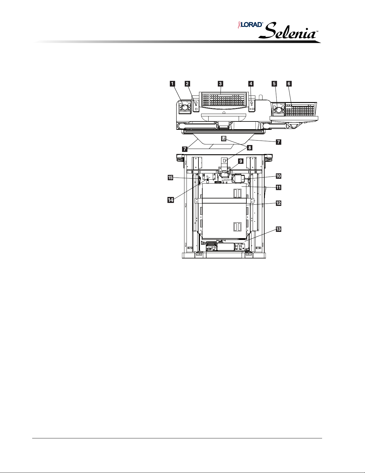
Installation and Hardware Maintenance Manual
Legend for Figure 6-4
1. Selenia Trackball
2. Right LED Board (x-ray LED board)
3. Selenia Keyboard
4. Left LED Board (x-ray LED board)
5. TechMate Trackball
6. TechMate Keyboard
7. AWS Cooling Fans
8. Circuit Breaker
9. Barcode Reader Power Supply
10. Display Power Supply
11. Computer
12. Uninterruptible Power Supply
(behind computer)
13. Power Distribution Assembly (PDA)
14. Low Voltage Power Supply
15. Power Control Board
Chapter 6—AWS Maintenance
Accessing Internal Components—Selenia AWS
2.2 Internal Components
To access internal components or wiring inside the AWS; see Figure 6-4.
Figure 6-4: Internal Components
6-4 MAN-00745
 Loading...