

Page 1

Osteoporosis Assessment
SERVICE
8/14/03
Artwork and Signature File for:
9-500-0255 MANUAL, AFFINITY SERVICE
Artwork consists of:
• Two hundred and twelve (212) 8 ½ inch x 11 inch pages.
REV AUTHORED BY DATE
A. TAMBASCIO 7/24/2003
REV DRAFTED BY DATE
BILL MOSES 8/5/2003
PROPRIETARY: This document contains
proprietary data of Hologic, Inc. No
disclosure, reproduction or use of any
part thereof may be made except by
written permission from Hologic.
REV. RELEASE DATE:
LORAD© Breast Cancer Detection
DirectRay© Digital Imaging
FLUOROSCAN
TITLE DOCUMENT NUMBER REV
©
C-arm Imaging
MANUAL, AFFINITY
ARTWORK SIZE A SHEET 1 OF 1
AW-00227 005
Form ENG-0034-T03, Rev. 001
Page 2

Page 3
Page 4

Page 5

Service Manual
for Affinity Series Mammography Systems
Part Number 9-500-0255
Revision 005
Page 6

Page 7

Service Manual
Table of Contents
List of Figures ..................................................................................................... -vii
List of Tables ....................................................................................................... -ix
Preface ..............................................................................................................P-xi
1.0 Using the Service Manual ..................................................................................................... P-xi
1.1 Warnings, Cautions and Notes ...................................................................................... P-xii
2.0 Acronym List ........................................................................................................................ P-xii
Chapter 1: General Information .........................................................................1-1
1.0 Introduction ........................................................................................................................... 1-1
1.1 Intended Uses .................................................................................................................. 1-1
1.2 Required Tools and Equipment ........................................................................................ 1-2
2.0 Safety ..................................................................................................................................... 1-2
2.1 Electrical Safety ............................................................................................................... 1-2
2.2 Interlocks ......................................................................................................................... 1-3
2.3 Mechanical Safety ........................................................................................................... 1-3
2.4 Radiation Safety ............................................................................................................... 1-4
3.0 Unit Description .................................................................................................................... 1-5
3.1 Gantry and C-Arm ...........................................................................................................1-5
3.2 Control Panel .................................................................................................................. 1-7
4.0 Compliance Data ................................................................................................................... 1-8
4.1 Compliance Statement ..................................................................................................... 1-8
4.1.1 Remote Indication of the Ready State ........................................................................ 1-8
4.2 Certifiable Components ................................................................................................... 1-9
4.3 Location of Labels .........................................................................................................1-10
P/N 9-500-0255 i
Page 8

Service Manual
Chapter 2: System Installation ........................................................................... 2-1
1.0 Room Planning .......................................................................................................................2-1
2.0 Unpacking Instructions ...........................................................................................................2-2
2.1 Receiving Instructions ......................................................................................................2-2
2.2 Un-Crating the Unit .........................................................................................................2-2
3.0 Unit Installation ......................................................................................................................2-4
3.1 Input Power Configuration ...............................................................................................2-4
3.2 Power Cable Connection .................................................................................................2-5
3.3 Remote X-ray ON/Power ON Light Connection ...............................................................2-6
3.4 Control Panel Installation .................................................................................................2-6
3.4.1 Control Panel to Gantry Installation ..........................................................................2-6
3.4.2 Control Panel Remote Location Installation ...............................................................2-7
3.5 Securing Unit in Position ..................................................................................................2-8
3.6 Installing the Unit Accessories ..........................................................................................2-8
3.6.1 Exposure Footswitch .................................................................................................2-8
3.6.2 Dual Function Footswitch(es) ....................................................................................2-9
3.6.3 Connecting Film Labeling Devices ..........................................................................2-10
3.7 Initial Start Up Procedures ..............................................................................................2-10
3.7.1 Remote X-ray ON Light Configuration .....................................................................2-10
3.7.2 Initial Power Up ......................................................................................................2-11
3.7.3 Setting Operational Parameters ...............................................................................2-11
3.8 Final Operational Setup .................................................................................................2-11
3.8.1 Installing the Radiation Shield .................................................................................2-12
Chapter 3: Functional Checks/Setting Defaults ................................................. 3-1
1.0 Controls and Indicators ...........................................................................................................3-1
2.0 System Power Up ...................................................................................................................3-2
2.1 Pre-Power Up Checks ......................................................................................................3-2
2.2 Power Up Sequence .........................................................................................................3-2
2.3 Post Power-Up Checks .....................................................................................................3-3
3.0 The Affinity Series Control Panel ............................................................................................3-8
3.1 Control Panel Screens ......................................................................................................3-9
4.0 Setting User Defaults ............................................................................................................3-13
5.0 Setting Exposure Technique Defaults ....................................................................................3-13
ii P/N 9-500-0255
Page 9

Service Manual
Chapter 4: Calibrations and Performance Checks ..............................................4-1
1.0 Introduction ........................................................................................................................... 4-1
2.0 Calibration Procedures ........................................................................................................... 4-1
2.1 Entering Calibration Mode ............................................................................................... 4-2
3.0 Compression System Calibration Procedures .......................................................................... 4-7
3.1 Compression Force Calibration ........................................................................................ 4-7
3.2 Compression Thickness Calibration ................................................................................. 4-8
4.0 Exposure System Calibration .................................................................................................. 4-9
4.1 Tube Voltage Calibration ................................................................................................. 4-9
4.2 Check mA Calibration ................................................................................................... 4-11
4.3 Filament Current (mA) Calibration ................................................................................. 4-11
4.4 Backup Timer Test ......................................................................................................... 4-15
5.0 Automatic Exposure Control System Calibration .................................................................. 4-16
5.1 AEC Detector Gain Calibration ...................................................................................... 4-17
5.2 AEC Detect Board—R1 Adjustment ............................................................................... 4-18
5.3 Initial Calibration—Large Focal Spot (Mo) ..................................................................... 4-18
5.4 kV Tracking—Large Focal Spot (Mo) .............................................................................. 4-19
5.5 Initial Calibration—Large Focal Spot (Rh) ...................................................................... 4-20
5.6 kV Tracking—Large Focal Spot (Rh) ............................................................................... 4-21
5.7 Starting AEC Values—Large Focal Spot .......................................................................... 4-21
5.8 Performance Test—Large Focal Spot (Mo) ..................................................................... 4-21
5.9 Performance Test—Large Focal Spot (Rh) ...................................................................... 4-22
5.10 Initial Calibration—Small Focal Spot (Mo) ................................................................... 4-23
5.11 kV Tracking - Small Focal Spot (Mo) ............................................................................ 4-24
5.12 Initial Calibration—Small Focal Spot (Rh) .................................................................... 4-24
5.13 Starting AEC Values - Small Focal Spot ........................................................................ 4-25
5.14 Performance Test - Small Spot (Mo) ............................................................................. 4-25
5.15 Performance Test - Small Spot (Rh) .............................................................................. 4-26
5.16 HTC Factor (Offset) Calibration ................................................................................... 4-27
5.17 Large Bucky (24 x 30 cm) Factor Calibration ............................................................... 4-27
5.18 Compression Thickness Threshold Adjustment ............................................................ 4-28
5.19 C-arm Safety Function Check ...................................................................................... 4-31
6.0 Performance Checks ............................................................................................................ 4-32
6.1 Half-Value Layer ...........................................................................................................4-32
6.2 Reproducibility and Linearity in Manual Mode .............................................................. 4-35
6.3 Reproducibility in Auto-Time Mode .............................................................................. 4-36
6.4 Reproducibility in Auto-kV Mode .................................................................................. 4-36
6.5 Reproducibility in Auto-Filter Mode .............................................................................. 4-36
6.6 Bucky Device Performance Check ................................................................................. 4-40
6.7 AEC Limits Performance Check ..................................................................................... 4-40
6.8 System Level Functional Check ..................................................................................... 4-41
6.9 Optical Density (Users Preference) Verification ............................................................. 4-41
6.10 IRSD Leakage Check ................................................................................................... 4-41
6.11 X-ray Tubehead Leakage Check ................................................................................... 4-42
P/N 9-500-0255 iii
Page 10

Service Manual
7.0 X-ray and Light Field Check and Alignment Procedures ........................................................4-44
7.1 X-ray Beam Alignment Template ....................................................................................4-44
7.2 Exposing and Viewing the X-ray Field ............................................................................4-45
7.3 Aperture Adjustment Procedures ....................................................................................4-46
7.4 Auto Aperture Alignment ...............................................................................................4-47
7.4.1 Align the 24 x 30 cm Large Focal Spot ....................................................................4-47
7.4.2 Align the 18 x 24 cm Large Focal Spot ....................................................................4-48
7.5 Magnification Full Field (18 x 24 cm) Aperture Alignment (SM FS) .................................4-50
7.6 10 cm Coned-down Contact Aperture Alignment (LG FS) ...............................................4-50
7.7 7.5 cm Spot Contact Aperture Alignment (LG FS) ...........................................................4-51
7.8 7.5 cm Spot Magnification Aperture Alignment (SM FS) .................................................4-51
7.9 X-ray Field Alignment Verification .................................................................................4-51
7.10 Light Field Alignment Check and Adjustment ...............................................................4-51
7.11 Light Field Edge Contrast Check ...................................................................................4-53
7.12 Light Field Illuminance Check ......................................................................................4-55
8.0 Mechanical Adjustments ......................................................................................................4-56
8.1 Compression Chain Tension Adjustment ........................................................................4-56
8.2 Compression Display Potentiometer Adjustment ............................................................4-57
8.3 Compression Force Load Cell Setting .............................................................................4-57
8.4 C-arm Safety Microprocessor Board Calibration/Vertical Drive Force Load Cell Setting ..4-58
9.0 Maintenance Procedures ......................................................................................................4-59
9.1 kV Control Offset Calibration .........................................................................................4-59
Chapter 5: Maintenance—General .................................................................... 5-1
1.0 Introduction ............................................................................................................................5-1
2.0 Preventive Maintenance .........................................................................................................5-1
3.0 Troubleshooting .....................................................................................................................5-2
3.1 Theory of Operation Overview ........................................................................................5-2
3.1.1 Operator Control Panel .............................................................................................5-2
3.1.2 Power Distribution ....................................................................................................5-3
3.1.3 System Control ..........................................................................................................5-3
3.1.4 Tubehead Functions ..................................................................................................5-4
3.1.5 X-ray Tube Control ....................................................................................................5-4
3.1.6 Mechanical Functions ...............................................................................................5-5
3.1.7 Exposure Control .......................................................................................................5-6
3.1.8 Automatic Exposure Control ......................................................................................5-7
3.2 Alert Codes Log ................................................................................................................5-8
3.3 System Data Retrieval ....................................................................................................5-10
3.3.1 Downloading Alert Codes Log ................................................................................5-11
3.3.2 Downloading Calibration Data ...............................................................................5-11
3.3.3 Uploading Calibration Data ....................................................................................5-12
iv P/N 9-500-0255
Page 11

Service Manual
Chapter 6: Maintenance—Remove and Replace Procedures ............................. 6-1
1.0 Introduction ............................................................................................................................6-1
2.0 Gantry Components—Remove and Replace ...........................................................................6-1
2.1 Removing Covers and Panels From the Gantry .................................................................6-3
2.1.1 Left and Right Side Panels .........................................................................................6-4
2.1.2 Upper Rear Gantry Panel ..........................................................................................6-4
2.1.3 Rear Connector Panel ...............................................................................................6-5
2.1.4 Lower Rear Panel/Power Distribution Assembly ........................................................6-5
2.2 Gantry Cover Components ...............................................................................................6-6
2.2.1 C-arm Angle Display Boards .....................................................................................6-6
2.2.2 Emergency Off Switches ............................................................................................6-7
2.3 Control Panel Components ..............................................................................................6-8
2.3.1 Display Microprocessor Board ..................................................................................6-9
2.3.2 LCD Display .............................................................................................................6-9
2.4 Left-Side Gantry Components .........................................................................................6-10
2.4.1 High Voltage Generator Assembly ..........................................................................6-10
2.4.2 Power Control Board ...............................................................................................6-16
2.4.3 Auxiliary Power Distribution Board .........................................................................6-16
2.5 Right-Side Gantry Components ......................................................................................6-17
2.5.1 Host Microprocessor Board .....................................................................................6-17
2.5.2 Firmware Replacement ...........................................................................................6-18
2.5.3 Communications Interface Board ............................................................................6-18
2.5.4 Low Voltage Power Supply .....................................................................................6-19
2.5.5 C-arm Safety Microprocessor Board ........................................................................6-19
2.6 Internal Gantry Components ..........................................................................................6-20
2.6.1 Main Circuit Breaker ...............................................................................................6-20
2.6.2 The C-arm Angle Detent Microswitch .....................................................................6-21
2.6.3 The C-arm Rotation Potentiometer ..........................................................................6-22
2.6.4 The C-arm Vertical Drive Actuator ..........................................................................6-23
3.0 C-Arm Components—Remove and Replace .........................................................................6-26
3.1 C-Arm Frame Components .............................................................................................6-29
3.1.1 Patient Face Shield Installation and Removal ..........................................................6-29
3.1.2 C-arm Frame Covers ...............................................................................................6-30
3.1.3 Filament Protection Board .......................................................................................6-32
3.1.4 3-Position Switch Board ..........................................................................................6-33
3.1.5 7-Position Switch Board ..........................................................................................6-33
3.1.6 C-arm Switch Interface Board ..................................................................................6-34
3.1.7 C-arm Accessory Detect Board ................................................................................6-34
3.2 Tubehead Components ..................................................................................................6-35
3.2.1 Tubehead Covers ....................................................................................................6-35
3.2.2 X-ray Tube ..............................................................................................................6-36
3.2.3 Tubehead Control Board .........................................................................................6-38
3.2.4 C-Arm Cooling Fan .................................................................................................6-40
3.2.5 Beam Limiting Assembly .........................................................................................6-41
3.2.6 Aperture Detect Board ............................................................................................6-41
3.2.7 Filter Shifter Assembly .............................................................................................6-42
3.2.8 Light Field Lamp Assembly with Fan .......................................................................6-43
3.2.9 Light Field Lamp Assembly—Lamp Replacement ....................................................6-44
3.2.10 Light Field Lamp Assembly—Fan Replacement .....................................................6-44
3.2.11 Motorized Mirror Assembly ...................................................................................6-45
P/N 9-500-0255 v
Page 12

Service Manual
3.3 Compression Assembly .................................................................................................. 6-46
3.3.1 Compression Device Covers ................................................................................... 6-46
3.3.2 Compression Motor & Brake Assembly ................................................................... 6-46
3.3.3 Compression Clutch & Clutch Brake Assembly ....................................................... 6-48
3.3.4 Compression / AEC Position Display Boards ........................................................... 6-50
3.3.5 Compression Tray Sensor Board ............................................................................. 6-50
3.3.6 Compression Thickness Potentiometer .................................................................... 6-51
3.4 IRSD Components ......................................................................................................... 6-54
3.4.1 Image Receptor Support Device Covers .................................................................. 6-54
3.4.2 AEC Detector Assembly .......................................................................................... 6-55
3.4.3 AEC Position Detect Board ..................................................................................... 6-56
3.4.4 Accessory Detect Board .......................................................................................... 6-57
3.4.5 AEC Position Compression Display Microprocessor Board ...................................... 6-57
Chapter 7: Parts List ........................................................................................... 7-1
1.0 Instructions ............................................................................................................................ 7-1
1.1 The Replacement Parts Lists ............................................................................................. 7-1
Appendix A: Specifications ................................................................................A-1
1.0 System Specifications .............................................................................................................A-1
1.1 Electrical Input Specifications ..........................................................................................A-1
1.2 Unit Measurements .........................................................................................................A-1
1.3 Operating Environment ...................................................................................................A-2
1.4 Storage Environment ........................................................................................................A-2
1.5 C-arm Specifications ........................................................................................................A-3
1.6 Compression Specifications .............................................................................................A-3
1.7 Compression Paddles ......................................................................................................A-4
1.8 Apertures ......................................................................................................................... A-5
1.9 Magnification ..................................................................................................................A-5
1.10 Image Receptor Support Device ....................................................................................A-6
1.11 C-arm Functions ............................................................................................................A-6
1.12 X-ray Source, Filtration and Collimation ........................................................................A-6
1.13 High Voltage Generator Specification (in compliance with IEC 601-2-7) .......................A-8
1.14 Image Receptors ..........................................................................................................A-10
1.15 Automatic Exposure Control Specifications .................................................................. A-10
1.16 Modes of Operation .................................................................................................... A-11
2.0 Room Requirements .............................................................................................................A-12
Appendix B: Technical References .....................................................................B-1
1.0 Introduction ........................................................................................................................... B-1
2.0 Test Points ............................................................................................................................. B-1
3.0 LED Indicators ....................................................................................................................... B-6
4.0 Image Receptor Detect Board—Sensor Combinations ............................................................ B-8
5.0 Fuses ...................................................................................................................................... B-9
6.0 Jumpers ................................................................................................................................ B-11
vi P/N 9-500-0255
Page 13

Service Manual
List of Figures
Figure 1-1 The Affinity System .......................................................................................................1-1
Figure 1-2 Affinity Gantry and C-Arm ............................................................................................1-6
Figure 1-3 Affinity Series Control Panel .........................................................................................1-7
Figure 1-4 Compliance Label Locations.......................................................................................1-10
Figure 2-1 Example Room Layout ..................................................................................................2-1
Figure 2-2 Un-Crating the Gantry ..................................................................................................2-2
Figure 2-3 Isolation Transformer Taps............................................................................................2-5
Figure 2-4 User Lamp (X-ray ON/Power ON) Connections ............................................................2-6
Figure 2-5 Remote Control Panel Installation .................................................................................2-7
Figure 2-6 Rear Connector Panel (Shroud removed) and Lower Rear Panel Connections ...............2-8
Figure 2-7 Connecting a Footswitch ..............................................................................................2-9
Figure 2-8 Installing the Radiation Shield.....................................................................................2-12
Figure 3-1 Affinity Controls and Indicators.....................................................................................3-1
Figure 3-2 The C-arm Controls ......................................................................................................3-3
Figure 3-3 Dual Function Footswitch .............................................................................................3-5
Figure 3-4 Emergency OFF ............................................................................................................3-6
Figure 3-5 The Tubehead Controls.................................................................................................3-7
Figure 3-6 The Affinity Series Control Panel...................................................................................3-8
Figure 3-7 The Run Mode Screen ..................................................................................................3-9
Figure 3-8 The User Default Screen ...............................................................................................3-9
Figure 3-9 The Exposure Default Screen ......................................................................................3-10
Figure 3-10 The Calibration Mode/Debug Screen ........................................................................3-10
Figure 3-11 Calibration Screen #1—Calibration Mode ................................................................3-11
Figure 3-12 Calibration Screen #2—Calibration Mode ................................................................3-11
Figure 3-13 Calibration Screen #3—Calibration Mode ................................................................3-12
Figure 3-14 Calibration Screen #4—Calibration Mode ................................................................3-12
Figure 4-1 Compression Force Calibration Setup ...........................................................................4-7
Figure 4-2 Compression Thickness Calibration Setup.....................................................................4-8
Figure 4-3 High Voltage Generator Calibration Setup ..................................................................4-10
Figure 4-4 Example—Filament Waveforms Pattern ......................................................................4-12
Figure 4-5 Example—Backup Timer Time-out Signal ...................................................................4-16
Figure 4-6 Half-Value Layer Setup ...............................................................................................4-33
Figure 4-7 Reproducibility & Linearity Check Setup.....................................................................4-35
Figure 4-8 IRSD Shielding Check.................................................................................................4-42
Figure 4-9 Tubehead Shielding Check .........................................................................................4-43
Figure 4-10 X-ray Beam Alignment Template ..............................................................................4-44
Figure 4-11 Aperture Alignment ..................................................................................................4-46
Figure 4-12 Affinity Apertures......................................................................................................4-47
Figure 4-13 Auto Aperture Alignment—18 x 24 cm Large Focal Spot ..........................................4-49
Figure 4-14 Light Field Size Adjustment.......................................................................................4-53
Figure 4-15 Light Field Edge Contrast Check................................................................................4-54
Figure 4-16 Probe Locations—Light Field Illuminance.................................................................4-55
Figure 4-17 Adjustment—Light Field Illuminance ........................................................................4-55
Figure 4-18 Adjustment - Compression Motor Chain ...................................................................4-56
Figure 4-19 kV Offset Calibration—Calibration Screen #3 ...........................................................4-59
Figure 5-1 Connecting Laptop Computer to Affinity .....................................................................5-11
Figure 6-1 Gantry Components......................................................................................................6-2
List of Figures
P/N 9-500-0255 vii
Page 14

Service Manual
List of Figures
Figure 6-2 Gantry Components—Covers and Panels ..................................................................... 6-3
Figure 6-3 Rear Connector and Lower Rear Panels—Removal....................................................... 6-5
Figure 6-4 C-arm Angle Display Board—Removal......................................................................... 6-6
Figure 6-5 Emergency Off Switch—Removal................................................................................. 6-7
Figure 6-6 Control Panel Components .......................................................................................... 6-8
Figure 6-7 HV Generator Assembly (old style mounting plate)—Removal ................................... 6-12
Figure 6-8 HV Generator Assembly (new style mounting plate)—Removal.................................. 6-15
Figure 6-9 Microprocessor Firmware Chip—Replacement........................................................... 6-18
Figure 6-10 Main Circuit Breaker—Removal............................................................................... 6-20
Figure 6-11 C-arm Detent Microswitch—Removal ...................................................................... 6-21
Figure 6-12 C-arm Rotation Potentiometer—Removal ................................................................. 6-22
Figure 6-13 Shipping Collar Installation of VTA Rail ................................................................... 6-23
Figure 6-14 Components of the Vertical Drive Assembly............................................................. 6-24
Figure 6-15 C-arm Frame Components........................................................................................ 6-26
Figure 6-16 Tubehead / Beam Limiting Components ................................................................... 6-27
Figure 6-17 Compression Device Components ........................................................................... 6-28
Figure 6-18 IRSD Components.................................................................................................... 6-29
Figure 6-19 Patient Face Shield................................................................................................... 6-29
Figure 6-20 C-arm Frame Covers................................................................................................. 6-31
Figure 6-21 Filament Protection Board—Removal....................................................................... 6-32
Figure 6-22 C-arm Switch Pads—Removal .................................................................................. 6-33
Figure 6-23 C-Arm Accessory Detect Board—Removal............................................................... 6-34
Figure 6-24 Tubehead Covers—Removal .................................................................................... 6-35
Figure 6-25 X-ray Tube—Removal .............................................................................................. 6-36
Figure 6-26 Tubehead Control Board—Removal ......................................................................... 6-38
Figure 6-27 C-Arm Cooling Fan—Removal ................................................................................. 6-40
Figure 6-28 Aperture Detect Board—Removal ............................................................................ 6-41
Figure 6-29 Filter Shifter Assembly—Removal............................................................................. 6-42
Figure 6-30 Light Field Lamp Assembly with Fan—Removal ....................................................... 6-43
Figure 6-31 Motorized Mirror Assembly—Removal..................................................................... 6-45
Figure 6-32 Compression Motor & Brake Assembly—Removal ................................................... 6-47
Figure 6-33 Compression Clutch & Clutch Brake Assembly—Removal ....................................... 6-49
Figure 6-34 Compression / AEC Position Display Boards—Removal............................................ 6-50
Figure 6-35 Removal of Timing Belt from Upper Block Assembly ............................................... 6-52
Figure 6-36 Removal of Timing Belt from Bearing Block Assembly ............................................. 6-53
Figure 6-37 Compression Thickness Potentiometer—Removal .................................................... 6-53
Figure 6-38 IRSD Covers—Removal............................................................................................ 6-54
Figure 6-39 AEC Sensor Assembly—Removal.............................................................................. 6-55
Figure 6-40 Position Detect and Accessory Detect Boards—Removal ......................................... 6-56
Figure 6-41 AEC Position Comp. Display Microprocessor—Removal .......................................... 6-57
Figure A-1 Unit Measurements......................................................................................................A-2
Figure B-1 Fuse Location—Gantry ................................................................................................ B-9
viii P/N 9-500-0255
Page 15

Service Manual
List of Tables
Table P-1 List of Acronyms for Affinity .......................................................................................P-xii
Table 1-1 Required Tools and Equipment for Installation and Maintenance .................................1-2
Table 3-1 Post Power-Up Checks ................................................................................................3-4
Table 4-1 Microprocessor S2 DIP Switches ..................................................................................4-2
Table 4-2 The Calibration Screens ...............................................................................................4-3
Table 4-3 Filament Waveforms Amplitude .................................................................................4-14
Table 4-4 Reduced mA Filament Waveform Amplitude .............................................................4-15
Table 4-5 Typical kV range versus compressed thickness ..........................................................4-17
Table 4-6 AEC Performance Worksheet—Large Focal Spot, Mo Filter ........................................4-22
Table 4-7 AEC Performance Worksheet—Large Focal Spot, Rh Filter .........................................4-23
Table 4-8 AEC Performance Worksheet—Small Focal Spot, Mo Filter ........................................4-26
Table 4-9 AEC Performance Worksheet—Small Focal Spot, Rh Filter .........................................4-27
Table 4-10 HTC Factor Worksheet ............................................................................................4-27
Table 4-11 Large Bucky Factor Worksheet .................................................................................4-28
Table 4-12 Compression Thickness Threshold Semi-Log ............................................................4-30
Table 4-13 Half-Value Layer Semi-Log ......................................................................................4-34
Table 4-14 Reproducibility Worksheet ......................................................................................4-38
Table 4-15 Linearity Worksheet .................................................................................................4-39
Table 5-1 Affinity Recommended Preventive Maintenance Procedures ........................................5-2
Table 5-2 Affinity Series Alert Messages .......................................................................................5-8
Table 5-3 Null-Modem, 9-pin to 25-pin Adapter Connections ...................................................5-10
Table 6-1 Tubehead Control Board Push Button Switches. ........................................................6-39
Table 7-1 Gantry Cover, Control Panel and Internal Components—Parts List ..............................7-1
Table 7-2 Gantry Left and Right-Side Components—Parts List .....................................................7-2
Table 7-3 C-Arm Frame Components—Parts List .........................................................................7-2
Table 7-4 C-Arm Tubehead Components—Parts List ...................................................................7-2
Table 7-5 C-Arm Compression Device Components—Parts List ...................................................7-3
Table 7-6 C-Arm Image Receptor Support Device—Parts List ......................................................7-3
Table 7-7 Miscellaneous—Parts List ............................................................................................7-4
Table A-1 Kv versus mA table ..................................................................................................... A-9
Table B-1 Filament Protect Board (PN 1-003-0289) Test Points .................................................. B-1
Table B-2 Power Control Board (PN 1-003-0445) Test Points ..................................................... B-2
Table B-3 C-arm Safety Board (PN 1-003-0440) Test Points ....................................................... B-2
Table B-4 Display Microprocessor Board (PN 1-003-0428) Test Points ....................................... B-3
Table B-5 Tubehead Control Board (PN 1-003-0403) Test Points ................................................ B-3
Table B-6 AEC Position Compression Display Microprocessor (PN 1-003-0471) Test Points ....... B-3
Table B-7 AEC Position Compression Display (PN 1-003-0472) Test Points ................................ B-4
Table B-8 Auxiliary Power Distribution Board (PN 1-003-0489) Test Points ............................... B-4
Table B-9 Communications Interface Board (PN 1-003-0434) Test Points ................................... B-4
Table B-10 Host Microprocessor Board (PN 1-003-0493) ........................................................... B-4
Table B-11 HV Control Filament Board (PN 1-003-0485) Test Points ........................................ B-5
Table B-12 Tubehead Control Board (1-003-0403) LED Indicators ............................................. B-6
Table B-13 Display Microprocessor Board (PN 1-003-0428) LED Indicators ............................... B-6
Table B-14 C-arm Safety Board (PN 1-003-0440) LED Indicators ................................................ B-7
Table B-15 Relay Protection Board (PN 1-003-0490) LED Indicators .......................................... B-7
Table B-16 Host Microprocessor Board (PN 1-003-0493) LED Indicators ................................... B-7
Table B-17 Host Microprocessor Board—C-arm Switch Multiple Function Indicators ................. B-7
List of Tables
P/N 9-500-0255 ix
Page 16

Service Manual
List of Tables
Table B-18 HV Control Filament Board (PN 1-003-0485) LED Indicators .................................... B-8
Table B-19 Image Receptor Sensor Combinations ....................................................................... B-8
Table B-20 Affinity Series Fuses ................................................................................................ B-10
Table B-21 Microprocessor Board (PN 1-003-0493) Jumper Settings ......................................... B-11
Table B-22 Communications Interface Board (PN 1-003-0434) Jumper Settings ........................ B-11
Table B-23 C-Arm Safety Board (PN 1-003-0440) Jumper Settings ............................................. B-11
Table B-24 HV Control Filament Board (PN 1-003-0485) Jumper Settings ................................. B-12
x P/N 9-500- 0255
Page 17

Preface
1.0 Using the Service Manual
The manuals available for use with the Affinity Mammography System are:
• The Affinity Service Manual—PN 9-500-0255 (this manual)
• The Affinity Operator’s Manual—PN 9-500-0246
• The Affinity Schematics Package—PN 9-500-0269
The first four sections of this service manual are designed to provide a service engineer with
a sequence for setting up and calibrating the Affinity Series Mammography Systems (Affinity
and Affinity Platinum). The remaining sections detail the maintenance procedures (i.e.,
performance checks, adjustments, and removal and replacement), replacement parts and
specifications.
Chapter 1: General Information
Service Manual
Preface
Using the Service Manual
This chapter contains general system descriptions, x-ray, electrical, and mechanical safety
precautions, and compliance information.
Chapter 2: System Installation
This chapter contains information for unpacking, positioning, and installing the unit.
Attaching the interconnections, mounting the accessories, and connecting the unit to power
are also covered.
Chapter 3: Functional Checks/Setting Defaults
This chapter sequences the operator through performance and functional checks and setting
system defaults and user preferences.
Chapter 4: Calibrations and Performance Checks
This chapter provides system calibration, adjustment, and performance and compliance
check procedures.
Chapter 5: Maintenance—General
This chapter provides general information to aid the service engineer in maintaining the unit.
Chapter 6: Maintenance—Remove and Replace Procedures
This chapter details the remove and replace procedures for the individual components which
make up the unit.
Chapter 7: Parts List
This chapter provides tabular listings of the replacement parts.
Appendix A: Specifications
This appendix contains system specifications, including performance specifications, x-ray
tube and exposure specifications, compressions specifications and beam limiting
specifications.
Appendix B: Technical References
P/N 9-500-0255 xi
Page 18
Service Manual
Preface
Acronym List
1.1 Warnings, Cautions and Notes
This appendix contains tables used for identifying test points, LED indications, fuses,
jumpers, and accessory identification sensor combinations in the Affinity Series System.
Definitions of Warnings, Cautions and Notes used throughout this manual are as follows:
WARNING! This warning alerts you to procedures that you must follow
precisely to avoid causing potentially serious or fatal injury to
yourself or others.
Warning: This warning alerts you to procedures that you must follow
precisely to avoid injury to yourself or others.
Caution: Cautions point out procedures that you must follow precisely to avoid
damage to equipment, loss of data, or corruption of files in software
applications.
Note… Notes indicate important information that must be followed to ensure the
2.0 Acronym List
Table P-1 provides a list of the common Acronyms used throughout the Affinity Series
Service Manual.
Acronym Definition
21 CFR FDA Code of Federal Regulations, Title 21
AAmps
ACR MAP American College of Radiology Mammography Accreditation Program
ACR/CDC American College of Radiology/Center for Disease Control
AEC Automatic Exposure Control
BR-12 Breast equivalent material
CF Compression Force
cm centimeter
DMM Digital Multimeter
EMI Electro-magnetic Interference
EMO Switch Emergency OFF Switch
ESD Electro-static Discharge
F.A.S.T. Fully Automatic Self-Adjusting Tilt Paddle
HV High Voltage
HTC High Transmission Cellular Grid
HVL Beam Quality Half-Value Layer
I/O Input/Output
IR Image Receptor
proper operation of the system.
Table P-1: List of Acronyms for Affinity
xii P/N 9-5 00-0255
Page 19
Table P-1: List of Acronyms for Affinity
Acronym Definition
IRSD Image Receptor Support Device
lb Pound(s)
LVPS Low Voltage Power Supply
mA milli-Amps
Mag Magnification Mode
max maximum
mGy milli-Gray
min minimum
mm millimeters
Mo Molybdenum
MQSA Mammography Quality Standards Act
mrad milli-Radiation Absorbed Dose
N Newtons
OD Optical Density
PCB printed circuit board
PMMA Polymethyl Methacrylate
PN Part Number
PWM pulse-width-modulated
Rh or Rho Rhodium
SID Source to Image Distance
VVolts
VAC Volts, Alternating Current
VDC Volts, Direct Current
VTA Vertical Travel Assembly
Service Manual
Preface
Acronym List
P/N 9-500-0255 xiii
Page 20

Service Manual
Preface
Acronym List
xiv P/N 9-5 00-0255
Page 21
Chapter 1: General Information
1.0 Introduction
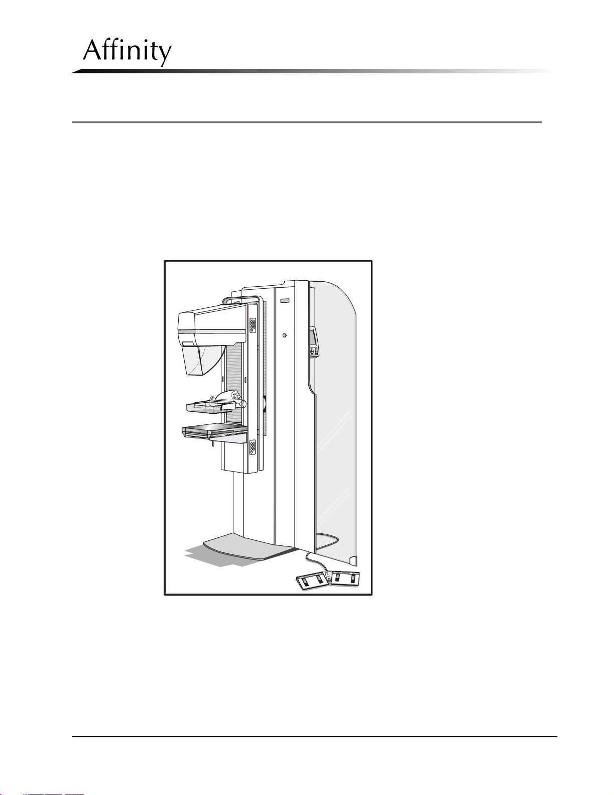
The LORAD Affinity is a dedicated mammography system which features automatic and
manual exposure modes, a compact control panel, and optional film labeling abilities
(Figure 1-1).
1.1 Intended Uses
The unit is intended to function in screening and diagnostic mammography procedures.
Service Manual
Chapter 1: General Information
Introduction
Figure 1-1: The Affinity System
P/N 9-500-0255 1-1
Page 22

Service Manual
Chapter 1: General Information
Safety
1.2 Required Tools and Equipment
Table 1-1 identifies the required tools and equipment for use during installation and
maintenance of the Affinity System.
Table 1-1: Required Tools and Equipment for Installation and Maintenance
• Standard Hand Tools (non-metric) • Oscilloscope—100 MHz (min) 2 channel
• Digital Multimeter (DMM) • Hex Wrench Set - standard
• Radiation Meter with probe
(Victoreen Model 600 or equivalent)
• Aluminum Filter Pack—Type 1100
(99.9% pure)
• High-Voltage Adapter Cable
(L
ORAD PN 2-425-3015)
• ACR Mammography Accreditation Phantom
(ACR MAP) (Nuclear Associates #156 or equivalent)
• PMMA Acrylic (or BR-12) - 0.5 cm thick (1 ea)
• PMMA Acrylic (or BR-12) - 1.0 cm thick (1 ea) • Light/X-ray Field Template (PN 3-405-8010)
• PMMA Acrylic (or BR-12) - 2.0 cm thick (4 ea) • Light Field Alignment Bars (PN 9-060-0173)
• Densitometer
• Image Receptor Phantom Tool—Cassette Simu-
lator (PN 9-060-0403)
• Loctite, 242 Blue (PN 2-580-0506) • Scale/Force Gauge—1 - 50 lb (min)
• Light Meter—UDT Instruments - Model 351
• High-Voltage Divider—Ratio of 10,000:1 or
100,000:1 with output impedance of 1 kΩ
• mAs Meter—dual range
• Lead Shield/Blocker—Approximately 4.0 x 4.0 cm
• Aluminum Aperture for Light meter with 1.0 mm
aperture
• Tool, Field Service Belt Adjustment
(PN 9-061-0107)
• Resolution Line Pair Phantom
2.0 Safety
This portion of the manual details electrical, mechanical, and radiation safety, as well as
precautions concerning static electricity and magnetic media storage. The equipment
complies with IEC 601 (General, Collateral and applicable Particular Standards), UL 2601
and CSA 22.2601.1.
Hazardous Material Warning!
• The x-ray tube contains a beryllium window that should not be touched.
• Follow all local ordinances or regulations for disposal of the x-ray tube.
• The x-ray tube covers and the image receptor contain lead that should not be touched.
• Follow all local ordinances or regulations for disposal of these covers.
Note… The Affinity does not contain any mercury or latex in its construction.
2.1 Electrical Safety
The equipment is designed to comply with IEC 601-1, UL 2601, and CSA 22.2601.1.
The Affinity is classified as CLASS I, TYPE B permanently connected equipment as per IEC
601-1. There are no special provisions to protect the system from flammable anesthetics or
ingress of liquids. However, the footswitches are splash-proof as per IPX6 or better.
1-2 P/N 9-500-0255
Page 23
Service Manual
Chapter 1: General Information
Safety
Emergency OFF switches are provided in compliance with IEC 601-2-32. Each of these
switches
disables power to the entire system.
WARNING! LETHAL voltages are present within the interior of the unit.
Use extreme caution to avoid contacting, directly or indirectly
(through tools), any connector pins, terminals, or test points.
Remove all jewelry before working on the unit, and avoid
wearing loose fitting clothing.
Warnings:
2.2 Interlocks
In addition to the Emergency OFF switches, the Affinity Series contains several safety
interlocks. These interlocks are as follows:
• C-arm Movement Interlock - When the C-arm encounters an obstruction during
travel, this interlock engages to immediately stop vertical travel and disable all Carm vertical movements (except C-arm UP) until the obstruction is cleared. C-arm
movement is also prohibited when compression force exceeds 50 N (12 lb).
• Automatic Compression Release Interlock - Installing a Localization Paddle disables
the compression release function, including automatic compression release (if
enabled).
• Early Release Interlock - When the x-ray exposure switch is released prior to the end
of the exposure, this interlock causes immediate termination of the exposure.
• Cassette Sense Interlock - When the system does not detect a cassette in the Bucky,
or if the cassette is not ejected after an exposure, this interlock prevents x-ray exposure.
• Aperture Interlock - This function detects the aperture and image receptor that is
installed and prevents x-ray exposure if an incompatible aperture/image receptor
combination is detected.
• Mirror/Filter Interlock - This interlock prevents x-ray exposure when the Light Field
Mirror and/or the Filter is not positioned correctly.
• Relay Interlock - This interlock prevents x-ray exposure when there is a failure of the
Power ON indicator or the X-ray Exposure indicator.
Only qualified electronic technicians who are certified and experienced in the maintenance and repair of high voltage x-ray equipment
should attempt to service this equipment.
Never perform service alone. Only service this equipment in the company of someone who is capable of rendering aid should an accident
occur.
2.3 Mechanical Safety
The equipment is designed to comply with the requirements of IEC 601-1, UL 2601, and
IEC 601-2-32, in that the following conditions exist:
• The C-arm rotation brake remains locked upon loss of electrical power (fail safe).
P/N 9-500-0255 1-3
Page 24

Service Manual
Chapter 1: General Information
Safety
• Automatic compression release (decompression) is disabled when a localization
paddle is installed.
• C-arm Force Limit is reached. The downward motorized movement of the C-arm is
limited to a force of 154 N, +
2.4 Radiation Safety
The unit’s radiation safety is designed to comply with all requirements of 21CFR Part 1020,
IEC 601-2-7, and IEC 601-1-3. The shield is rated for a 0.5 mm Pb (lead) equivalence. To
ensure radiological protection, restrict access to the unit in accordance with local
regulations.
The exposure duration is limited by the following normal conditions:
• The manual mAs timer
• The Automatic Exposure Control circuits
The exposure duration is also limited by the following abnormal conditions:
• Premature release of the x-ray exposure switch
• Exceeding the preset “back-up time”
• The independent safety hardware back-up timer
• Detection of a generator fault
44 N (35 lb, +10 lb).
1-4 P/N 9-500-0255
Page 25

3.0 Unit Description
The three major hardware components of the Affinity Series are:
• the Gantry
• the C-arm
• the Control Panel
The following paragraphs briefly describe each of the major hardware components.
3.1 Gantry and C-Arm
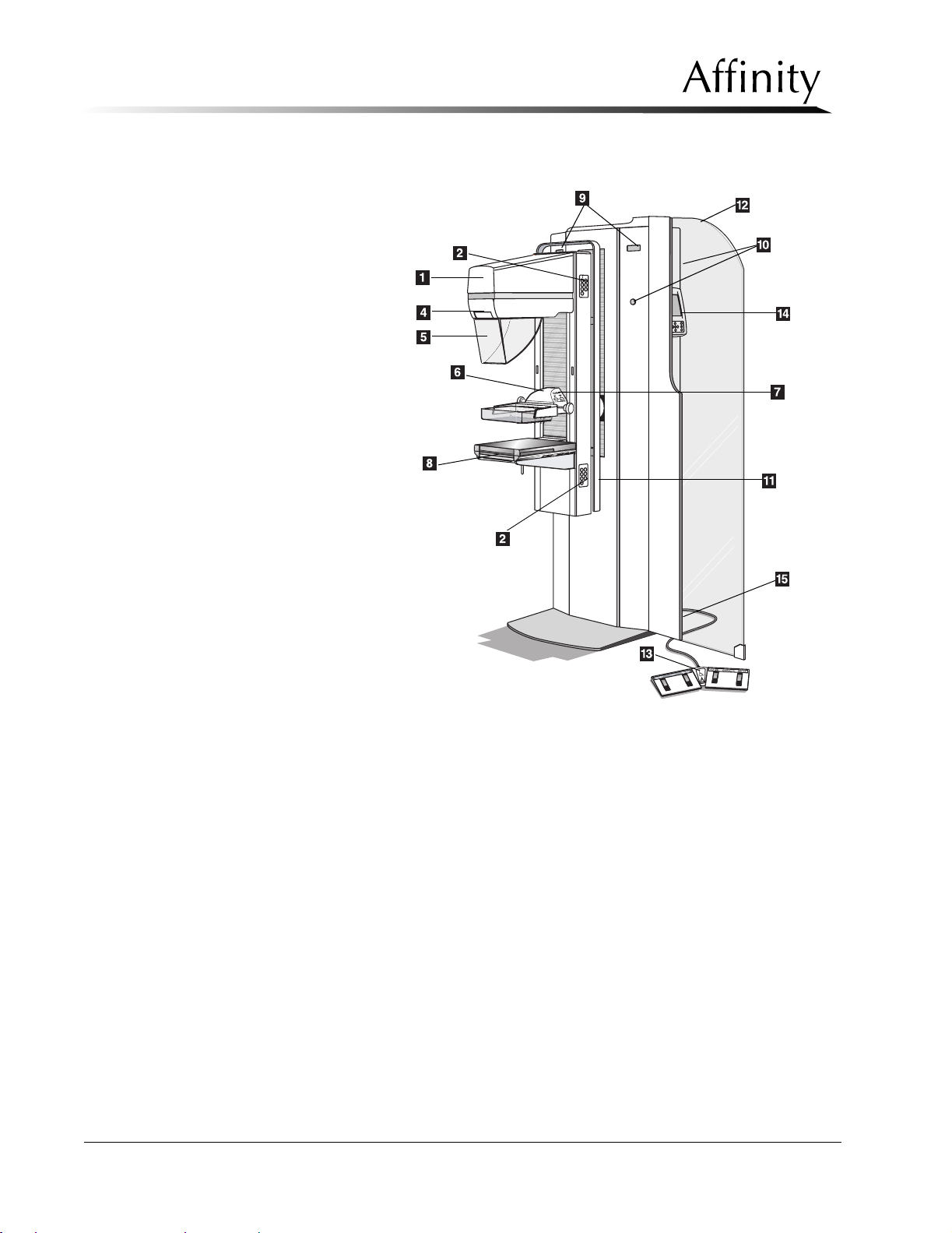
Refer to Figure 1-2 throughout the following. The Gantry houses the electronics which
produce high voltage at the energy levels needed for mammography. The mechanical
assemblies which position the C-arm (height and rotation), the input transformer, the
emergency OFF switches and most of the system electronics are also in the Gantry. LED
readouts on the left and right side of the Gantry show the C-arm angle.
The Gantry also supports an externally mounted radiation shield that protects the operator
from exposure during the exam, and houses the input power connector panel and
Footswitch receptacles.
Service Manual
Chapter 1: General Information
Unit Description
The C-arm is made up of the following major assemblies:
• X-ray Tubehead
• Compression Device
• Image Receptor Support Device
A pivot mechanism connects the C-arm to the Gantry. Pushbutton switches on each side of
the C-arm, and on the tubehead, control C-arm movement, Compression Release,
Compression up/down, and the light field lamp. The design of the C-arm permits
examination of standing, sitting or recumbent patients.
P/N 9-500-0255 1-5
Page 26
Service Manual
Chapter 1: General Information
Unit Description
Legend for Figure 1-2
1. Tubehead
2. 7-Button Keypad (total of four,
two on each side)
3. 3-Button Keypad (not shown,
located on Top of Tubehead)
4. Aperture Slot
5. Face Shield
6. Compression Device
7. Compression Thickness/Force
Displays
8. Image Receptor Support Device
9. C-Arm Angle Display (total of
two, one on each side)
10. Emergency OFF Switch (total of
three, two on front of Gantry, and
one on rear)
11. Patient Handle
12. Radiation Shield
13. Footswitch
14. Control Panel
15. X-ray Footswitch (not shown,
mounted on Gantry base plate
behind Radiation Shield)
Figure 1-2: Affinity Gantry and C-Arm
1-6 P/N 9-500-0255
Page 27
3.2 Control Panel
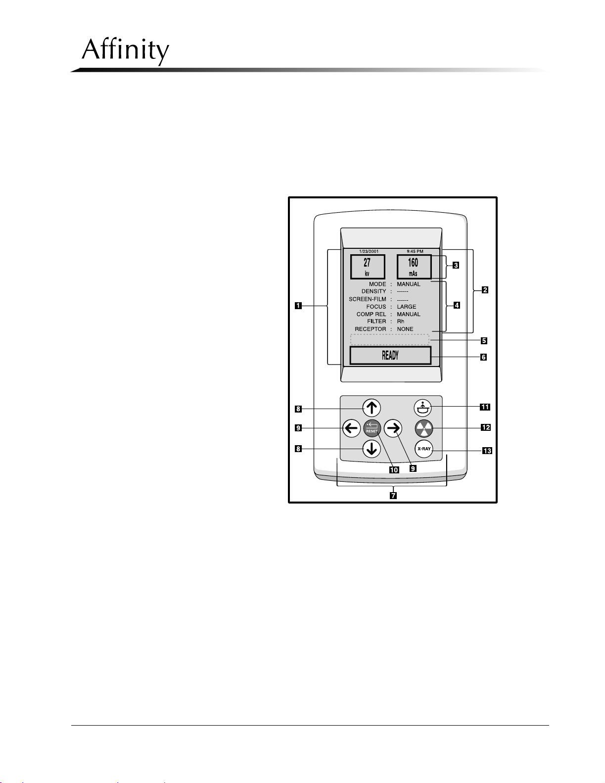
The Control Panel (Figure 1-3) is a compact user interface that mounts to the side of the
Gantry, or at a remote location. The control panel is an interactive device consisting of a
Function Keypad and an LCD Display Window. It is used to set exposure techniques and
parameters, provide operator instructions, display alert and system status messages, and
initiate x-rays.
Legend for Figure 1-3
1. LCD Display Window
2. Exposure Parameters Area
3. Exposure Factor Selection Area
4. Exposure Parameter Selection
Area
5. Message Area
6. Status Area
7. Function Keypad
8. Scroll Keys
9. Change Keys
10. Reset Key
11. Compression Release Key
12. Exposure Indicator
13. Exposure Enable Key
Service Manual
Chapter 1: General Information
Unit Description
Figure 1-3: Affinity Series Control Panel
P/N 9-500-0255 1-7
Page 28
Service Manual
Chapter 1: General Information
Compliance Data
4.0 Compliance Data
The Mammography System conforms to all applicable FDA regulations. Labels addressing
the certifiable components are fixed to the unit at several points (refer to Figure 1-4). The
main identification label containing the equipment model number and serial number is near
the input power receptacle on the Gantry.
The serial number is used to track units for warranty and service purposes, and will be
requested should it become necessary to contact L
ORAD regarding the machine.
Note… The L
ORAD Bucky devices (18 x 24 cm and 24 x 30 cm) are certified
components that do not have to be reported on form FDA 2579 (Ref BRH:
Doc MA3499).
4.1 Compliance Statement
The manufacturer states that this device conforms to:
• Medical Device Directive 93/42/EEC Annex II.
• ISO 9001:1994, EN 46001 1993, ISO 13485
• IEC 601-1: Safety Requirements For Medical Electrical Systems
• IEC 601-1-2: Electromagnetic Compatibility
• IEC 601-1-3: General Requirements for Radiation Protection
• IEC 601-1-4: Safety of Programmable Electrical Medical Systems
• IEC 601-2-7: Safety Of High Voltage Generators
• IEC 601-2-28: Safety of X-ray Source Assemblies
• IEC 601-2-32: Safety of Associated Equipment
• IEC 601-2-45:2001: Safety of Mammographic Equipment
• FDA, 21 CFR [Parts 820, 900 and 1020]
• UL 2601-1: General Requirements for Safety
• CSA 22.2. No. 601.1: General Requirements for Safety
4.1.1 Remote Indication of the Ready State
If it is desired to indicate the “Ready State” at a location other than at the operator
panel, such as at the room door, a signal is available on the Host Microprocessor
Board (PN 1-003-0493), connector AJ31 between pins 5 (+5 V, active high) and 9
(ground). This signal is a low level logic signal that drives the relay to provide remote
activation of an indicator lamp (LED).
Caution:
1-8 P/N 9-500-0255
Do not use external power supply to drive the output.
Page 29
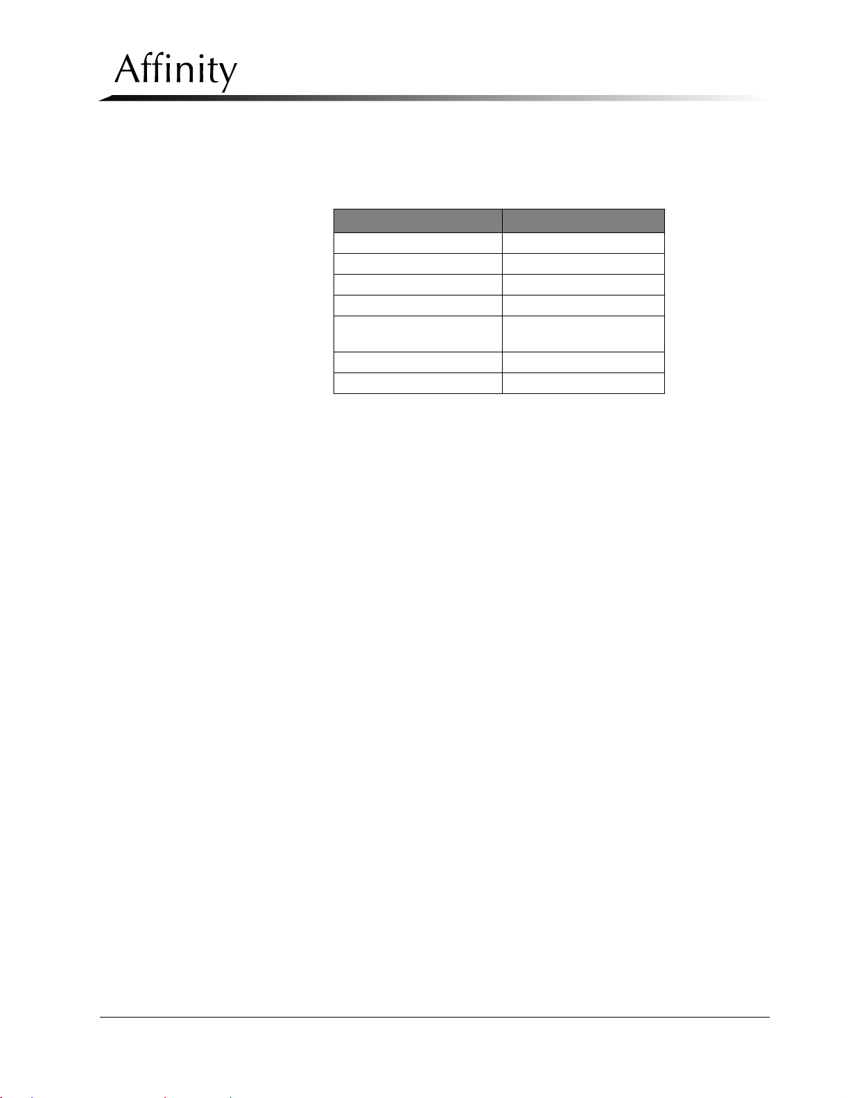
4.2 Certifiable Components
These components are identified using individual serial numbers in addition to the serial
number of the overall L
ORAD unit.
Item Manufacturer
X-ray Tube Varian (IM-113R)
Beam Limiting Device L
High-Voltage Generator LORAD
X-Ray Control LORAD
Image Receptor Support
Device
Bucky 18 x 24 cm LORAD
Bucky 24 x 30 cm LORAD
Service Manual
Chapter 1: General Information
Compliance Data
ORAD
LORAD
P/N 9-500-0255 1-9
Page 30
Service Manual
Chapter 1: General Information
Compliance Data
4.3 Location of Labels
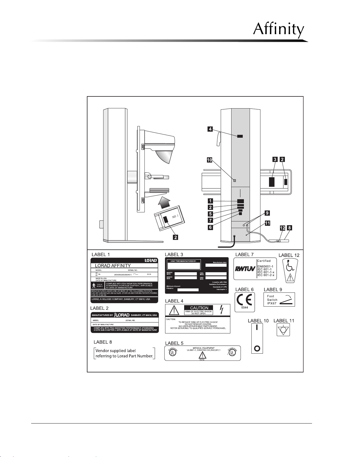
Compliance labels and nameplates are positioned appropriately on the Affinity Series
mammography unit. Nameplates contain the unit’s serial number and manufacturing date.
When calling in for support, please reference the system serial number noted on Label 1.
Figure 1-4: Compliance Label Locations
1-10 P/N 9-500-0255
Page 31
Chapter 2: System Installation
1.0 Room Planning
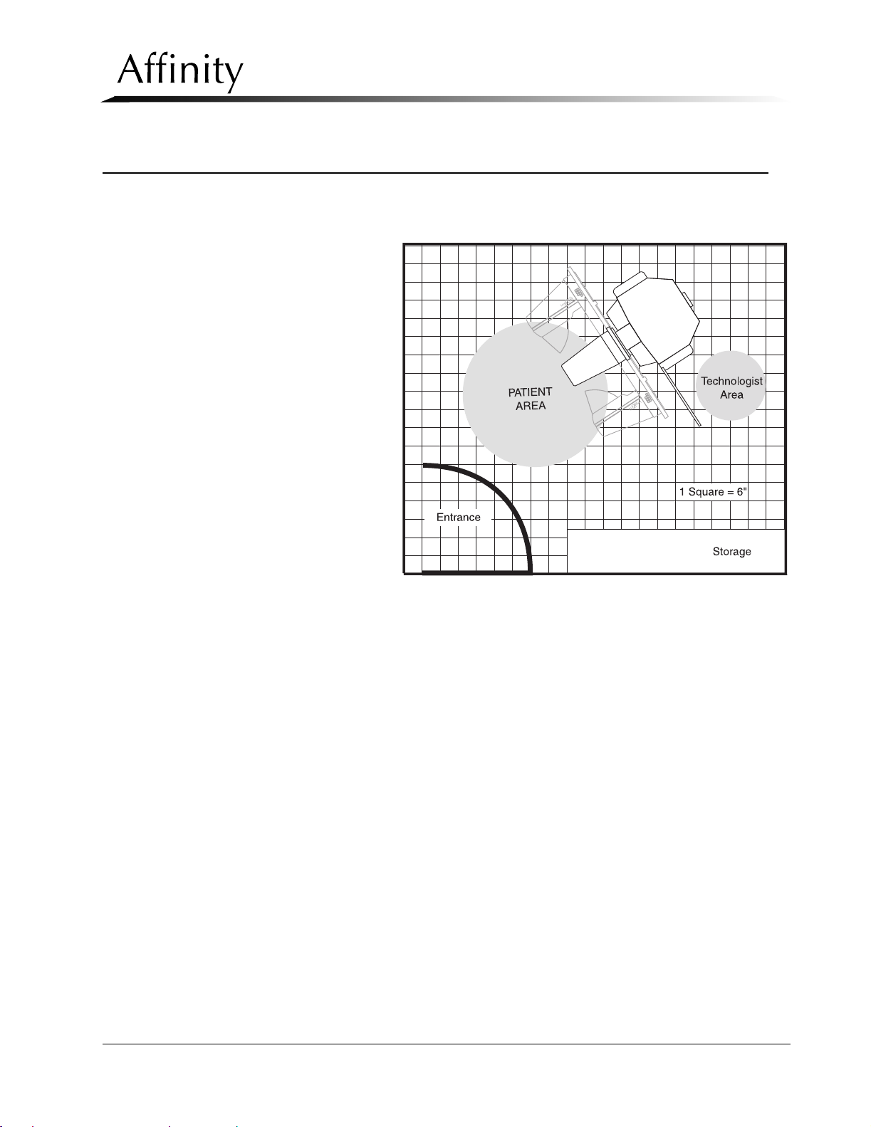
The exam room layout
should be pre-planned
before the arrival of the
Affinity. Check the height
and width of the exam
room door to ensure it
will accommodate the
mammography machine
(70" high, 30" wide
minimum).
Other factors to consider
when planning the room
layout are:
Service Manual
Chapter 2: System Installation
Room Planning
• C-arm clearances: The C-arm
requires 55" (minimum) to accommodate rotation,
and 89” (minimum) to accommodate raising
the C-arm to its
upper limit. When planning the room layout, take into consideration extra wall and
ceiling clearance for movement and handling of C-arm controls.
• Radiation Shield clearances: The protective radiation shield extends 24” from the
side of the unit. The room layout must provide enough space to allow the user to
maneuver around the radiation shield when it is attached.
• Movement clearance: Always take into consideration space allocation for patient
and technologist movement. Avoid obstructions in the room that may hinder access
to the unit controls or the patient.
• Storage: Provide convenient storage for patient records, film cassettes, and system
accessories. If accessory storage is not possible within the exam room, make
arrangements for safe storage close by.
• Recommended Power Source Requirements: Refer to Appendix A, Section 1.1-Electrical Input Specifications.
Figure 2-1: Example Room Layout
P/N 9-500-0255 2-1
Page 32
Service Manual
Chapter 2: System Installation
Unpacking Instructions
2.0 Unpacking Instructions
The following sections detail receiving and unpacking instructions, and inspections required
prior to installing the Affinity Series Mammography Unit.
2.1 Receiving Instructions
The Affinity Series Mammography Unit is shipped in containers that hold the following:
• the Gantry
• the Accessories
• the Radiation Shield
Upon receipt, perform the following before opening the containers:
• Inspect each container for damage.
• Note any damage on the shipping manifest.
• Notify L
2.2 Un-Crating the Unit
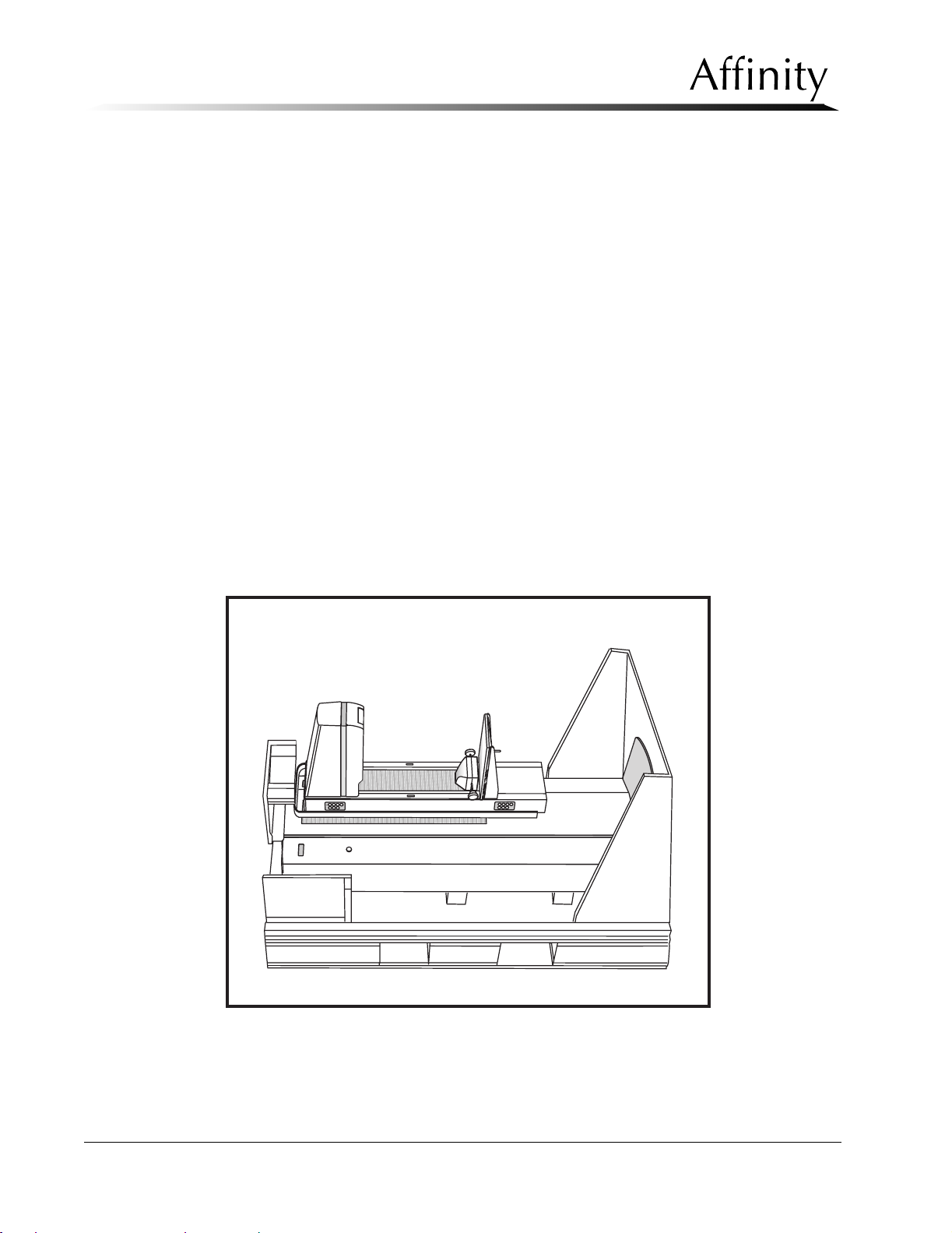
The Affinity Gantry is crated and shipped in a prone position (see Figure 2-2).
ORAD of any external shipping damage that may have occurred.
Be sure to have the necessary machinery and personnel available to move heavy medical
equipment safely.
Figure 2-2: Un-Crating the Gantry
Un-crate the unit as follows:
1. Cut the retaining straps that secure the container top to the shock-mounted wooden pallet. Lift the container top off the unit.
2-2 P/N 9-500-0255
Page 33
Service Manual
Chapter 2: System Installation
Unpacking Instructions
2. Carefully remove all shipping materials (foam padding, tie-downs, straps, shipping wrap,
etc.) from the unit and pallet. Lift any accessory boxes from the pallet.
3. Open all crates and boxes and check their contents against the packing list and sales
order.
Note… If there is a discrepancy between the contents and the packing list or sales
order, contact L
future installation, use the original packaging materials.
4. Inspect each item for damage, then safely store them near the exam site.
ORAD immediately. If it is necessary to re-pack any items for
Caution:
Notes… If shipping damage is of a concealed nature, contact the carrier as soon as
To prevent damage, do not store the radiation shield flat. Avoid damaging
the Radiation Shield by impact or scratching.
such damage is found, and request an inspection for shipping damage.
Normally, any claims for shipping damage must be completed within 15
days of receiving the shipment.
Warning: Never pull on the C-arm as the unit is top heavy. To prevent injury
to personnel and/or damage to equipment, care must be taken
when un-crating the unit.
5. While still in the loading area, carefully move the pallet into an upright position.
6. Remove the top collar securing the unit to the pallet. Using the installed dolly, carefully
roll the unit off the pallet.
7. Transport the unit, on the installed dolly, from the loading area to the exam area for
installation.
8. Remove the 4 bolts securing the unit to the dolly. Carefully maneuver the unit off the
back end of the dolly, slide the dolly out and position the unit in the area of installation.
9. Return the dolly to L
ORAD as per the shipping instructions posted on the dolly.
P/N 9-500-0255 2-3
Page 34
Service Manual
Chapter 2: System Installation
Unit Installation
3.0 Unit Installation
The following sections detail setting up, positioning, and installing the Affinity Series
Mammography unit in the exam room.
As appropriate, install the Affinity Series Mammography unit in the exam room as per the
following general sequence of steps:
Note… Thoroughly read all procedures prior to starting.
1. Position the Gantry in the area of the exam room where the unit will be permanently
installed. Ensure the Gantry is positioned for easy access to the rear of the unit.
2. Perform the following installation procedures in the order given.
• Input Power Configuration—Section 3.1
• Power Cable Connection—Section 3.2
• Remote X-ray ON/Power ON Light Connection—Section 3.3
• Control Panel Installation—Section 3.4
• Securing Unit in Position—Section 3.5
• Installing the Unit Accessories—Section 3.6
• Initial Start Up Procedures—Section 3.7
• Final Operational Setup—Section 3.8
Note… Do not replace any covers or panels until told to do so.
3.1 Input Power Configuration
The isolation transformer must be configured to match the power source at the site. This
portion of the manual details the steps to properly configure and connect the mammography
unit to a voltage source.
Before connecting the unit to a power outlet, verify the source voltage as follows:
1. Measure the voltage at the outlet receptacle.
2. Inquire as to any history of voltage fluctuations or voltage-related problems that have
occurred in other equipment at the site.
3. Check the ground impedance using the following formula:
V–
V
NL
R
-------------------------=
Where:
R = Ground Impedance
V
= Voltage at no load
NL
= Voltage at full load (32 kV, 100 mA)
V
FL
I
MAX.L
Ground Impedance must be no more than:
0.20 Ω at 208, 220, 230, 240 V
0.16 Ω at 200 V
FL
I
MAX L•
= Current at full load
~
TAP
~
TAP
2-4 P/N 9-500-0255
Page 35
Service Manual
Chapter 2: System Installation
Unit Installation
After determining the input voltage range, verify the unit’s isolation transformer is correctly
set (re-configure as required).
The following explains how to access the input power assembly chassis and re-configure the
isolation transformer taps to match the source voltage measured previously.
1. Flip the circuit breaker on the rear of the Gantry down (OFF).
2. Remove the Gantry Upper Rear panel as per Chapter 6, Section 2.1.2. Set the cover
aside.
3. Remove the Rear Connector panel and shroud as per Chapter 6, Section 2.1.3. Pull the
panel slightly away from the unit, then let it hang by the attached wiring harness.
4. To gain access to the input power assembly chassis, remove the Lower Rear panel as per
Chapter 6, Section 2.1.4, Steps 1 through 3. The isolation transformer is mounted on the
lower shelf of the input power assembly chassis.
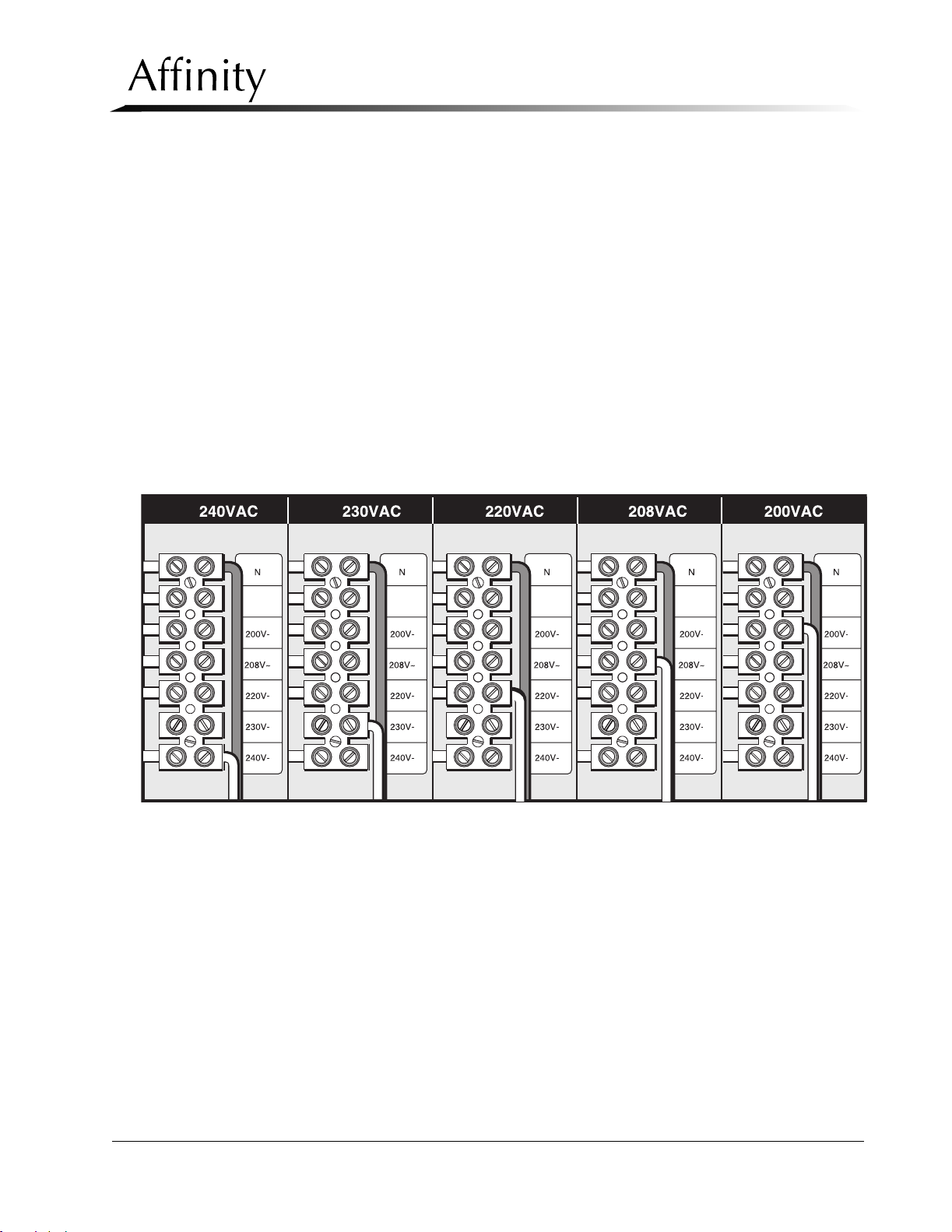
5. Configure the input wiring to tap the transformer so that it matches the previously mea-
sured source voltage (refer to Figure 2-3).
Figure 2-3: Isolation Transformer Taps
3.2 Power Cable Connection
The power cord will need to be hardwired into the power source. This should be done by a
certified electrician.
P/N 9-500-0255 2-5
Page 36
Service Manual
Chapter 2: System Installation
Unit Installation
3.3 Remote X-ray ON/Power ON Light Connection
The Affinity System provides the user with the ability to operate remote lights which
indicate when the System is ON and when X-rays are being taken. These lights are
normally installed above the door to the exam room. Installation should be done by a
certified electrician. The relay contacts provided are rated as follows:
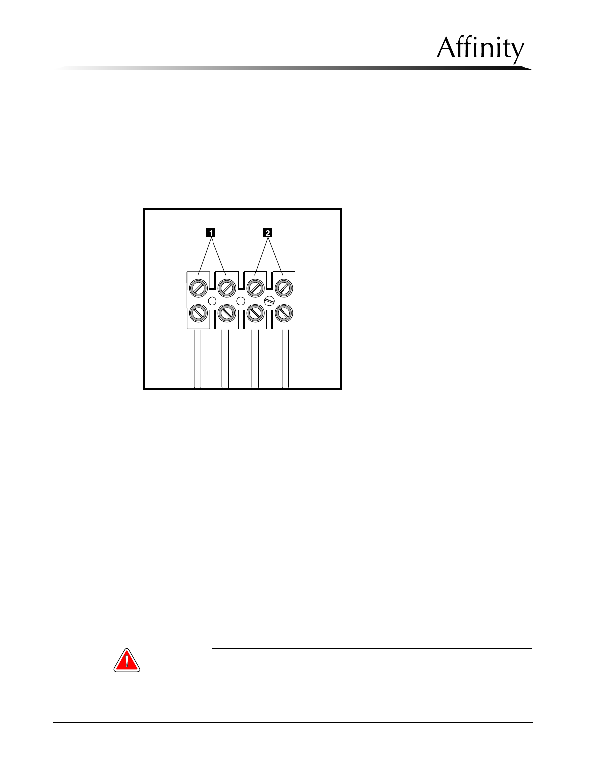
Legend for Figure 2-4
1. X-ray ON Lamp Connections
2. Power ON Lamp Connections
Figure 2-4: User Lamp (X-ray ON/Power ON) Connections
• 10 Amp 250 VAC (normally open)
• 10 Amp 30 VDC (normally open)
Connections are made on the removable power supply distribution assembly (Figure 2-4),
located on the input power assembly chassis, as follows:
1. Locate the removable power distribution assembly and connect the remote X-ray ON
and Power ON cables to the terminal board as shown in Figure 2-4.
2. Complete the remote cables and light installation following local guidelines.
3. Replace the Gantry lower rear, upper rear and rear connector panels. Do not replace
rear connector panel shroud at this time.
3.4 Control Panel Installation
The Control Panel is either mounted to the side of the Gantry or remotely located. Follow the
instructions appropriate for the site’s required configuration.
3.4.1 Control Panel to Gantry Installation
For Gantry mount configurations, the Affinity is shipped with the Control Panel
already attached to the right side cover.
Warning: For those units with the Control Panel mounted to the Gantry, the
radiation shield is required. The shield is installed following
completion of initial startup procedures.
2-6 P/N 9-500-0255
Page 37
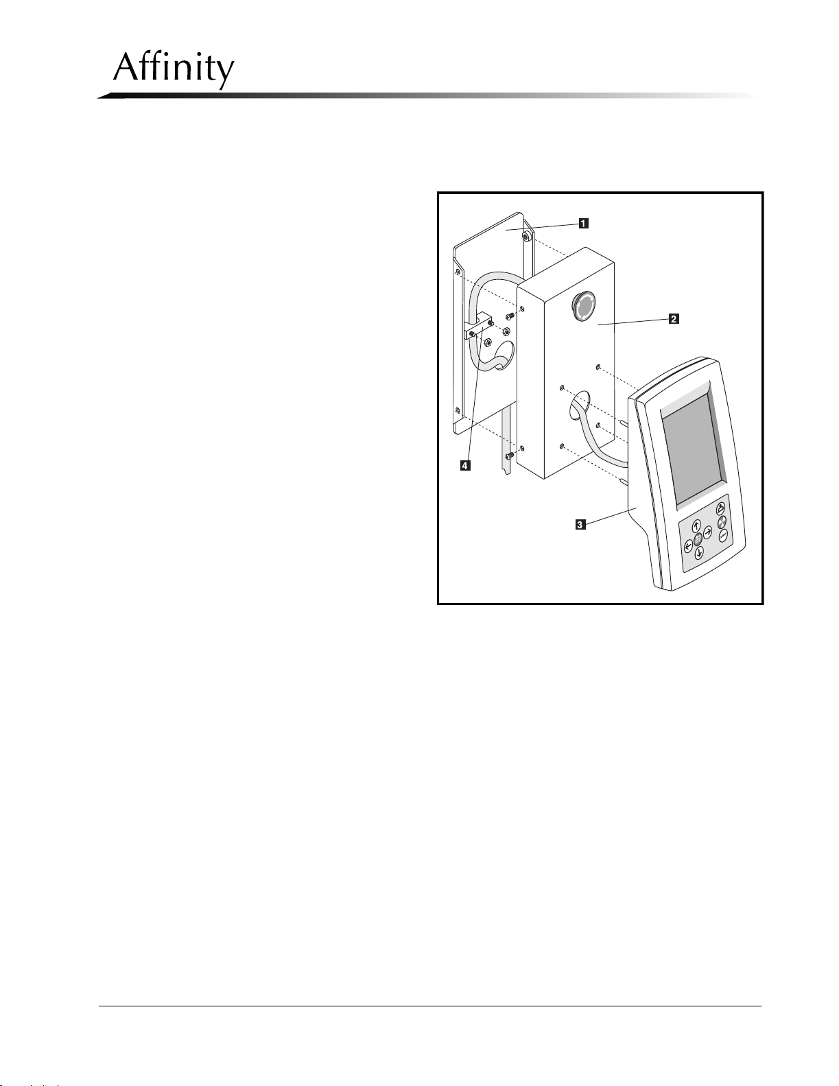
3.4.2 Control Panel Remote Location Installation
For units that are configured for remote operations, the Remote Control Panel Kit (3000-5042) is included (refer to Figure 2-5).
The kit consists of the
following:
• Housing and Housing Mount
• Control Panel and
EMO Switch Harness
(2 50 ft cables)
• EMO Switch - Emergency Stop Switch
Service Manual
Chapter 2: System Installation
Unit Installation
Figure 2-5: Remote Control Panel Installation
Install the Remote Control Panel as follows:
1. Mount the Control Panel housing bracket (Figure 2-5, Item 1) to the wall (or
other mounting apparatus) in the remote location using the supplied hardware.
2. Route the Control Panel and EMO Switch harness through the strain relief
(Figure 2-5, Item 4), then out the access hole in the housing bracket. Make all
the appropriate harness connections, then tighten the strain relief.
3. Mount the Control Panel housing (Figure 2-5, Item 2) to the housing bracket
using the supplied hardware. Note that an EMO switch is mounted on the
housing.
4. Align the tabs on the rear of the Control Panel (Figure 2-5, Item 3) with the slots
on the housing. Insert the tabs into the slots and slide the Control Panel down to
lock in place.
5. Connect the end of the Control Panel interconnect cable to the Remote Control
receptacle (Figure 2-6, Item 8) on the rear connector panel.
6. Connect the Emergency Stop Switch interconnect cable to the Emergency Stop
receptacle (Figure 2-6, Item 9) on the rear connector panel.
P/N 9-500-0255 2-7
Page 38
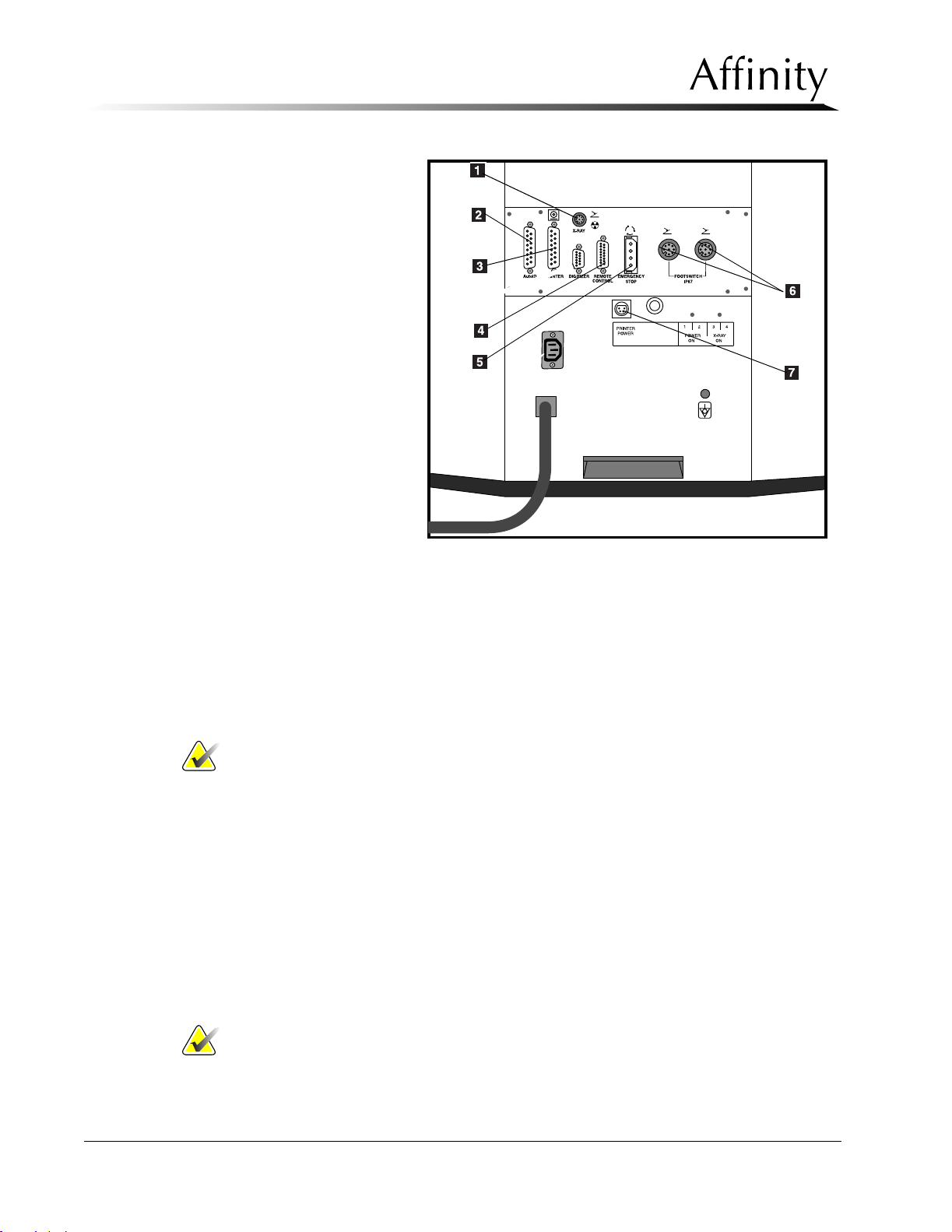
Service Manual
Chapter 2: System Installation
Unit Installation
Legend for Figure 2-6
1. Exposure Footswitch
Connector
2. Rapid I.D. Receptacle
3. Printer/AutoFilm I.D.
Connector
4. Remote Control
(remotely located Control Panel
5. Emergency Stop
6. Footswitch Connectors
7. AutoID/Rapid ID
Power Outlet
Figure 2-6: Rear Connector Panel (Shroud removed) and
Lower Rear Panel Connections
3.5 Securing Unit in Position
1. Remove left and right Gantry side panels as per Chapter 6, Section 2.1.1.
2. Carefully move the unit into its pre-designated final position. Ensure the circuit breaker
and rear panels are accessible.
3. Mount unit to the floor in accordance with site specification drawings and/or local
building codes.
Note… Do not replace left and right side panels at this time.
3.6 Installing the Unit Accessories
This section provides instructions for installing the following accessories:
• Exposure Footswitch
• Dual Function Footswitch(es)
• Film Labeling Devices
3.6.1 Exposure Footswitch
When the exposure footswitch is installed on a machine, you must push both the
exposure footswitch and the x-ray button on the control panel at the same time to
initiate and finish an exposure.
Install the exposure footswitch as follows:
Note… The exposure footswitch will be received already mounted on the exposure
footswitch mounting bracket.
2-8 P/N 9-500-0255
Page 39
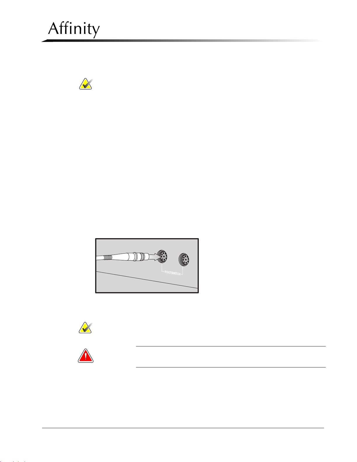
Service Manual
Chapter 2: System Installation
Unit Installation
1. Secure the exposure footswitch mounting bracket to the Gantry base plate using
two screws (supplied) on the right side of the Gantry.
Note… When the Gantry right side cover is installed, the exposure footswitch will
be positioned below the Control Panel).
2. Connect the exposure footswitch cable to the x-ray connector (Figure 2-6, Item
5).
A. Align the key in the footswitch connector to the keyhole in the receptacle.
A. Push the connector straight in until it stops.
3. Locate DIP switch (S2) at the lower right side of the Host Microprocessor board
(Gantry right-side panel removed). Enable the X-ray Footswitch by setting S2
switch 3 to OFF.
3.6.2 Dual Function Footswitch(es)
A dual-function footswitch provides C-arm and Compression Up or Down
movement. Normal system configuration consists of one footswitch with an optional
second footswitch. Two jacks (on the lower rear of the Gantry) provide connections
for the Footswitch(es). To connect the Footswitch(es), perform the following:
1. Connect the Footswitch(es) connector to the left and/or right Footswitch receptacles (Figure 2-6, Item 6) on the Gantry connection panel.
2. Align the key in the footswitch connector to the keyhole in the receptacle
(Figure 2-7).
Figure 2-7: Connecting a Footswitch
3. Push the connector straight in until it stops.
Note… Either Footswitch can be connected to either Footswitch receptacle.
4. Position the footswitch in the desired location on the floor below the C-arm.
WARNING: Position the Footswitch(es) in such a way as to prevent accidental
activation by patients or operators.
P/N 9-500-0255 2-9
Page 40

Service Manual
Chapter 2: System Installation
Unit Installation
3.6.3 Connecting Film Labeling Devices
The Affinity will accept the following film labeling devices:
• AutoFilm I.D.
• Label Printer
The AutoFilm I.D. is used to place photographic labels directly on the film. The
Label Printer is used to create self-adhesive labels that are manually placed on each
film.
Note… The film labeling device (AutoFilm I.D. or Printer) must be installed so that it
AutoFilm I.D.
Refer to the AutoFilm I.D. User’s Guide (PN 9-500-0078) for installation and
operating procedures.
Label Printer
The Label Printer is used to print out a self-adhesive label containing the exposure
information. When connected and on-line, the Printer immediately prints a label
after each exposure.
1. Insert the one end of the Printer cable into the receptacle on the rear of the
2. Connect the other end of the printer cable to the Printer receptacle (Figure 2-6,
is situated at least 2 meters (approximately 6 feet) from the patient.
Printer.
Item 2) on the rear of the Gantry.
3. Plug the Printer power cord into the power receptacle on the rear of the Printer,
then plug the opposite end into the Printer Power outlet (Figure 2-6, Item 4) on
the rear of the Gantry.
3.7 Initial Start Up Procedures
At this point in the Affinity Series Mammography System installation procedures, the unit
should be permanently mounted in position with all power and applicable accessory
connections made (except for radiation shield). The rear panels should all be installed with
the exception of the rear connector panel shroud and the left and right cover panels.
3.7.1 Remote X-ray ON Light Configuration
When installed, the remote X-ray ON light can be configured to define whether it
will be ON only during the X-ray period or throughout the entire boost and X-ray
periods. Configure it as follows:
1. Locate the Host Microprocessor board on the Gantry right side (cover previously removed). Refer to Chapter 6, Figure 6-1 for board location and identification.
2. Install jumper on JP7 as follows:
• For light ON only during X-ray period, install jumper between positions 1 and 2.
• For light ON during Boost and X-ray period, install jumper between positions 2
and 3.
2-10 P/N 9-500-0255
Page 41

3.7.2 Initial Power Up
Prior to initial power up of the system, verify the input panel has been tapped to
match the input power source.
1. Perform the following pre-power up checks before applying power to the sys-
tem:
A. Verify that all three Emergency OFF switches are reset (four switches if con-
trol panel is remotely installed) by turning them clockwise.
B. Be sure the room is clear of obstructions.
C. Correct all discrepancies before applying power.
D. Position the radiation shield (if applicable) on the unit (you will not be able
to secure the shield in place as the right side cover is removed at this point).
2. Apply power to the system as follows:
A. If a film labeling device is installed, apply power to the device (AutoFilm
I.D.). The AutoFilm I.D. has a “rocker” type power switch.
E. Flip the circuit breaker on the rear of the Gantry up (ON position). The back
light of the display is indication that power is applied.
Service Manual
Chapter 2: System Installation
Unit Installation
F. The Control Panel (refer to Chapter 3, Figure 3-1, Item 9) will display a mes-
sage informing the user that internal checks are being performed.
G. Verify that the Control Panel displays the Run Mode screen after power up.
H. If the AutoFilm I.D. is installed, verify that the Patient Information Screen is
displayed. Refer to the AutoFilm I.D. User’s Guide.
Note… If the system detects a fault condition during startup, an appropriate
message will appear on the screen. The power up sequence is suspended
until the condition that caused the alert is remedied. Refer to the Alert
Codes listed in Chapter 5, Section 3.2, Table 5-2.
3. Perform the Post Power Up Checks as per Chapter 3, Section 2.3.
3.7.3 Setting Operational Parameters
Upon completion of initial power up procedures, the following calibration and
alignment procedures must be performed to establish site preferences for system
operations.
• Set User Defaults—Chapter 3, Section 4.0.
• Calibration Procedures—Chapter 4, Section 2.0.
• Performance Checks—Chapter 4, Section 6.0.
• X-ray and Light Field Check and Alignment Procedures—Chapter 4, Section 7.0.
3.8 Final Operational Setup
Upon completion of the calibration and alignment procedures, the following steps must be
performed to ready the system for operations.
1. Remove power to unit.
2. Place radiation shield (if applicable) out of the way.
3. Replace all covers and panels.
P/N 9-500-0255 2-11
Page 42
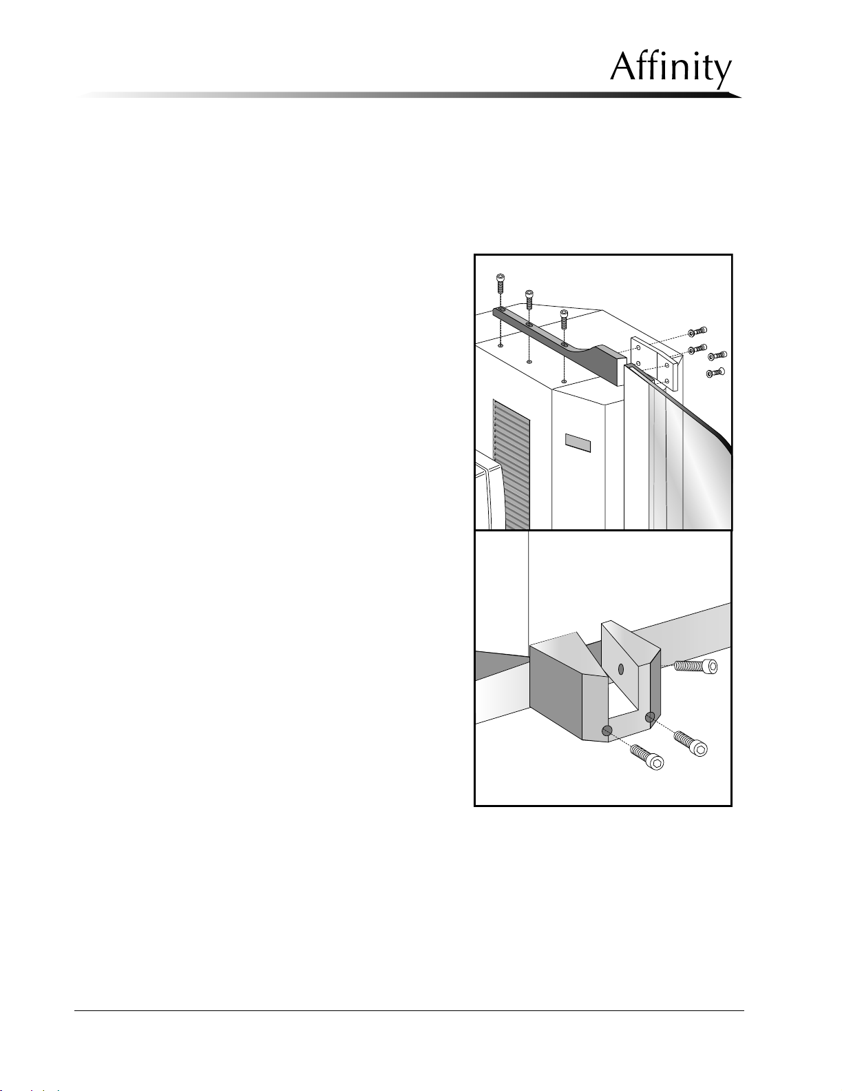
Service Manual
Chapter 2: System Installation
Unit Installation
4. Install the radiation shield (if applicable) as per Section 3.8.1.
Upon completing the above procedures, the system will be ready for normal operations.
3.8.1 Installing the Radiation Shield
The Radiation Shield mounts to the side of the Gantry. Once installed, the shield is
permanently open. Refer to Figure 2-8 throughout the following:
1. Install the radiation shield
2. While aligning the pins on the
3. Secure the radiation mounting
mounting bracket to the top of
the radiation shield using the
supplied hardware. To ensure
radiation shield is properly
aligned on the gantry, do not
tighten hardware at this time.
radiation shield mounting
bracket with their
corresponding holes on the top
of the gantry, position the
bottom of the Radiation Shield
in the lower mounting bracket
on the right side of the Gantry.
bracket to the top of the gantry
with the hardware provided.
4. While gently pushing radiation
shield flush with right side of
gantry, tighten the hardware
securing the radiation shield
mounting bracket to the top of
the radiation shield.
5. Secure the radiation shield to
the lower mounting bracket
with the hardware provided.
Figure 2-8: Installing the Radiation Shield
2-12 P/N 9-500-0255
Page 43
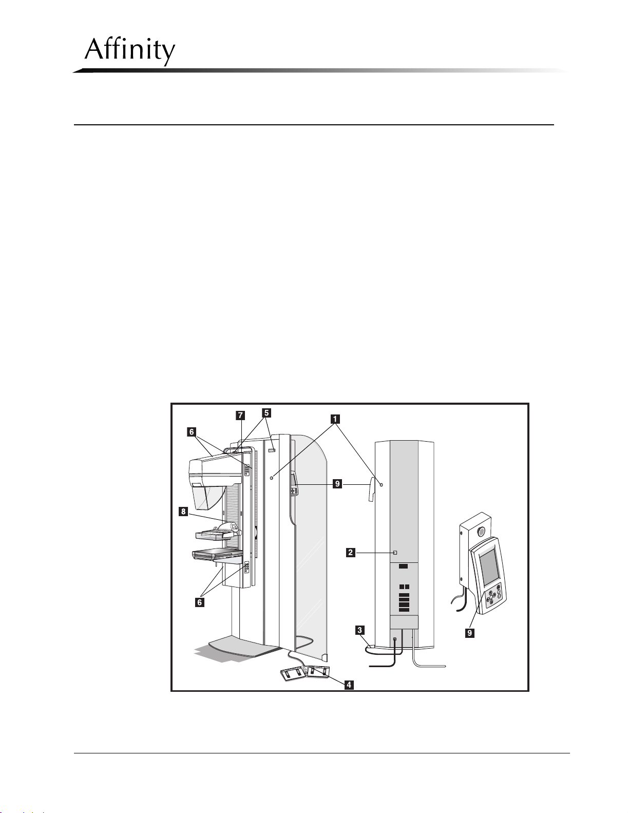
Chapter 3: Functional Checks/Setting Defaults
Controls and Indicators
Chapter 3: Functional Checks/Setting Defaults
1.0 Controls and Indicators
Figure 3-1 shows the location of the Affinity Series Controls and Indicators used throughout
this Chapter. For detailed information on the Affinity Controls and Indicators, refer to the
Affinity Series Operator’s Manual, PN 9-500-0246.
Legend for Figure 3-1
1. Emergency OFF Switches (EMO)—Two on front of Gantry, one on rear. (For those systems with the Remote Control Panel installed, a fourth EMO switch is located on the
control panel mounting block.)
2. Circuit Breaker
3. X-ray Footswitch
4. Dual Function Footswitch
5. Rotation Angle Display
6. C-Arm Controls 7-Button Keypad (two top, two bottom)
7. Tubehead Controls 3-Button Keypad
8. Compression Device
9. Control Panel
Service Manual
Figure 3-1: Affinity Controls and Indicators
P/N 9-500-0255 3-1
Page 44

Service Manual
Chapter 3: Functional Checks/Setting Defaults
System Power Up
2.0 System Power Up
2.1 Pre-Power Up Checks
Perform these pre-power up checks before applying power to the system:
1. Verify that all three Emergency OFF switches are reset (four switches if control panel is
remotely installed) by turning them clockwise.
2. Check the overall integrity of the mammography unit for open or loose panels, missing
hardware, and signs of damage.
3. Inspect the radiation shield for chips, cracks, breaks, and secure attachment.
4. Be sure the room is clear of obstructions.
5. Correct all discrepancies before applying power.
2.2 Power Up Sequence
Apply power to the system as follows:
Notes… Always perform the pre-power on checks detailed previously before
applying power to the unit.
Always correct discrepancies before turning the unit on and using it
clinically.
1. If a film labeling device is installed, apply power to the device (AutoFilm I.D.). The AutoFilm I.D. has a “rocker” type power switch.
2. Flip the circuit breaker on the rear of the Gantry up (ON position). The back light of the
display is indication that power is applied.
3. The Control Panel will display a message informing the user that internal checks are
being performed.
4. Verify that the Control Panel (Figure 3-1, Item 9) displays the Run Mode screen after
power up.
5. If the AutoFilm I.D. is installed, verify that the Patient Information Screen is displayed.
Refer to the AutoFilm I.D. User’s Guide.
Note… If the system detects a fault condition during startup, an appropriate
message will appear on the screen. The power up sequence is suspended
until the condition that caused the alert is remedied.
3-2 P/N 9-500-0255
Page 45
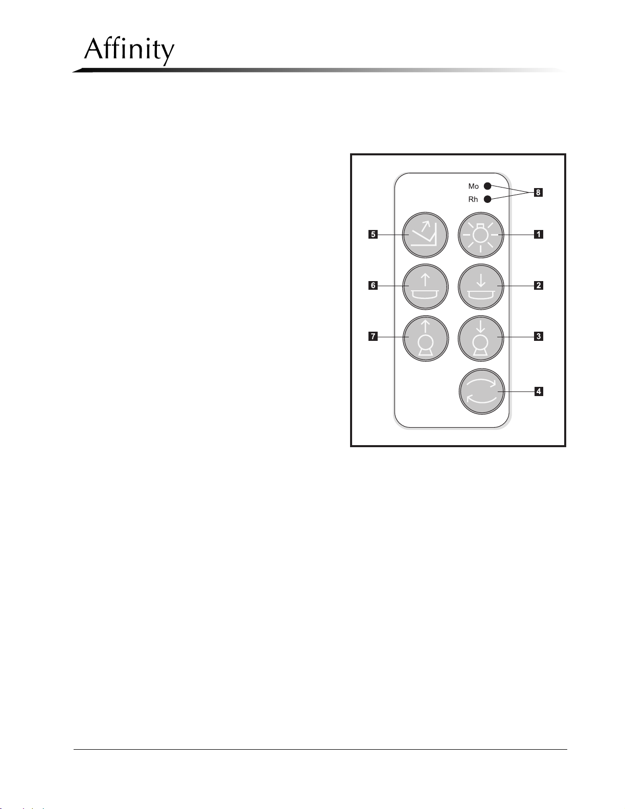
2.3 Post Power-Up Checks
After power is applied, perform the following checks to determine if the electro-mechanical
subsystems are functioning. Correct all discrepancies before releasing the unit to the user.
Legend for Figure 3-2
1. Light Field Lamp
2. Compression Down Switch
3. C-Arm Down Switch
4. C-Arm Rotation Release Switch
5. Compression Release Switch
6. Compression Up Switch
7. C-Arm Up Switch
8. Filter Type LED Indicators (Mo or Rh)
Service Manual
Chapter 3: Functional Checks/Setting Defaults
System Power Up
Figure 3-2: The C-arm Controls
P/N 9-500-0255 3-3
Page 46

Service Manual
Chapter 3: Functional Checks/Setting Defaults
System Power Up
Table 3-1: Post Power-Up Checks
Functional Check Button Procedure
C-Arm Controls—
Perform this test for
each of the four 7-button keypads on the Carm.
1. Light Field Lamp
(Figure 3-2, Item 1)
2. Compression Down
(Figure 3-2, Item 2)
3. Compression Release
(Figure 3-2, Item 5)
A. Press and release the Light Field Lamp
button.
B. Verify light field lamp illuminates and
then extinguishes after approximately
30 sec.
A. Press and hold the Compression Down
button.
B. Verify the light field lamp illuminates
and the compression device moves
down while button is held.
C. Verify the compression thickness
readout changes accordingly.
D. Ensure compression device stops
when button is released and brake is
engaged (won’t easily move
manually).
A. Press and release the Compression
Release button.
B. Verify the compression device moves
up and stops automatically.
4. Compression Up
(Figure 3-2, Item 6)
5. C-arm Down
(Figure 3-2, Item 3)
6. C-arm Up
(Figure 3-2, Item 7)
C. Verify the compression brakes release
(handwheel turns easily in both
directions).
A. Verify the compression device moves
up when the Compression Up button
is held and stops when the button is
released.
B. Apply slight upward pressure to the
Compression Device. Verify the force
readout changes.
A. Verify C-arm moves down while
button is held and stops when button
is released.
B. Verify C-arm moves up while button is
held and stops when button is
released.
3-4 P/N 9-500-0255
Page 47
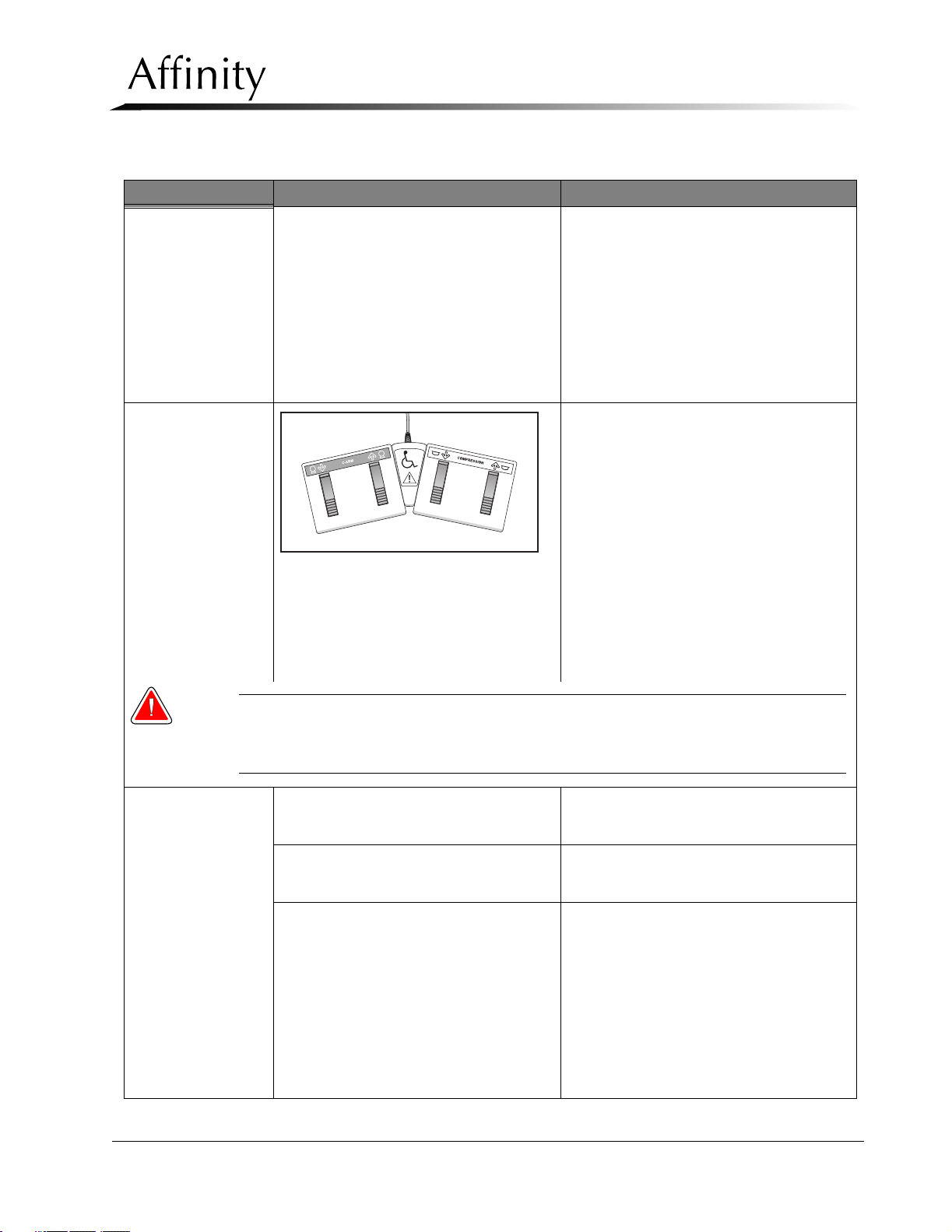
Service Manual
Chapter 3: Functional Checks/Setting Defaults
Table 3-1: Post Power-Up Checks
Functional Check Button Procedure
C-Arm Controls—
(continued)
Footswitch Controls
7. C-arm Rotation Release (Figure 3-2, Item
4)
A. Verify C-arm can be rotated when
button is held and that the C-arm
brake prevents rotation when button is
released.
B. Verify that when the C-arm rotates, the
rotation readouts on the Gantry
change accordingly. Verify the angle
display shows zero degrees of rotation
when the C-arm is in the “CC”
position.
A. The footswitch controls provide a pair
of pedals that control C-arm and
compression movement while freeing
the operator’s hands during
positioning.
System Power Up
B. The movements provided by these
pedals (C-arm Up, C-arm Down,
Compression Up, and Compression
Figure 3-3: Dual Function Footswitch
Down) are identical to that of the
corresponding controls on the C-arm
keypads.
C. Verify footswitch functionality as per
the C-arm Controls Procedures, Steps
2, 4, 5, and 6.
Warning:Upon completion of footswitch functional check, ensure the footswitch is
positioned in such a way as to prevent accidental activation by patients or
operators.
Tubehead Controls
1. C-arm Up (Figure 3-5, Item 2)
2. C-arm Down (Figure 3-5, Item 3)
3. C-arm Rotation Release (Figure 3-5,
Item 4)
A. Verify C-arm moves up while button is
held and stops when button is
released.
A. Verify C-arm moves down while
button is held and stops when button
is released.
A. Verify C-arm can be rotated when
button is held and that the C-arm
brake prevents rotation when button is
released.
B. Verify that when the C-arm rotates, the
rotation readouts on the Gantry
change accordingly. Verify the angle
display shows zero degrees of rotation
when the C-arm is in the “CC”
position.
P/N 9-500-0255 3-5
Page 48
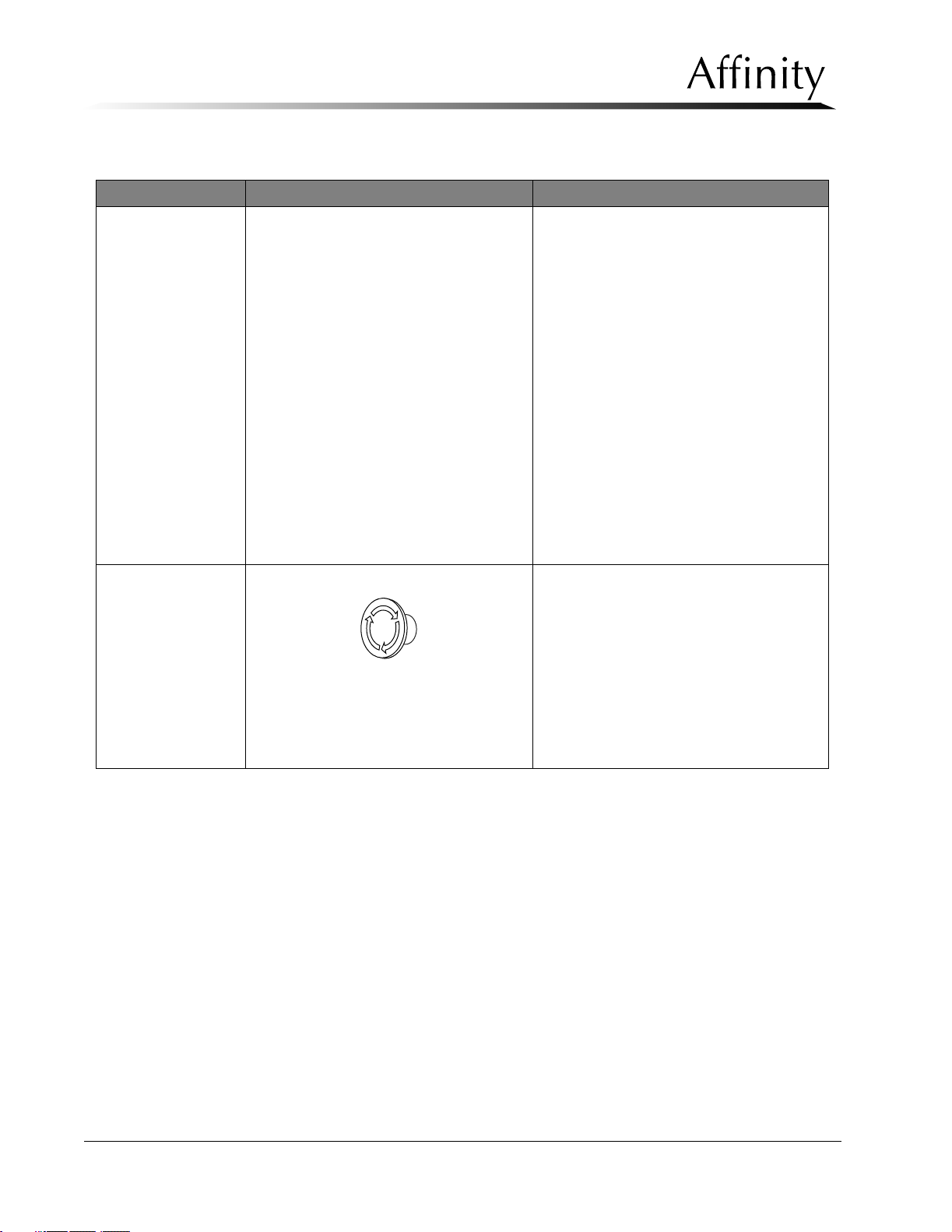
Service Manual
Chapter 3: Functional Checks/Setting Defaults
System Power Up
Table 3-1: Post Power-Up Checks
Functional Check Button Procedure
Filter Changer
Emergency OFF
Switches
1. No button, software selectable
Figure 3-4: Emergency OFF
A. Select the Mo filter via the Run Mode
Screen on the Control Panel. Refer to
the Affinity Series Operator’s Manual
for detailed information on selecting
filters.
B. Verify that the Mo LED (Figure 3-2,
Item 8) lights on each 7-button Switch
Pad.
C. Ensure the Run Mode’s Filter data line
indicates Mo.
D. Select the Rh filter via the Run Mode
Screen on the Control Panel.
E. Verify that the Rh LED (Figure 3-2,
Item 8) lights on each of the 7-button
Switch Pads.
F. Ensure the Run Mode’s Filter data line
indicates Rh.
A. Press any of the three EMO switches
on the Gantry. Verify power is
immediately removed.
B. To reset, turn the EMO switch one-
quarter turn, then place the circuit
breaker to the ON position.
C. Repeat for the remaining Gantry EMO
switches and for the switch located on
the remote control panel mounting
block (if installed).
3-6 P/N 9-500-0255
Page 49
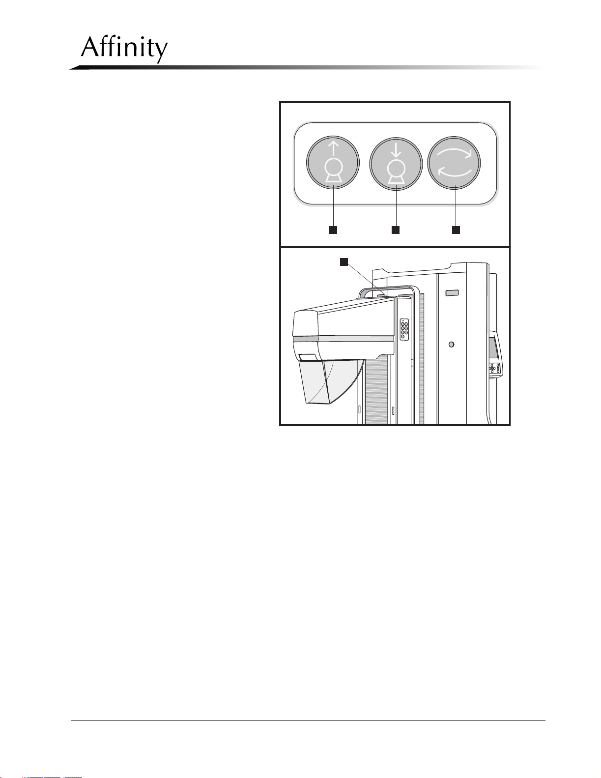
Legend for Figure 3-5
1. Tubehead Controls (location)
2. C-Arm Up Switch
3. C-Arm Down Switch
4. C-Arm Rotation Release
Switch
Service Manual
Chapter 3: Functional Checks/Setting Defaults
System Power Up
2
1
3
Figure 3-5: The Tubehead Controls
4
P/N 9-500-0255 3-7
Page 50
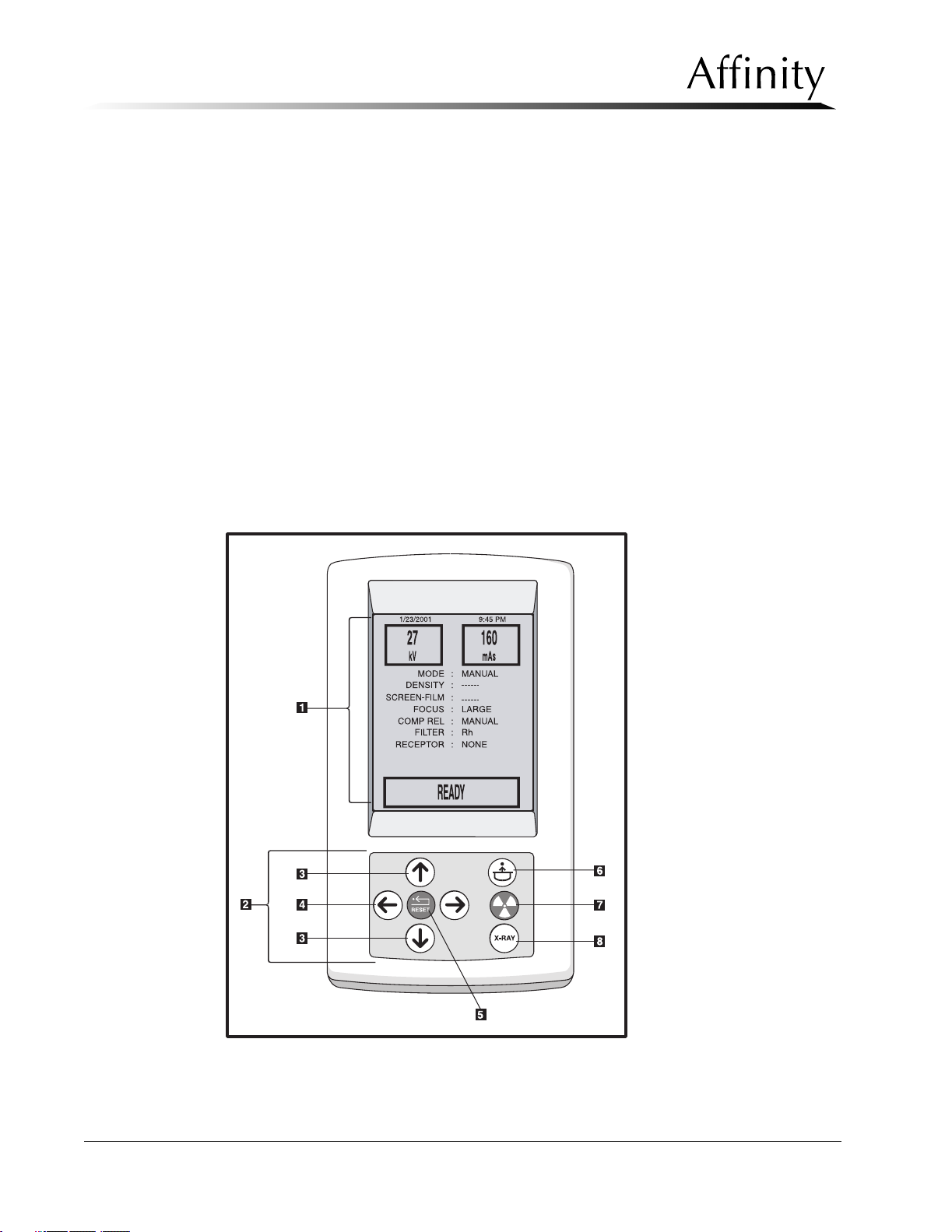
Service Manual
Chapter 3: Functional Checks/Setting Defaults
The Affinity Series Control Panel
3.0 The Affinity Series Control Panel
The Affinity Series Control Panel (Figure 3-6) is the user interface which provides the operator
with the ability to set exposure parameters and change system settings. The Control Panel is
equipped with the following:
1. Display Screen - Displays the current exposure techniques and system settings.
2. Function Keypad - Contains the following controls/keys:
3. Scroll Keys - Up/Down arrow keys used to move the on-screen highlight (cursor).
4. Change Keys - Left/Right arrow keys used to select options on highlighted field.
5. Reset Key - Used to acknowledge and clear an alert message. When used with Change
keys, it allows user to change screens. When used with Scroll keys, it adjusts the contrast
of the Control panel LCD display.
6. Compression Release Key - Used to release the compression brake and raise the
compression device approximately 10 cm.
7. Exposure Indicator - Illuminates when the system is generating x-rays.
8. X-ray Exposure Key - Used to initiate an exposure.
Legend for Figure 3-6
Figure 3-6: The Affinity Series Control Panel
3-8 P/N 9-500-0255
Page 51
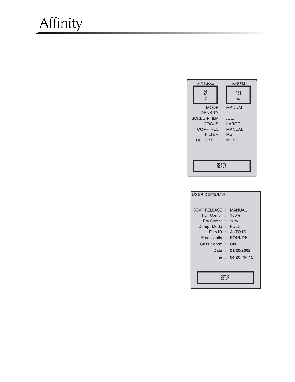
3.1 Control Panel Screens
The Affinity Series Control Panel displays three user mode screens, one debug screen and
three calibration screens. Pressing the Reset + Right Arrow or Reset + Left Arrow keys will
move to the next or previous screen. The screens are briefly described as follows:
The Run Mode Screen (Figure 3-7) is
displayed after power up. The data
fields allow the operator to select
exposure techniques, receive messages regarding system status, make
x-ray exposures, initiate compression
release and select filter. The screen
also offers a field to choose the compression release method.
Service Manual
Chapter 3: Functional Checks/Setting Defaults
The Affinity Series Control Panel
The User Default Screen (Figure 3-8)
allows the user to set the defaults for
compression release, compression
force, cassette sense, film ID, force
units, date, and time. The choices
made in the User Default Screen will
be displayed after power up.
Figure 3-7: The Run Mode Screen
Figure 3-8: The User Default Screen
P/N 9-500-0255 3-9
Page 52
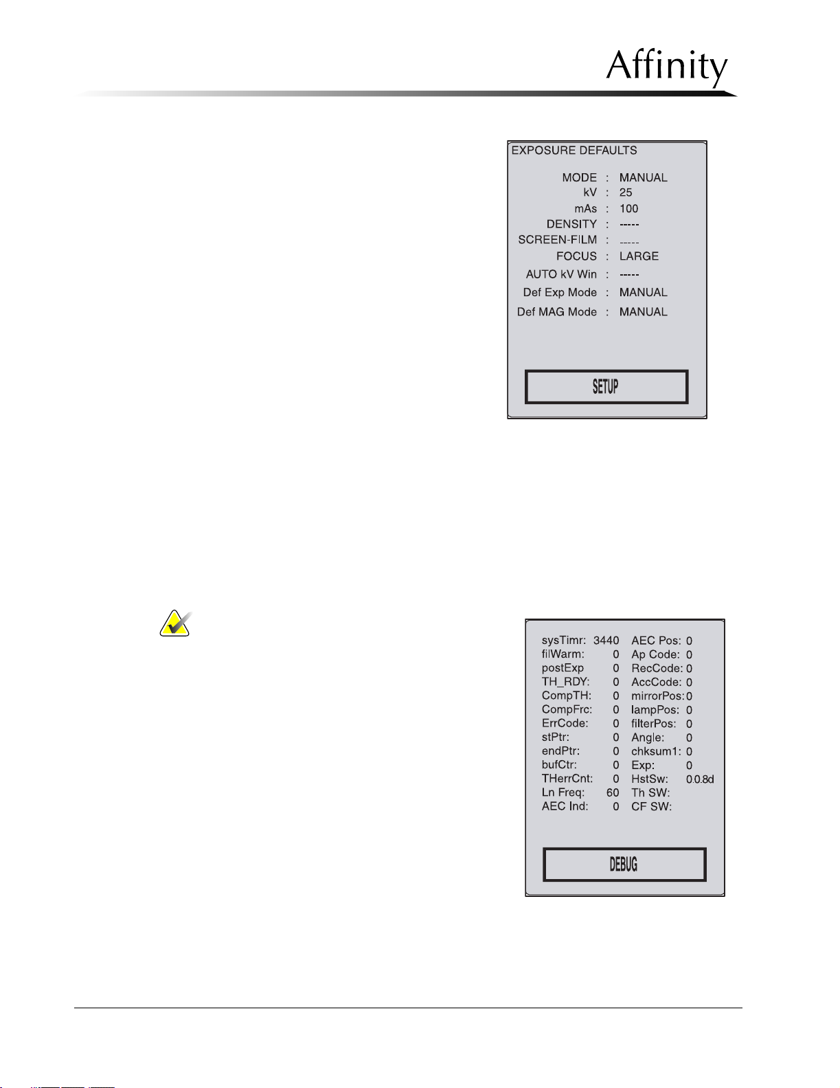
Service Manual
Chapter 3: Functional Checks/Setting Defaults
The Affinity Series Control Panel
Exposure Default Screen (Figure 3-9)
allows the user to set system defaults
for exposure techniques. The choices
made in the Exposure Default Screen
will be reflected in the Run Mode
Exposure settings displayed after
power up.
Figure 3-9: The Exposure Default
Screen
Press Reset + Right Arrow together to select the User Default Screen from the Run Mode
Screen. To select the Exposure Default Screen from the Run Mode Screen, press Reset +
Right Arrow twice. To go back to the Run Mode Screen from the Exposure Default Screen,
press Reset + Left Arrow twice, from the User Default Screen, press Reset + Left Arrow once.
Note… Access to the Calibration Mode (the
Debug Screen and the three
Calibration Screens) will require the
servicing engineer to configure a
DIP switch on the Microprocessor
Board (see Chapter 4, Section 2.1,
Entering Calibration Mode).
The Calibration Mode/Debug Screen
(Figure 3-10) displays serial communications information throughout the unit.
Figure 3-10: The Calibration Mode/
Debug Screen
3-10 P/N 9-500-0255
Page 53
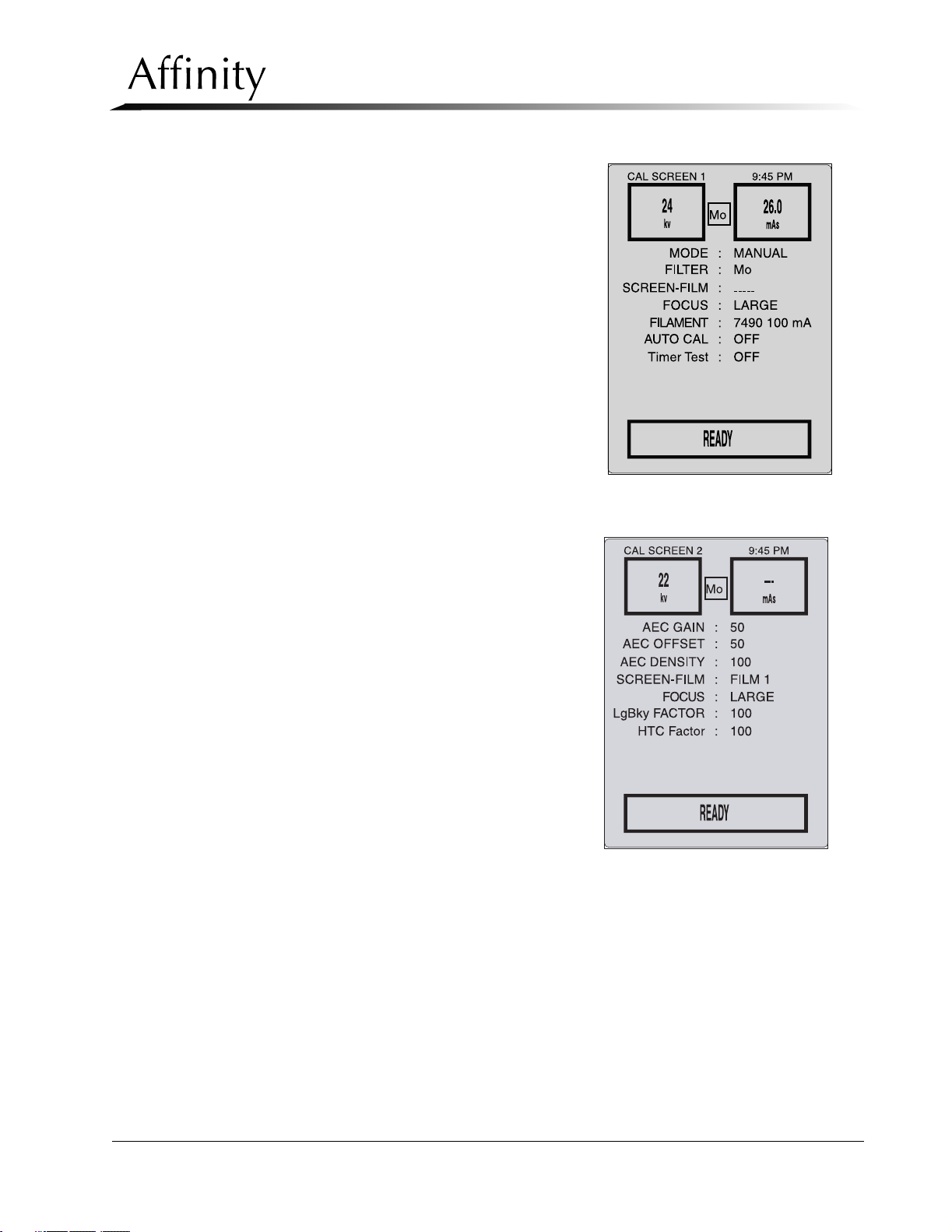
Chapter 3: Functional Checks/Setting Defaults
Calibration Screen #1 (Figure 3-11)
allows changes to system calibration
values such as Filament Current
Service Manual
The Affinity Series Control Panel
Figure 3-11: Calibration Screen #1—
Calibration Mode
Calibration Screen #2 (Figure 3-12) is
accessed when setting up and calibrating the automatic exposure control system, including the AEC Gain,
AEC Offset, and AEC Density. When
Cal Screen #2 is selected, the
machine is fixed in Auto-Time Mode.
Figure 3-12: Calibration Screen #2—
Calibration Mode
P/N 9-500-0255 3-11
Page 54
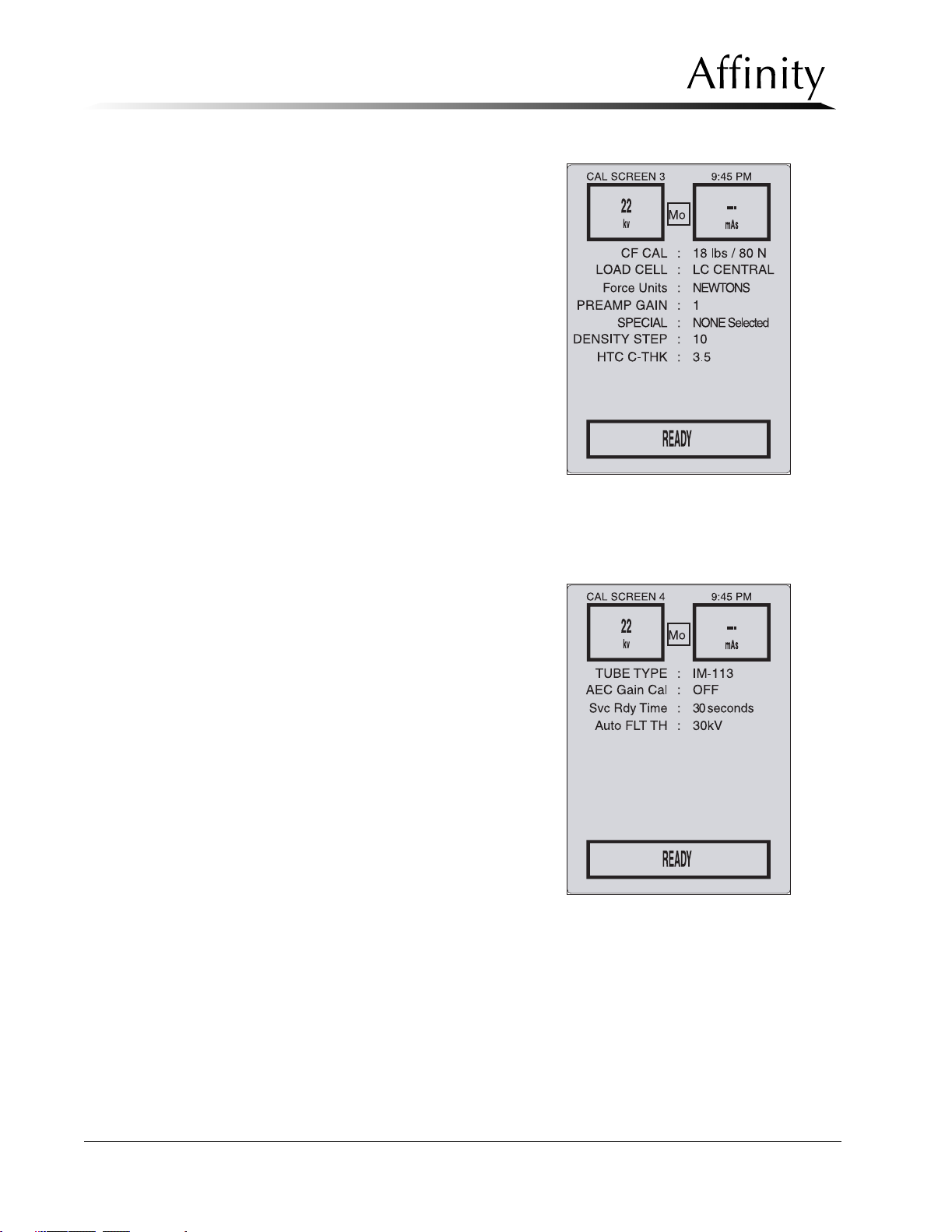
Service Manual
Chapter 3: Functional Checks/Setting Defaults
The Affinity Series Control Panel
Calibration Screen #3 (Figure 3-13)
is accessed to calibrate electromechanical systems and to perform
the backup timer test. When setting
CF CAL and SPECIAL commands,
pressing Reset + Comp Rel will
send the selected command.
Figure 3-13: Calibration Screen #3—
Calibration Mode
Calibration Screen #4 (Figure 3-14)
is accessed to set the x-ray tube
type, perform AEC Gain Calibration, set the wait time between
exposures when in service mode,
and to set the Auto Filter Threshold.
Figure 3-14: Calibration Screen #4—
Calibration Mode
3-12 P/N 9-500-0255
Page 55
4.0 Setting User Defaults
The machine parameters listed below, are set up via the User Default Screen (Figure 3-8)
using the Scroll and Change keys. For detailed instructions on setting these defaults, refer to
the Affinity Operator’s Manual.
• Compression Release—Manual or Automatic.
• Manual—Requires the user to press a Compression Release button after each expo-
sure.
• Automatic—Sets the unit so the compression device will immediately lift after an
exposure.
Note… When a localization paddle is installed, the system automatically disables
the motorized compression release function.
• Full Compression—10% to 100% selectable (25 to 40 lb compression)
• Pre Compression—10% to 100% selectable (15 to 30 lb compression)
• Compression Mode—Full Compression or Pre Compression
• Film ID—None, Printer, Auto ID, Rapid ID
• Force Units—Newtons or Pounds
• Cassette Sense—Prevents x-rays from being taken if the Bucky is not loaded, or if the
cassette is not ejected from the Bucky after it is exposed. Select ON or OFF.
Service Manual
Chapter 3: Functional Checks/Setting Defaults
Setting User Defaults
Note… When the Cassette Sense is set to ON, the system will remain in Standby
until a new cassette is installed.
• Date—US format or International format
• Time—12 hour format or 24 hour format
5.0 Setting Exposure Technique Defaults
The exposure techniques listed below, are set up via the Exposure Default Screen (Figure 3-9)
using the Scroll and Change keys. For detailed operating instructions on setting these
defaults, refer to the Affinity Operator’s Manual.
• Mode—Allows you to set the exposure mode the unit defaults to upon power up.
The available choices are:
• Manual
• Auto-Time
• AUTO-kV
• Auto-Filter
• Mag Manual (applicable only when a magnification device is installed)
• Mag Auto-Time (applicable only when a magnification device is installed)
• Mag Auto-kV (applicable only when a magnification device is installed)
• kV—20 to 39 kV, dependent on filter selected
Note… At kVs above 32, maximum mAs is restricted to less than 500 mAs for large
focal spot and 150 mAs for small focal spot.
P/N 9-500-0255 3-13
Page 56

Service Manual
Chapter 3: Functional Checks/Setting Defaults
Setting Exposure Technique Defaults
• mAs—Large FS, 3 to 500 mAs; Small FS, 3 to 150 mAs; manual exposures
require that the user set a fixed mAs for exposure timing.
• Density—+5 to Normal to -5 (not available in Manual or Mag Manual modes)
• Screen Film—Film 1, Film 2, Film 3
• Focus—Large or Small Focal Spot
• Auto-kV Window—When the exposure mode is set to Auto-kV or Auto-Filter the
system determines the exposure factors necessary to make films at the optimum
optical density, with ideal contrast. To do this, the user must set a timing “win-
dow” that determines when to terminate the exposure. The timing window
choices for Large FS are 125, 165, or 200 mAs and the choices for Small FS are
38, 50, or 60 mAs. The Auto timing window (based on breast thickness) should
be selected by those users who are required to meet the 2 mGy (200 mrad) maximum average glandular dose requirement.
• Default Exposure Mode—Displays default mode that unit is set to upon power
up.
• Default Mag Mode—Displays default mode when a magnification device is
installed.
• Filter—Upon start up, Filter is always set to Molybdenum, user can change setting to Rhodium.
3-14 P/N 9-500-0255
Page 57
Service Manual
Chapter 4: Calibrations and Performance Checks
Chapter 4: Calibrations and Performance Checks
1.0 Introduction
This chapter contains the Affinity Series calibration, adjustment, and performance and
compliance check procedures. The procedures described in the following sections are as
follows:
Introduction
Caution:
• Calibration Procedures (Section 2.0)
• Performance Check Procedures (Section 6.0)
• X-ray and Light Field Check and Alignment (Section 7.0)
• Mechanical Adjustments (Section 8.0)
Attention:
Always observe Electrostatic Discharge (ESD) precautions when working
with electronics and electronic components.
X-Ray exposures taken in rapid succession may exceed the thermal
capacity of the system. During periods of numerous x-ray exposures, such
as during service calibration or physicist accreditation, please wait a
minimum of 40 seconds between exposures to allow adequate cooling of
the x-ray tube and high voltage electronics.
2.0 Calibration Procedures
Use the following procedures to setup, check, and calibrate the mammography unit’s
exposure generating system, the automatic exposure control system, C-arm Safety
microprocessor board, and the compression control system. On initial installation, always
perform the procedures in this section in the order that they are presented to ensure proper
setup and calibration.
To download Calibration Data to a Laptop Computer, refer to Chapter 5, Section 3.3.
Warning: Service engineers must take appropriate radiation safety measures
when testing (or maintaining) the unit.
Note… When servicing the Affinity, if a procedure instructs you to remove the
Gantry right-side cover or the tubehead covers, do not replace these covers
until all required procedures (e.g., calibrations, adjustments, tests, remove
and replace, etc.) are completed.
P/N 9-500-0255 4-1
Page 58
Service Manual
Chapter 4: Calibrations and Performance Checks
Calibration Procedures
2.1 Entering Calibration Mode
The Affinity Series has four calibration screens which are used to setup and calibrate the xray generating system, the automatic exposure control system, and the electro-mechanical
sub-systems (compression force, thickness, etc.).
Perform the following to access the Calibration Mode screens:
1. Turn the unit off.
2. To access the Host Microprocessor Board (Figure 6-1, Item 7), remove the Gantry rightside panel as per Chapter 6, Section 2.1.1.
3. Locate DIP switch (S2) at the lower right side of the Microprocessor Board. Set the unit
for the Service Mode (S2 switch 1 = ON). Table 4-1 shows all the switch settings and
their functions.
4. Turn power ON. When the Run Mode appears, the unit is in the Service Mode.
5. The three user screens (Run Mode, User Default, and Exposure Default), the Debug
screen, and the three calibration screens (Cal #1, Cal #2, Cal #3, and Cal #4) are now
accessible by pressing Reset + Left Arrow or Reset + Right Arrow.
Table 4-1: Microprocessor S2 DIP Switches
Switch Function (0=OFF/1=ON)
1ON
OFF —User Mode/20 sec standby
2ON
OFF —Normal Operations
3ON—Disables X-ray Footswitch
OFF —Enables X-ray Footswitch (Normal Operations)
4ON—Enables display of actual mAs in manual mode.
OFF —Normal Operations
5
6-8 --- Reserved for language (future use)
ON
OFF
—Service Mode/post exposure standby, 30, 45, or 60 sec
selectable in Cal Screen #4
—Disables CF and tubehead communication when not
part of system
—Enables Adaptive Filament Function
—Disables Adaptive Filament Function
4-2 P/N 9-500-0255
Page 59
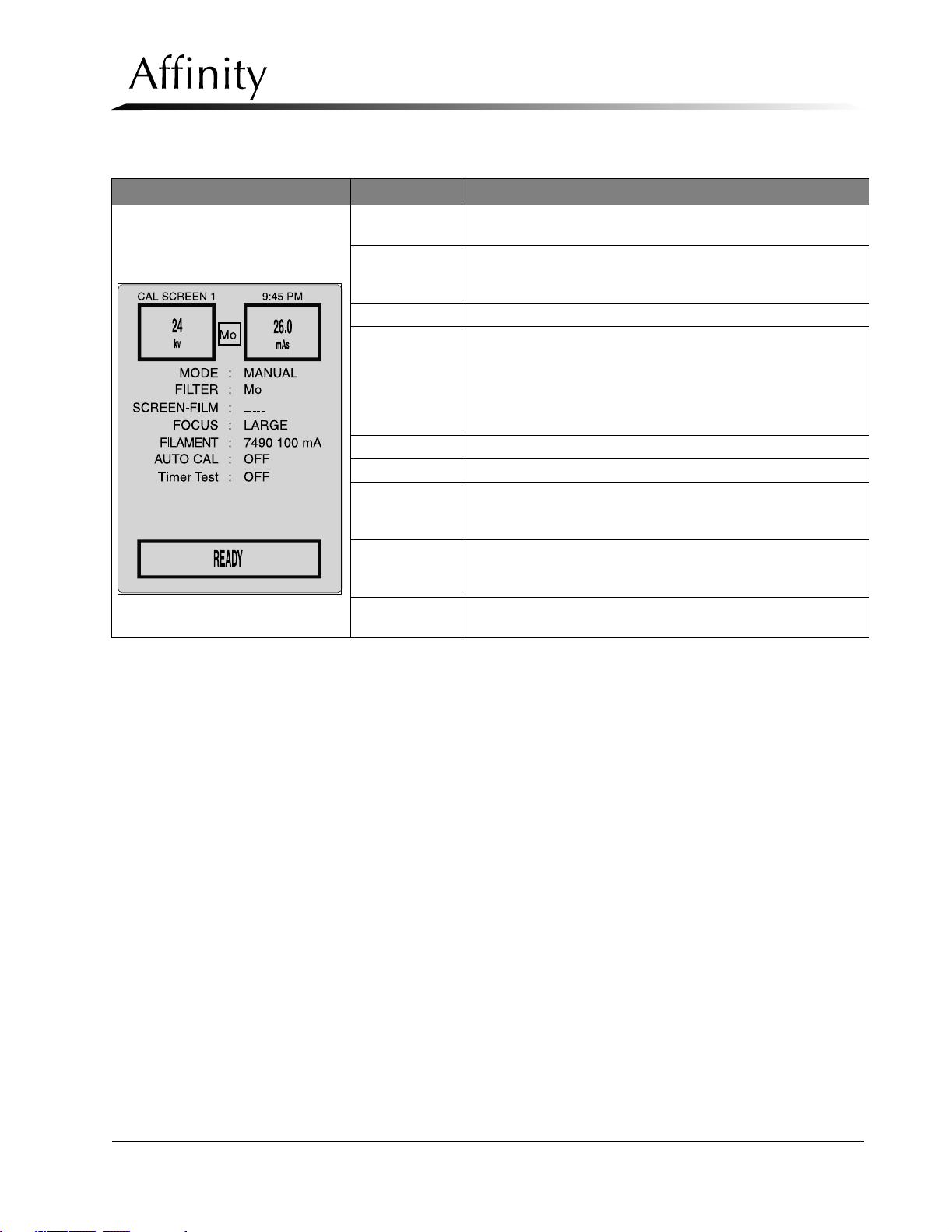
Chapter 4: Calibrations and Performance Checks
The data fields for each calibration screen are described in Table 4-2.
Table 4-2: The Calibration Screens
Calibration Screen Field Comments
Service Manual
Calibration Procedures
Calibration Screen #1
(Filament Screen)
kV
mAs
FILTER Mo/Rh
MODE
SCREEN-FILM User selects film type (Film 1, 2, or 3)
FOCUS User selects Large or Small Focal Spot Size
FILAMENT
AUTO CAL
Timer Test
Shows selected kV or displays post-exposure kV in Auto-kV or
Auto-Filter modes
Shows selected mAs or displays post-exposure mAs in Manual
and Auto Modes. Maximum selectable mAs is dependent upon
kV and Focal Spot.
Manual: User selects kV, mAs and Focal Spot Size.
Auto-Time: User selects kV, Screen-Film, and Focal Spot Size.
Auto-kV: System automatically selects kV and mAs. User selects
Screen-Film and Focal Spot Size.
Auto-Filter: Provides full automatic operation of all technique
factors. User selects Screen-Film.
On systems with HTC Buckys, used when performing reduced
mA calibration portion of Filament Current (mA) Calibration
Procedures (Section 4.3).
When set to ON during Filament Current (mA) Calibration
Procedures (Section 4.3) the system will automatically adjust the
starting filament values.
Used in Backup Timer Test (Section 4.4) to verify Backup Timer
is working properly.
P/N 9-500-0255 4-3
Page 60
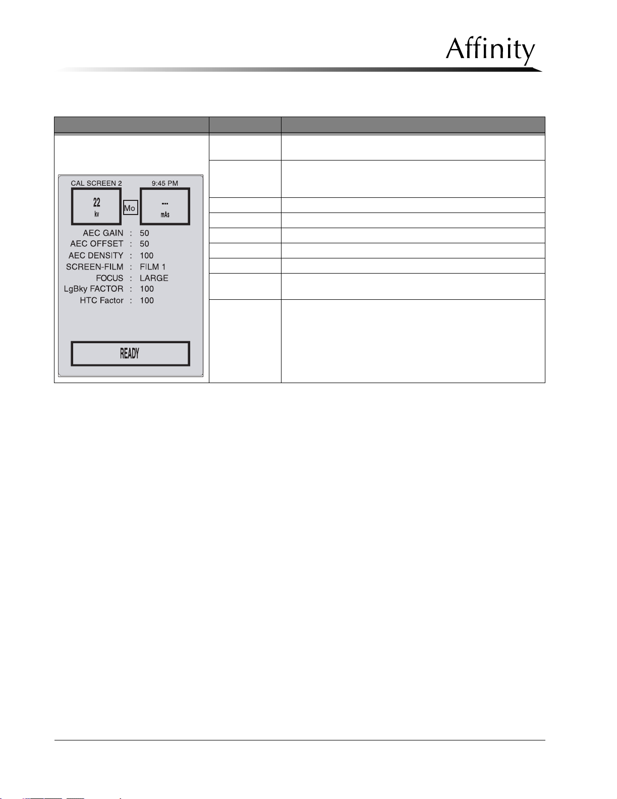
Service Manual
Chapter 4: Calibrations and Performance Checks
Calibration Procedures
Table 4-2: The Calibration Screens
Calibration Screen Field Comments
Calibration Screen #2
(AEC Screen)
kV
mAs
AEC GAIN Used during AEC Calibration (Section 5.0)
AEC OFFSET Used during AEC Calibration (Section 5.0)
M-DENSITY Used during AEC Calibration (Section 5.0)
SCREEN-FILM User selects film type (Film 1, 2, or 3)
FOCUS User selects Large or Small Focal Spot Size
LgBcky
FACTOR
HTCFactor UsedduringAECCalibration(Section5.0)
Shows selected kV or displays post-exposure kV in Auto-Time
mode.
Shows selected mAs or displays post-exposure mAs in AutoTime Mode. Maximum selectable mAs is dependent upon kV
and Focal Spot.
Used during AEC Calibration (Section 5.0)
4-4 P/N 9-500-0255
Page 61
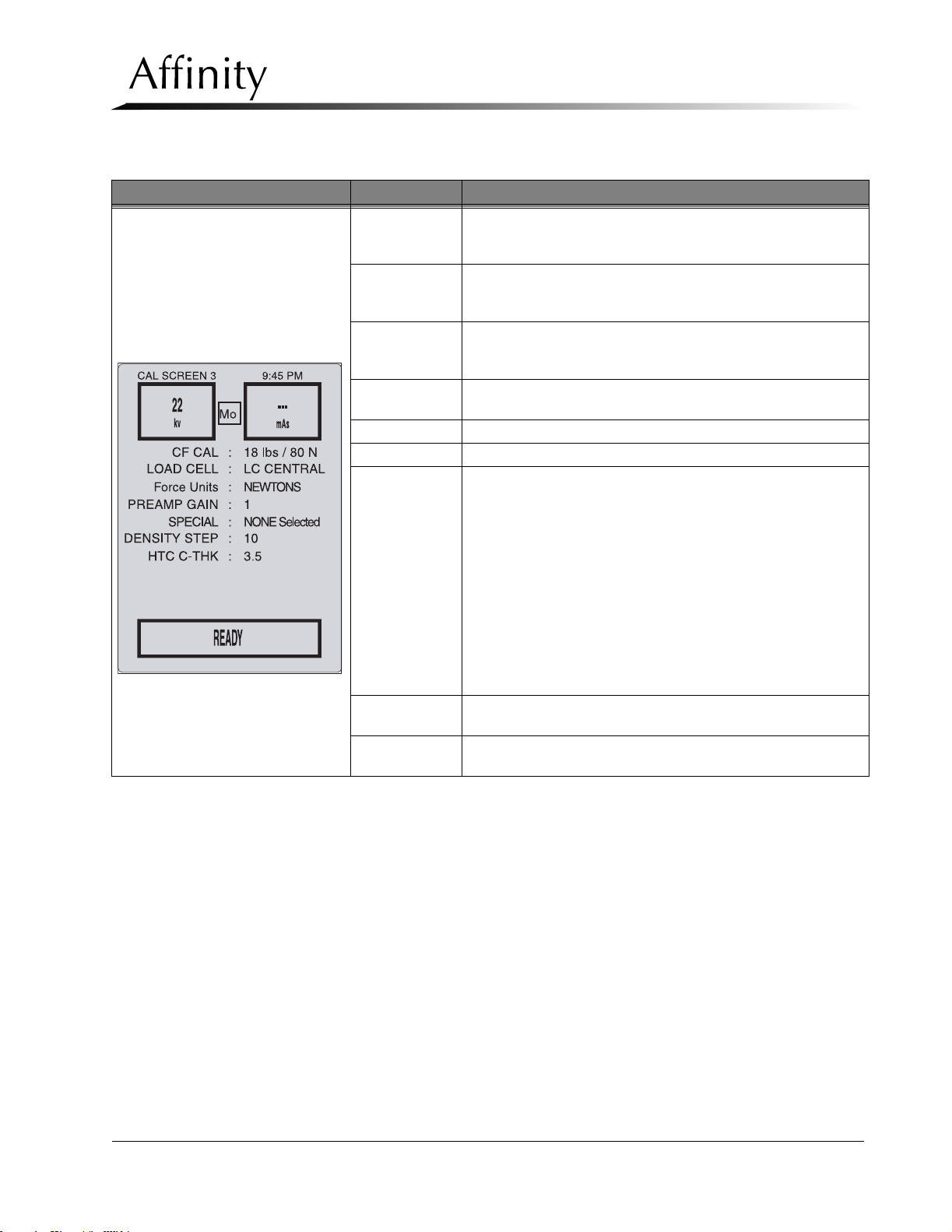
Chapter 4: Calibrations and Performance Checks
Table 4-2: The Calibration Screens
Calibration Screen Field Comments
Shows selected kV or displays post-exposure kV in Auto-kV or
kV
mAs
Calibration Screen #3
(C-arm Screen)
CF CAL
LOAD CELL
Force Units Allows user to select NEWTONS or POUNDS
PREAMP GAIN Factory set to 1, not adjustable.
SPECIAL
DENSITY STEP
HTC THK
Auto-Filter modes. Also used for kV Control Offset Calibration
(refer to Section 9.1)
Shows selected mAs or displays post-exposure mAs in Auto
Modes. Maximum selectable mAs is dependent upon kV and
Focal Spot.
Used when calibrating the compression force sensing circuits for
accurate force display (refer to Section 3.1). Available selections
are 18 lb/80 N, 34 lb/151 N, Thickness,andVerify.
Allows user to select type of Load Cell, REVERE or LC
CENTRAL
Allows user to select additional service functions:
NONE SELECTED: No special functions selected.
INIT CAL DATA: Used to initialize Calibration data on the Host
Microprocessor board (refer to Chapter 6, Section 2.3.1,Display
Microprocessor Board, p. 6-9)
CLEAR EXP CNT: Resets the Exposure Counter (refer to
Chapter 6, Section 3.2.2.1,Exposure Counter Reset, p. 6-37)
DOWNLOAD CAL: Used to download calibration data to a
laptop computer (refer to Chapter 5, Section 3.3,System Data
Retrieval, p. 5-10).
VIEW ERROR LOG: Used to view and/or download the Alert
Codes Log to a laptop computer (refer to Chapter 5, Section
3.3,System Data Retrieval, p. 5-10).
Sets Density Step value of 6, 8, 10, or 12.5%. Factory default to
10%.
Used for calibration HTC Factor (Offset) (refer to Section 5.16).
Factory default to 3.5.
Service Manual
Calibration Procedures
P/N 9-500-0255 4-5
Page 62
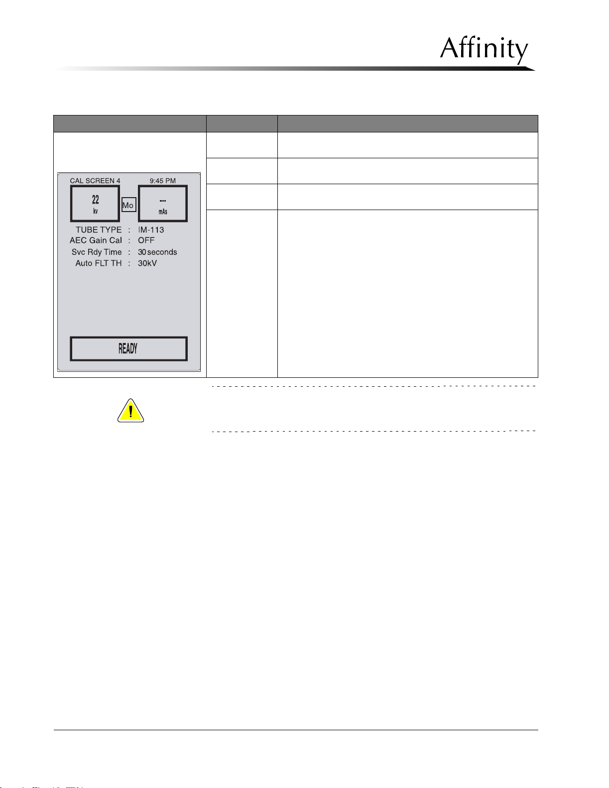
Service Manual
Chapter 4: Calibrations and Performance Checks
Calibration Procedures
Table 4-2: The Calibration Screens
Calibration Screen Field Comments
Calibration Screen #4
(Screen)
Caution:
TUBE TYPE
AEC Gain Cal
Svc Rdy Time
Auto FIL TH
Shows the type of X-ray Tube installed in the unit: IM-113.
Not selectable.
Not selectable, factory set to OFF. Used for Factory calibration of
AEC Preamp Gain.
Sets the wait time between exposures, when in service mode, to
30, 45, or 60 seconds.
Sets the Auto-Filter kV setting that determines when to switch
filters. This kV setting signals the unit to switch to the Rh filter
when the kV is equal to or greater than the chosen setting.
Always return the unit to the user mode (S2 switch 1 = OFF) after
performing calibrations to prevent inadvertent changes to system
calibrations.
4-6 P/N 9-500-0255
Page 63
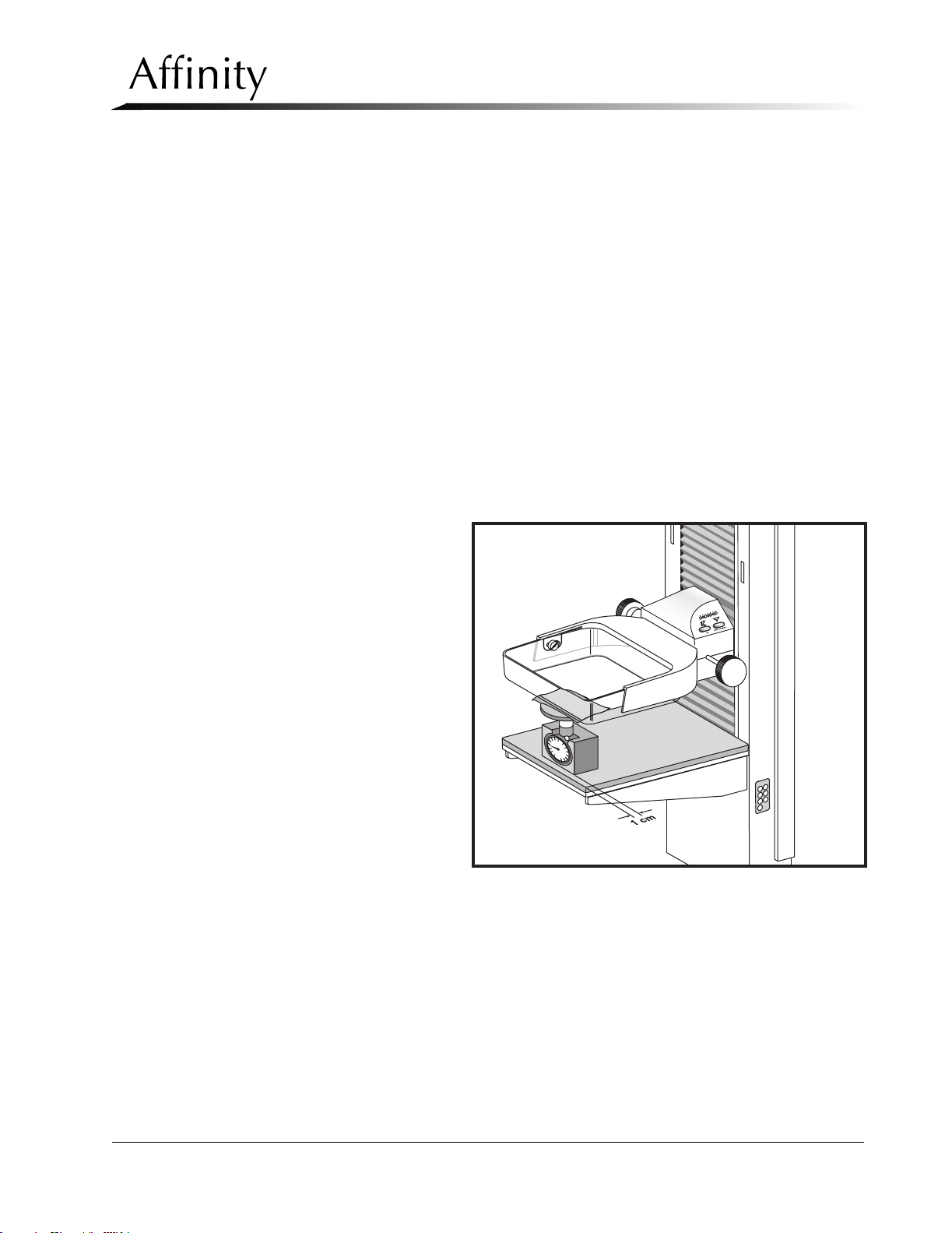
Chapter 4: Calibrations and Performance Checks
Compression System Calibration Procedures
3.0 Compression System Calibration Procedures
3.1 Compression Force Calibration
This procedure calibrates the compression force sensing circuits for accurate force display.
Be sure that the load cell selected is the type of load cell installed (refer to Table 4-2). Note
that the load cell type is factory set and should never be changed unless the load cell is
replaced.
1. Turn the unit OFF and remove the right side Gantry cover to access the Microprocessor
Board. Set the machine for the service mode (S2 switch 1 = ON).
2. Apply power. When the Run Mode appears, access Calibration Screen #3 by pressing
Reset + Left Arrow.
3. Remove any installed accessory from the Image Receptor Support Device.
4. Place a force gauge (or scale) on the IRSD. Center the scale laterally and position it 1.0
cm from chest wall edge. Install the 18 x 24 cm screening compression paddle onto the
compression device.
5. Highlight the CF Cal data field using the Scroll keys. Press a Change key until the field
reads: 80 N (18 lb).
6. Place a towel on the gauge
or scale to protect the
compression accessory
from scratches or damage.
Use motorized compression to lower the compression device until the
paddle just touches the
force gauge.
7. Use the manual compression handwheels to apply
additional compression
until the gauge or scale
indicates 18 lb of force.
Press Reset + Comp.
Release together to send
the 18 lb calibration data
to the microprocessor.
Service Manual
Figure 4-1: Compression Force Calibration Setup
8. Press a Change key until the data field reads: 151 N (34 lb). Apply additional manual
compression until the gauge or scale indicates 151 N (34 lb) of force.
9. Press Reset + Comp. Release together to send the 151 N (34 lb) calibration data to the
microprocessor.
10. Raise the compression device off of the gauge or scale, then remove the towel and
gauge. Perform the Compression Thickness calibration as per Section 3.2.
P/N 9-500-0255 4-7
Page 64
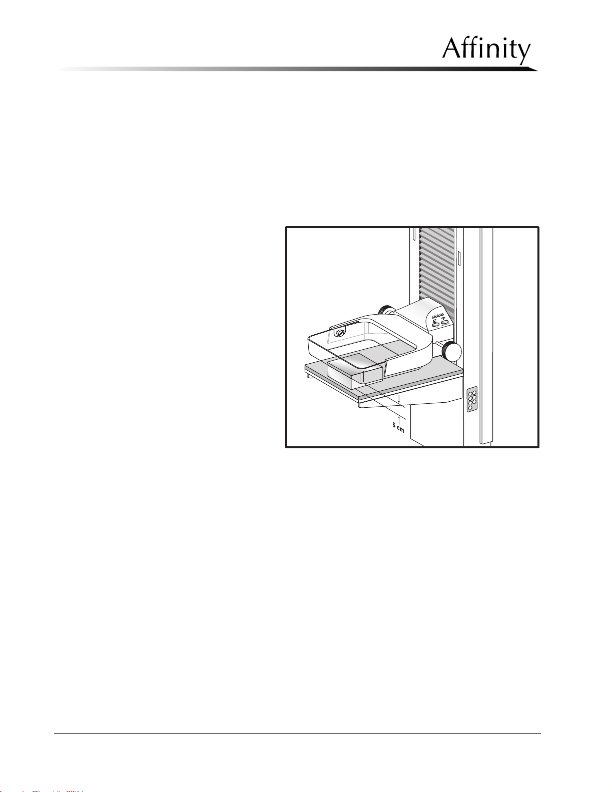
Service Manual
Chapter 4: Calibrations and Performance Checks
Compression System Calibration Procedures
3.2 Compression Thickness Calibration
This procedure calibrates the compression thickness sensing circuits for accurate thickness
display. Note that this procedure requires that the compression force be calibrated first.
Always perform the compression thickness calibration procedure with an accurately
calibrated compression force display.
1. Set the unit for the service mode (S2 switch 1 = ON). Access Calibration Screen #3 after
power up. Remove any installed accessory from the Image Receptor Support Device.
2. Highlight the CF Cal data field using the Scroll keys. Press a Change key until the field
reads: “Thickness”.
3. Place 5.0 cm of acrylic on
the image receptor support
device. Install the 18 x 24
cm compression paddle on
the compression device.
4. Use motorized compression to lower the compression paddle until it just
touches the acrylic. Use
manual compression to
apply 133.5 N (30 lb) of
force onto the acrylic.
5. Press Reset + Comp.
Release together to send
the compression thickness
calibration data to the
microprocessor.
Figure 4-2: Compression Thickness Calibration Setup
6. Highlight the CF Cal data field using the Scroll keys. Press a Change key until the field
reads: “Verify”.
7. Press Reset + Comp. Release together to send the compression thickness calibration data
to the microprocessor.
8. Raise the compression paddle, remove the acrylic from the receptor support, then return
the unit to the user mode (S2 switch 1 = OFF).
4-8 P/N 9-500-0255
Page 65
4.0 Exposure System Calibration
This section details the procedures required to calibrate the exposure-generating system.
4.1 Tube Voltage Calibration
This procedure sets the HV Generator Assembly so that the actual kV produced matches the
kV selected/indicated. This check requires use of a high-voltage divider (10,000:1 or
1,000:1), a digital voltmeter, and an adapter cable to connect the voltage divider to the test
receptacle on the unit’s HV Generator Assembly. Refer to Figure 4-3 throughout the
following procedures.
1. Turn the unit OFF.
2. Remove the left and right side Gantry doors (refer to Chapter 6, Section 2.1.1).
3. Locate the Microprocessor Board on the right side of the Gantry and set the unit for the
Service Mode (S2 switch 1 = ON).
4. Locate the HV Generator Assembly on the left side of the Gantry. Wait approximately 6
minutes before proceeding (see WARNING below).
Service Manual
Chapter 4: Calibrations and Performance Checks
Exposure System Calibration
WARNING! To reduce the risk of hazardous electrical shock, do not
attempt service until the LEDs D2 (Inverter Rail) and D35
(Brake Rail) on the HV Inverter Board are extinguished (this
will take approximately 5 minutes). Once the LEDs are
extinguished, do not proceed until an additional 1 minute has
elapsed.
5. Using a coaxial cable (Item 1) and a BNC to banana plug splitter (Item 4), connect a Dig-
ital Multi Meter (DMM, Item 2) to the anode terminal (Item 3) of the HV divider (Item 6).
Position the meter where it can be read from behind the protective radiation shield.
6. Connect the HV divider’s ground wire (Item 8) to an unpainted metal surface on Gantry.
7. Connect one end of the HV Adapter cable (Item 10) into the voltage divider receptacle
(Item 11), and the opposite end into the HV test well (Item 12) on the HV Generator
Assembly.
8. Turn power ON to unit.
Note… Skip Step 9 when performing the Tube Voltage Calibration as part of the
initial installation procedures.
9. Perform the kV Control Offset Calibration Procedures, Section 9.1
10. From the Run Mode, set the unit for a Manual mode exposure at 30 kV, 150 mAs. Moni-
tor the voltmeter from behind the radiation shield (if equipped), then conduct the exposure.
11. The voltage reading on the voltmeter for 30 kV should be 3.0 VDC (±0.06 VDC using
10,000:1 voltage divider), or 30 VDC (±0.6 VDC using 1,000:1 voltage divider).
12. If the voltage reading is not within the specification above, adjust R41 on the HV Control
Filament Board (part of HV Generator Assembly). Turn R41 clockwise to increase kV, or
counter-clockwise to decrease kV (two turns equals approximately 1 kV).
13. Repeat Steps 9, 10, and 11 until the voltage reading at 30 kV is +
fied in Step 11.
2% of the VDC speci-
P/N 9-500-0255 4-9
Page 66
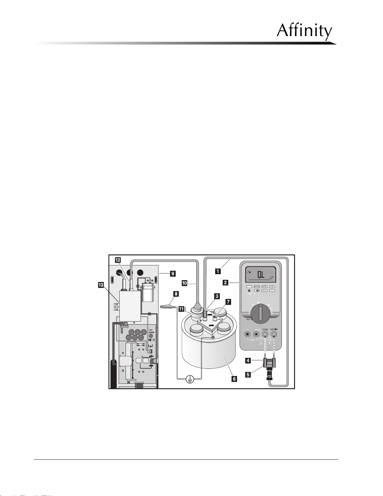
Service Manual
Chapter 4: Calibrations and Performance Checks
Exposure System Calibration
14. Set the unit for a Manual mode exposure at 39 kV, 80 mAs, Rh filter. Monitor the voltmeter from behind the radiation shield, then conduct the exposure.
15. The voltage reading on the voltmeter for 39 kV should be 3.9 VDC (±0.078 VDC using
10,000:1 voltage divider), or 39 VDC (±0.78 VDC using 1,000:1 voltage divider).
16. If the voltage reading is not within the specification above, readjust R41 on the HV Control Filament Board.
1. Coaxial Cable
2. Digital Multi Meter
3. Anode
4. BNC to Banana Plug Splitter
5. Ground side of splitter (Side of splitter with “Tab ” must be connected to Common.)
6. High Voltage Divider
7. Cathode
8. Ground wire (Attach this end of ground wire to unpainted metal surface on Gantry.)
9. Gantry
10. HV Adapter Cable
11. Voltage Divider Receptacle
12. HV Test Well
13. mA Current Jack (not shown, on left side of HV Multiplier)
Legend for Figure 4-3
Figure 4-3: High Voltage Generator Calibration Setup
17. Repeat the exposure and check the voltage reading. Repeat Steps 14, 15, and 16 until
the voltage reading at 39 kV is within the ±2% specification.
18. Check the voltage at 20 kV to verify that it remained within the ±2% specification. If
necessary continue to make adjustments at 20 kV, then at 39 kV until calibration at both
levels is achieved.
4-10 P/N 9-500-0255
Page 67
19. Select intermediate kV levels and make an exposure at each setting. Confirm that the
voltage readings on the meter are within 2% of the kV setting. If they are not, make small
adjustments at 20 kV and 39 kV to “dial” in the intermediate kV levels while maintaining
the ±2% at all kV’s.
20. For initial setup and calibration, skip this step. If all service procedures have been com-
pleted, return the unit to the user mode (S2 switch 1 = OFF), and replace all previously
removed covers and panels.
4.2 Check mA Calibration
Check the mA calibration as follows:
1. Turn the unit off. Wait approximately 6 minutes before proceeding (see WARNING
below).
WARNING! To reduce the risk of hazardous electrical shock, do not
attempt service until the LEDs D2 (Inverter Rail) and D35
(Brake Rail) on the HV Inverter Board are extinguished (this
will take approximately 5 minutes). Once the LEDs are
extinguished, do not proceed until an additional 1 minute has
elapsed.
Service Manual
Chapter 4: Calibrations and Performance Checks
Exposure System Calibration
2. On the HV Multiplier, connect a Digital Multi Meter (set to current) to the mA Current
Jack (Figure 4-3, Item 13).
3. Take an exposure at 30 kV, manual mode, 100 mAs. The meter should read 100 mA. If
not, adjust R2 on the HV Control/Filament Board.
4. Repeat Step 2 till the meter reads 100 mA.
4.3 Filament Current (mA) Calibration
This procedure sets the filament current to produce the desired mA at each kV station for the
large and small focal spots in the Affinity. This procedure also calibrates the reduced mA at
each kV station for large focal spot using an HTC Bucky.
Adaptive Filament—This function allows you to make small adjustments to the filament DAC
value when necessary each time an exposure is made. Turning switch # 5 (S2) ON enables
the function. This function is designed to keep the starting mA correct, as parameters vary
over time. It is recommended that this function is enabled.
Note… This feature is automatically disabled when Filament Current Calibration
(AUTO CAL) is ON.
Note… This calibration must be performed using Manual Exposure mode only.
1. Turn the unit OFF.
2. Remove the Gantry’s right side panel (to access the Host Microprocessor board) as per
Chapter 6, Section 2.1.1.
3. Remove the Patient Handles and the C-arm top cover to access the Filament Protection
Board as per Chapter 6, Section 3.1.2.
4. On the Microprocessor Board, set the unit for the service mode (S2 switch 1 = ON).
P/N 9-500-0255 4-11
Page 68
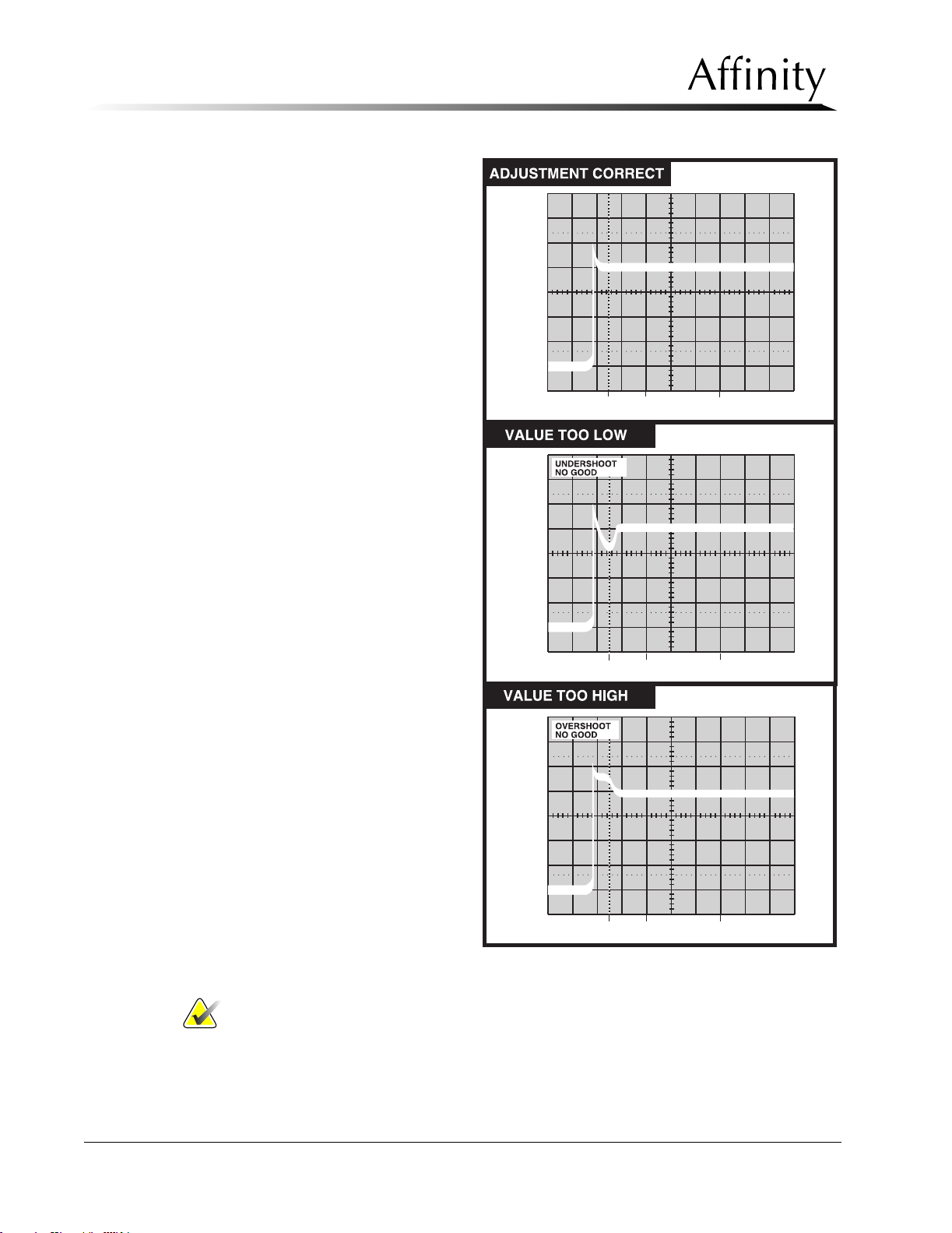
Service Manual
Chapter 4: Calibrations and Performance Checks
Exposure System Calibration
5. On the Filament Protection
Board, connect a storage oscilloscope to TP2 (mA SENSE)
and TP3 (GND).
6. Turn the unit ON.
7. Install a Bucky on the IRSD.
8. After the Run Mode screen displays, highlight the Filter data
field, and select the Mo filter.
9. From the Run Mode screen,
access Calibration Screen #1
by pressing Reset + Right
Arrow four times.
10. Highlight the Auto Cal data
field, then press a Change key
until the field reads: ON.
11. Highlight and change the
appropriate data fields to set
the unit for a Manual mode
exposure at 20 kV, 40 mAs,
Large focus.
12. Make an exposure. The system
will automatically adjust the
starting filament values. Wait
40 seconds, take a second
exposure. Wait 40 seconds,
take a third exposure. After
each exposure, check the
waveform on the oscilloscope
for under- or overshoot (Figure
4-4). Verify that the waveform
appears stable and is at the correct amplitude for the set kV as
shown in Table 4-3).
Figure 4-4: Example—Filament Waveforms Pattern
Notes… To fully calibrate the system, 3 exposures (at 40 second intervals between
shots) must be taken.
Note the mA Target (“T”) value and the mA Start (“ST”) value displayed at
the bottom of the screen. The difference between the start value and the
target value should be less than 10.
4-12 P/N 9-500-0255
Page 69

Service Manual
Chapter 4: Calibrations and Performance Checks
Exposure System Calibration
13. Repeat steps 11 and 12 for each kV station using the Large focal spot and Mo filter, then
perform this procedure for each kV station using the Small focal spot, Mo filter and 12
mAs. Record the values for each kV station on Table 4-3.
Note… Three exposures are required to properly calibrate the mA at each kV
station.
14. Go to the Run Mode Screen and switch to the Rhodium filter then repeat steps 11 and 12
for kV stations 28 kV through 39 kV for both the Large (40 mAs) and the Small (12 mAs)
focal spots. After each exposure, check the waveform on the oscilloscope for under- or
overshoot (Figure 4-4). Verify that the waveform appears stable, and is at the correct
amplitude for the set kV as shown in Table 4-3.
15. Record the values for each kV station on Table 4-3.
16. For systems with HTC Buckys, perform reduced mA calibration below. Proceed to Step
17 if the system is not equipped with HTC Buckys.
a. Go to the Run Mode Screen and switch to the Mo filter.
b. Access the Calibration Screen #1, Auto Cal data field should read ON.
c. Highlight and change the appropriate data fields to set the unit for a MAN-
UAL mode exposure at 20 kV, 12 mAs, Large focus.
d. Highlight the Filament data field and then press Reset + Compression Up
together. (This will place you in reduced mA calibration mode.)
e. Install an HTC Bucky on the IRSD.
f. Step behind the radiation shield and make an exposure. (The system will
automatically adjust the starting filament values.) Wait 40 seconds, take a
second exposure. Wait 40 seconds, take a third exposure. After each expo-
sure, check the waveform on the oscilloscope for under- or overshoot (Fig-
ure 4-4). Verify that the waveform appears stable and is at the correct
amplitude for the set kV as shown in Table 4-3. Record the reduced mA for
each station on Table 4-4.
17. Highlight the Auto Cal data field and set to OFF.
18. For initial setup and calibration, skip this step and proceed directly to Section 4.4, Step
5. If all service procedures have been completed, remove the oscilloscope probe from
the test points. Set the unit back to the user mode (S2 switch 1 = OFF), then replace previously removed covers and panels.
P/N 9-500-0255 4-13
Page 70
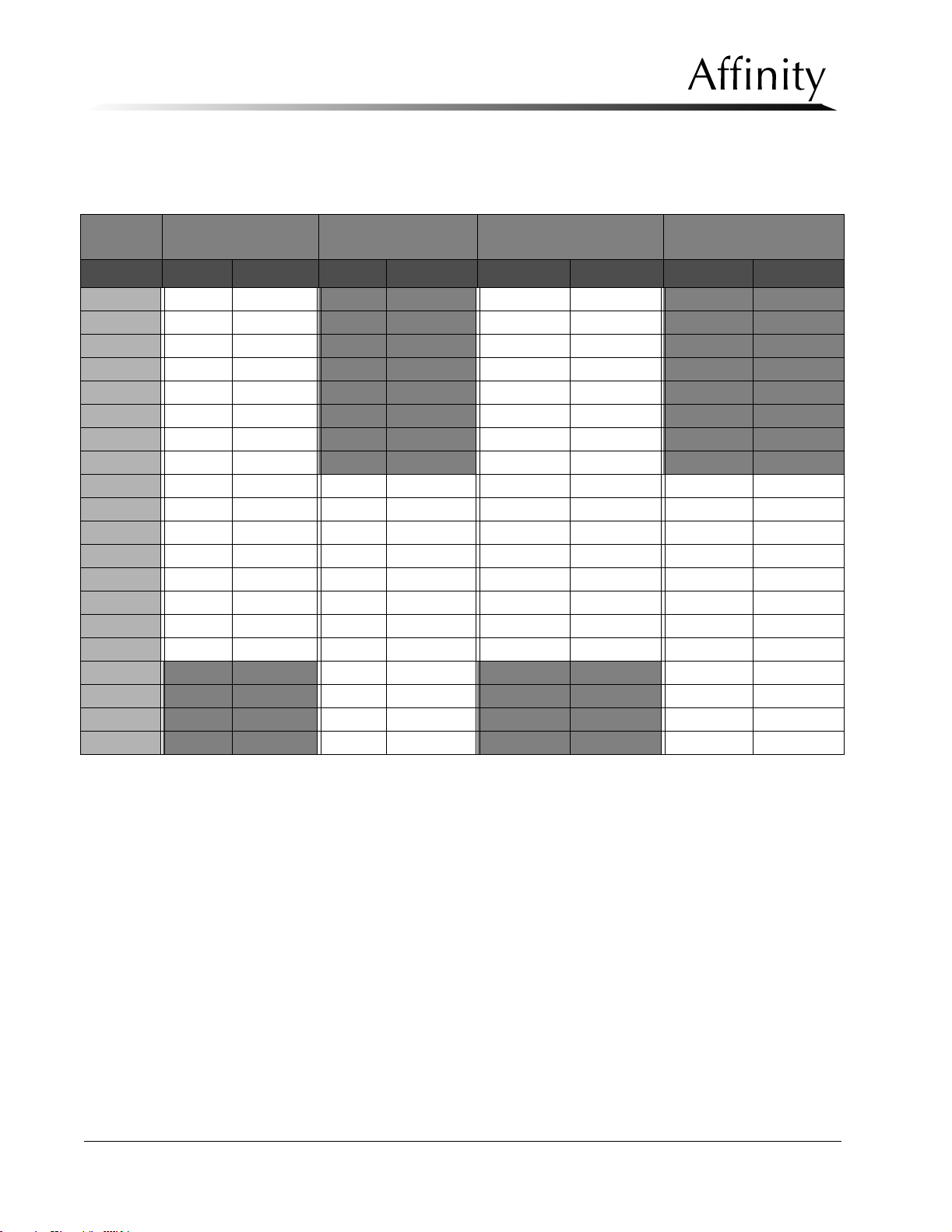
Service Manual
Chapter 4: Calibrations and Performance Checks
Exposure System Calibration
Table 4-3: Filament Waveforms Amplitude
Large Focal Spot
(Mo)
Large Focal Spot
(Rh)
Small Focal Spot (Mo) Small Focal Spot (Rh)
kV ma Results mA Results ma Results mA Results
20 kV 75 --- 20 ---
21 kV 80 --- 22 ---
22 kV 85 --- 24 ---
23 kV 90 --- 26 ---
24 kV 95 --- 28 ---
25 kV 100 --- 30 ---
26 kV 100 --- 30 ---
27 kV 100 --- 30 ---
28 kV 100 100 30 30
29 kV 100 100 30 30
30 kV 100 100 30 30
31 kV 100 100 30 30
32 kV 100 100 30 30
33 kV 85 85 28 28
34 kV 80 80 28 28
35 kV 80 80 26 26
36 kV --- 75 --- 26
37 kV --- 75 --- 26
38 kV --- 70 --- 24
39 kV --- 70 --- 24
4-14 P/N 9-500-0255
Page 71
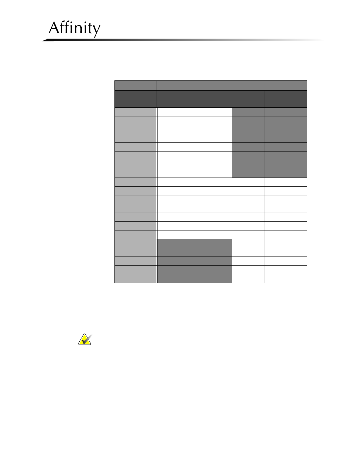
Service Manual
Chapter 4: Calibrations and Performance Checks
Exposure System Calibration
Table 4-4: Reduced mA Filament Waveform Amplitude
Large Focal Spot (Mo) Large Focal Spot (Rh)
kV Reduced
Results Reduced
ma
20 kV 20 ---
21 kV 22 ---
22 kV 24 ---
23 kV 26 ---
24 kV 28 ---
25 kV 30 ---
26 kV 30 ---
27 kV 30 ---
28 kV 30 30
29 kV 30 30
30 kV 30 30
31 kV 30 30
32 kV 30 30
33 kV 28 28
34 kV 28 28
35 kV --- 26
36 kV --- 26
37 kV --- 26
38 kV --- 24
39 kV --- 24
Results
ma
4.4 Backup Timer Test
Perform this procedure at initial installation, or after replacing the Microprocessor Board to
ensure that the Backup Timer is working properly. This test will attempt to generate a 7
second exposure. The Backup Timer must detect that the exposure duration has exceeded
the maximum and terminate the exposure immediately.
Note… This test does not generate radiation.
1. Turn the unit OFF.
2. Remove the Gantry’s right side panel (to access the Microprocessor board) as per Chap-
ter 6, Section 2.1.1.
3. On the Microprocessor board, set the unit for the service mode (S2 switch 1 = ON).
4. Turn the unit ON.
5. Access Calibration Screen #1.
6. Highlight the Timer Test data field using the Scroll keys. Press a Change key until the
data field reads: ON.
7. Turn the unit OFF.
P/N 9-500-0255 4-15
Page 72
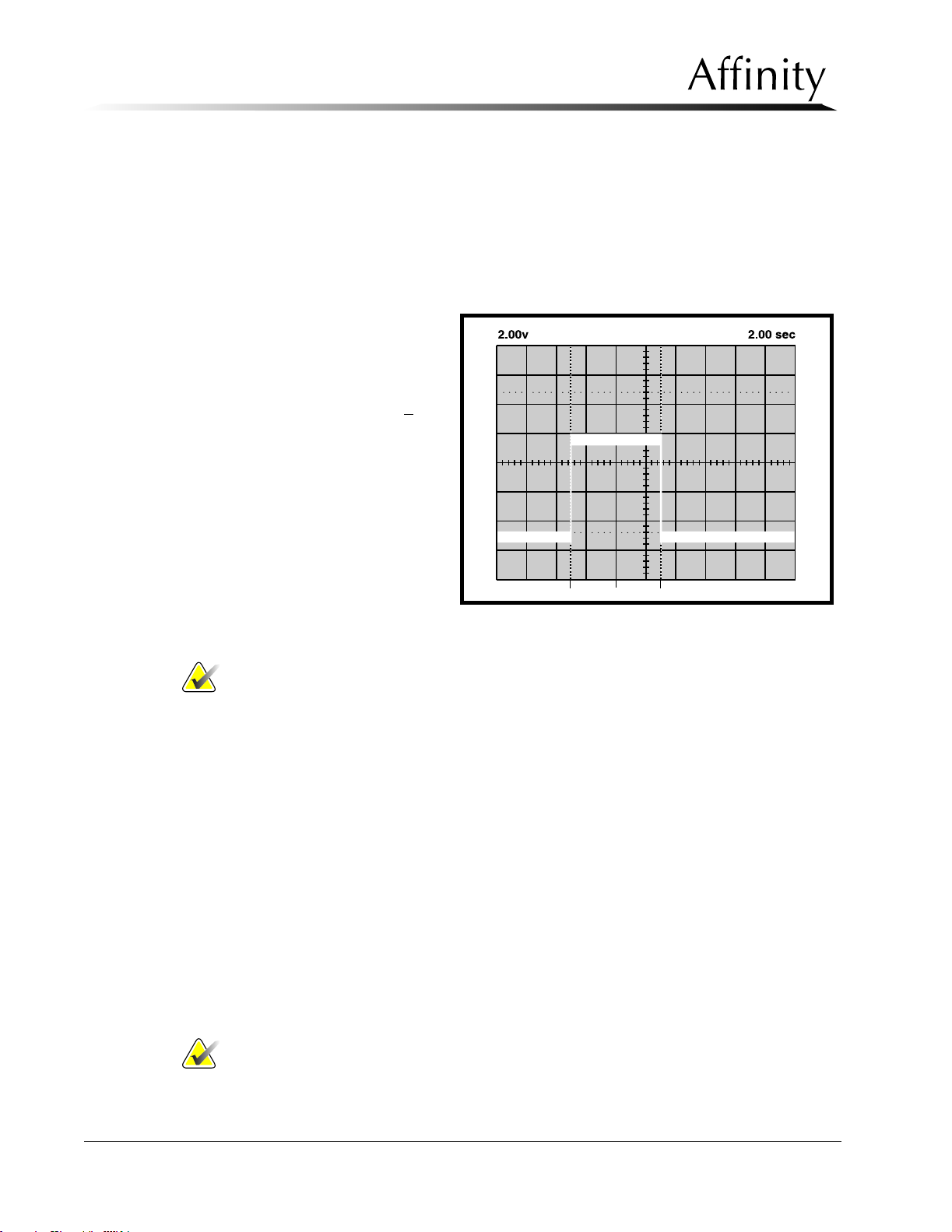
Service Manual
Chapter 4: Calibrations and Performance Checks
Automatic Exposure Control System Calibration
8. On the Microprocessor board, verify jumpers are positioned as follows (if not, install
jumpers):
• JP5 between positions 1 and 2
• JP6 between positions 1 and 2
9. Install a DIP clip on U20 and connect scope lead to Pin 2. Connect the ground lead to
TP12 (DGND).
10. Turn the Unit ON.
11. Set up scope as follows:
• Volts/DIV : 2.00 V
• Time/DIV: 2.00 sec
• Mode : AUTO
12. Set the time-out to 6.3 +
seconds as follows (refer to
Figure 4-5):
a. Trigger the IC by
momentarily shorting U11 Pin 1 to
U11 Pin 2.
b. While viewing sig-
nal on scope, adjust
Pot R146.
0.25
Figure 4-5: Example—Backup Timer Time-out Signal
Note… During the next step, the unit will not take X-rays and will attempt a 7.0 sec
exposure.
13. Initiate an exposure.
14. When the exposure terminates, the message area along the lower part of the screen indicates the exposure duration (when the timer terminated the exposure), and the status of
the test.
15. Verify that the test “PASSED”. If the indication is “FAILED”, contact L
department immediately. Do not use the system clinically.
16. The Timer Test field will automatically reset to OFF.
17. Remove all test equipment, do not remove jumpers JP5 and JP6.
18. Return the unit to the user mode (S2 switch 1 = OFF) and replace previously removed
panels.
5.0 Automatic Exposure Control System Calibration
The following sub-sections are provided to calibrate the Automatic Exposure Control (AEC)
System. Be sure the Exposure Generating System (kV & mA) is properly adjusted prior to
calibrating AEC.
Note… AEC adjustment may be required if film or film cassettes, chemistry, or
processor settings (i.e., temperature or replenishment rates) have been
changed.
ORAD Service
4-16 P/N 9-500-0255
Page 73
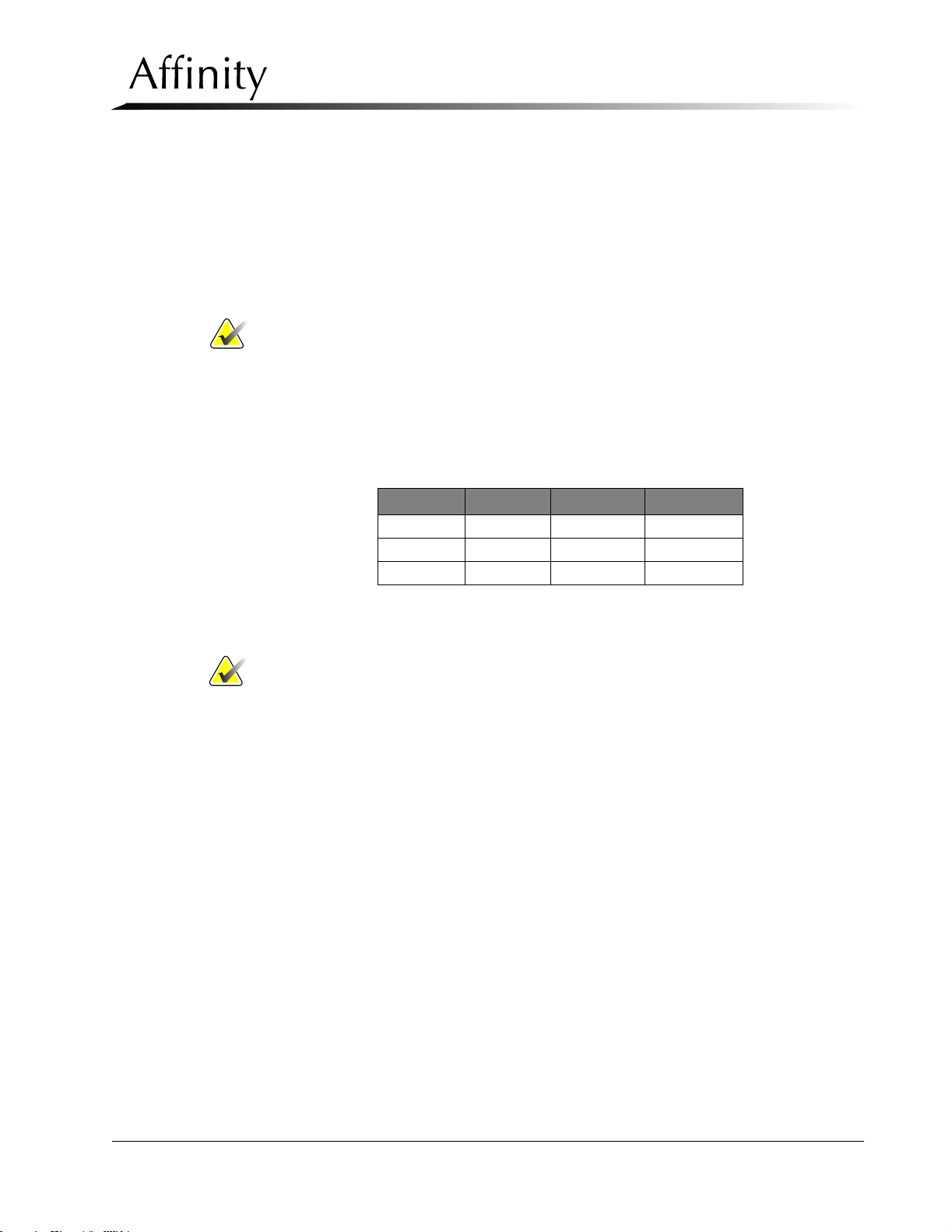
Service Manual
Chapter 4: Calibrations and Performance Checks
Automatic Exposure Control System Calibration
Calibration of the AEC is performed at the factory to assure that the system is capable of
proper calibration and performance. At installation, the AEC must be adjusted to obtain films
of the proper mean optical density (typically 1.6 OD ±0.15 OD depending on the
radiologist’s preference) using the site’s processing equipment. The HTC Factor is set to a
number determined by performing the HTC Factor (Offset) Adjustment prior to leaving the
factory. Do not change the HTC Factor prior to performing AEC Calibration as part of the
initial installation procedures. The AEC Pre-Amp Gain (shown on Calibration Screen #3) is
factory set to 1 and is not selectable or adjustable.
Note… This procedure must be performed for each film type used with the unit.
Before performing the AEC Calibration procedure, be sure to complete the
Tube Voltage Calibration and the Filament Calibration.
AEC system performance is specified at the kV’s that are normally used clinically. The
following chart presents a guideline for typical clinical values for breast composition and
thickness.
Table 4-5: Typical kV range versus compressed thickness
Thickness Fatty (kV) 50/50 (kV) Dense (kV)
2.0 cm 23-24 24-25 25-26
4.0 cm 25-26 26-27 27-28
6.0 cm 26-27 27-28 29-30
Note that 2.0 cm thickness imaging is not appropriate above 26 kV, while 6.0 cm thickness
imaging is not appropriate below 26 kV.
Notes… When calibrating the automatic exposure control system, always use the
same Bucky device and the same cassette to ensure consistent results.
For optimum calibration results use the AEC Worksheets provided at the
end of this procedure (Tables 4-6 through 4-9). Record the AEC
performance values on the worksheets when the AEC system is calibrated.
5.1 AEC Detector Gain Calibration
Any time the AEC Detector Assembly or the X-ray Tube is replaced, the following procedures
must be performed.
Required tools/test equipment:
• 2.0 cm BR-12
• Digital Volt Meter (DVM)
• Standard Issue Tool Set
1. Remove the Gantry’s right side panel (to access the Host Microprocessor board) as per
Chapter 6, Section 2.1.1.
2. Install the 18 x 24 cm Bucky onto the IRSD, insert a loaded cassette, and install a com-
pression paddle.
3. Place 2.0 cm or BR-12 on the Bucky so it covers the AEC detectors.
4. Set the unit for a Manual exposure at 30 kV, 50 mAs.
P/N 9-500-0255 4-17
Page 74

Service Manual
Chapter 4: Calibrations and Performance Checks
Automatic Exposure Control System Calibration
5. Connect an Oscilloscope 10 x 1 probe to TP33 (AEC) on the Host Microprocessor board,
connect the probe ground to TP25 (AGND). Set the oscilloscope as follows:
• Sweep Time = 10 msec per division
• Vertical Sensitivity = 2 V per division
• Trigger Mode = Normal, with positive-going edge trigger
6. Initiate an exposure and record the voltage at 25 msec after the trigger point on the oscilloscope. If the recorded voltage is between 9.2 to 9.8 VDC, the unit has passed and you
can proceed with AEC Calibration. If the unit fails, adjust the AEC Detector board resistor R1 as per Section 5.2.
5.2 AEC Detect Board—R1 Adjustment
The value of the R1 currently installed on the AEC Detect board is used to calculate the
correct value for the replacement resistor. Perform the R1 resistor value calculation as
follows:
1. Note the result of the voltage check in Step 6 of Section 5.1 above.
2. Remove the AEC Detector Assembly as per Chapter 6, Section 3.4.2.
3. Set the assembly on its side with the sensor windows on the top plate facing forward.
Remove the 6 screws securing the AEC Cover to the detector assembly.
4. Remove the cover and set aside, taking care not to touch the film covering the sensors.
5. Remove the 2 screws securing the D-sub connector to the end of the AEC Detector
Assembly. Remove connector.
6. Remove the 4 screws securing the AEC Detect board to the AEC Detector Assembly.
Remove the board.
7. Measure the resistance across R1 and calculate the replacement value using the following formula:
9.50
÷ (result noted in Step 1) x value of current R1 = replacement resistor
value
example: 9.50
÷ 11.0 VDC x 1.4 kΩ = 1.2 kΩ
Note… The replacement resistor value typically falls within the 1.0 kΩ to 1.7 k
range.
8. Replace R1 on the AEC Detect board with a 1/4 Watt, metal film, 1% resistor with the
value determined in Step 7 above.
9. Reverse Steps 2 through 6 to install the AEC Detector Assembly.
Ω
5.3 Initial Calibration—Large Focal Spot (Mo)
This procedure will make Gain and Offset adjustments to the automatic exposure control
system for large focal spot exposures. Exposures used to adjust the Offset must be taken
between 240 mAs and 350 mAs, and exposures used to adjust the Gain must be taken
between 40 and 80 mAs. Always take sample exposures, then adjust the amount of
attenuation to achieve the proper mAs before making Gain or Offset adjustments.
1. Go to Step 3 for units with no HTC Bucky, units with HTC Bucky, go to Step 2.
Note… For large focal spot calibration with an HTC Bucky, the unit must be in 100
mA mode. Ensure the HTC Threshold is low enough to remain in this mode.
4-18 P/N 9-500-0255
Page 75

Service Manual
Chapter 4: Calibrations and Performance Checks
Automatic Exposure Control System Calibration
2. Set unit to Calibration Screen #3, set the HTC C-THK threshold for 1.0 cm.
3. Set unit to Calibration Screen #2.
4. Install the 18 x 24 cm Bucky onto the IRSD and insert a loaded cassette. Always use the
same cassette and Bucky for all calibration steps.
5. Set the unit for an Auto-Time exposure at 25 kV, Large focus, Mo filter. Set the Film data
field to the screen-film combination loaded in the cassette.
6. Place 3.0 cm of BR-12 or PMMA acrylic on the Bucky, centered laterally, and extending
approximately 1.0 cm over the chest wall edge.
7. Place the AEC detector in the position closest to the chest wall. Take an exposure,
develop the film, then measure the optical density (OD).
Note… Always measure the Optical Density with the lower edge of the film flush
with the front edge of the Densitometer and centered side-to-side
(approximately 5.0 cm into film plane).
8. Make Gain adjustments to calibrate the Optical Density to the value requested by the
customer. Increase the Gain value if the density is too high. To maintain mAs requirements (40 - 80 mAs), it may be necessary to increase or decrease the amount of BR-12 or
PMMA used.
9. Make another exposure, develop the film, then measure the Optical Density.
10. Repeat Steps 8 and 9 as necessary, to obtain the mean OD requirement (±0.15 OD).
11. Replace the 3.0 cm absorber with the 6.0 cm absorber. Using the same techniques as in
Steps 8 and 9, make an exposure, develop the film, then measure the Optical Density.
12. Make Offset adjustments to calibrate the Optical Density to the value requested by the
customer. Increase the Offset value if the density is too high. To maintain mAs requirements (240 - 350 mAs), it may be necessary to increase or decrease the amount of BR-12
or PMMA used.
13. Make another exposure, develop the film, then measure the Optical Density.
14. Repeat Steps 12 and 13 as necessary, to obtain the mean OD requirement (±0.15 OD).
15. Replace the 6.0 cm absorber with the 3.0 cm absorber, make an exposure, develop the
film, then measure the Optical Density. Ensure the Optical Density reading is within
±0.15 OD of the exposure at 6.0 cm. If necessary, repeat the entire procedure to bring
both the 3.0 cm and the 6.0 cm exposures within the specified requirements.
16. Change the Gain, Offset and M-Density (if required) values for each of the remaining
large focal kV stations to the Gain, Offset, and M-Density values obtained in this procedure.
5.4 kV Tracking—Large Focal Spot (Mo)
This procedure ensures that the automatic exposure control system will produce proper OD
films at intermediate kV levels, large focus, with 5.0 cm of attenuation.
1. Place calibration phantom material (typically 4.0 or 5.0 cm) on the loaded Bucky device
- centered laterally - positioned 1.0 cm over the chest wall edge.
2. Set the unit for an Auto-Time exposure, Large focal, Mo filter. Note that while in Calibra-
tion Screen #2, the exposure mode is automatically set to Auto-Time.
3. Make exposures at 25 kV, 27 kV, 28 kV, 29 kV and 30 kV. Check the optical density
tracking each film.
P/N 9-500-0255 4-19
Page 76

Service Manual
Chapter 4: Calibrations and Performance Checks
Automatic Exposure Control System Calibration
4. If necessary, adjust Gain and Offset at each kV station to maintain OD within ±0.15
O.D. of the Mean Value (Initial Calibration - Large Focus).
Note… When calibrating with high-speed contrast film, each kV station will need
verification and input of the Gain, Offset, and AEC Density.
5.5 Initial Calibration—Large Focal Spot (Rh)
This procedure will make Gain and Offset adjustments to the automatic exposure control
system for large focal spot exposures. Exposures used to adjust the Offset must be taken
between 240 mAs and 350 mAs, and exposures used to adjust the Gain must be taken
between 40 and 80 mAs. Always take sample exposures, then adjust the amount of
attenuation to achieve the proper mAs before making Gain or Offset adjustments.
1. Go to Step 3 for units with no HTC Bucky, units with HTC Bucky, go to Step 2.
Note… For large focal spot calibration with an HTC Bucky, the unit must be in 100
mA mode. Ensure the HTC Threshold is low enough to remain in this mode.
2. Set unit to Calibration Screen #3, set the HTC C-THK threshold for 1.0 cm.
3. Set unit to Calibration Screen #2.
4. Install the 18 x 24 cm Bucky onto the IRSD and insert a loaded cassette. Always use the
same cassette and Bucky for all calibration steps.
5. Set the unit for an Auto-Time exposure at 28 kV, Large focal spot, Rh filter. Set the Film
data field to the screen-film combination loaded in the cassette.
6. Place 3.5 cm of BR-12 or PMMA acrylic on the Bucky, centered laterally, and extending
approximately 1.0 cm over the chest wall edge.
7. Place the AEC detector in the position closest to the chest wall. Take an exposure,
develop the film, then measure the optical density (OD).
Note… Always measure the Optical Density with the lower edge of the film flush
with the front edge of the Densitometer and centered side-to-side
(approximately 5.0 cm into film plane).
8. Make Gain adjustments to calibrate the Optical Density to the value requested by the
customer. Decrease the Gain value if the density is too high. To maintain mAs requirements (40 - 80 mAs), it may be necessary to increase or decrease the amount of BR-12 or
PMMA used.
9. Make another exposure, develop the film, then measure the Optical Density.
10. Repeat Steps 8 and 9 as necessary, to obtain the mean OD requirement (±0.15 OD).
11. Replace the 3.5 cm absorber with the 7.0 cm absorber. Using the same techniques as in
Steps 8 and 9, make an exposure, develop the film, then measure the Optical Density.
12. Make Offset adjustments to calibrate the Optical Density to the value requested by the
customer. Decrease the Offset value if the density is too high. To maintain mAs requirements (240 - 350 mAs), it may be necessary to increase or decrease the amount of BR-12
or PMMA used.
13. Make another exposure, develop the film, then measure the Optical Density.
14. Repeat Steps 12 and 13 as necessary, to obtain the mean OD requirement (±0.15 OD).
15. Replace the 7.0 cm absorber with the 3.5 cm absorber, make an exposure, develop the
film, then measure the Optical Density. Ensure the Optical Density reading is within
4-20 P/N 9-500-0255
Page 77

Chapter 4: Calibrations and Performance Checks
Automatic Exposure Control System Calibration
±0.15 OD of the exposure at 7.0 cm. If necessary, repeat the entire procedure to bring
both the 3.5 cm and the 7.0 cm exposures within the specified requirements.
16. Change the Gain, Offset and M-Density (if required) values for each of the remaining
large focus kV stations to the Gain, Offset, and M-Density values obtained in this procedure.
5.6 kV Tracking—Large Focal Spot (Rh)
This procedure ensures that the automatic exposure control system will produce proper OD
films at intermediate kV levels, large focal spot, with 5.0 cm of attenuation.
1. Place calibration phantom material (typically 5.0 to 6.0 cm) on the loaded Bucky device
- centered laterally - positioned 1.0 cm over the chest wall edge.
2. Set the unit for an Auto-Time exposure, Large focal, Rh filter. Note that while in Calibra-
tion Screen #2, the exposure mode is automatically set to Auto-Time.
3. Make exposures at 29 kV, 30 kV, 31 kV, and 32 kV. Check the optical density tracking
each film.
4. If necessary, adjust Gain and Offset at each kV station to maintain OD within ±0.15
O.D. of the Mean Value (Initial Calibration - Large Focus).
Service Manual
Note… When calibrating with high-speed contrast film, each kV station will need
verification and input of the Gain, Offset, and AEC Density.
5.7 Starting AEC Values—Large Focal Spot
This procedure inputs recommended starting AEC values for 20 - 24 kV, and for 31 - 39 kV
for the Large focus.
1. Input the values for Gain, Offset and AEC Density used at 25 kV into the corresponding
fields for 20 through 24 kV.
2. Input the values for Gain, Offset and AEC Density used at 30 kV into the corresponding
fields for 31 through 35 kV.
3. Select the Rhodium (Rh) filter. Input the values for Gain, Offset, and AEC Density used at
32 kV for each corresponding value at 33 through 39 kV.
4. Re-select the Molybdenum filter.
5.8 Performance Test—Large Focal Spot (Mo)
This procedure ensures that the AEC system consistently produces films at the required
optical density (+
1. Make an exposure using the phantom thicknesses and kV combinations shown in the
worksheet at the end of this procedure (refer to Table 4-6: AEC Performance Worksheet—Large Focal Spot, Mo Filter). In the space provided, record the mAs and optical
density values.
2. Verify that the maximum optical density deviation on each film does not exceed ±0.15
OD. If it does, repeat the Gain and Offset adjustments for the kV’s that are out of tolerance.
0.15 OD) using the Mo filter.
Note… Do not readjust Gain or Offset at 26 kV (initial calibration).
P/N 9-500-0255 4-21
Page 78
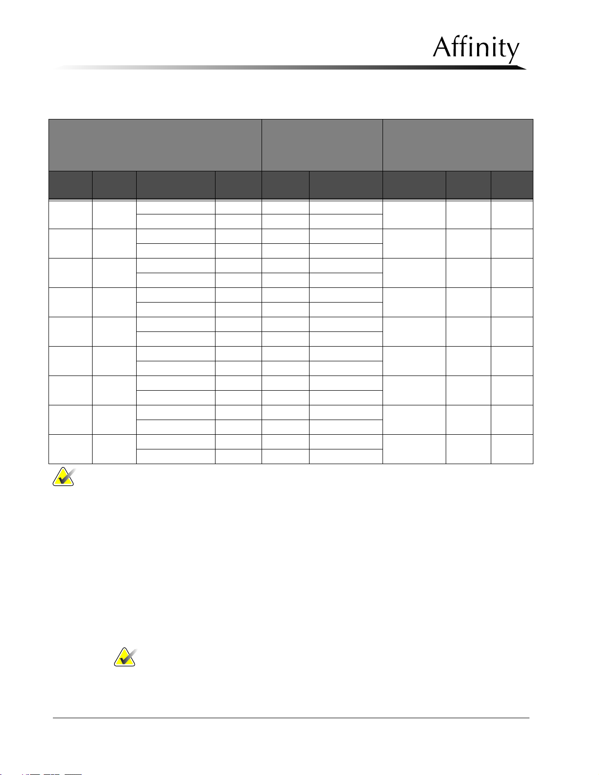
Service Manual
Chapter 4: Calibrations and Performance Checks
Automatic Exposure Control System Calibration
Table 4-6: AEC Performance Worksheet—Large Focal Spot, Mo Filter
Large Focal Spot
0.030 mm Molybdenum Filter
18 x 24 cm Bucky/
Paddle/BR-12
KODAK MIN-R-2000
Film/Cassette
kV mA Recommended
mAs OD Gain/Offset Max/-1.0 cm mAs OD
Thickness
24 95 3.0 cm G=
24 95 5.0 cm O=
25 100 3.5 cm G=
25 100 5.5 cm O=
26 100 4.0 cm G=
26 100 6.0 cm O=
27 100 4.0 cm G=
27 100 6.5 cm O=
28 100 4.5 cm G=
28 100 7.0 cm O=
29 100 4.5 cm G=
29 100 7.5 cm O=
30 100 5.0 cm G=
30 100 8.0 cm O=
31 100 5.0 cm G=
31 100 8.5 cm O=
32 100 5.5 cm G=
32 100 9.0 cm O=
Gain - Lower Thickness = 40 to
80 mAs
Offset - Higher Thickness = 240
to 350 mAs
4.0 cm
4.5 cm
5.0 cm
5.5 cm
6.0 cm
6.5 cm
7.0 cm
7.5 cm
8.0 cm
Note… Adjust thickness as necessary to achieve desired results.
5.9 Performance Test—Large Focal Spot (Rh)
This procedure ensures that the AEC system consistently produces films at the required
optical density (within 0.15 OD) using the Rh filter.
1. Select the Rhodium filter (refer to Table 4-7: AEC Performance Worksheet—Large Focal
Spot, Rh Filter).
2. Make Rh filtered exposures at 28 through 32 kV. Check the optical density of each film
to ensure that it is within ±0.15 OD of the mean optical density.
3. If necessary, make Gain and Offset adjustments. Use absorber thicknesses to make Gain
adjustments between 40 and 80 mAs. Use absorber thicknesses to make Offset adjustments between 200 mAs and 350 mAs.
Note… It may be necessary to use absorber thicknesses greater than 6.0 cm to
achieve the desired mAs when calibrating AEC using the Rhodium filter at
higher kVs.
4-22 P/N 9-500-0255
Page 79
Service Manual
Chapter 4: Calibrations and Performance Checks
Automatic Exposure Control System Calibration
Table 4-7: AEC Performance Worksheet—Large Focal Spot, Rh Filter
Large Focal Spot
0.025 mm Rhodium Filter
SRL 2000 Bucky/
Paddle/BR-12
KODAK MIN-R-2000
Film/Cassette
kV mA Recommended
mAs OD Gain/Offset Max/-1.0 cm mAs OD
Thickness
28 100 4.5 cm G=
28 100 7.0 cm O=
29 100 4.5 cm G=
29 100 7.5 cm O=
30 100 5.0 cm G=
30 100 8.0 cm O=
31 100 5.0 cm G=
31 100 8.0 cm O=
32 100 5.5 cm G=
32 100 8.5 cm O=
Note… Adjust thickness as necessary to achieve desired results.
5.10 Initial Calibration—Small Focal Spot (Mo)
This procedure will make gain and offset adjustments to the automatic exposure control
system for small focal spot exposures. Exposures used to adjust the offset must be taken
between 65 mAs and 130 mAs, and exposures used to adjust the gain must be taken
between 6 mAs and 14 mAs. Always take sample exposures, then adjust the amount of
attenuation to achieve the proper mAs before making gain or offset adjustments.
Gain - Lower Thickness = 40 to
80 mAs
Offset - Higher Thickness = 240
to 350 mAs
6.0 cm
6.5 cm
7.0 cm
7.0 cm
7.5 cm
Note… Before starting this procedure, select the small focal spot, then set the Gain
and Offset values to the values used at 25 kV for the Large Focal spot.
1. Remove the Bucky device and install the Magnification Table. Always use the same cas-
sette for all AEC calibrations.
2. Set the unit for an exposure at 25 kV, Small focal spot, Mo filter, Mag Auto-Time.
3. Place 2.0 cm of BR-12 or PMMA on the breast platform, centered laterally, and extend-
ing 1.0 cm over the chest wall edge. Place the AEC detector in the position closest to the
chest wall.
4. Place the AEC detector in the position closest to the chest wall. Take an exposure,
develop the film, then measure the optical density (OD).
Note… Always measure the Optical Density with the lower edge of the film flush
with the front edge of the Densitometer and centered side-to-side
(approximately 5.0 cm into film plane).
5. Make Gain adjustments to calibrate the Optical Density to the value requested by the
customer. Increase the Gain value if the density is too high. To maintain mAs require-
P/N 9-500-0255 4-23
Page 80

Service Manual
Chapter 4: Calibrations and Performance Checks
Automatic Exposure Control System Calibration
ments (6 - 14 mAs), it may be necessary to increase or decrease the amount of BR-12 or
PMMA used.
6. Make another exposure, develop the film, then measure the Optical Density.
7. Repeat Steps 5 and 6 as necessary, to obtain the mean OD requirement (±0.15 OD).
8. Replace the 2.0 cm absorber with the 5.0 cm absorber. Using the same techniques as in
Steps 5 and 6, make an exposure, develop the film, then measure the Optical Density.
9. Make Offset adjustments to calibrate the Optical Density to the value requested by the
customer. Increase the Offset value if the density is too high. To maintain mAs requirements (65 - 130 mAs), it may be necessary to increase or decrease the amount of BR-12
or PMMA used.
10. Make another exposure, develop the film, then measure the Optical Density.
11. Repeat Steps 9 and 10 as necessary, to obtain the mean OD requirement (±0.15 OD).
12. Replace the 5.0 cm absorber with the 2.0 cm absorber, make an exposure, develop the
film, then measure the Optical Density. Ensure the Optical Density reading is within
±0.15 OD of the exposure at 5.0 cm. If necessary, repeat the entire procedure to bring
both the 2.0 cm and the 5.0 cm exposures within the specified requirements.
13. Change the Gain, Offset and M-Density (if required) values for each of the remaining
small focal spot kV stations to the Gain, Offset, and M-Density values obtained in this
procedure.
5.11 kV Tracking - Small Focal Spot (Mo)
This procedure ensures that the automatic exposure control system will produce proper OD
films at intermediate kV levels, small focus, with 4.0 cm of attenuation.
1. Place 4.0 cm of BR-12 on the Magnification Table - centered laterally - positioned 1.0
cm over the chest wall edge.
2. Set the unit for an Auto-Time exposure, Small focal spot, Mo filter.
3. Make exposures at 25 through 30 kV. Check the optical density tracking each film.
4. If necessary, adjust Gain and Offset at each kV station to maintain OD within ±0.15 OD
of the mean optical density value.
5.12 Initial Calibration—Small Focal Spot (Rh)
This procedure will make gain and offset adjustments to the automatic exposure control
system for small focal spot exposures. Exposures used to adjust the offset must be taken
between 65 mAs and 130 mAs, and exposures used to adjust the gain must be taken
between 6 mAs and 14 mAs. Always take sample exposures, then adjust the amount of
attenuation to achieve the proper mAs before making gain or offset adjustments.
Note… Before starting this procedure, select the small focus, then set the Gain and
Offset values to the values used at 26 kV for the Large Focal spot.
1. Set the unit for an exposure at 28 kV, Small focal spot, Rh filter, Mag Auto-Time.
2. Place 2.5 cm of BR-12 or PMMA on the breast platform, centered laterally, and extending 1.0 cm over the chest wall edge. Place the AEC detector in the position closest to the
chest wall.
3. Place the AEC detector in the position closest to the chest wall. Take an exposure,
develop the film, then measure the optical density (OD).
4-24 P/N 9-500-0255
Page 81

Service Manual
Chapter 4: Calibrations and Performance Checks
Automatic Exposure Control System Calibration
Note… Always measure the Optical Density with the lower edge of the film flush
with the front edge of the Densitometer and centered side-to-side
(approximately 5.0 cm into film plane).
4. Make Gain adjustments to calibrate the Optical Density to the value requested by the
customer. Decrease the Gain value if the density is too high. To maintain mAs requirements (6 - 14 mAs), it may be necessary to increase or decrease the amount of BR-12 or
PMMA used.
5. Make another exposure, develop the film, then measure the Optical Density.
6. Repeat Steps 4 and 5 as necessary, to obtain the mean OD requirement (±0.15 OD).
7. Replace the 2.5 cm absorber with the 6.0 cm absorber. Using the same techniques as in
Steps 5 and 6, make an exposure, develop the film, then measure the Optical Density.
8. Make Offset adjustments to calibrate the Optical Density to the value requested by the
customer. Decrease the Offset value if the density is too high. To maintain mAs requirements (65 - 130 mAs), it may be necessary to increase or decrease the amount of BR-12
or PMMA used.
9. Make another exposure, develop the film, then measure the Optical Density.
10. Repeat Steps 8 and 9 as necessary, to obtain the mean OD requirement (±0.15 OD).
11. Replace the 6.0 cm absorber with the 2.5 cm absorber, make an exposure, develop the
film, then measure the Optical Density. Ensure the Optical Density reading is within
±0.15 OD of the exposure at 6.0 cm. If necessary, repeat the entire procedure to bring
both the 2.5 cm and the 6.0 cm exposures within the specified requirements.
12. Change the Gain, Offset and M-Density (if required) values for each of the remaining
small focal spot kV stations to the Gain, Offset, and M-Density values obtained in this
procedure.
5.13 Starting AEC Values - Small Focal Spot
This procedure inputs recommended starting AEC values for 22 through 24 kV, and for 31
through 39 kV for the Small focus.
1. Input the values for Gain, Offset and AEC Density used at 25 kV into the corresponding
fields for 20 through 24 kV for Mo.
2. Input the values for Gain, Offset and AEC Density used at 30 kV into the corresponding
fields for 31 through 35 kV for Mo.
3. Select the Rhodium (Rh) filter. Input the values for Gain, Offset, and M-Density used at
32 kV into the corresponding fields for 33 through 39 kV for Rh.
4. Re-select the Molybdenum filter.
5.14 Performance Test - Small Spot (Mo)
This procedure ensures that the AEC system consistently produces films at the required
optical density (within 0.15 OD) using the Mo filter.
1. Make a small focal spot exposure using the phantom thicknesses and kV combinations
shown in the worksheet at the end of this procedure (refer to Table 4-8: AEC Performance Worksheet—Small Focal Spot, Mo Filter). In the space provided, record the mAs
and optical density values.
2. Verify that the maximum optical density deviation on each film does not exceed ±0.15
OD. If it does, repeat the Gain and Offset adjustments for the kV’s that are out of tolerance.
P/N 9-500-0255 4-25
Page 82
Service Manual
Chapter 4: Calibrations and Performance Checks
Automatic Exposure Control System Calibration
Note… Do not readjust Gain or Offset at 26 kV (initial calibration).
Table 4-8: AEC Performance Worksheet—Small Focal Spot, Mo Filter
Small Focal Spot
0.030 mm Molybdenum Filter
kV mA Recommended
Thickness
mAs OD Gain/Offset Max/-1 cm mAs OD
Mag Table/Paddle/BR-12
KODAK MIN-R-2000 Film/
Cassette
Gain - Lower Thickness = 6 to
14 mAs
Offset - Higher Thickness = 65
to 130 mAs
24 28 1.5 cm G=
24 28 4.5 cm O=
25 30 2.0 cm G=
25 30 4.5 cm O=
26 30 2.0 cm G=
26 30 5.0 cm O=
27 30 2.5 cm G=
27 30 5.5 cm O=
28 30 2.5 cm G=
28 30 6.0 cm O=
29 30 3.0 cm G=
29 30 6.5 cm O=
30 30 3.0 cm G=
30 30 6.5 cm O=
31 30 3.5 cm G=
31 30 7.0 cm O=
32 30 3.5 cm G=
32 30 7.5 cm O=
Note… Adjust thickness as necessary to achieve desired results.
3.5 cm
3.5 cm
4.0 cm
4.5 cm
5.0 cm
5.5 cm
5.5 cm
6.0 cm
6.5 cm
5.15 Performance Test - Small Spot (Rh)
This procedure ensures that the AEC system consistently produces films at the required
optical density (within 0.15 OD) using the Rh filter, small focus.
1. Select the Rhodium filter. Enter the values for Gain, Offset and AEC Density obtained for
the Mo filter as the starting values for the Rh filter (refer to Table 4-9: AEC Performance
Worksheet—Small Focal Spot, Rh Filter).
2. Make Rh filtered exposures at 28 through 32 kV. Check the optical density of each film
to ensure that it is within ±0.15 OD of the mean optical density.
3. If necessary, make Gain and Offset adjustments. Use absorber thicknesses to make Gain
adjustments between 7 mAs and 10 mAs. Use absorber thicknesses to make Offset
adjustments between 70 mAs and 100 mAs.
4-26 P/N 9-500-0255
Page 83
Service Manual
Chapter 4: Calibrations and Performance Checks
Automatic Exposure Control System Calibration
Table 4-9: AEC Performance Worksheet—Small Focal Spot, Rh Filter
Small Focal Spot
Mag Table/Paddle/BR-
0.025 mm Rhodium Filter
KODAK MIN-R-2000
Film/Cassette
kV mA Recommended
mAs OD Gain/Offset Max/-1 cm mAs OD
Thickness
28 30 2.5 cm G=
28 30 6.0 cm O=
29 30 3.0 cm G=
29 30 6.5 cm O=
30 30 3.0 cm G=
30 30 6.5 cm O=
31 30 3.5 cm G=
31 30 7.0 cm O=
32 30 3.5 cm G=
32 30 7.5 cm O=
Note… Adjust thickness as necessary to achieve desired results.
5.16 HTC Factor (Offset) Calibration
This procedure is only applicable for those systems with an HTC Bucky.
12
Gain - Lower Thickness = 6 to
14 mAs
Offset - Higher Thickness = 65
to 130 mAs
5.0 cm
5.5 cm
5.5 cm
6.0 cm
6.5 cm
1. Set unit to Calibration Screen #3, set the HTC C-THK threshold for 6.0.
2. Set unit to Calibration Screen #2.
3. Set the unit for an Auto-Time exposure at 26 kV, Large focus, Mo filter. Set the Film data
field to the screen-film combination loaded in the cassette.
4. Place the amount of BR-12 or PMMA acrylic that was used in the final 26 kV, low attenuation exposure from Table 4-6 on the Bucky, centered laterally, and extending approximately 1.0 cm over the chest wall edge.
5. Place the AEC detector in the position closest to the chest wall. Take an exposure,
develop the film, then measure the optical density (OD).
6. On Calibration Screen #2, select HTC FACTOR and adjust as necessary to set OD to
match the OD reading from the 26 kV, low attenuation exposure on Table 4-6 (+
OD). Record final results on Table 4-10.
Table 4-10: HTC Factor Worksheet
HTC FACTOR
kV ReducedmAThickness mAs OD HTC Factor
26 30
5.17 Large Bucky (24 x 30 cm) Factor Calibration
1. Set unit to Calibration Screen #2.
0.05
P/N 9-500-0255 4-27
Page 84
Service Manual
Chapter 4: Calibrations and Performance Checks
Automatic Exposure Control System Calibration
2. Set the unit for an Auto-Time exposure at 26 kV, Large focus, Mo filter. Set the Film data
field to the screen-film combination loaded in the cassette.
3. Place 4.0 cm of BR-12 or PMMA acrylic on the 18 x 24 cm Bucky, centered laterally
over the AEC detectors. Lower the compression device onto the BR-12.
4. Take an exposure, develop the film, then measure the optical density (OD). Write the
mA and OD in the place provided on the Large Bucky Factor Worksheet (Table 4-11) for
the 18 x 24 cm Bucky.
5. Remove the 18 x 24 cm Bucky.
6. Place a 24 x 30 cm Bucky on the system and set the unit for an Auto-Time exposure at
26 kV, Large focus, Mo filter. Set the Film data field to the screen-film combination
loaded in the cassette.
7. Place 4.0 cm of BR-12 or PMMA acrylic on the 24 x 30 cm Bucky, centered laterally
over the AEC detectors. Lower the compression device onto the BR-12.
8. Take an exposure, develop the film, then measure the optical density (OD). Write the
mA and OD in the place provided on the Large Bucky Factor Worksheet (Table 4-11) for
the 24 x 30 cm Bucky.
9. Divide the 18 x 24 cm Bucky mAs by the 24 x 30 cm Bucky mAs (as shown in Table 4-
11). This is the Large Bucky Factor.
10. On Calibration Screen #2, select LgBky FACTOR and adjust as necessary to match the
calculated Large Bucky Factor.
11. Take an exposure with the 24 x 30 cm Bucky and develop the film. Measure the OD.
Adjust the Large Bucky Factor until the large Bucky OD is within 0.10 of the small Bucky
OD.
Table 4-11: Large Bucky Factor Worksheet
18 x 24 cm Bucky 24 x 30 cm Bucky
Thickness mAs OD Thickness mAs OD
4.0 cm 4.0 cm
Final Large Bucky Factor _________
5.18 Compression Thickness Threshold Adjustment
Note… For this adjustment the unit must be in 100 mA mode. Ensure that the
Compression Thickness Threshold is 1.0 cm at the start of this procedure.
1. For units with no HTC Bucky, go to Step 3, for units with HTC Bucky, go to Step 2.
12. Set unit to Calibration Screen #3, set the HTC C-THK threshold for 1.0 cm.
13. Set unit to Calibration Screen #2.
14. Install the 18 x 24 cm Bucky onto the IRSD and insert a loaded cassette. Always use the
same cassette and Bucky for all calibration steps.
15. Set the unit for an Auto-Time exposure at 25 kV, Large focus, Mo filter. Set the Film data
field to the screen-film combination loaded in the cassette.
16. Place the amount of BR-12 or PMMA acrylic that was used in the final 25 kV, low attenuation exposure from Table 4-6 on the Bucky, centered laterally and extending 1.0 cm
over the chest wall edge. Use motorized compression to lower the compression paddle
onto the phantom material.
4-28 P/N 9-500-0255
Page 85

Service Manual
Chapter 4: Calibrations and Performance Checks
Automatic Exposure Control System Calibration
17. Insert a loaded cassette into the Bucky, then make a 25 kV Auto-Time exposure. Record
the mAs value (as point “A”) on the semi log worksheet (Table 4-12).
18. Release compression and place the amount of BR-12 or PMMA acrylic that was used in
the final 25 kV, high attenuation exposure from Table 4-6 on the Bucky. Reapply compression, then make a second exposure. Record this mAs value (as point “B”) on the
semi log worksheet.
19. Draw a line between points “A” and “B” on the semi log. Follow the left side of the graph
and locate the 80 mAs point. Draw a straight line and intercept the line between the 2
points.
20. Draw a vertical line from that point to the bottom of the graph and note the compression
thickness value indicated. This is the compression thickness threshold value.
21. On Calibration Screen 3, highlight HTC C-THK and change the displayed value to the
value calculated on the graph.
P/N 9-500-0255 4-29
Page 86
Service Manual
Chapter 4: Calibrations and Performance Checks
Automatic Exposure Control System Calibration
Table 4-12: Compression Thickness Threshold Semi-Log
500
400
300
200
100
90
80
70
60
50
40
30
20
mAs↑
Thickness→
10
0
1cm 2cm 3cm 4cm 5cm
6cm
4-30 P/N 9-500-0255
Page 87

Chapter 4: Calibrations and Performance Checks
5.19 C-arm Safety Function Check
The C-arm Safety Function Check procedures should be performed on a semi-annual basis or
whenever the C-arm Safety Microprocessor Board or Load Cell has been replaced.
1. Set C-arm at 0°. Place an obstruction (padded chair, table) below C-arm.
2. Press and hold C-arm down button until C-arm moves onto obstruction.
3. Verify C-arm stops automatically. If not, perform the C-arm Safety Microprocessor Board
Calibration procedures as per Section 8.4.
4. Check that all C-arm down buttons are disabled.
5. Verify “Safety Switch” alert appears on the display. (Alert Code 6, see Chapter 5, Section
3.2, Table 5-2.)
6. Press C-arm Up button and verify C-arm moves upward.
7. Press Reset on Control Panel to clear message. Remove obstruction from C-arm area.
Service Manual
Automatic Exposure Control System Calibration
P/N 9-500-0255 4-31
Page 88

Service Manual
Chapter 4: Calibrations and Performance Checks
Performance Checks
6.0 Performance Checks
This section of the manual contains the performance checks which verify system
performance and compliance, including verification of the x-ray generating system, and
checks for x-ray and leakage.
After servicing the X-ray System, the following checks must be completed.
• Half-Value Layer (Section 6.1)
• Reproducibility and Linearity in Manual Mode (Section 6.2)
• Reproducibility in Auto-Time Mode (Section 6.3)
• Reproducibility in Auto kV Mode (Section 6.4)
• Reproducibility in Auto-Filter Mode (Section 6.5)
The following are standard system performance checks.
• Bucky Device Performance (Section 6.6)
• AEC Limits Performance Check (Section 6.7)
• System Level Functional Check (Section 6.8)
• Optical Density (User’s Preference) Verification (Section 6.9)
The following checks verify that the mammography unit’s shielding meets requirements.
Perform the appropriate check(s) after servicing the Tubehead or the Image Receptor Support
Device.
• Leakage Check - IRSD (Section 6.10)
• Leakage Check - Tubehead (Section 6.11)
6.1 Half-Value Layer
This compliance check verifies the quality of the x-ray beam and ensures that the half-value
layer (HVL) meets the requirements set forth by the FDA, 21CFR, and the recommendations
by the ACR/CDC.
This check requires the use of the following equipment:
• Dosimeter
• Type 1100 aluminum filter pack (99.9% pure)
• Radiation Meter and Probe
4-32 P/N 9-500-0255
Page 89
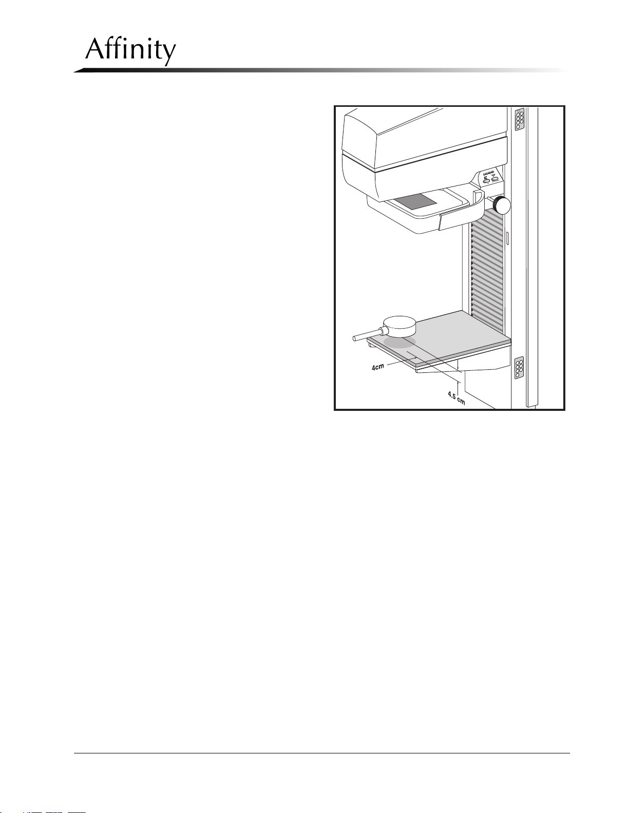
Service Manual
Chapter 4: Calibrations and Performance Checks
Performance Checks
1. Place a radiation probe 4.5 cm
above the image receptor support device. Position the probe
4.0 cm from the chest wall
edge, and center it laterally with
respect to the left and right
edges of the IRSD (Figure 4-6).
Set the meter functions switch
to milliroentgens.
2. Install the 18 x 24 cm compres-
sion paddle upside-down on the
compression device. Raise the
compression device completely.
Ensure the probe’s meter is posi-
tioned so that it can be read
from behind the unit’s radiation
shield.
3. In the RUN MODE, set the unit
for a Manual Mode exposure at
30 kV, 70 mAs, Large focal spot,
Mo filter.
4. Insert the Auto-aperture into the
tubehead slot, conduct the
exposure, and record the milliroentgen reading on the semilog (Table 4-13).
5. Place a 0.2 mm aluminum filter
(99.9% pure aluminum) on the surface of the compression paddle, directly beneath the
x-ray tube port (Figure 4-6). Using the same technique factors as in Step 3, make another
exposure and record the milliroentgen reading on the semi-log.
6. Repeat Step 5 with additional 0.1 mm sheets of aluminum between the x-ray tube port
and the radiation probe. Record the milliroentgen reading on the semi-log after each
exposure until the reading is less than one-half the original step #4 exposure reading
(without aluminum).
7. Draw a line on the semi-log through the plotted mR readings. It may be necessary to
draw the line to achieve a “best fit” path (in cases where the plotted readings are not linear).
8. Determine the exact half-value of the step #4 mR reading and record this on the semi-
log. Draw a horizontal line, starting from this plot, across the semi-log until it intersects
with the line plotted in Step 7.
9. Draw a vertical line through the intersection to the bottom of the semi-log. This is the
half-value layer. Verify that the half-value layer is greater than 0.33 mm AL, and less than
0.42 mm AL (Molybdenum filter).
10. Select the Rhodium (Rh) filter, then repeat Steps 4 through 9 to obtain the half-value
layer for the Rhodium filter. Verify that the half-value layer is greater 0.33 mm AL, and
less than 0.49 mm AL (Rhodium filter).
Figure 4-6: Half-Value Layer Setup
P/N 9-500-0255 4-33
Page 90
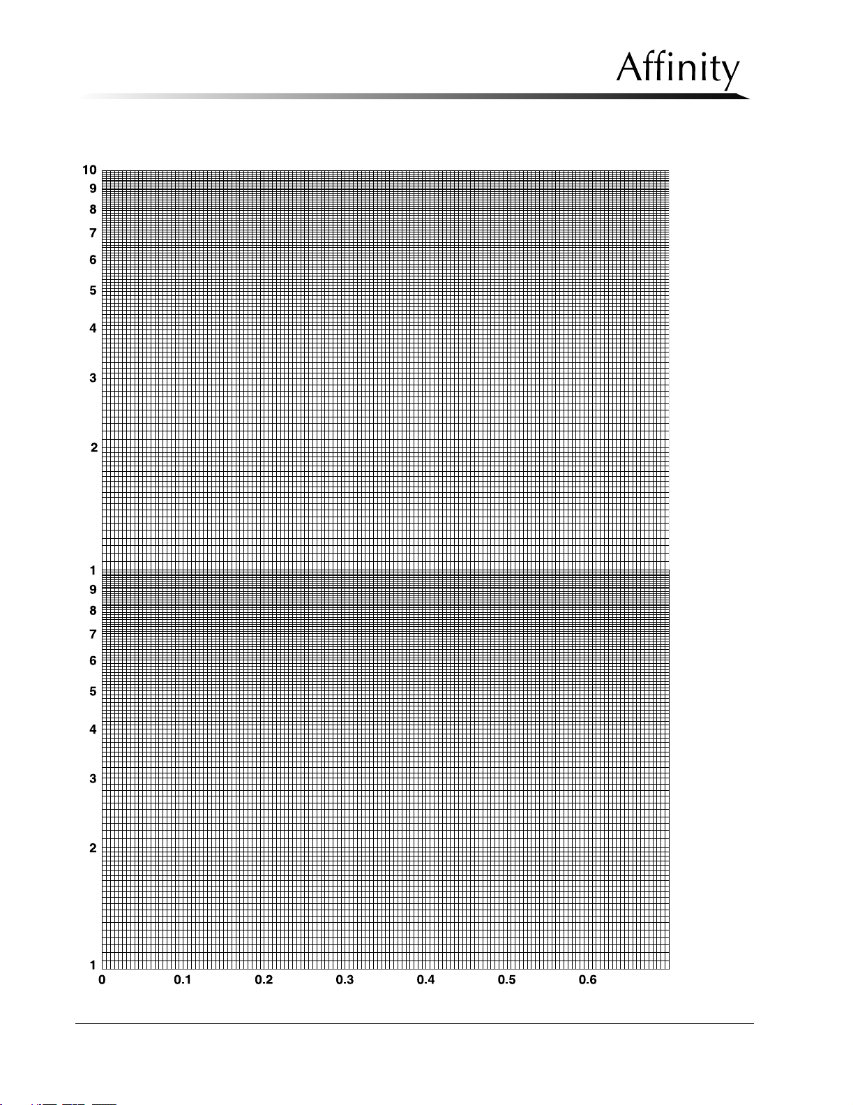
Service Manual
Chapter 4: Calibrations and Performance Checks
Performance Checks
Table 4-13: Half-Value Layer Semi-Log
mR
4-34 P/N 9-500-0255
Page 91
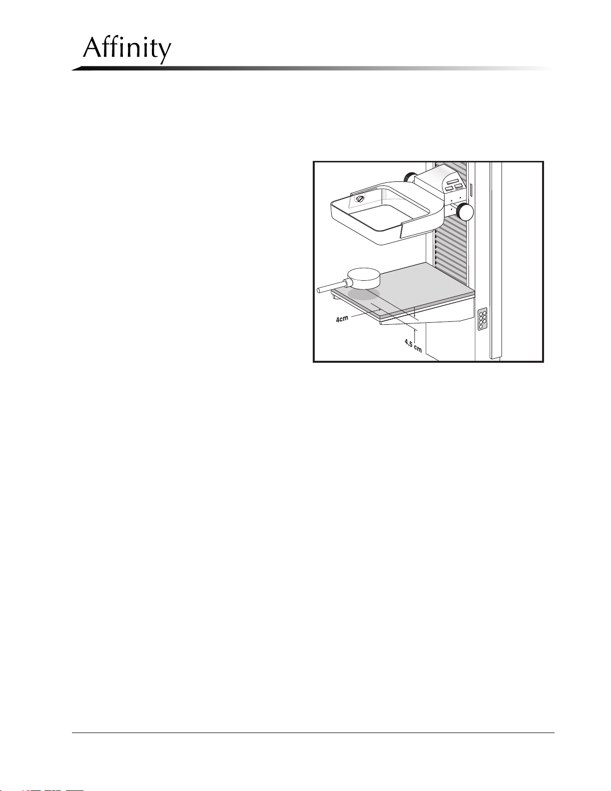
Chapter 4: Calibrations and Performance Checks
6.2 Reproducibility and Linearity in Manual Mode
The following test verifies that the x-ray system (including the controls and x-ray tube) is
operating consistently. Record the readings and mathematical calculations in the
Reproducibility & Linearity Worksheets.
1. Set the radiation probe mod-
ule to read exposure in milliroentgens. Fixture the probe
to set it 4.5 cm above the
IRSD (as shown in Figure 4-
7). Position the probe 4.0 cm
from the chest wall edge,
and center it laterally with
respect to the left and right
edges of the IRSD.
2. Turn the system ON and illu-
minate the light field. Limit
the beam to approximately
the size of the probe head.
Reposition the probe head to
center its detector in the
beam. Align the surface of
the probe so that it stays perpendicular to the beam axis.
3. Set the unit for a Manual
Mode exposure at 25 kV, 60 mAs, large Focal Spot, Mo Filter. Conduct the exposure,
then record the milliroentgen reading on the Reproducibility Worksheet (Table 4-14).
4. Change the technique factors for both kV and mAs, then return them to 25 kV and 60
mAs. Conduct a second exposure and record the milliroentgen reading on the Worksheet.
5. Continue to randomly change the technique settings for kV and mAs, then return to 25
kV and 60 mAs and take an exposure. Record the milliroentgen reading on the worksheet until ten individual readings have been recorded.
6. Compute and record the average milliroentgen reading. Subtract each actual reading
from the average, and square each difference. Add the squares and divide the sum by
nine. Then take the square root of the result.
7. Divide the number calculated in Step 6 by the average milliroentgen reading to obtain
the coefficient of variation. The coefficient of variation must be less than 0.05.
8. Leave the configuration on the image receptor support the same. Change the technique
settings to 25 kV and 20 mAs. Make an exposure and record the milliroentgen reading
and the mAs value on the screen on the Linearity Worksheet (Table 4-15).
9. Repeat Step 8, changing the mAs to 60, 100, 150, 200, 250, 300, 400 and 500. Record
milliroentgens and mAs at each setting.
10. Divide each milliroentgen reading by its corresponding mAs value.
11. For each pair of successive tests, calculate the difference between each corresponding
Step 10 result.
12. For each pair of successive tests, calculate the sum of each Step 10 result.
Figure 4-7: Reproducibility & Linearity Check Setup
Service Manual
Performance Checks
P/N 9-500-0255 4-35
Page 92

Service Manual
Chapter 4: Calibrations and Performance Checks
Performance Checks
13. Divide each Step 11 difference value by each Step 12 sum value. If the result for any pair
exceeds 0.10, the test is considered failed.
14. Repeat Steps 8 through 13 using the Small Focal Spot.
15. If the unit fails any part of the above test, first recheck all calculations, then repeat the
tests. Failure to meet these performance standards indicates the need to check the x-ray
tube’s kV, mA, and mR outputs.
6.3 Reproducibility in Auto-Time Mode
The following test verifies that the automatic exposure control system is operating
consistently in the Auto-time exposure mode. Record the readings and mathematical
calculations in the Reproducibility Worksheet (Table 4-14).
1. On the IRSD, place 4.0 cm of acrylic attenuation on an empty cassette. Position a 10square cm radiation probe on top of the acrylic.
2. Center the probe position directly above the AEC sensor. Use the light field lamp to visualize the x-ray field and collimate appropriately so that just the probe is exposed.
3. Set the unit for an Auto-time exposure at 25 kV, Mo Filter, Large Focal Spot. Conduct ten
exposures. Record the milliroentgen and post-exposure mAs readings for each exposure.
4. Calculate the average mR reading and subtract each actual reading from the average.
Square each difference. Add the squares and divide their sum by 9. Take the square root
of the result.
5. Divide the number obtained in Step 4 by the average milliroentgen reading. The quotient
- or coefficient of variation - must be less than 0.05.
6. If the coefficient of variation greater than 0.05, check the calibration of the Automatic
Exposure Control System.
6.4 Reproducibility in Auto-kV Mode
The following test verifies that the automatic exposure control system is operating
consistently in the Auto-kV exposure mode. Record the readings and mathematical
calculations in the Reproducibility Worksheet (Table 4-14).
1. Set up the mammography system and radiation probe exactly as in Step 1 of the AutoTime Reproducibility Check (Section 6.3).
2. Set the unit for an Auto-kV exposure, using the Mo Filter and the Large Focal Spot. Conduct ten exposures. Record the milliroentgen and post-exposure mAs readings for each
exposure.
3. Calculate the average mR reading and subtract each actual reading from the average.
Square each difference. Add the squares and divide their sum by 9. Take the square root
of the result.
4. Divide the number obtained in Step 3 by the average milliroentgen reading. The quotient
(called the coefficient of variation) must be less than 0.05.
5. If the coefficient of variation is greater than 0.05, check the calibration of the Automatic
Exposure Control System.
6.5 Reproducibility in Auto-Filter Mode
The following test verifies that the automatic exposure control system is reproducible in the
Auto-Filter exposure mode. Failure to meet this performance test indicates the need to check
the calibration of the Automatic Exposure Control System.
4-36 P/N 9-500-0255
Page 93

Service Manual
Chapter 4: Calibrations and Performance Checks
Performance Checks
1. On the IRSD, place 6.0 cm of acrylic attenuation on an empty cassette. Position a radia-
tion probe (10 square cm) on top of the phantom.
2. Align the probe position with the AEC sensor at front center on the IRSD. Use the light
field and collimate the x-ray field to the approximate size of the probe.
3. Set the unit for an Auto-Filter exposure using the Large focal spot. Make 10 exposures
and record the milliroentgen readings for each exposure.
4. Calculate the average milliroentgen reading. Subtract each actual reading from the aver-
age. Square each difference. Add the squares and divide their sum by 9. Take the square
root of the result.
5. Divide the number obtained in Step 3 by the average milliroentgen reading. The quo-
tient, called the coefficient of variation, must be less than 0.05.
Note … To calculate the coefficient of variation, use the Reproducibility Worksheet
(Table 4-14) which sequences the steps to calculate the quotient. Table 4-14
also provides a formula to calculate the quotient using a statistical
calculator. Note that the kV and mAs values are not set for this check.
P/N 9-500-0255 4-37
Page 94
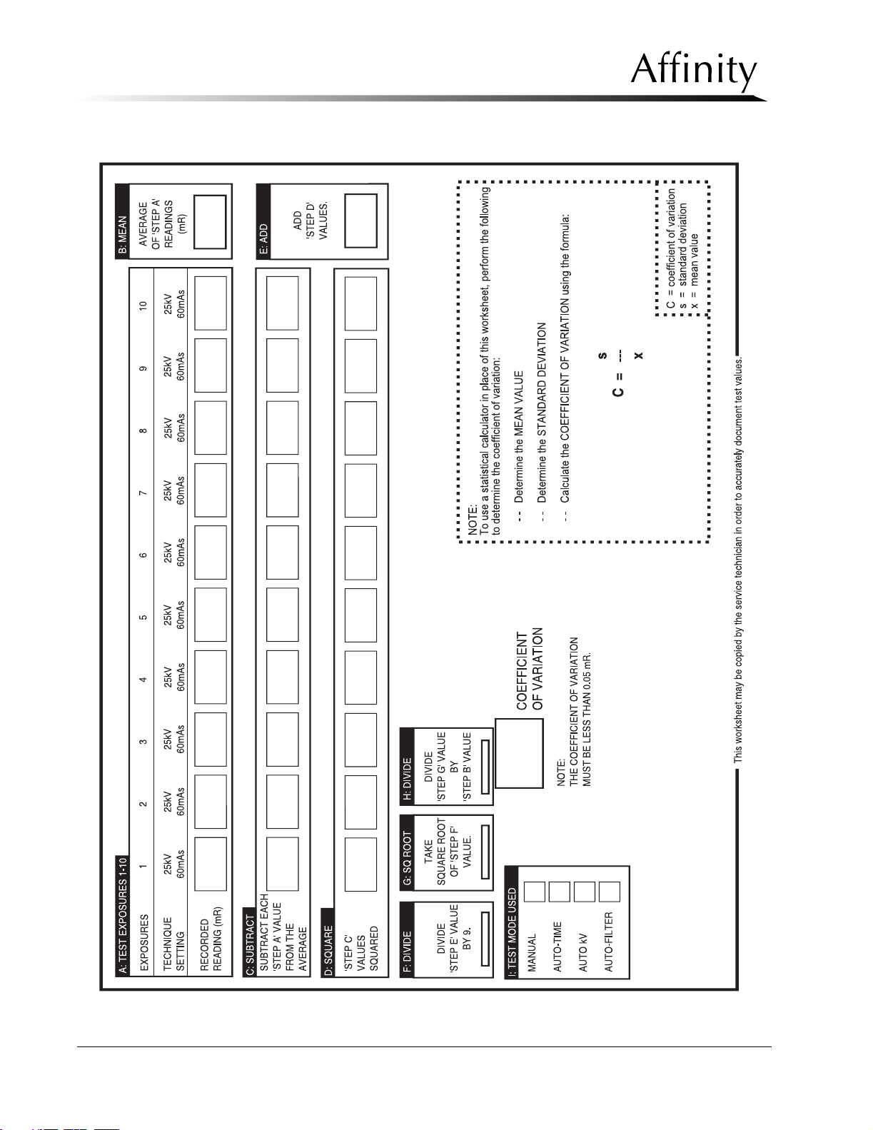
Service Manual
Chapter 4: Calibrations and Performance Checks
Performance Checks
Table 4-14: Reproducibility Worksheet
4-38 P/N 9-500-0255
Page 95
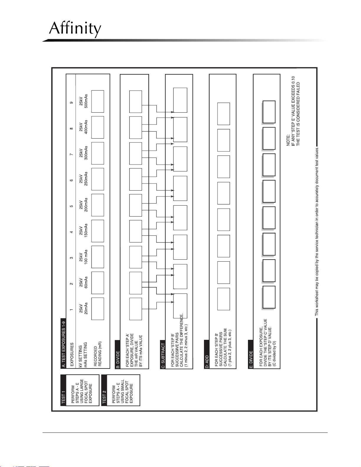
Service Manual
Chapter 4: Calibrations and Performance Checks
Performance Checks
Table 4-15: Linearity Worksheet
P/N 9-500-0255 4-39
Page 96

Service Manual
Chapter 4: Calibrations and Performance Checks
Performance Checks
6.6 Bucky Device Performance Check
Perform this check before utilization of a new SRL 2000 or HTC Bucky device. This
procedure requires the user to make exposures to check for grid lines (SRL 2000 Bucky) or
grid patterns (HTC Bucky) on the developed film.
Mount the 18 x 24 cm Bucky device on the IRSD. Be sure the electrical connection is made.
This procedure requires exposing and developing films. It will be necessary to place
attenuation between the tubehead and the Bucky for these tests.
Note… Use the same Bucky device, cassette, and film type for all exposures.
1. Rotate the C-arm to 0°. Set the unit for an Auto-Time, 25 kV exposure, Large spot, Normal density. Select the Film Type being used.
2. Place a loaded cassette in the Bucky device, then place 2.0 cm of BR-12 (or PMMA
acrylic) on the Bucky Device. Hold the attenuation in place with the Compression
Device.
3. Make an exposure. Verify a low mAs reading is obtained (nominally between 12 and 40
mAs, dependent on film speed). If the mAs reading is above or below the specified
range, add attenuation to increase mAs, or remove attenuation to decrease mAs.
4. Reload the Bucky (using the same cassette and film type), and repeat the exposure. Verify that the mAs falls within the specified range. If it does, remove the cassette and
develop the film. Verify the absence of grid lines (SRL 2000 Bucky) or grid patterns (HTC
Bucky) in the developed film.
5. Place 5.0 cm of BR-12 (or PMMA acrylic) on the Bucky and hold it in place with the
paddle. Reload the same cassette with the same film type, then load it into the same
Bucky.
6. Make an exposure using the technique factors from Step 1. Verify a high mAs reading is
obtained (nominally between 200 and 400 mAs, dependent on film speed). If the mAs
reading is above or below the specified range, add attenuation to increase mAs, or
remove attenuation to decrease mAs.
7. Reload the Bucky (using the same cassette and film type), and repeat the exposure. Verify that the mAs falls within the specified range. If it does, remove the cassette and
develop the film. Verify the absence of grid lines (SRL 2000 Bucky) or grid patterns (HTC
Bucky) in the developed film.
8. Repeat Steps 1 through 7 with the C-arm rotated to -90° (grid travel in the direction of
gravitational pull). Verify the absence of grid lines (SRL 2000 Bucky) or grid patterns
(HTC Bucky) on the developed film for all exposures.
9. Repeat Steps 1 through 7 with the C-arm rotated to +90° (grid travel against the direction
of gravitational pull). Verify the absence of grid lines (SRL 2000 Bucky) or grid patterns
(HTC Bucky) on the developed film for all exposures.
10. Repeat the entire procedure for the 24 x 30 cm Bucky Device.
6.7 AEC Limits Performance Check
This check verifies that the system automatically terminates exposures whenever the
automatic exposure control circuitry senses that optimum film density cannot be obtained
within the 5 second maximum exposure time. To comply, the system must terminate
Auto-Time exposures below 5 mAs.
1. Place a lead blocker on the IRSD so that it blocks the AEC sensors within the IRSD.
4-40 P/N 9-500-0255
Page 97

Chapter 4: Calibrations and Performance Checks
2. Set the unit for an Auto-Time exposure at 28 kV, Large focal spot. Set the Density com-
pensation to +5, and select the film type being used.
3. Make an exposure and verify that the post-exposure mAs value is less than 5 mAs and
the message “ERROR 21: EXP TIME” appears. (For complete alert code definition, refer
to Chapter 5, Table 5-2.)
4. Verify that the unit displays a caution that informs the user that the calculated exposure
has exceeded the maximum. Try to make another exposure before resetting the unit and
verify that x-ray generation is prevented.
5. Clear the message by pressing Reset. Repeat the test at 35 kV, Small focal spot, and verify
the same caution appears in the message area.
6.8 System Level Functional Check
This check verifies system functionality.
1. Apply power to the system. Verify the display works, and power is applied to Gantry.
Check control panel display for alert messages.
2. Set unit for a short exposure (25 kV, 3 mAs, Manual Mode, Large Focal Spot). Take expo-
sure.
3. If no problems found with exposure, return unit to operations.
Service Manual
Performance Checks
6.9 Optical Density (Users Preference) Verification
This procedure verifies that the system falls within the users preference for optical density.
1. Remove any meter, scope, or probe from the machine that was used in any procedures
prior to beginning this verification.
2. Install the Bucky with a loaded cassette, on the IRSD.
3. Place the ACR Phantom on the IRSD, centered laterally, and positioned 1.0 cm back
from the chest wall edge.
4. Move the AEC Detectors so that they are directly under the ACR Phantom.
5. Set the unit for an exposure using the default exposure mode. Make an exposure.
6. Remove the cassette and develop the film.
7. Check the film’s optical density and verify that it is at the mean optical density as
required by the site.
8. If the optical density of the film is not within site required limits, perform the AEC Cali-
bration procedures as per Chapter 4, Section 5.0, Automatic Exposure Control System
Calibration.
6.10 IRSD Leakage Check
This check is performed at the factory and is not required at installation. However, it will be
necessary to perform this check after repairing or replacing the IRSD.
1. Connect a radiation scatter probe (100 square cm) to the readout/logic module of a radi-
ation rate meter. Set the meter’s operating mode to read in exposure in milliroentgens.
Place the readout/logic module so that it can be viewed from behind the radiation
shield.
P/N 9-500-0255 4-41
Page 98
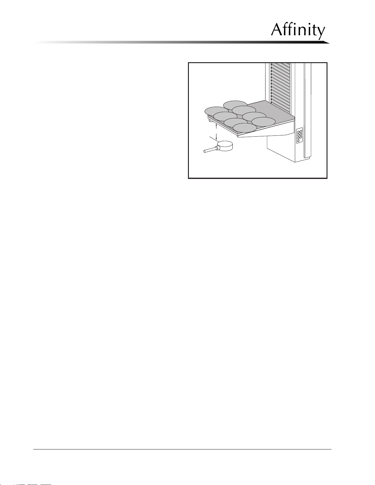
Service Manual
Chapter 4: Calibrations and Performance Checks
Performance Checks
2. Place a 1/16 inch thick (1.6
mm) sheet of lead with a 5 inch
(12.7 cm) diameter hole in it on
the IRSD. Slide this lead sheet
to position the hole at the position marked “A” (Figure 4-8).
Collimate the x-ray field to the
18 x 24 cm field size.
3. Position the probe beneath the
image receptor support relative
to the center of the hole in the
lead sheet. Raise or lower the
support stand until the probe is
exactly 5 cm below the bottom
of the IRSD. Face the probe’s
detector surface toward the xray source.
4. Apply power, then set the unit
for a Manual mode exposure at
39 kV, 220 mAs, Large focal spot. Conduct the exposure and record the mR reading. If
the reading is greater than 0.10 mR, contact L
5. Repeat this entire procedure for positions “B,” “C,” and “D” in Figure 4-8.
6. Install the 24 x 30 cm Bucky (if used). Repeat this test for positions “E”, “F”, “G” and “H”
(Figure 4-8) for the 24 x 30 cm Bucky.
7. If there are any readings greater than 0.10 mR, contact L
G
E
5 cm
SCATTER
PROBE
C
A
D
B
F
H
Figure 4-8: IRSD Shielding Check
ORAD Technical Support.
ORAD Technical Support.
6.11 X-ray Tubehead Leakage Check
This check is performed at the factory and is not required at installation. However, it will be
necessary to perform this check after repair or replacement of the tubehead housing or the
lower tubehead cover.
1. Connect a radiation scatter probe (100 square cm) to the readout/logic module of a radiation rate meter.
2. Set the meter’s operating mode to read in milliroentgens per hour (mR/Hour). Place the
readout/logic module so that it can be viewed from behind the radiation shield
4-42 P/N 9-500-0255
Page 99
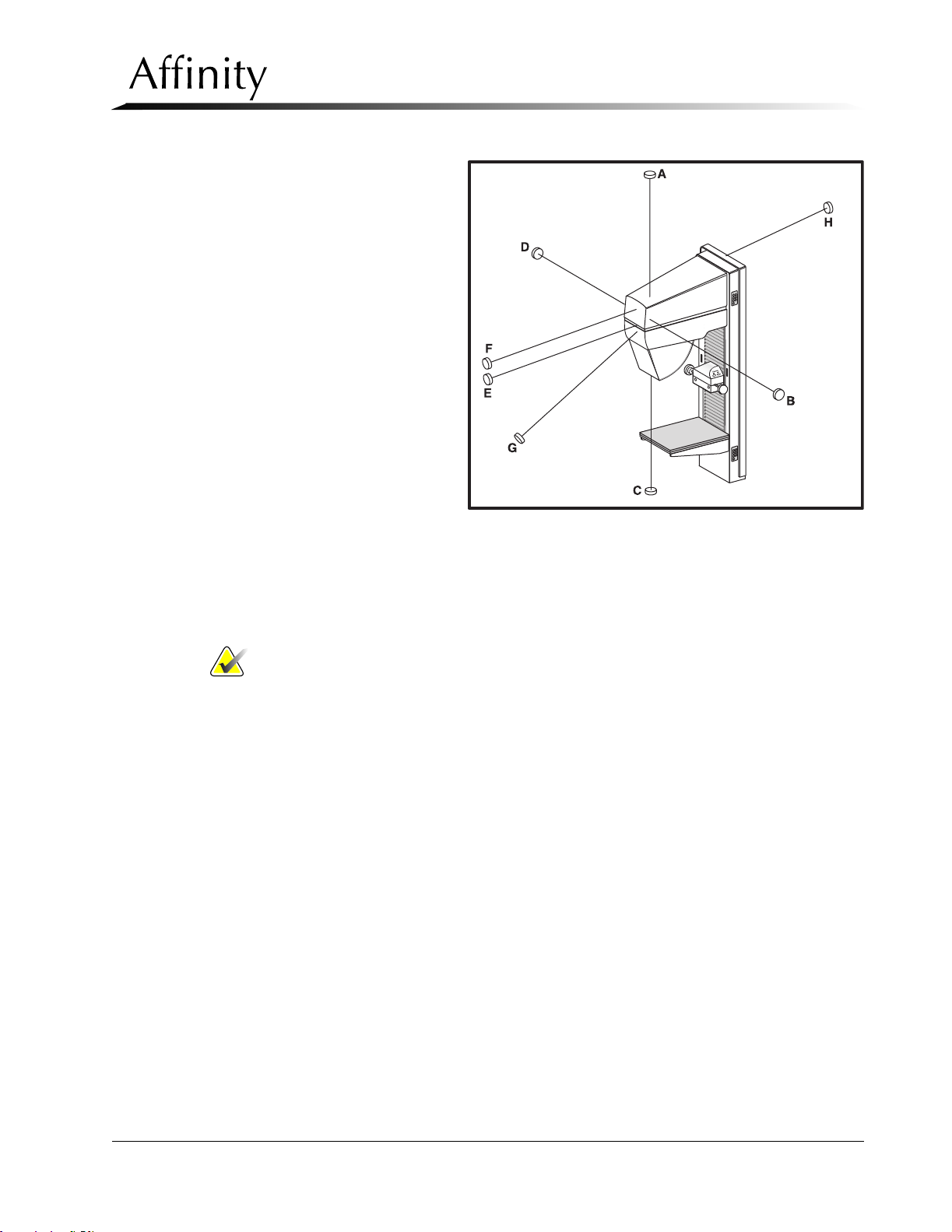
Service Manual
Chapter 4: Calibrations and Performance Checks
Performance Checks
3. Use fixtures to hold the
probe in position with
relation to the tubehead
as shown in Figure 4-9.
Position the probe at location “A”. Make sure the
distance between the
probe and the focal spot
(source) is exactly 1 meter
(39 3/8 inches).
4. Apply power, then set the
S
B
L
/
S
unit for a Manual mode
exposure at 39 kV, 220
mAs, Large focal spot.
Conduct an exposure and
record the mR reading.
5. Make exposures, using
the same technique factors, for positions “B”
through “H” (Figure 4-9).
Record each mR reading.
Figure 4-9: Tubehead Shielding Check
For position “H”, rotate
the C-arm to position the probe directly behind the tubehead. Be sure the distance
between the probe and the focal spot remains exactly one meter for each measurement
position.
N
O
T
W
E
N
M
C
Note… Any reading above 100.0 mR/Hour is unacceptable, contact L
Technical Support.
ORAD
P/N 9-500-0255 4-43
Page 100
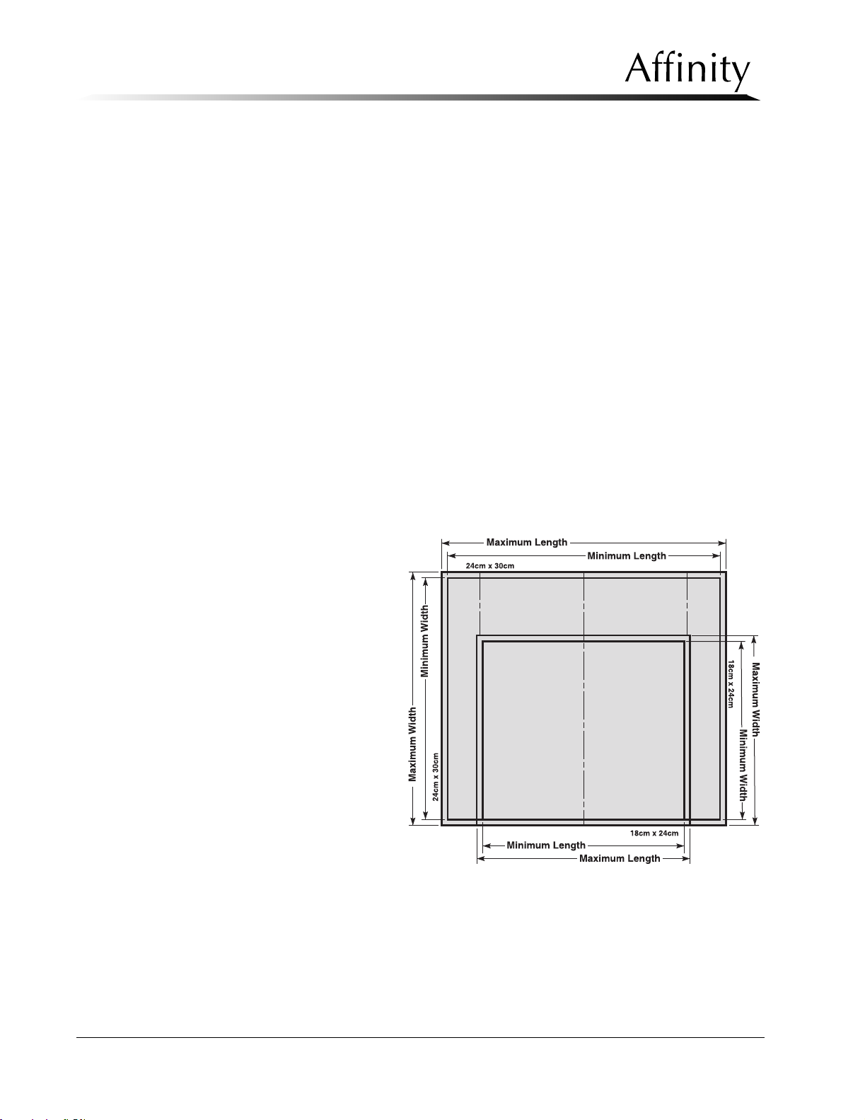
Service Manual
Chapter 4: Calibrations and Performance Checks
X-ray and Light Field Check and Alignment Procedures
7.0 X-ray and Light Field Check and Alignment Procedures
The following checks and adjustments are used to ensure that the alignment of the x-ray field
and light field are within the specifications set forth by the FDA, 21CFR, and the
recommendations by the ACR/CDC.
X-ray field alignment is the adjustment of the built-in and fixed apertures so that the x-ray
field is collimated within specified limits. The light field is adjusted to be congruent with the
x-ray field within 2% of SID.
X-ray field adjustments are performed in two stages: coarse adjustment (using a lightemitting x-ray screen) and fine adjustment (using x-ray films). The coarse adjustment
procedures employ an X-ray Beam Alignment Template that is to be used with a separate 14
x 17 cm x-ray cassette screen.
7.1 X-ray Beam Alignment Template
The translucent X-ray Beam Alignment Template (LORAD P/N 3-405-8010), shown in Figure
4-10 must be positioned on the unit’s image receptor support on top of a 14 x 17 cm cassette
screen (Lanex Med). The visible borders of the x-ray field can be compared with graduations
on the template to determine coarse x-ray field alignment
The template contains minimum and maximum borders for the left, right, and rear field
edges of the 18 x 24 cm format and the 24 x 30 cm format. For the chest wall edge, a
maximum limit (6.5 mm) is provided to adjust for chest wall edge overlap.
Always position the X-ray Beam
Alignment Template accurately
on the image receptor support
by performing the following:.
1. Place the screen (facing up)
onto the support device and
center it.
2. Move the screen forward
(away from the C-arm)
approximately 1.5". Lay the
template on top of the
screen.
3. Butt the rear edge of the
template against the C-arm
to place the image receptor
tray edge line directly
above the edge of the
image receptor support
device.
4. Center the template left-toright until the cut in edges
(at the rear of the template)
are set flush with the sides of the image receptor support.
Figure 4-10: X-ray Beam Alignment Template
4-44 P/N 9-500-0255
 Loading...