

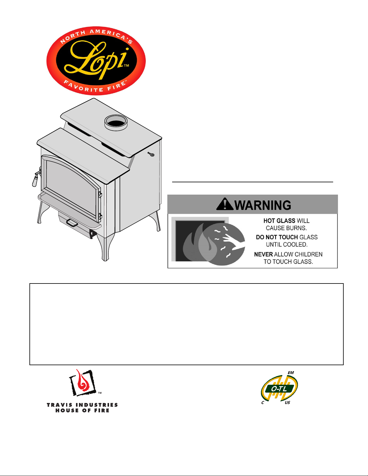
Liberty
NexGen™
Wood Stove
(EPA 2020 Compliant)
Manual
Freestanding Stove
Mobile-Home Approved
Alcove Approved
Hearth-Stove Approved
Save these instructions for future reference
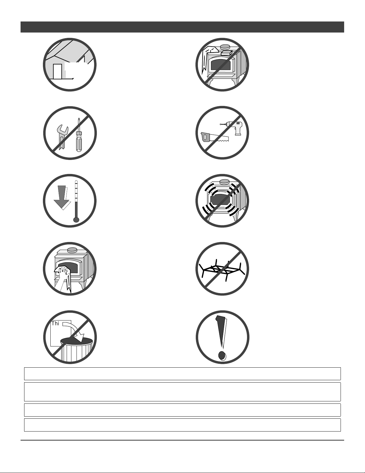
SAFETY NOTICE:
If this appliance is not properly installed, a house fire may result.
For your safety, follow the installation directions. Contact local
building or fire officials about restrictions and installation
inspection requirements in your area.
Copyright 2019, T.I.
12521 Harbour Reach Drive
Mukilteo, WA 98275
$10.00 100-01511
7/22/2020
Report #0028WS065S & 0028WS065E
Conforms to UL STD 1482-11 (R2015)
Certified to ULC S627-00
2 Introduction
Introduction
We welcome you as a new owner of a Lopi Liberty wood-burning stove. In purchasing a Lopi Liberty you
have joined the growing ranks of concerned individuals whose selection of an energy system reflects both
a concern for the environment and aesthetics. The Lopi Liberty is one of the finest appliances the world
over. This manual will explain the installation, operation, and maintenance of this appliance. Please
familiarize yourself with the Owner's Manual before operating your appliance and save the manual for
future reference. Included are helpful hints and suggestions which will make the installation and
operation of your new appliance an easier and more enjoyable experience. We offer our continual
support and guidance to help you achieve the maximum benefit and enjoyment from your appliance.
Important Information
No other Lopi Liberty appliance has the same serial
number as yours. The serial number is on the label
located on the back of the appliance.
This serial number will be needed in case you require
service of any type.
Model: Lopi Liberty
Serial Number:
Purchase Date:
Purchased From:
Register your warranty online at:
Save Your Bill of Sale.
To receive full warranty coverage, you will need to
show evidence of the date you purchased your heater.
We suggest that you attach your Bill of Sale to this
page so that you will have all the information you need
in one place should the need for service or information
occur.
traviswarranty.com
© Travis Industries 7/14/2020 - 1511 Liberty
Safety Precautions 3
Introduction ...................................................... 2
Important Information ...................................... 2
Installation Options .......................................... 6
Features ............................................................ 6
Heating Specifications ..................................... 6
Dimensions ....................................................... 6
Emissions ......................................................... 6
Planning The Installation ................................. 7
Preparation for Installation ............................. 7
Stove Installation Considerations .................. 7
Packing List ...................................................... 8
Floor Protection Requirements ...................... 8
Stove Placement Requirements ..................... 8
Clearances – Single Wall Connector .............. 9
Clearances – Reduced Clearance Connector10
Chimney Connector Requirements .............. 11
Chimney Requirements ................................. 12
Chimney Termination Requirements ........... 13
Outside Air Requirements ............................. 13
Alcove Installation Requirements ................ 14
Mobile Home Requirements .......................... 15
Standard Ceiling with a Factory Built Chimney ... 16
Cathedral Ceiling with a Factory Built Chimney .. 16
Exterior Factory Built Chimney ............................ 17
Hearth Stove Positive Connection ...................... 17
Interior or Exterior Masonry Chimney ................. 18
Safety Notice .................................................. 19
Before Your First Fire .................................... 19
Verify the Installation ........................................... 19
Curing the Paint .................................................. 19
Carbon Monoxide (CO) Emissions ...................... 19
Over-Firing the Stove .......................................... 19
Opening the Door ........................................... 20
Bypass Operation .......................................... 20
Before Starting a Fire ..................................... 21
Adjusting the Burn Rate ................................ 22
Approximate Air Control Settings ........................ 22
Understanding Your Heater’s Combustion
System ............................................................ 23
Burning Your Heater ...................................... 24
Ash Removal .................................................. 25
Ash Pan Removal ............................................... 25
Optional Blower Operation ........................... 26
Re-Loading the Stove .................................... 26
Overnight Burn ............................................... 26
Normal Operating Sounds ............................ 26
Hints for Burning ........................................... 27
Selecting Wood .............................................. 27
Why Dry Wood is Key ......................................... 27
Wood Cutting and Storage .................................. 27
Do Not Burn List ............................................ 28
Troubleshooting ............................................. 29
Daily Maintenance (while stove is in use) ... 30
Remove Ash (if necessary) ................................. 30
Clean the Glass (if necessary) ............................ 30
Monthly Maintenance (while appliance is in
use) .................................................................. 31
Door and Glass Inspection .................................. 31
Door Adjustment ................................................. 31
Creosote - Formation and Need for Removal ..... 32
Yearly Maintenance ....................................... 32
Touch-Up Paint ................................................... 32
Firebrick and Baffle Inspection ............................ 32
Door Parts ....................................................... 33
Replacing the Glass ............................................ 33
Replacing the Door Gasket ................................. 33
Replacing the Door Handle ................................. 33
Firebox Parts .................................................. 34
Floor and Side Firebrick Removal &
Replacement ................................................... 34
Air Tube Removal & Replacement ............... 35
Air Tube Identification ................................... 36
Baffle Removal & Replacement .................... 36
Removal .............................................................. 37
Replacement ....................................................... 39
Listing Label ................................................... 41
© Travis Industries 7/14/2020 - 1511 Liberty
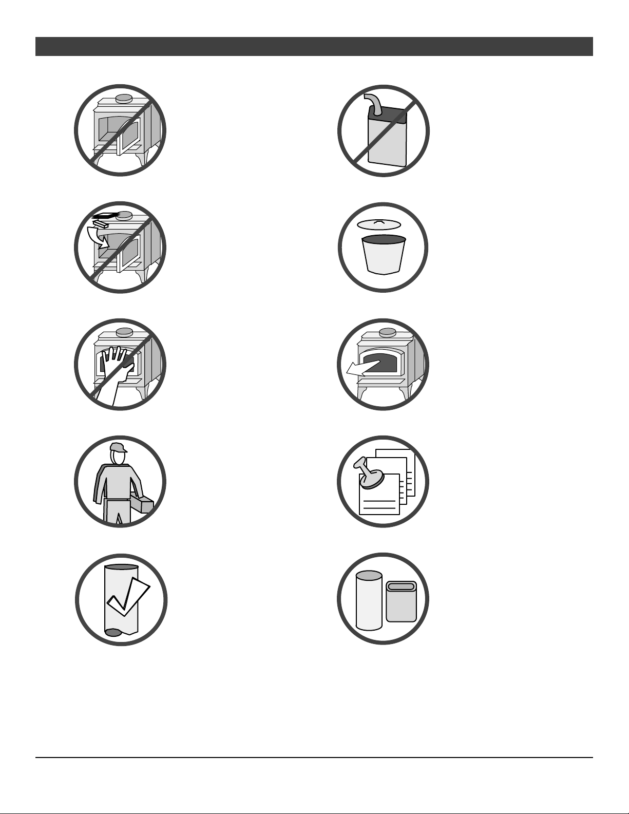
4 Safety Precautions
The viewing door must be
closed and latched during
operation.
Smoke from this appliance may
active a smoke detector when
the door is open.
Never block free airflow through
the air vents on this appliance.
Gas
Gasoline or other flammable
liquids must never be used to
start the fire or "Freshen Up" the
fire. Do not store or use
gasoline or other flammable
liquids in the vicinity of this
appliance.
This appliance is designed and
approved for the burning of cord
wood only. Do not attempt to
burn any other type of fuel other
than cord wood in this
appliance, it will void all
warranties and safety listings.
Do not touch the appliance while
it is hot and educate all children
of the danger of a hightemperature appliance. Young
children should be supervised
when they are in the same room
as the appliance.
This appliance must be properly
installed to prevent the
possibility of a house fire. The
instructions must be strictly
adhered to. Do not use
makeshift methods or
compromise in the installation.
36"
ASHES
Ok
Ashes must be disposed in a
metal container with a tight lid
and placed on a noncombustible surface well away
from the home or structure.
Keep furniture, drapes, curtains,
wood, paper, and other
combustibles a minimum of 36"
away from the front of the
appliance.
Contact your local building
officials to obtain a permit and
information on any installation
restrictions or inspection
requirements in your area.
Notify your insurance company
of this appliance as well.
Inspect the chimney connector
and chimney at least twice
monthly and clean if necessary.
Creosote may build up and
cause a house fire.
Do not connect this appliance to
any chimney serving another
appliance.
Type
HT
Clay
Liner
This appliance must be
connected to a listed high
temperature (UL 103 HT)
residential type chimney or an
approved masonry chimney with
a standard clay tile, or stainless
steel liner.
© Travis Industries 7/14/2020 - 1511 Liberty
Safety Precautions 5
Mobile
Home
When installed in a mobile
home, this appliance must be
bolted to the floor, have outside
air, and not be installed in the
bedroom (Per H.U.D.
requirements). Check with local
building officials.
Never try to repair or replace
any part of this appliance unless
instructions are given in this
manual. All other work must be
done by a trained technician.
Do not make any changes or
modifications to an existing
masonry fireplace or chimney to
install this appliance.
Allow the appliance to cool
before carrying out any
maintenance or cleaning.
Do not place clothing or other
flammable items on or near this
appliance.
This wood heater has a
manufacturer-set minimum low
burn rate that must not be
altered. It is against federal
regulations to alter this setting or
otherwise operate this wood
heater in a manner inconsistent
with operating instructions in this
manual.
Over-firing the appliance may
cause a house fire. If a unit or
chimney connector glows, you
are over-firing.
Maintain the door and glass seal
and keep them in good
condition.
Do not operate this heater with
Do not use a grate or other
device to elevate the fire off of
the firebox floor. Burn the fire
directly on the bricks.
broken or missing glass.
Avoid placing wood against the
glass when loading. Do not
slam the door or strike the glass.
This
Manual
Do not throw this manual away.
This manual has important
operating and maintenance
instructions that you will need at
a later time. Always follow the
instructions in this manual.
Travis Industries, Inc. grants
no warranty, implied or
stated, for the installation or
maintenance of your
appliance, and assumes no
responsibility of any
consequential damage(s).
Smoke and CO Detectors: Make sure your home has a working smoke detector, especially near any bedrooms. We recommend
having a smoke and/or CO detector in the same room as the wood heater for additional safety.
Proposition 65 Warning: Fuels used in gas, woodburning or oil fired appliances, and the products of combustion of such fuels,
contain chemicals known to the State of California to cause cancer, birth defects and other reproductive harm.
California Health & Safety Code Sec. 25249.6
Travis Wood Burning Fireplaces, Stoves and Inserts are protected by one or more of the following patents; U.S. 9,170,025
4,665,889 as well as other U.S. and Foreign Patents pending.
This wood heater needs periodic inspection and repair for proper operation. It is against federal regulations to operate this
wood heater in a manner inconsistent with operating instructions in this manual.
© Travis Industries 7/14/2020 - 1511 Liberty
6 Features & Specifications
Installation Options
Freestanding
Freestanding in an Alcove
Freestanding in a Mobile Home
Freestanding Hearth Stove
Features
3.65 Cubic Foot Firebox Volume
Single Operating Control
Accepts Logs Up to 24" Long (610mm)
Steel Plate Construction (5/16" & 3/16") (8mm & 10mm)
Heavy Duty Refractory Firebrick
Optional High-Tech Blower
Heating Specifications
Approximate Maximum Heating Capacity (in square feet)* 1,500 to 2,500
EPA Tested Cord Wood BTUs per Hour** 15,155 to 63,239
Maximum Burn Time Up to 12 Hours
* Heating capacity will vary depending on the home's floor plan, degree of insulation, and the outside temperature. It is also
affected by the quality and moisture level of the fuel.
** EPA tests to determine BTU output are achieved with a single load of wood at each burn rate. At home, you are likely to add
more wood to your stove to maintain your desired comfort level. By the simple process of loading your stove with additional
wood, you could achieve up to a 20% higher heat output than established during EPA testing.
This model was tested for efficiency using method B415.1-10 and was determined to have a weighted average Higher Heating
Value (HHV) Overall Heating Efficiency (OHE) of 69.5%. Overall efficiency of the heater may be lower if the heater is
operated without a heat exchange blower or with the installed heat exchange blower turned off.
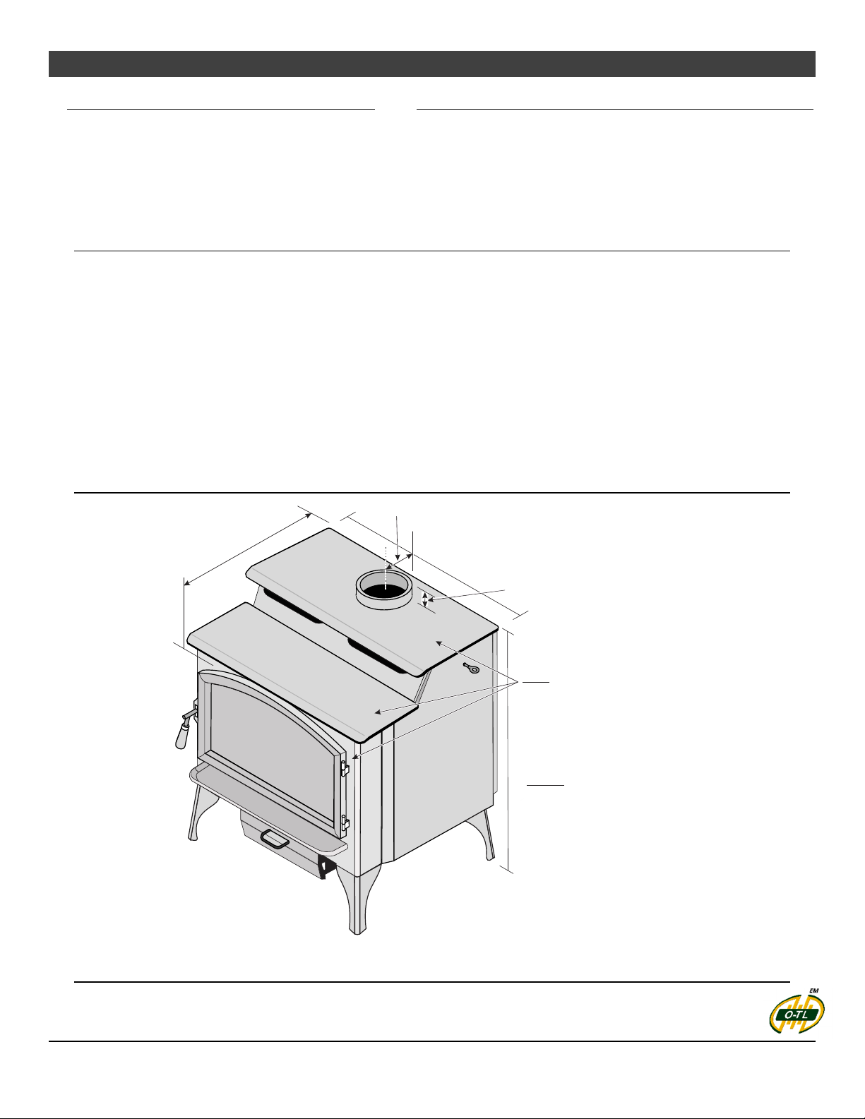
Dimensions
(
1
5
2
m
6-1/4” (159mm)
3
m
)
D
i
a
.
0
”
(
7
6
2
m
m
)
2-3/16” (56mm)
)
m
m
1
2
6
(
”
6
1
/
7
-
4
2
6
”
Note:
Measure side, corner, and back
clearances from the stove top.
Measure front clearances from
the stove face
Height:
34-3/16” (869mm)
Weight:
570 lbs. (259 Kg.)
IDB1010
Figure 1
Emissions
This heater meets the 2020 U.S. EPA’s cord wood emission limits for wood heaters. Tested to EPA Alt-125,
ASTM E3053-17, ASTM 2515-11, CSA B415.1-10 this heater has been shown to deliver heat at rates
ranging from 15,155 to 63,239 BTU/hr and an emission value of 2.5g/h. Report No. 0028WS062E
© Travis Industries 7/14/2020 - 1511 Liberty
Stove Installation (for qualified installers only) 7
SAFETY NOTICE:
Please read this entire manual before you install and use your new room heater. Failure to
follow instructions may result in property damage, bodily injury, or even death. Contact
local building or fire officials about restrictions and installation inspection requirements in
your area.
Planning The Installation
We suggest that you have an authorized Travis Industries dealer install your stove. If you install the
stove yourself, your authorized dealer should review your installation plans.
Check with local building officials for any permits required for installation of this stove and notify your
insurance company before proceeding with installation.
The location of your wood heater in your home will decide how affectively the heat produced will spread
throughout your house. Attention to the home design with consideration of natural convection and air
circulation should be taken into account when choosing the placement of your heater within the home.
Preparation for Installation
Check for damage to the exterior of the stove (dents should be reported, scratches can be fixed by
applying touch-up paint).
Check the interior of the firebox (replace cracked firebrick and make sure baffle is in place).
The stove can be lightened by removing the firebricks and baffle (page 33) - replace before operation.
Stove Installation Considerations
The table below details the six most common types of installations and the considerations for each type.
Alternative methods of installation are available if they comply with local building codes.
Installation Type Considerations
Standard Ceiling with a Factory Built Chimney
(Page 16)
Cathedral Ceiling with a Factory Built Chimney
(Page 16)
Exterior Factory Built Chimney
(Page 17)
Hearth Stove Positive Connection
(Page 17)
Interior Masonry Chimney
(Page 18)
Requires ceiling and roof penetration
Provides best draft
Cathedral style chimney support required
Provides best draft
Uses two elbows to route chimney outside
Exterior chimney is hidden from the room
Elbows reduce draft
Optional exterior chase reduces cold air blockage
Utilizes existing masonry or zero clearance (metal)
chimney
Provides good draft due to full reline
Easier to clean than direct or horizontal hearth stove
Utilizes existing masonry chimney (not approved for
zero clearance (metal) fireplaces)
© Travis Industries 7/14/2020 - 1511 Liberty
8 Stove Installation (for qualified installers only)
Packing List
Wood Moisture Meter
Touch up paint
Bypass Tool
Gloves
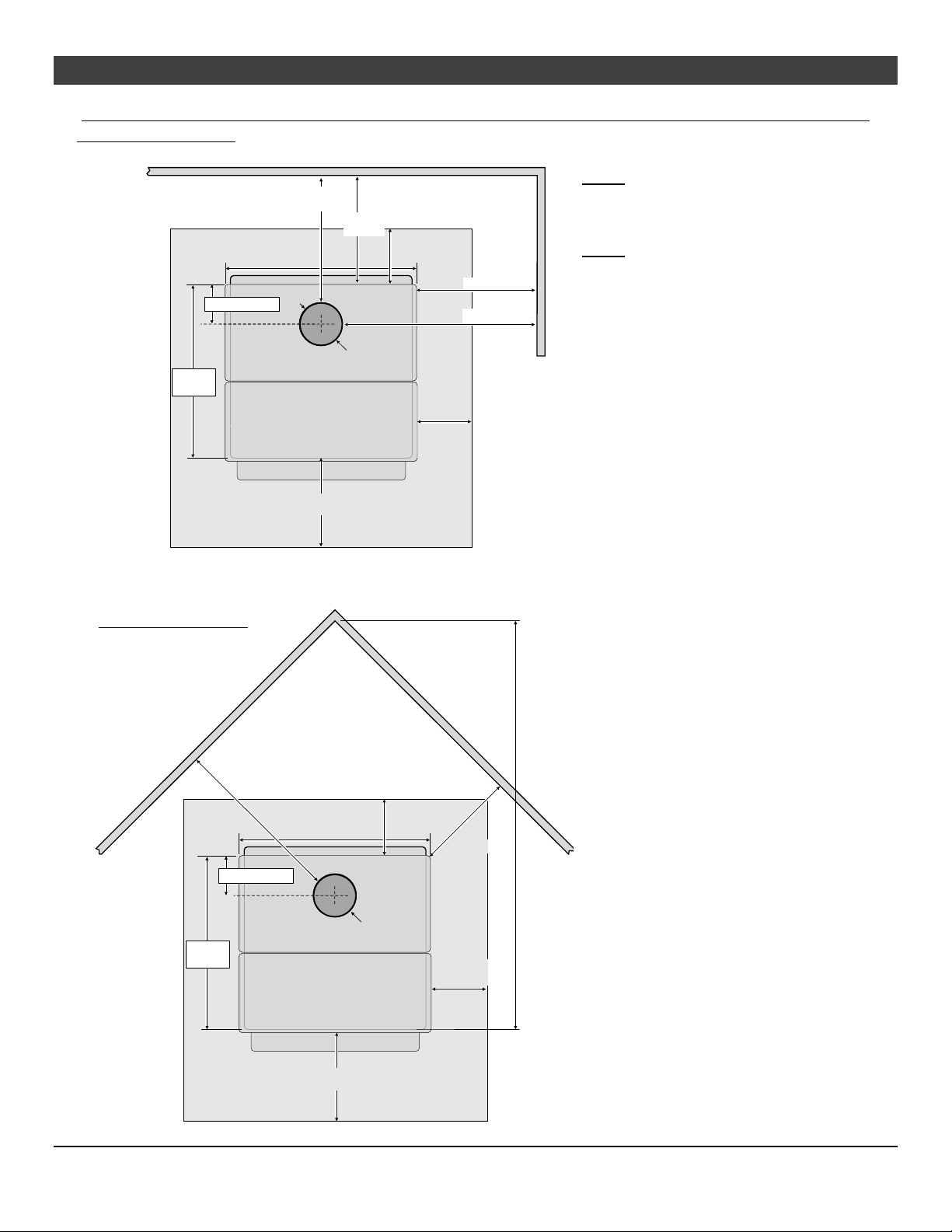
Floor Protection Requirements
Stove must be placed on the Travis Industries legs.
Floor protection must extend to the sides, rear, and front of the stove (see “Clearances” below for
minimum floor protection).
Floor protection must be non-combustible and at least .018" thick (26 gauge).
No R value is required for floor protection - (R = 0).
Stove Placement Requirements
Clearances may be reduced by methods specified in NFPA 211, listed wall shields, pipe shields, or
other means approved by local building or fire officials.
Stove must be placed so that no combustibles are within, or can swing within (e.g. drapes, doors), 36"
(914mm) of the front of the stove
If the stove is placed in a location where the ceiling height is less than 7' (2134mm), it must follow the
requirements in the section "Alcove Installation Requirements"
Must maintain the clearances to combustibles listed below (drywall, furniture, etc.):
The stove requires an air source to operate. Combustion air starvation will result in poor performance
or smoke in the house.
© Travis Industries 7/14/2020 - 1511 Liberty
Stove Installation (for qualified installers only) 9
STRAIGHT INST
ALLA
TIONS
Clearances – Single Wall Connector
(singlewall connector)
24-7/16”
(621mm)
30” (762mm)
6-1/4” (159mm)
TOP OF ST OVE
18-1/4”
(464mm)
15”
(381mm)
Connector
App. 6" (153mm) dia.
US 16" (407mm)
Can. 18" (458mm)
FLOOR PR OTECTION
US 6" (153mm)
Can. 8" (204mm)
16" (407mm)
28" (712mm)
US 6" (153mm)
Can. 8" (204mm)
NOTE: Measure rear and side
stove clearances from the nearest
edge of the stove top.
NOTE: Measure front floor
protection from the face of the
stove (unibody).
CORNER INSTALL ATIONS
(singlewall connector)
21" (534mm)
6-1/4” (159mm)
24-7/16”
(621mm)
30” (762mm)
App. 6" (153mm) dia.
TOP OF STOVE
Approx. 52-7/8" (1343mm)
from Corner to Front of Stove
US 6" (153mm)
Can. 8" (204mm)
Connector
IDB1233
9-1/2" (242mm)
US 6" (153mm)
Can. 8" (204mm)
US 16" (407mm)
Can. 18" (458mm)
FLOOR PROTECTION
© Travis Industries 7/14/2020 - 1511 Liberty
10 Stove Installation (for qualified installers only)
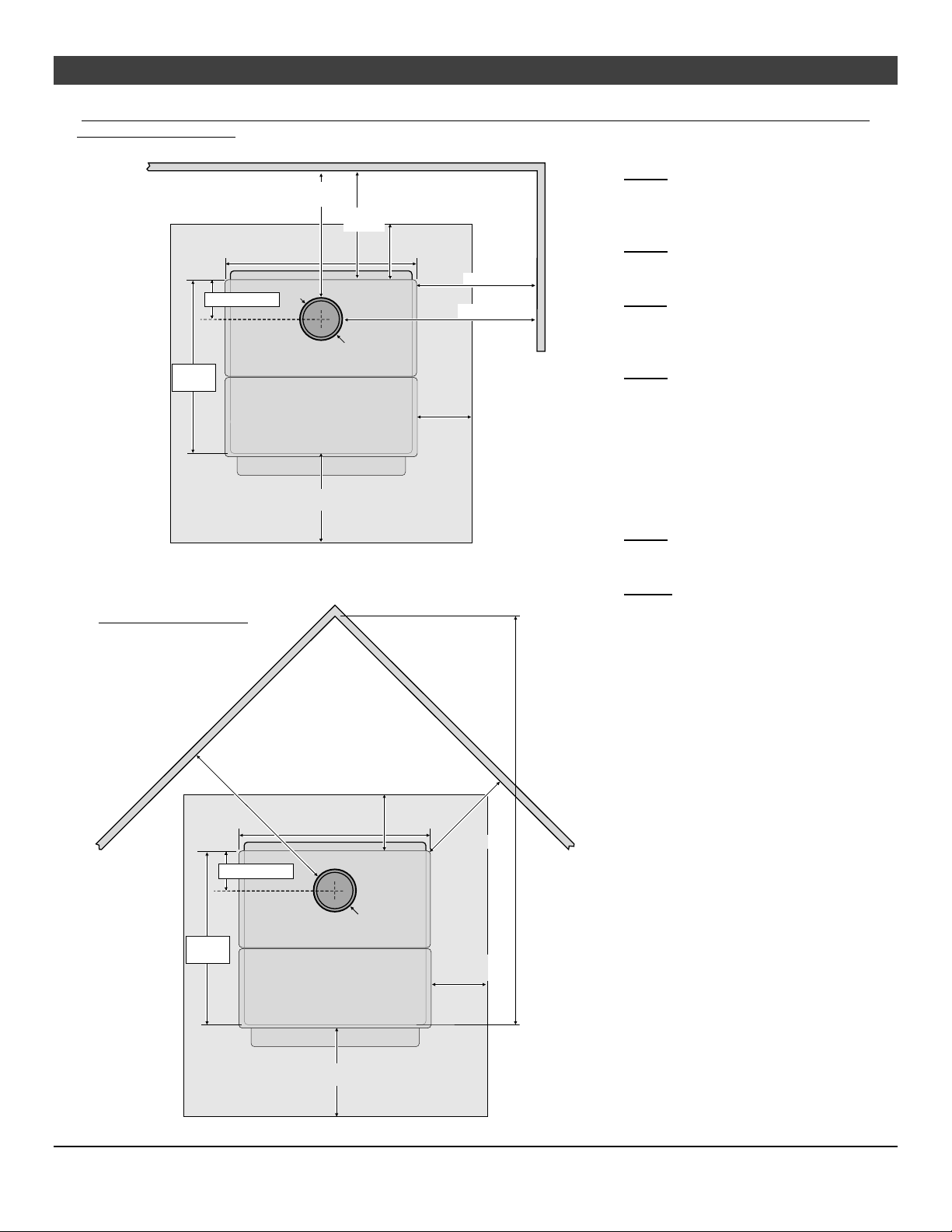
STRAIGHT INST
ALLA
TIONS
Clearances – Reduced Clearance Connector
(double wall connector)
24-7/16”
(621mm)
30” (762mm)
6-1/4” (159mm)
TOP OF ST OVE
12-3/4”
(324mm)
10”
(255mm)
Connector
App. 7" (178mm) dia.
US 16" (407mm)
Can. 18" (458mm)
FLOOR PR OTECTION
US 6" (153mm)
Can. 8" (204mm)
16" (407mm)
27-1/2" (699mm)
US 6" (153mm)
Can. 8" (204mm)
NOTE: Measure rear and side stove
clearances from the nearest edge of the
stove top.
NOTE: Measure front floor protection
from the face of the stove (unibody).
NOTE: Reduced clearance connectors
may require an appliance adapter to
connect to the flue collar.
NOTE: Standard residential installations
with reduced clearance connector may
use the clearance determined by the
manufacturer of the connector for the
connector to wall clearance or the
clearance listed in this manual. Offsets
must be used to maintain the stove to
wall clearance.
NOTE: Vent diameter varies depending
upon brand and model.
CORNER INSTALL ATIONS
(double wall connector)
18-1/2" (471mm)
6-1/4” (159mm)
24-7/16”
(621mm)
30” (762mm)
App. 7" (178mm) dia.
TOP OF STOVE
Approx. 51" (1296mm)
from Corner to Front of Stove
US 6" (153mm)
Can. 8" (204mm)
Connector
IDB1236
7-1/2" (191mm)
US 6" (153mm)
Can. 8" (204mm)
NOTE: Reduced clearance installations
require one of the chimneys and
connectors listed below:
AMERI-TEC model DCC with model HS
chimney
DURAVENT model DVL with DURATEC or
DURA-PLUS chimney
GSW Super Chimney Twenty-One
connected directly to appliance
I.C.C. Excel (2100-2 Can.) (103-HT USA)
chimney with ULTRABlack connector
METALFAB model DW connector with TG
chimney
OLIVER MACLEOD PROVENT model PV
connector with model 3103 chimney
SECURITY model DP connector with
SECURITY model ASHT or S2100 chimney
SELKIRK METALBESTOS model DS
connector with model SSII chimney
Standard Masonry Chimney with any one of
the above listed connectors
US 16" (407mm)
Can. 18" (458mm)
FLOOR PROTECTION
© Travis Industries 7/14/2020 - 1511 Liberty
Stove Installation (for qualified installers only) 11
Chimney Connector Requirements
Chimney connector is required from the flue collar of the stove to the factory-built chimney or
masonry chimney.
The chimney connector must be 6” diameter and a minimum 24 gauge black steel, or one of the
reduced-clearance connectors listed on page 8.
NOTE: Aluminum or galvanized steel is not allowed – these materials cannot withstand the flue
temperatures and may give off toxic fumes when heated.
NOTE: Standard residential installations may use single-wall connector (Mobile-Homes may not).
The chimney connector may not pass through a ceiling, attic, roof, closet, or any other concealed
space (use listed UL 103 HT chimney – see “Chimney Requirements” for details). DO NOT USE
CONNECTOR PIPE AS CHIMNEY.
IN CANADA: Where passage through a wall or partition of combustible construction is desired, the
installation shall conform to CAN/CSA-B365, Installation Code for Solid-Fuel-Burning Appliances and
Equipment.
o
The chimney connector should be as short and direct as possible. No more than 180
o
90
elbows, or two 45o & one 90o elbow, etc.) may be used for the entire system (connector and
chimney).. Horizontal runs should slope upwards 1/4” per foot and be a maximum 36” long.
The chimney connector must be installed with the crimped end pointing downwards. This prevents
creosote from leaking to the exterior of the pipe.
of elbows (two
IDB1117
The chimney connector must be fastened to the stove and each adjoining section (and chimney).
Standard residential installations may use single-wall connector (Mobile-Homes may not).
Standard residential installations with reduced clearance connector may use the clearance
determined by the manufacturer of the connector for the connector to wall clearance or the clearance
listed in this manual. Offsets must be used to maintain the stove to wall clearance. Mobile homes
must use the clearances listed in this manual under "Additional Requirements for Mobile Home
Installations".
Chimney connector must be in good condition and kept clean.
© Travis Industries 7/14/2020 - 1511 Liberty
12 Stove Installation (for qualified installers only)
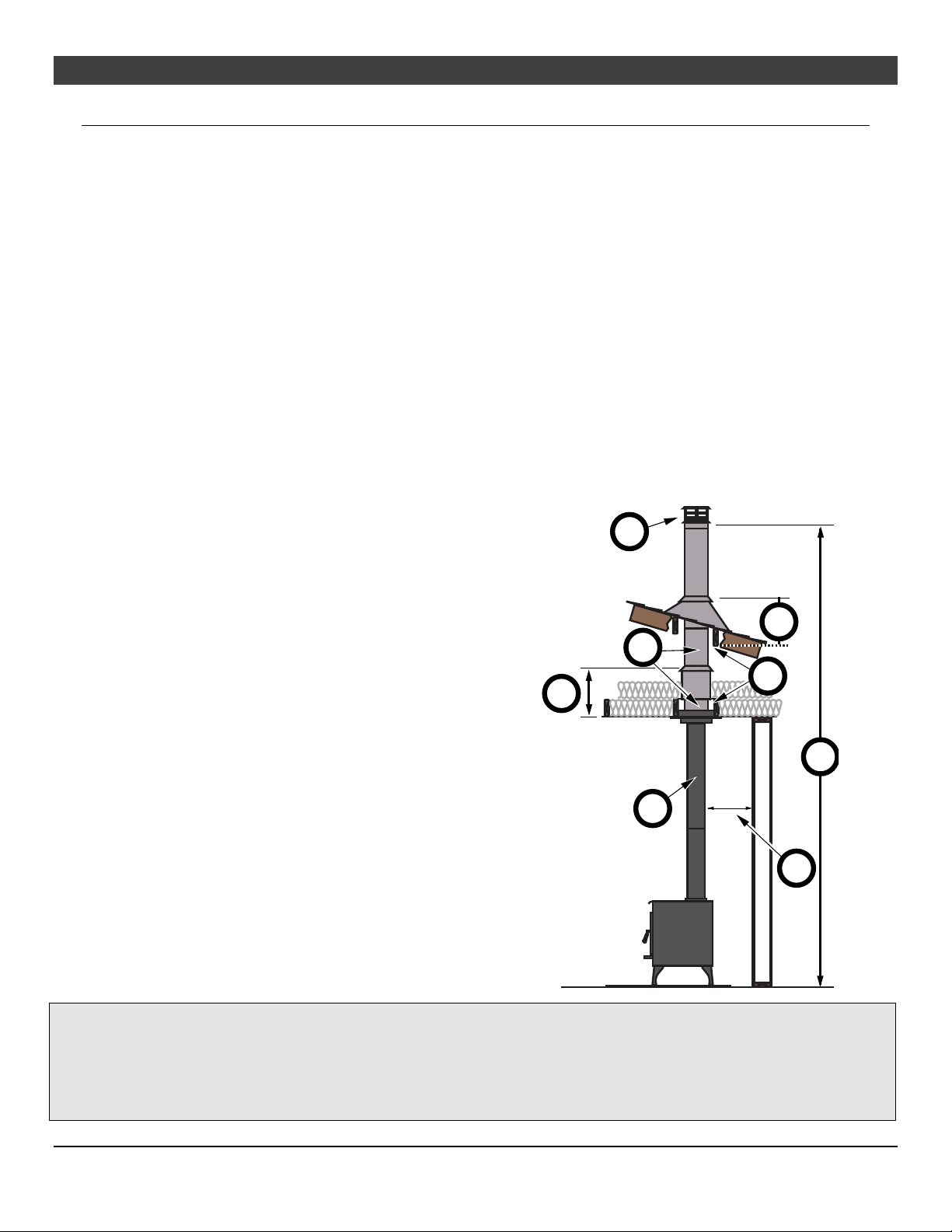
Chimney Requirements
DO NOT CONNECT THIS UNIT TO A CHIMNEY FLUE SERVING ANOTHER APPLIANCE.
DO NOT CONNECT TO OR USE IN CONJUNCTION WITH ANY AIR DISTRIBUTION DUCTWORK
UNLESS SPECIFICALLY APPROVED FOR SUCH INSTALLATIONS
IN CANADA: This appliance must be connected to a factory-built chimney conforming to CAN/ULC-
S629, Standard for 650°C Factory-Built Chimneys.
UL 103 HT Chimney must be used from the first ceiling or floor or wall penetration to the chimney
cap.
Use 6" diameter type UL 103 HT chimney from one manufacturer (do not mix brands) or code
approved masonry chimney with a flue liner.
Chimney connector and chimney must be fastened to the stove and each adjoining section.
Follow the chimney manufacturer's clearances and requirements.
Use the chimney manufacturer's fire stops, attic guards, roof supports, and flashings when passing
through a ceiling or thimble when passing through a combustible wall.
o
No more than 180
NOTE: Additional elbows may be allowed if draft is sufficient. Whenever elbows are used the draft is
adversely affected. Additional chimney height may be required to boost draft.
of elbows (two 90o elbows, or two 45o & one 90o elbow, etc.).
b
Drafting
Performance
(a) M in. Syst em Height 15’
M ax. S ystem Height 33’
(b) Roof P enetration and Termination
(See Chimney M anufacturer’s Req. )
(c) Chimney Sections
(d) Ceiling Penetration
(See Chimney M anufacturer’s Req. )
c
d
b
e
a
(e) M in. air space to combustibles
(See Chimney M anufacturer’s Req. - Typ 2”)
(f) Connector - see “Chimney Connector” on the
previous page
f
f
ID B1118
Figure 2
Draft is the force which moves air from the appliance up through the chimney. The amount of draft in
your chimney depends on the length of the chimney, local geography, nearby obstructions and other
factors. Too much draft may cause excessive temperatures in the appliance and may damage the
heater. Inadequate draft may cause backpuffing into the room and `plugging' of the chimney.
Inadequate draft will cause the appliance to leak smoke into the room through appliance and chimney
connector joints. An uncontrollable burn or excessive temperature indicates excessive draft.
© Travis Industries 7/14/2020 - 1511 Liberty
Stove Installation (for qualified installers only) 13
y
.
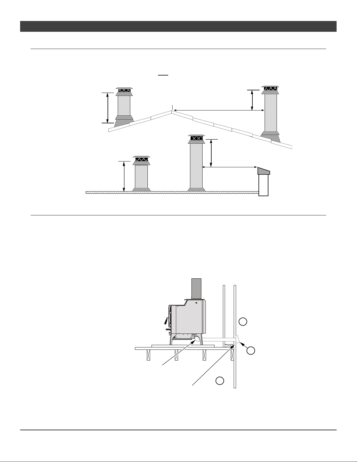
Chimney Termination Requirements
Must have an approved cap (to prevent water from entering)
Must not be located where it will become plugged by snow or other material
Must terminate at least 3' above the roof and at least 2' above any portion of the roof within 10' (see
Figure 3).
Min. 2’ (610mm)
Min. 3’ (914mm)
Min. 3’ (914mm)
10’ (3.04M)
Min. 2’ (610mm)
10’ (3.04M)
IDB1119
Figure 3
Outside Air Requirements
Required for mobile homes & in certain localities (check with building officials).
Must not be drawn from an enclosed space (garage, unventilated crawl space). May be drawn from
ventilated crawl space (a) or exterior of home (b). Must have suitable rodent/debris screen and rain
protection (hood) (c).
Requires the optional outside air kit (sku 99200139).
Air duct maximum length is 15’ (4.57M) with a minimum cross section of 16 square inches
(10322mm²) or 6’ (1.82M) with a minimum cross section of 7 square inches (4517mm²).
IDB1206
b
c
Out side Air
Connector
Outside air entranc e must be placed so
it does not become blocked b
snow
a
Figure 4
© Travis Industries 7/14/2020 - 1511 Liberty

14 Stove Installation (for qualified installers only)
Alcove Installation Requirements
Whenever the stove is placed in a location where the ceiling height is less than 7' (2134mm) tall, it is
considered an alcove installation. Because of the reduced height, the special installation requirements
listed below must be met.
Chimney connector and chimney must be one of the following types:
AMERI-TEC model DCC with model HS chimney
DURAVENT model DVL with DURATEC or DURA-PLUS chimney
GSW Super Chimney Twenty-One connected directly to appliance
I.C.C. Excel (2100-2 Can.) (103-HT USA) chimney with ULTRABlack connector
METALFAB model DW connector with TG chimney
OLIVER MACLEOD PROVENT model PV connector with model 3103 chimney
SECURITY model DP connector with SECURITY model ASHT or S2100 chimney
SELKIRK METALBESTOS model DS connector with model SSII chimney
Standard Masonry Chimney with any one of the above listed connectors
NOTE: Reduced clearance connectors may not connect to the flue collar – an appliance adapter may be required.
Alcoves are classified as combustible or non-combustible. Non-combustible alcoves must have walls
and a ceiling that are 3 1/2" (89mm) thick of a non-combustible material (brick, stone, or concrete.
This non-combustible material must be spaced and ventilated at least 1" (25mm) off of all combustible
materials (walls, ceiling, etc.) to allow air to move around the non-combustible walls and ceiling. All
other alcoves are considered combustible. The clearances below must be met:
Miniumum Clearance Combusti ble
(a) Sidewal l to stove 16”
(b) Backwall to stove 10”
(c) Connector to
sidewal l
(d) Connector to
backwall
(e) Maximum depth of
alcove
(f) Minimum width of
alcove
(g) Minimum height of
alcove
Alcove
(407mm)
(254mm)
27-1/2”
(699mm)
12-3/4”
(324mm)
48”
(1220mm)
62”
(1575mm)
84”
(2134mm)
Non-Combustible
Alcove
6”
(153mm)
2”
(51mm)
17-1/2”
(445mm)
4-3/4”
(121mm)
48”
(1220mm)
42”
(1067mm)
6”
(153mm)
above stove top
Non-combustible alcove
construction (on walls
and ceiling) - see the
explanation above.
Ventilated
air space
Min. 3 1/2"
(89mm)
combustible
material
1" (25mm)
Min.
non-
c
Combustible
materials
d
a
b
g
IDB1121
Non-combustible
reinforcer
f
e
IDB1235
© Travis Industries 7/14/2020 - 1511 Liberty

Stove Installation (for qualified installers only) 15
Mobile Home Requirements
Outside air must be installed - see "Outside Air Requirements" on page 13
Chimney connector and chimney must be one of the following types:
AMERI-TEC model DCC with model HS chimney
DURAVENT model DVL with DURATEC or DURA-PLUS chimney
I.C.C. Excel (2100-2 Can.) (103-HT USA) chimney with ULTRABlack connector
METALFAB model DW connector with TG chimney
SECURITY model DP connector with SECURITY model ASHT or S2100 chimney
Standard Masonry Chimney with any one of the above listed connectors
NOTE: Reduced clearance connectors may not connect to the flue collar – an appliance adapter may be required.
Stove placement must maintain the following clearances to combustibles (drywall, furniture, etc.)
Straight Installations Corner Installations
27-1/2”
(699mm)
16”
(407mm)
12-3/4”
(324mm)
10”
(255mm)
18-1/2”
(471mm)
If using offsets, use the connector clearance listed in Figure 6, not
the connector manufacturer's clearance.
The appliance must be secured to the floor (consult your building
official). The leg clips used to secure the stove to the shipping
pallet may be used to secure the stove to the floor of the mobile
home.
Mobile home installations require a spark arrester at the chimney
termination. Follow the chimney manufactures instructions for
maintaining a proper moisture barrier at the chimney penetration.
The appliance must be grounded to the chassis of the mobile
home (consult your building official).
WARNING: DO NOT INSTALL IN SLEEPING ROOM.
CAUTION: THE STRUCTURAL INTEGRITY OF THE MOBILE HOME
FLOOR, WALL, AND CEILING/ROOF MUST BE MAINTAINED.
7-1/2”
(191mm)
45°
IDB1237
Figure 5
12” Min.
Connector Clearance
(as outlined above)
Stove Clearance
(as outlined above)
IDB 1166
Figure 6
© Travis Industries 7/14/2020 - 1511 Liberty

16 Stove Installation (for qualified installers only)
.
Standard Ceiling
with a Factory
Built Chimney
Chimney Cap
(See the sect ion "Chimney
Termination Requirements"
for more details)
Chimney Pipe Sections
Insulation
Follow the chimney
manufacturer's instructions
and clearances for floor
penetrations. A ceiling
support is required, an attic
insulation shield is required
where insulat ion is present
Connector Pipe Sections
Floor Protec tion
(See the sect ion "Floor
Protection Requirements"
for more details)
Follow the chimney
manufacturer's instructions
and clearances for roof
penetrations. A storm collar
and flashing are required
(some require a radiation
shield).
Minimum Air Space t o
Combustibles (See
Chimney Manufacturer's
Instructions - usually 2" (51mm))
Minimum 15'
(4.57M)
Maximum 33'
(10.06M)
Stove Clearances
(See the section "St ove
Placement Requirements"
for more details)
Cathedral Ceiling
with a Factory
Built Chimney
Chimney Cap
(See the section "Chimney
Termination Requirements"
for more details)
Chimney Pipe Sections
Minimum Air Space to
Combustibles (See
Chimney Manuf act urer's
Instructions - usually 2" (51mm))
Connector Pipe Sections
Floor Protection
(See the section "Floor
Protection Requirements"
for more details)
IDB1122
Follow the chimney
manufacturer's instructions
and clearances for roof
penetrations. A storm collar
and flashing are required
(some require a radiation
shield).
Stov e Clearances
(See the section "St ove
Placement Requirement s"
for more details)
Figure 7
Minimum 15'
(4.57M)
Maximum 33'
(10.06M)
IDB1123
© Travis Industries 7/14/2020 - 1511 Liberty
Figure 8

Stove Installation (for qualified installers only) 17
Foll
m
c
a
c
3
.
5
ow the chimney
Exterior Factory
Built Chimney
NOTE:
Exterior chimneys are
subject to greater
moisture and creosote
accumulation due to the
lower temperatures. An
insulated chase will
reduce these
accumulations (the
proper clearances to the
chimney must be
maintained).
Hearth Stove
Positive
Connection
NOTE:
Most factory-built
chimney manufacturers
make stainless steel
chimney liners, either
flexible or rigid. This
provides a wide variety
of installation options.
Make sure to follow the
manufacturer's
instructions for
installation and support.
Chimney Cap
(See the section "Chimney
Termination Requirements"
for more details)
Chimney Pipe Sections
Minimum Air Space t o
Combustibles (See
Chimney Manufacturer's
Ins tructions - usually 2" (51mm))
Connector must maint ain
Proper Clearance to Ceiling
Min 18” (457mm) for
single-wall pipe
Connect or Pipe Sections
Floor Protect ion
(See the section "Floor
Protection Requirement s"
for more details)
NOTE: The entire fireplace and
himney must be clean, undamaged,
nd meet all local building codes
(UBC, etc.). Damage must be
repaired prior to installation. The
himney must be 15' (4.57M) to
3' (10.05M) tall
Wall Bands
and
Supports
Minimum 15' (4.57M)
Maximum 33' (10.05M)
Stove Clearances
(See the section "St ove
Placement Requirements"
for more details)
Cap and flashing
prevents water from
entering
The liner must be
stainless steel connector
or flexible vent. Follow
the liner manufacturer's
instructions for installation
and support.
manufact urer's
instructions and
clearances f or roof
penetrations. A stor
collar and flashing are
required (some
require a radiation
shield).
Optional
insulated
chase
Insulated Tee
(with cleanout )
Follow the chimney
manufact urer's
instructions and
clearances for wall
penetrations. A
wall radiation shield
(thimble) is
required.
IDB1124
Figure 9
Combustible
Mantle
Floor Protection
(See the section
"Floor Protection
Requirements"
for more details)
Min. 36"
(915mm)
Remove damper
or wire it open
See the section
"Stove Placement
Requirements" for
minimum clearances
required.
IDB112
Figure 10
© Travis Industries 7/14/2020 - 1511 Liberty

18 Stove Installation (for qualified installers only)
s
c
c
e
a
e
NOTE: The chimney must have a
Interior or Exterior
Masonry Chimney
NOTE:
This type of installation
is not allowed in
Canada.
NOTE:
This type of installation
requires a UBC
approved masonry
connector or a factory
built (U.L. Listed) wall
thimble.
lay tile liner. If it does not, the
installation must use a positive
onnection (full reline). The
ntire fireplace and chimney must
be clean, undamaged, and meet
ll local building codes (UBC,
tc.). Damage must be repaired
prior to installation. The chimney
must be 15' (4.57M) to 33' (10.05M) tall.
Connector must maintain
Proper Clearance to Ceiling
Min 18” (457mm) for
single-wall pipe
Connector Pipe Sections
Stove Clearances
(See the section "Stove
Placement Requirements"
for more details)
Cap prevents water
from entering
Clay Liner
This type of
installation require
a UBC approved
masonry connector
or other method
approved by the
NFPA 211 standard
Floor Protection
(See the section "Floor
Protection Requirements"
for more details)
IDB1127
Make sure the
clean-out seals in
place.
Figure 11
© Travis Industries 7/14/2020 - 1511 Liberty

Operating Your Appliance 19
Safety Notice
If this appliance is not properly installed, a house fire may result. For your safety, follow the installation
directions. Contact local building or fire officials about restrictions and installation inspection
requirements in your area.
The air control may become hot during operation - use gloves or a tool to prevent burns.
Use gloves when reloading wood.
Read and follow all of the warnings on pages 4 and 5 of this manual.
Before Your First Fire
Verify the Installation
Before starting the stove, verify that the stove is properly installed and all of the requirements in this
manual have been followed.
Keep all flammable materials 36" away from the front of the stove (drapes, furniture, clothing, etc.).
Curing the Paint
Follow the steps below to cure the paint (first fire):
a) Open doors and windows in the room to ventilate the heater during the
curing process.
b) Vacate the room. The fumes from the initial heating process are non-toxic
but may be unpleasant.
c) Slowly bring the heater to a medium burn (400°F/204°C) for 45 minutes.
Then increase the burn temperature to a hot burn (600°F/315°C) for an
additional 45 minutes. This will cure the paint.
Door Gasket - The door gasket might adhere to the paint on the front of the
heater. Leave the door slightly ajar for the first fire and be careful when
opening the door after the first fire.
2 to 4 hours
IDB1135
Carbon Monoxide (CO) Emissions
Smoke from wood heaters contain CO. This gas is an indication of incomplete combustion and is
detrimental to the environment and to your health. The more visible the smoke, the higher the CO levels.
Burning dry wood is the most significant step you can take to reduce CO emissions. It is also important to
understand the combustion process so you can burn your heater efficiently. Read the manual thoroughly
so that you can operate your heater in the most efficient and clean manner possible.
Over-Firing the Stove
DO NOT OVERFIRE THIS HEATER: Attempts to achieve heat output rates that exceed heater design
specifications can result in permanent damage to the heater.
This stove was designed to operate at a high temperature. But due to differences in vent configuration,
fuel, and draft, this appliance can be operated at an excessive temperature. If the stove top or other area
starts to glow red, you are over-firing the stove. Shut the air control down to low and allow the stove to
cool before proceeding.
Over-firing may lead to damage of plated surfaces. If you are uncertain of over-firing conditions, we
suggest placing a stove thermometer (e.g. Rutland® Model 710) directly over the door on the stove top temperatures exceeding 800° are generally considered over-firing and will void the warranty.
© Travis Industries 7/14/2020 - 1511 Liberty

20 Operating Your Appliance
T
L
h
.
U
Opening the Door
ift the door
andle
The door becomes hot during use - use gloves or a tool to prevent burns.
Swing
the door
open.
IDB1238
Do not operate the stove with the door open. A fire hazard will result.
To prevent smoke from entering the room, open the air control before opening the door. You can also
open the door a small amount and let air enter the firebox.
Bypass Operation
he bypass control becomes hot during operation - use gloves or a tool to prevent burns.
The bypass controls the flow of smoke inside the heater. When pulled out, smoke goes directly up the
flue, creating more draft. When pushed in, the smoke goes around the baffle, utilizing the secondary
combustion and making the heater more efficient.
When starting or re-loading, pull the bypass out.
During normal operation, push the bypass in.
se the included pull tool
to operate the bypass rod
Bypass Pulled Out
Used for starting and re-loading
Bypass Pushed In
Used for normal operation
IDB1239
© Travis Industries 7/14/2020 - 1511 Liberty

Operating Your Appliance 21
T
Before Starting a Fire
he bypass control becomes hot during operation - use gloves or a tool to prevent burns.
Make sure the air control is pulled out. If additional air is needed, open the doors 1/4" during the first
five minutes of start-up.
Never use gasoline, gasoline-type lantern fuel, kerosene,
charcoal lighter fluid, or similar liquids to start or "freshen up" a
fire in this stove. Keep all such liquids well away from the stove
while it is in use.
DO NOT USE CHEMICALS OR FLUIDS TO START THE FIRE.
DO NOT BURN GARBAGE OR FLAMMABLE FLUIDS SUCH
AS GASOLINE, NAPHTHA OR ENGINE OIL. Do not place
such fuel within space heater installation clearances or within
the space required for charging and ash removal.
If using a fire-starter, use only products specifically designed for
stoves - follow the manufacturer's instructions carefully.
HOT WHILE IN OPERATION. KEEP CHILDREN, CLOTHING
AND FURNITURE AWAY. CONTACT MAY CAUSE SKIN
BURNS.
If the smoke does not pass up the chimney, ball up one sheet of
newspaper, place it in the center of the firebox and light it. This
should start the chimney drafting (this eliminates "cold air
blockage").
Use plenty of kindling to ensure the stove reaches a proper
temperature. Once the kindling is burning rapidly, place a few
larger pieces of wood onto the fire.
IDB1 240
© Travis Industries 12/16/2020 - 1511 Liberty

22 Operating Your Appliance
Adjusting the Burn Rate
Use the air control slider to control the burn rate of the stove. See the illustration below for details.
Use the air control to
change the burn rate
High Burn
(air control open)
Approximate Air Control Settings
Medium Burn 1/4" to fully open
Low Burn
(air control closed)
Overnight Burn
Fully in to 1/4" open
IDB1241
High Burn Fully open (pulled out)
The air control may become hot during operation - use gloves or a tool to prevent burns.
The air control may take several minutes to influence the burn rate. When making adjustments, you
may wish to let the stove burn for 10 minutes to gauge performance.
© Travis Industries 7/14/2020 - 1511 Liberty

Operating Your Appliance 23
Understanding Your Heater’s Combustion System
This heater uses a dual combustion system detailed below:
Primary Combustion: This is the combustion (fire) that takes place directly on the wood. Primary combustion
determines how fast the fire burns. Air for primary combustion is supplied through the air control. When you
adjust the air control you control the amount of air that reaches the fire and creates primary combustion. The air
control supplies air to the air wash (the air holes above the door opening – used to help clean the glass) and
through the pilot orifice (center bottom of the door opening). By using the air control, and supplying air through
these two openings, you control primary combustion.
Secondary Combustion: This is the combustion (fire) that does not contact the wood. Secondary combustion
burns the visible emissions or smoke that is not consumed during primary combustion. During some phases of
combustion you will see secondary combustion. It appears as a glowing flame at the top of the firebox. Air for
secondary combustion is supplied by the air tubes at the top of the firebox.
Items to Consider:
During medium and high burn rates the stove will manage secondary and primary combustion on its own.
When the heater is set to a low burn rate more care is needed to ensure the secondary combustion system
works properly. Make sure the stove is hot and a good coal bed is established before adjusting your heater to
low burn.
Understanding the combustion system in this heater will help minimize the visible emissions this heater
releases into the environment. The primary pilot orifice at the center bottom of the door opening is designed to
help the secondary combustion at low burn settings. The pilot provides a small amount of air that burns up
through the fuel load providing the heat and flame needed for the secondary system to ignite. The air tubes
under the baffle need to remain ignited for low burns to be effective.
As you load your heater for a low burn, take care in placing the wood. This will affect how well your
secondary system works as the wood is consumed. Do not block the pilot orifice. Stack wood so the pilot air
can burn its way up between the pieces, helping your heater burn effectively throughout the low fire. This will
reduce the visible emissions your heater produces and increase the amount of heat you get from the wood. If
you are unsure how well your heater is burning look at the chimney cap to monitor visible emissions.
© Travis Industries 7/14/2020 - 1511 Liberty

24 Operating Your Appliance
Burning Your Heater
Starting a Fire: Make sure your air control is all the way open and the by-pass (if equipped) is in the
open position. To reduce the amount of smoke when starting your fire, the “Top Down” method described
below allows for the cleanest starts. Stack four or five layers of medium-sized kindling 1 to 2” in diameter
in a tic tac toe pattern, four pieces per layer with about ½” to 1” spacing
between pieces. On top of the kindling stack, place crumpled
newspaper and a nest of pencil-sized kindling, this will produce
sustained heat at the beginning of the process to help establish draft in
the chimney.
Light the paper and small kindling on top and let it burn down through
the layers of kindling. Using this this method, the door should be able to
be closed within approximately two to three minutes after lighting the kindling. If the fire starts to die
down, reopen the door and leave it cracked open until the fire takes recovers and becomes established.
Never leave your heater unattended if the door is not latched shut. Three to five minutes after closing
the door you should be able to shut the by-pass. Again, if the fire starts to die down, open the bypass
until the fire is established and the flames are active. Reload the stove with medium sized pieces of
cordwood when the kindling pile has burned about three-quarters of the way through. Use just enough
wood to establish a good coal bed (approximately 5-7 pieces depending on the size). A hot coal bed is
critical to clean combustion of the fuel. We cannot overstate the importance of a hot coal bed before
slowing down the burn rate by adjusting the air control. Burn the first full load of cordwood completely
through at the high burn rate to get your heater up to a good operating temperature and to establish a hot
coal bed before reloading and adjusting the burn rate.
Reloading: When reloading a hot stove, return the air control to high for at least 15 min before adjusting
the air control to slow down the burn rate.
Low Burn: If preparing for an overnight or low burn, a longer heat-up period may be necessary. Reload
the heater full of wood making sure there are gaps between the wood pieces so the flames can burn up
through the fuel load and contact the fuel on all sides and keep the secondary combustion system hot
and active. For the lowest emissions we recommend the following method: Load a bottom layer of wood
front to back in the unit covering the coal bed. Place a second layer side to side making sure that space
is left between the pieces of wood to allow the fire to burn actively and fill the firebox. After loading, burn
the stove on high for at least 15 minutes before setting the air control to low. Excessive creosote buildup
(or sooting) in the heater at the end of a low burn signifies that the heater was not hot enough and the
wood load was not burned long enough on high after loading before adjusting the air control.
© Travis Industries 7/14/2020 - 1511 Liberty

Operating Your Appliance 25
Ash Removal
Let the stove cool completely before removing ashes (wait at least two hours after the last coal
ASHES
Ash Pan Removal
has extinguished). Ashes should be placed in a metal container with a tight-fitting lid. The closed
container of ashes should be placed on a noncombustible floor or on the ground, away from all
combustible materials, pending final disposal. The ashes should be retained in the closed
container until all cinders have thoroughly cooled.
Do not operate this stove with the ash pan open. A fire
hazard will result.
The ash pan must be properly inserted and fully closed during operation. Failure to fully close and
seal the ash pan may lead to an over-fired stove, negating the warranty and creating a safety hazard.
The ash pan may be removed only after the stove has fully cooled.
To remove the ash pan:
1. Twist the ash pan handle down and pull out the ash pan.
2. Lift out the ash pan by the edges and use the handle to transport the ash pan to the metal container.
© Travis Industries 7/14/2020 - 1511 Liberty

26 Operating Your Appliance
F
W
Optional Blower Operation
The blower will turn on once the stove is up to temperature. This is typically 15 to 30 minutes after
starting the fire. Follow the directions below to alter the blower speed.
OF
HIGH
LO
Turn the dial all the
way count er-clockwise
until it clicks off.
The high position is all the
way count er-clockwise,
without clicking off.
IDB1139
Turn the dial all
the way
clockwise.
The blower may be used to affect heat output (i.e.: to reduce heat output, turn the blower down).
Route the power cord in a location where it will not come in contact with the appliance or become hot.
Re-Loading the Stove
Follow the directions below to minimize smoke spillage while re-loading the stove.
1 Open the air control (pull it out).
2 Open the bypass (pull it out).
3 Open the door slightly. Allow the airflow inside the firebox to stabilize before opening the doors fully.
4 Load wood onto the fire.
Overnight Burn
This stove is large enough to accommodate burn times up to 12 hours. Follow the steps below to achieve
an overnight burn.
1 Move the air control to high burn and let the stove become hot (burn for approximately 15 minutes).
2 Load as much wood as possible. Use large pieces if possible.
3 Let the stove burn on high for 15 minutes to keep the stove hot, and then turn the air control to low.
4 In the morning the stove should still be hot, with embers in the coal bed. Stir the coals and load small
pieces of wood to re-ignite the fire, if desired.
Differences if chimney height and draft may lower overall burn times.
Normal Operating Sounds
Creaks and Clicks:
The steel may creak or click when the stove heats up
and cools down - this is normal.
Blow er Sounds:
The blower will make a slight "humm" as it
pushes air through the stove.
Hint:
Make sure the leveling bolts on legs are extended -
preventing the hearth from amplifying any vibrations.
© Travis Industries 12/16/2020 - 1511 Liberty

Operating Your Appliance 27
Hints for Burning
Get the appliance hot before adjusting to low burn
Use smaller pieces of wood during start-up and high burns to increase temperature
Use larger pieces of wood for overnight or sustained burns
Stack the wood tightly together to establish a longer burn
Be considerate of neighbors & the environment: burn dry wood only
Burn small, intense fires instead of large, slow burning fires when possible
Learn your appliance's operating characteristics to obtain optimum performance
Selecting Wood
Burn only untreated wood. Burning other materials such as wood preservatives, metal foils,
coal, plastic, sulfur, or oil may damage the stove.
Dry Wood is Key – 15-20%
moisture content
Dry wood burns hot, emits less
smoke and creates less creosote.
Split wood stored in a dry area will
be fully dry within a year. This
insures dry wood. If purchasing
wood for immediate use, test the
wood with a moisture meter. Some
experienced wood burners can
measure wood moisture by
knocking pieces together and
listening for a clear "knock" and not
a "thud".
Testing Wood Moisture – Split a
piece of wood down the middle and
test the center using a wood
moisture meter.
Why Dry Wood is Key
When burned wet wood must release water stored within the wood. This cools the fire, creates creosote,
and hampers a complete burn. Ask any experienced wood burner and he or she will agree: dry wood is
crucial to good performance.
Wood Cutting and Storage
Wet
Wood
Less
Heat
More Smoke
and Creosote
Leads
To
Leads
To
Dry
Wood
More
Heat
Less Smoke
and Creosote
IDB1141
Leads
To
Leads
To
© Travis Industries 7/14/2020 - 1511 Liberty

28 Operating Your Appliance
Do Not Burn List
This heater is designed to burn natural wood only. Higher efficiencies and lower
emissions generally result when burning air dried seasoned hardwoods, as compared to
softwoods or to green or freshly cut hardwoods.
DO NOT BURN:
Garbage;
Lawn clippings or yard waste;
Materials containing rubber, including tires;
Materials containing plastic;
Waste petroleum products, paints or paint thinners, or asphalt products;
Materials containing asbestos;
Construction or demolition debris;
Railroad ties or pressure-treated wood;
Manure or animal remains;
Salt water driftwood or other previously salt water saturated materials;
Unseasoned wood; or
Paper products, cardboard, plywood, or particleboard. The prohibition against
burning these materials does not prohibit the use of fire starters made from paper,
cardboard, saw dust, wax and similar substances for the purpose of starting a fire
in an affected wood heater.
Burning these materials may result in release of toxic fumes or render the heater
ineffective and cause smoke.
© Travis Industries 7/14/2020 - 1511 Liberty

Operating Your Appliance 29
Troubleshooting
Problem Check This
Smoke Enters Room During Start-Up
Kindling Does Not Start - Fire Smolders
Smoke Enters Room While Re-Loading
Open the bypass.
Open the air control (pg. 22).
Cold Air Blockage - burn a piece of newspaper to establish a
draft.
If the flame is not getting enough air, a small crack in the door
is all that is needed.
Open the bypass.
Open the air control (pg. 22).
Not enough starter paper - use additional newspaper if
necessary.
If the flame is not getting enough air, a small crack in the door
is all that is needed.
Open the bypass.
Open the air control before opening the door (pg. 22).
Let the air stabilize before fully opening the door. Then open
the door approximately 1 inch. Let air go into the firebox for a
few seconds. Once the smoke appears to be flowing up the
chimney consistently, open the door.
Insufficient Draft - Chimney height and outside conditions can
negatively affect draft. In these cases a small amount of
smoke may enter the home. Adding more piping or a draftinducing cap may help.
Stove Does Not Burn Hot Enough
Blower Does Not Run
Stove Does Not Burn Long Enough
Wood is Wet - see the section "Selecting Wood" on page 27
for details on wood.
Make sure the air control is all the way open. Slide the control
back and forth to insure the control is not stuck.
Insufficient Draft - Chimney height and outside conditions can
negatively affect draft. In these cases the fire may burn slowly.
Adding more piping or a draft-inducing cap may help.
Stove is Not Up to Temperature - This is normal. The blower
will come on when the stove is hot - usually 30 to 60 minutes.
Electricity is Cut to the Blower - Check the household breaker
or fuse to make sure it is operable.
Depending upon wood, draft, and other factors, the burn time
may be shorter then stated. Make sure the doors are sealing
and not allowing air into the firebox - See the section "Door and
Glass Inspection" on page 31 for details.
Check the ash bed for coals. Often, coals are still glowing
under a slight bed of fly ash. By raking these into a pile you
can re-start your stove quickly.
Check ash pan seal. Ash pan door must be closed tight and
gasket must make a good seal.
© Travis Industries 7/14/2020 - 1511 Liberty

30 Maintaining Your Appliance
Failure to properly maintain and inspect your appliance may reduce the performance and life of the
appliance, void your warranty, and create a fire hazard. Use only specified components. Use of
unauthorized components may result in property damage, injury, or even death.
Establish a routine for the fuel, wood burner and firing technique. Check daily for creosote build-up until
experience shows how often you need to clean to be safe. Be aware that the hotter the fire the less
creosote is deposited, and weekly cleaning may be necessary in mild weather even though monthly
cleaning may be enough in the coldest months. Contact your local municipal or provincial fire authority
for information on how to handle a chimney fire. Have a clearly understood plan to handle a chimney
fire.
Daily Maintenance (while stove is in use)
Remove Ash (if necessary)
Remove ash as it builds up in the ash pan. Do not let it build up above the grate in the firebox. This
will prevent ash from falling in the tray below when the ash pan is removed.
1 Let the stove cool completely (at least two hours after the last coal has extinguished).
2 Place a cloth or cardboard protector over the hearth to catch ash and protect against
scratching.
3 Open the door and scoop the ash into a metal container with a tight fitting lid. The
closed container of ashes should be placed on a noncombustible floor or on the
ground, away from all combustible materials, pending final disposal.
Improperly disposed ashes lead to fires. Hot ashes placed in cardboard boxes, dumped in back yards,
or stored in garages, are recipes for disaster.
Wood-burning stoves are inherently dirty. During cleaning have a vacuum ready to catch spilled ash
(make sure ash is entirely extinguished).
There are vacuum cleaners specifically made to remove ash (even if the ash is warm). Contact your
dealer for details.
ASHES
Clean the Glass (if necessary)
This appliance has an air wash to keep the glass
clean. However, burning un-seasoned wood or
burning on lower burn rates leads to dirtier glass
(especially on the sides). Clean the glass by
following the directions below. Do not clean glass
with abrasive cleaners.
Allow the stove to fully cool.
Apply glass cleaner or soapy water to the
inside of the glass.
Wipe with newspaper or a paper towel.
NOTE: for stubborn Creosote, dip newspaper or a
paper towel in cool ashes and wipe it on the glass.
The ash acts as a light abrasive.
The glass will develop a very slight haze over time. This is normal and will not affect viewing of the fire.
© Travis Industries 7/14/2020 - 1511 Liberty

Maintaining Your Appliance 31
Monthly Maintenance (while appliance is in use)
Make sure the appliance has fully cooled prior to conducting service.
Door and Glass Inspection
The door must form an air-tight seal to the firebox for the stove to work correctly. Inspect the door gasket
to make sure it forms an air-tight seal to the firebox.
The door can be lifted off the hinges if extensive repairs are conducted.
High-Temperature
anti-sieze may be
used on the door
hinges to eliminate
squeaks.
Use RTV high
temperature 600° silicone
to adhere loose gasket.
If the glass is damaged, replace
it - see “Replacement Parts” for
details.
Severely frayed or thread-bare
gasket should be replaced.
The door latch should pull the door against the face of the stove. If the latch requires adjustment, follow
the directions below.
Door Adjustment
The door latch should hold the door tightly against the stove, while allowing the handle to rotate fully. If
the latch requires adjusting, follow the directions below.
Loosen the bottom nut with a 7/16” wrench
(see arrow to the right). Tap the bottom nut
inwards, moving the door catch inwards.
Tighten the nut and test operation. You may
need to repeat this process, either moving
the nut inwards or outwards, until the door
catch is in the correct position.
Door Handle
© Travis Industries 7/14/2020 - 1511 Liberty

32 Maintaining Your Appliance
A
Creosote - Formation and Need for Removal
When wood is burned slowly, it produces tar and other organic vapors, which combine with expelled
moisture to form creosote. The creosote vapors condense in the relatively cool chimney flue of a slowburning fire. As a result, creosote residue accumulates on the flue lining. When ignited, this creosote
makes an extremely hot fire. The chimney and chimney connector should be inspected at least once
every two months during the heating season to determine if a creosote buildup has occurred. If creosote
has accumulated, it should be removed to reduce the risk of a chimney fire.
If you are not certain of creosote inspection, contact your dealer or local chimney sweep for a full
inspection. Excess creosote buildup may cause a chimney fire that may result in property damage,
injury, or death.
Operating this appliance continually at a low burn rate (air starvation) or using “green” (unseasoned
wood) will increase the formation of creosote.
Yearly Maintenance
Make sure the appliance has fully cooled prior to conducting service.
Touch-Up Paint
Included with the owner's pack of this appliance is a can of Stove-Brite®
paint. To touch up nicks or dulled paint, apply the paint while the appliance is
cool. Sand rusted or damaged areas before preparation (use 120-grit
sandpaper). Clean and dry the area to prepare the surface. Wait at least one
hour before starting the appliance. The touched up area will appear darker
than the surrounding paint until it cures from heat. Curing will give off some
fumes while curing – open windows to ventilate.
Touch-Up
Paint
Firebrick and Baffle Inspection
Baffle Board – Check the condition of the baffle board. Cracks are not a problem but if any section of
the baffle board is missing, it should be replaced.
Baffle Blanket – Check for deterioration of the blanket. If the blanket is deteriorated or missing, it should
be replaced.
Baffle Cap – Make sure the cap is in place and baffle blanket is under the top edge of the cap.
Secondary Air Tubes - Check the (5) air tubes and pins to make sure they are intact and not severely
deteriorated. Slight scaling or rusting of the metal is normal.
Floor and Wall Firebricks - replace any severely damaged firebrick along the side or floor of the firebox.
IDB1245
affle
Cap
Ceramic Fiber
Blanket
Bypass Rod
& Yoke
ir Tube & Pin
Slide Plate
Damper
Plate
© Travis Industries 7/14/2020 - 1511 Liberty

Maintaining Your Appliance 33
Door Parts
6
4
3
2
1
ID# Description Qty. Part #
1 Gasket Cement 1 250-04477
3 Glass Retainer 1 250-05348
5 Glass Gasket 1 250-05346
7 Door Handle Assembly 1 250-03606
9 Glass Retainer Screws 8 250-03656
9
Replacing the Glass
The glass must not contact the door shell or retainer directly. The glass gasket wraps around the edge
of the glass and isolates it from the metal surfaces to prevent cracking. Do not over-tighten the glass
retainer screws. Do not use substitute materials.
7
5
10
- X8
8
IDB1243
ID# Description Qty. Part #
2 Door Gasket 1 250-05349
4 Door Glass w/Gasket 1 250-05344
6 Door Shell 1 250-05345
8 Door Handle (Wood) & Screw 1 250-01305
10 Door Latch Bracket 1 250-05115
Replacing the Door Gasket
The door gasket inserts into the outer groove of the door retainer. Stove gasket cement holds it in place.
Before installing, remove any residual cement. Lay the gasket in place (start at the lower left corner) and
cut off any excess gasket (do not stretch the gasket. The cement fully cures with heat from the stove.
You may need to open and close the door repeatedly to get the gasket to seat fully.
Replacing the Door Handle
See the illustration above for a component list (see pg. 31 for details on adjusting the door).
© Travis Industries 7/14/2020 - 1511 Liberty

34 Maintaining Your Appliance
Firebox Parts
2
3
x5
1
10
10
10
10
13
10
10
10
11
10
14
12
10
10
15
ID# Description Qty. Part #
1 Air Tube Kit w/ Clips & Bolts 1 98900255
2 Air Tube Clips & Bolts 5 250-05330
3 Damper Yoke 1 250-05339
4 Damper Rod & Pull Ring 1 98900333
5 Damper Plate 1 250-05337
6 Damper Slide Plate 1 250-05338
7 Ceramic Fiber Blanket 1 250-05342
8 Baffle Board 1 250-05335
4
6
1010
10
12
16
5
11
10
10
10
15
9
ID# Description Qty. Part #
9 Baffle Cap 1 250-05336
10 Brick-Whole 9”x4-1-2”x1-1/4” 15 251-00000
11 Brick-Cut 9”x2-7/16”x1-1/4” 2 251-00018
12 Brick-Cut 9”x3-1/2”x1-1/4” 2 251-00015
13 Brick-Cut 4-1/2”x5-1/2”x1-1/4” 1 251-00087
14 Brick-Cut 3-1/2”x5-1/2”x1-1/4” 1 251-00088
15 Brick-Cut 9”x2-7/8””x1-1/4” 2 251-00068
16 Ash Drawer Grate 1 250-05134
7
8
IDB1244
Floor and Side Firebrick Removal & Replacement
Do not pry firebrick - they chip and crack easily. Remove the floor firebricks first. The side firebricks
are removed later because they are pinned in place by the floor firebrick. Clean the firebox prior to
replacing the firebrick.
© Travis Industries 1/18/2021 - 1511 Liberty

Maintaining Your Appliance 35
Air Tube Removal & Replacement
VIEW FROM THE FRONT VIEW FROM THE REAR
Air Tube
Air Channel
Air Tube Bolt
3/8" Wrench
Air Channel
AIR TUBE REMOVAL
Air Tube Bolt
Note how the center of the air tube pin
inserts into a hole on the air tube.
Air Tube Pin
Loosen this bolt 2 or 3
turns (do not remove).
With the bolt loosened the air tube can
be slid out of the air channel.
The pin will then disengage from the air tube
(you may wish to rotate the tube slightly).
Pivot the air tube downwards and slide it out of
the air channel on the opposite side.
IDB1152
© Travis Industries 7/14/2020 - 1511 Liberty

36 Maintaining Your Appliance
#5 24-5/8” (626
)
A
Air Tube Identification
mm
Rear
Front
#4 24-5/8” (626mm)
#3 24-5/8” (626mm)
#2 24-5/8” (626mm)
#1 24-5/8” (626mm)
Baffle Removal & Replacement
NOTE: The baffle rests on the top of the air tubes. Make sure to support the baffle while removing the
tubes.
Bypass Rod
IDB1245
affle
Cap
Ceramic Fiber
Blanket
& Yoke
Slide Plate
Damper
Plate
© Travis Industries 7/14/2020 - 1511 Liberty
ir Tube & Pin

Maintaining Your Appliance 37
Removal
1 Open the bypass by pulling the rod out.
2 Use a 3/8” wrench or nut driver to remove the bolt that secures the front air tube pin to the
manifold. Keep the bolt and air tube pin for reinstallation.
3 Push up on the baffle slightly and slide the front air tube to the left until the end is clear of the
manifold. Lower the right end of the tube and maneuver left end of the tube out of the manifold
on the left side of the firebox.
4 Remove the baffle cap.
© Travis Industries 7/14/2020 - 1511 Liberty

38 Maintaining Your Appliance
5 Repeat steps 1-3 for the third and fourth air tube.
6 Remove the second air tube in the same manner.
NOTE: Once the second tube is removed, the front edge of the baffle is unsupported. Make sure
to support it with your hand through the remainder of the removal process.
7 Gently slide the baffle board and blanket forward until it is free of the rear air tube. Lower the
front edge of the baffle and fold the edges of the blanket inward.
© Travis Industries 7/14/2020 - 1511 Liberty

Maintaining Your Appliance 39
8 Tilt the baffle and blanket to allow them to pass through the door opening and remove them from
the firebox.
Replacement
Reverse the steps above to replace the baffle.
NOTE: Make sure that the fiber blanket is underneath the damper plate in the rear of the firebox when
reassembling.
Make sure the baffle is
above the rear tube
and the blanket is
below the baffle plate
© Travis Industries 7/14/2020 - 1511 Liberty

40 Limited 7 Year Warranty
Register your TRAVIS INDUSTRIES, INC. Limited 7 Year Warranty online at traviswarranty.com. TRAVIS INDUSTRIES, INC. warrants this appliance (appliance
is defined as the equipment manufactured by Travis Industries, Inc.) to be defect-free in material and workmanship to the original purchaser from the date of
purchase as follows:
Check with your dealer in advance for any costs to you when arranging a warranty call.
Mileage or service charges are not covered by this warranty. This charge can vary from store to store.
Years 1 & 2 - COVERAGE: PARTS & LABOR
Firebox Assembly:
Firebox, Baffle Supports, Air Tubes, Air Channels, Convection Chamber
Door Assembly:
Solid Brass or Cast Door, Latch Assembly, Glass Retainers
Plated Finish
Plated Door, Legs, etc. See "Conditions & Exclusions" # 9 below.
Exclusions: Paint, Gasketing
Years 3 Through 5 - COVERAGE: PARTS & LABOR
Firebox Assembly:
Firebox, Baffle Supports, Air Tubes, Air Channels, Convection Chamber
Air Control Assembly
Slider Plate, Pressure Plate
Exclusions: Paint, Gasketing, Plated Finish, Accessories (Legs, Pedestal, Panels, Blower), Glass, Firebrick, Re-Installation Allowance
Years 6 & 7 - COVERAGE: PARTS ONLY
Firebox Assembly:
Firebox, Baffle Supports, Air Tubes, Air Channels, Convection Chamber
Exclusions: Paint, Gasketing, Plated Finish, Accessories (Legs, Pedestal, Panels, Blower), Glass, Firebrick, Re-Installation Allowance, One-
Way Freight Allowance, Labor
CONDITIONS & EXCLUSIONS
1. This new appliance must be installed by a qualified installer. It must be installed, operated, and maintained at all times in accordance with the instructions in the
Owner’s Manual. Any alteration, willful abuse, accident, neglect, or misuse of the product shall nullify this warranty.
2. This warranty is nontransferable, and is made to the ORIGINAL purchaser, provided that the purchase was made through an authorized Travis dealer.
3. Discoloration and some minor expansion, contraction, or movement of certain parts and resulting noise, is normal and not a defect and, therefore, not covered
under warranty. Over-firing (operation where the steel may glow red) of this appliance can cause serious damage and will nullify this warranty.
4. The warranty, as outlined within this document, does not apply to the chimney components or other Non-Travis accessories used in conjunction with the
installation of this product. If in doubt as to the extent of this warranty, contact your authorized Travis retailer before installation.
5. Travis Industries will not be responsible for inadequate performance caused by environmental conditions such as nearby trees, buildings, roof tops, wind, hills or
mountains or negative pressure or other influences from mechanical systems such as furnaces, fans, clothes dryers, etc.
6. This Warranty is void if:
a. The unit has been operated in atmospheres contaminated by chlorine, fluorine or other damaging chemicals.
b. The unit is subject to submersion in water or prolonged periods of dampness or condensation.
c. Any damage to the unit, combustion chamber, heat exchanger or other components due to water, or weather damage which is the result of, but not
7. Exclusions to this 7 Year Warranty include: injury, loss of use, damage, failure to function due to accident, negligence, misuse, improper installation, alteration or
8. This 7 Year warranty excludes damage caused by normal wear and tear, such as paint discoloration or chipping, worn or torn gasketing, chipped or cracked
9. Damage to brass or plated surfaces caused by fingerprints, scratches, melted items, or other external sources left on the surfaces from the use of abrasive
10. TRAVIS INDUSTRIES, INC. is free of liability for any damages caused by the appliance, as well as inconvenience expenses and materials. Incidental or
11. This warranty does not cover any loss or damage incurred by the use or removal of any component or apparatus to or from the Travis appliance without the
12. Any statement or representation of Travis products and their performance contained in Travis advertising, packaging literature, or printed material is not part of
13. This warranty is automatically voided if the appliance’s serial number has been removed or altered in any way. If the appliance is used for commercial purposes,
14. No dealer, distributor, or similar person has the authority to represent or warrant Travis products beyond the terms contained within this warranty. TRAVIS
15. Travis Industries will not cover the cost of the removal or re-installation of hearths, facing, mantels, venting or other components.
16. If for any reason any section of this warranty is declared invalid, the balance of the warranty remains in effect and all other clauses shall remain in effect.
17. This 7 year warranty is the only warranty supplied by Travis Industries, Inc., the manufacturer of the appliance. All other warranties, whether express or implied,
IF WARRANTY SERVICE IS NEEDED:
1. If you discover a problem that you believe is covered by this warranty, you MUST REPORT it to your Travis dealer WITHIN 30 DAYS, giving them proof of
2. Travis Industries has the option of either repairing or replacing the defective component.
3. If your dealer is unable to repair your appliance’s defect, he may process a warranty claim through TRAVIS INDUSTRIES, INC., including the name of the
4. Check with your dealer in advance for any costs to you when arranging a warranty call. Mileage or service charges are not covered by this warranty. This charge
limited to, improper chimney/venting installation.
adjustment of the manufacturer's settings of components, lack of proper and regular maintenance, damage incurred while the appliance is in transit, alteration, or
act of God.
firebrick, etc. Also excluded is damage to the unit caused by abuse, improper installation, modification of the unit, or the use of fuel other than that for which the
unit is configured (use cord wood only).
cleaners is not covered in this warranty. Damage to the surfaces from over-firing (operation where the steel may glow red) is not covered in this warranty.
consequential damages are not covered by this warranty. In some states, the exclusion of incidental or consequential damage may not apply.
express written permission of TRAVIS INDUSTRIES, INC. and bearing a TRAVIS INDUSTRIES, INC. label of approval.
this 7 year warranty.
it is excluded from this warranty.
INDUSTRIES, INC. assumes no liability for such warranties or representations.
are hereby expressly disclaimed and purchaser’s recourse is expressly limited to the warranties set forth herein.
purchase, the purchase date, and the model name and serial number.
dealership where you purchased the appliance, a copy of your receipt showing the date of the appliance’s purchase, and the serial number on your appliance. At
that time, you may be asked to ship your appliance, freight charges prepaid, to TRAVIS INDUSTRIES, INC. TRAVIS INDUSTRIES, INC., at its option, will repair or
replace, free of charge, your appliance if it is found to be defective in material or workmanship within the time frame stated within this 7 year warranty. TRAVIS
INDUSTRIES, INC. will return your appliance, freight charges (years 1 to 5) prepaid by TRAVIS INDUSTRIES, INC., to your regional distributor, or dealership.
can vary from store to store.
Ceramic Glass:
Glass (breakage from thermal shock)
Firebrick:
Breakage from thermal shock
Accessories:
Legs, Pedestal, Panels, Blower
Air Control Assembly:
Slider Plate, Pressure Plate
Door Assembly:
Solid Brass or Cast Door, Latch
Assembly, Glass Retainers
Re-Installation Allowance:
One-Way Freight Allowance:
Door Assembly:
Solid Brass or Cast Door, Latch Assembly, Glass Retainers
In cases where heater must be removed from home for
repairs, a partial cost of re-installation is covered (preauthorization required)
One-way freight allowance on pre-authorized repair
done at factory is covered.
One-Way Freight Allowance
One-way freight allowance on pre-authorized
repair done at factory is covered.
Air Control Assembly
Slider Plate, Pressure Plate
© Travis Industries 7/14/2020 - 1511 Liberty

Listing Information
41
Listing Label
© Travis Industries 7/14/2020 - 1511 Liberty

42 Index
Adjusting the Burn Rate ................................... 22
Air Tube Identification ...................................... 36
Air Tube Removal & Replacement ................... 35
Alcove Installation Requirements ..................... 14
Ash Pan Removal ............................................ 25
Ash Removal .................................................... 25
Baffle Removal & Replacement ....................... 36
Before Starting a Fire ....................................... 21
Before Your First Fire ....................................... 19
Bypass Operation ............................................. 20
Carbon Monoxide (CO) Emissions .................. 19
Cathedral Ceiling with a Factory Built Chimney
...................................................................... 16
Chimney Connector Requirements .................. 11
Chimney Requirements .................................... 12
Chimney Termination Requirements ............... 13
Clean the Glass ................................................ 30
Creosote - Formation and Need for Removal .. 32
Curing the Paint ............................................... 19
Daily Maintenance ............................................ 30
Dimensions ........................................................ 6
Do Not Burn List ............................................... 28
Door Adjustment .............................................. 31
Door and Glass Inspection ............................... 31
Door Parts ........................................................ 33
Emissions ........................................................... 6
Exterior Factory Built Chimney ........................ 17
Features ............................................................. 6
Firebox Parts .................................................... 34
Firebrick and Baffle Inspection ......................... 32
Floor Protection Requirements .......................... 8
Hearth Stove Positive Connection ................... 17
Heating Specifications ....................................... 6
Hints for Burning .............................................. 27
Important Information ......................................... 2
Installation Options ............................................ 6
Interior or Exterior Masonry Chimney .............. 18
Introduction ........................................................ 2
Mobile Home Requirements ............................ 15
Monthly Maintenance ....................................... 31
Normal Operating Sounds ............................... 26
Opening the Door ............................................. 20
Optional Blower Operation ............................... 26
Outside Air Requirements ................................ 13
Over-Firing the Stove ....................................... 19
Overnight Burn ................................................. 26
Packing List ........................................................ 8
Planning The Installation ................................... 7
Re-Loading the Stove ...................................... 26
Remove Ash .................................................... 30
Replacing the Door Gasket ........................ 33, 34
Replacing the Door Handle .............................. 33
Replacing the Glass ......................................... 33
Safety Notice .................................................... 19
Selecting Wood ................................................ 27
Standard Ceiling with a Factory Built Chimney 16
Stove Placement Requirements ........................ 8
Touch-Up Paint ................................................ 32
Troubleshooting ............................................... 29
Why Dry Wood is Key ...................................... 27
Wood Cutting and Storage .............................. 27
Yearly Maintenance ......................................... 32
© Travis Industries 7/14/2020 - 1511 Liberty
 Loading...