

Look Solutions Cryo-Gate Operating Manual
1
Operating manual
a Look Solutions product
CRYO
GATE
Accessory for low fog
to be used with CO2- high pressure tank
USA

2
Set of Equipment supplied
Original operating manual, version 2/2016
– 1 Cryo-Gate
– 1 Connecting tube complete with connectors to connect the Cryo-Gate
to the CO
2
-tank, 5 m
– 1 mains cable 2 m Powercon True plug
– 1 Inline-Filter
– 1 Operating manual
Please check whether all the products you ordered are supplied.

3
Content
1. Introduction 4
2. Safety instructions 5
3. Description of the parts 6
4. Operating the Cryo-Gate 8
4.1 Putting into operation 8
4.2 Switching the device off 9
4.3 Changing the CO
2
-tank 10
4.4 Operation 10
4.4.1 Manual operation 12
4.4.2 Operting via analogue 13
4.4.3 Operating with DMX 14
4.4.4 Operating via Ethernet 15
4.4.4.1 Artnet 15
4.4.4.2 sACN 16
4.4.5 IP-Configuration 17
4.4.6 More adjustments 18
4.4.6.1 Background lighting 18
4.4.6.2 Screen saver 18
4.4.6.3 Information about the Cryo-Gate 18
4.4.6.4 Factory Reset 19
4.5 Wiring of the connectors 19
5. Specifications 20
6. Warranty conditions 21

4
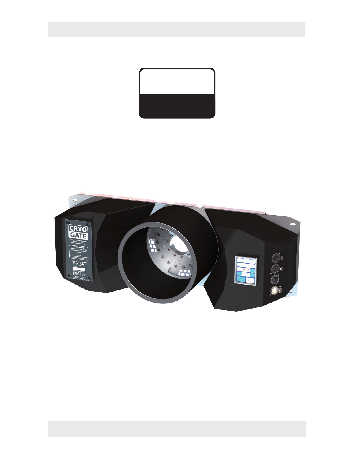
1. Introduction
The Cryo-Gate is a compact device that mates up to any professional fogger. It enab-
les the user to temporarily transform their existing fogger into a low fog generator.
The Cryo-Gate sits in front of the fogger‘s nozzle. A high-pressure dip-tube siphon
CO
2
tank connects to the unit and allows the user to add a variable amount of CO2 and
air to the fog‘s output. The result is a cold fog that stays low.
The connector to connect the delivered safety tube to the bottle has to be a
W 21.8 x 1 1/4“ right male (CGA 320 connector). If a tank with this connector cannot
be found, you have to use an adaptor.
A tube (Ø 200 mm) can be connected to the front of the Cryo-Gate to guide the fog
into the requested direction.
The tube can be around ten meters long, allowing to place the machine away from
the stage to avoid disturbing noise.
Holes at the Cryo-Gate ease mounting it to a rack or building it into a flightcase.
Please note: Only use quick disappearing fog fluid to avoid the chance that the fog
will get warm and rises.
Also cooled down fog will rise after some time!
Please read the manual carefully before starting the device to ensure a correct
operation!

5
2. Safety Instructions
A fog machine is not a toy!
• Make sure, that all persons who work with the bottle and the gas are professionals.
Incorrect use can cause the risk of suffocation!
• Carbon dioxide is not toxic but may cause asphyxiation in high concentrations.
• Carbon dioxide is heavier then air. The highest concentration is therefore at floor
level. The maximum allowed concentration is 0.5 Vol% (MAK: 5.000 ppm).
• Ensure adequate ventilation.
• Ensure all national/local regulations for handling and storage of liquid carbon dioxide
(CO
2
) are observed.
• Avoid dust or dirt particles inside the CO
2
-hose. Always ensure complete purity of all
CO
2
-connectors and fittings
• Extreme temperatures at the nozzle (hot/cold)! Danger of burning/frostbite.
• Occasionally very hot droplets of fluid may escape when in operation. Never aim at
persons directly and keep a minimum distance of 3 m from the nozzle.
• Never touch the nozzle when in operation. Danger of getting burnt.
• The location of the machine must be non-flammable, non-combustible and not
sensitive to heat. It must be twice as big as the machine.
• Keep a minimum distance of 60 cm to all flammable, combustible objects and objects
sensitive to heat.
• Glycol is alcohol and burns with a slightly bluish, almost invisible flame. Never point
the fog at strong sources of ignition like fire or pyrotechnic effects.
• Never open the machine and leave the machine unattended when connected to a
power supply.
• The visibility must be more than 2 m in rooms where people walk around.
• Do not swallow the fog liquid. Keep it away from children. In case of eye contact,
rinse with a lot of water. Consult a doctor should you accidentally swallow some
fluid.
6
2. Safety Instructions
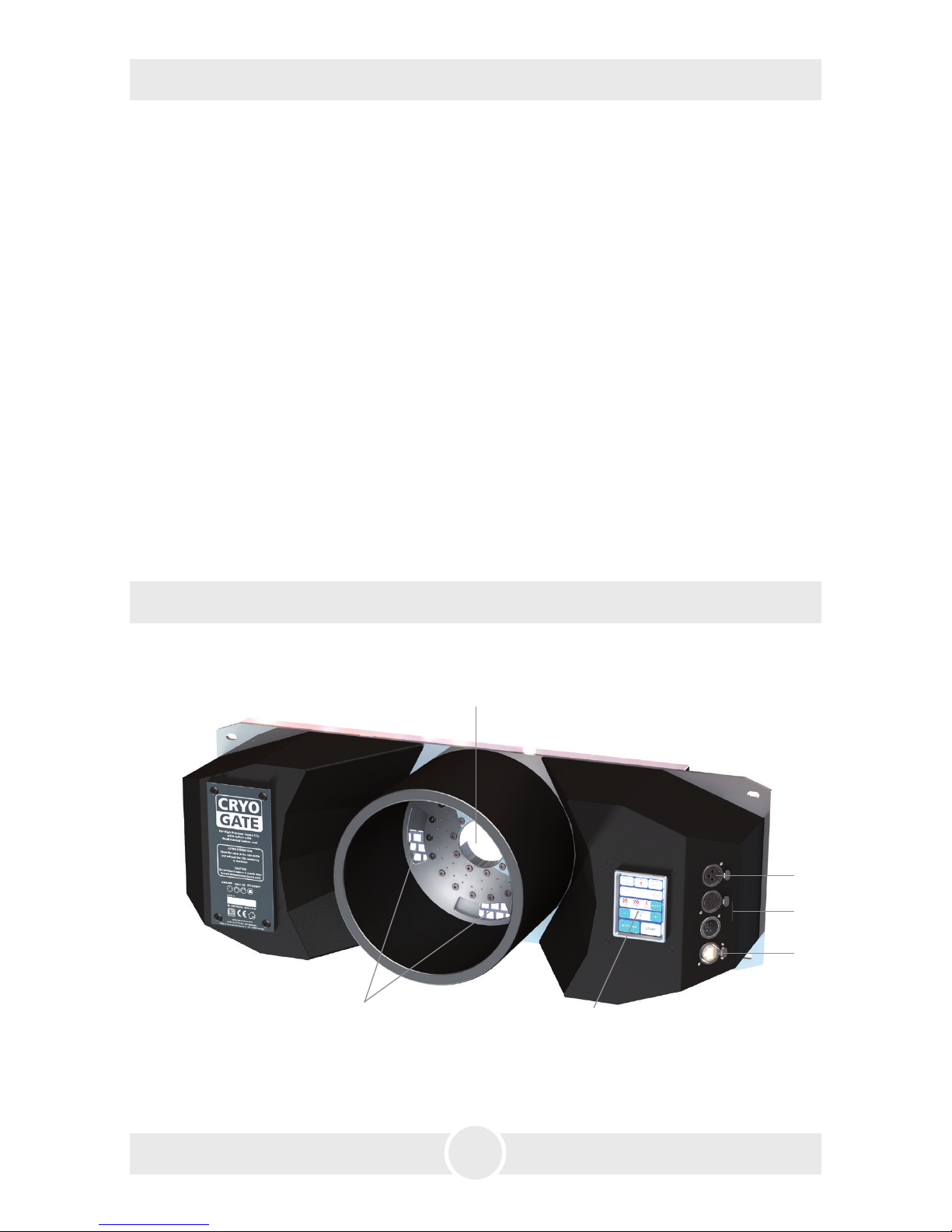
Front view
1: · Fog nozzle
2: · Air vents
3: · Touchscreen
4: · Analogue in 3pin-XLR
5: · DMX512 in/out 5pin-XLR
6: · Ethernet-Connector RJ45/Ethercon
2
3
4
5
6
1
3. Description of the parts
• Spilled liquid or splashed liquid droplets can cause slip hazard. Mop up the fluid and
dispose of it according to regulations.
• Fog may activate smoke detectors.
Artificially-made fog can be produced in many different ways. The method used here
to produce fog, with a device which works according to the vaporizer principle, is the
most harmless one.
No case has so far been reported in which a healthy human being has been harmed
because of using our device to produce artificial fog. However, this can only be guaranteed if the professional fog generators are used appropiately, i.e. at the correct
vaporization temperatures as well as with the correctly mixed fog fluid.
We, however, recommend: People with health problems or problems of the respiratory
tract or with an inclination for allergies should avoid any contact with artificially-made
fog.

7
Rear view
3. Description of the parts
7: · Power in/out for Powercon
8: · Analogue out 3pin-XLR
9: · DMX out 5pin-XLR
10: · Connector for liquid-CO
2
-tube
7
8
9
10
Connection to the high pressure CO2-tank with siphon tube
11
– Avoid dust or dirt particles inside the CO
2
-hose!
– Always ensure complete purity of all CO
2
-connectors and fittings!
11: · CO
2
-hose
12: · Inline-Filter
13: · CO
2
-connector Europe
14: · T-connector to connect several
CO
2
-tanks
15: · Valve
11
121213
13
14
15
15

8
4. Operating the Cryo-Gate
4.1 Putting into operation
1. Place a fog generator behind the Cryo-Gate.
The fog nozzle of the fog generator should be placed centric and approx. 1 to 2 cm
behind the nozzle of the Cryo-Gate.
If your fog machine is equipped with a PowerCon-plug (up to max. 3 kW/1.8 kW for
USA), connect it to the Power out plug [7] at the Cryo-Gate.
If your fog machine is not equipped with a PowerCon-plug, plug the mains cable of
your machine to a normal socket.
2. Also connect the fog generator with a 5 pin-XLR-cable via DMX [5] or with a 3 pin-
XLR-cable via analogue out [4] to the Cryo-Gate/analogue in at the fog generator.
If the fog generator is connected via DMX to the Cryo-Gate, make sure the adjusted
DMX start address at the fog generator is “001“.
3. Connect the CO
2
-tank to the Cryo-Gate [10], using the supplied safety hose (see page
7).
Always ensure complete purity of all CO
2
-connectors and fittings. If you should
notice dirt particles, connect the tube to the tank, tighten the connection to make
sure that no gas can come out, and open the valve at the bottle for a few moments.
CO
2
comes out at the end of the hose that has not been connected yet. Close the
valve properly and connect the other end of the tube to the Cryo-Gate [10].
Tighten both connections properly to make sure that no gas can come out. Open
the valve at the tank completely [15].
4. Connect the supplied PowerCon mains cable to the jack [7] at the Cryo-Gate. Turn
the plug until it is locked. Plug the power plug to a socket.
To use your fog generator in the right way, read the operating manual of the fog
machine.
After the fog generator has heated up completely, you can start the Cryo-Gate.
A ducting hose of 20 cm Ø can be connected to the front of the Cryo-Gate.
 Loading...