

Page 1

U9507E User Manual
Page 2

Contents
1.Introduction....................................................................................................................................................................3
1.1 Overview
1.2 Application scenario
.........................................................................................................................................................................
........................................................................................................................................................
2. U9507E interfaces......................................................................................................................................................... 4
2.1 U9507E interface summary
............................................................................................................................................
2.1.1 Test points..................................................................................................................................................................5
2.1.2 Mini PCIe Interface...................................................................................................................................................6
2.1.3 RF interface...............................................................................................................................................................9
2.2 U9507E interface application
........................................................................................................................................
10
2.2.1 RF antenna interface............................................................................................................................................. 10
2.2.2 Power supply and earth.........................................................................................................................................10
2.2.3 USB interface.......................................................................................................................................................... 11
2.2.4 USIM interface........................................................................................................................................................ 13
2.2.5 Audio interface*.......................................................................................................................................................14
2.2.6 PCM interface*........................................................................................................................................................16
2.2.7 UART interface*......................................................................................................................................................17
2.2.8 LED control..............................................................................................................................................................18
2.2.9 Others*..................................................................................................................................................................... 19
3. U9507E key features...................................................................................................................................................20
3.1 Internet access
3.2 SMS
3.3 GPS
...............................................................................................................................................................................
................................................................................................................................................................................
3.4 Phonebook
...............................................................................................................................................................
.....................................................................................................................................................................
20
20
21
21
4. Application Illustration..................................................................................................................................................21
4.1 Dial-up procedure
4.2 SMS
...............................................................................................................................................................................
..........................................................................................................................................................
21
22
4.2.1 Message Format.....................................................................................................................................................22
4.2.2 Set Message Storage Location............................................................................................................................22
4.2.3 PDU Format.............................................................................................................................................................23
4.2.4 TEXT Format...........................................................................................................................................................25
4.2.5 SMS Service Center Address Setting.................................................................................................................26
4.3 PHONE BOOK
...........................................................................................................................................................
27
4.3.1 Set Phone Book Storage Location......................................................................................................................27
4.3.2 Read Phonebook entries.......................................................................................................................................27
4.3.3 Write phonebook entry.......................................................................................................................................... 27
4.3.4 Find phonebook entries.........................................................................................................................................28
4.4 AUDIO
..........................................................................................................................................................................
28
4.4.1 Originate Call...........................................................................................................................................................28
4.4.2 Answer a incoming call..........................................................................................................................................28
4.4.3 Disconnect call........................................................................................................................................................28
5. Safety information........................................................................................................................................................ 28
6.Declaration of Conformity......................................................................................................................................... 29
7.Address of Manufacturer...........................................................................................................................................29
Appendix:Mechanical dimensions of U9507E
..........................................................................................................
29
3
3
4
Page 2 of 32
Page 3

1.Introduction
U9507E
LTE-TDD
38/40
LTE-FDD
1/3/5/7/8/20/28
UMTS
1/5/8
GSM
3/8
1.1 Overview
The LONGSUNG U9507E LTE wireless module, powered by Qualcomm MDM9207 chipset, can be integrated into
any devices for 4G mobile applications. It provides phone book, SMS、audio and GPS, as well as high speed internet
access to LTE,HSUPA,HSDPA, UMTS and GSM networks worldwide.
The U9507E module complies with the technical standard listed below:
·LTE
FDD: 150Mbps(DL), 50Mbps(UL)
TDD: 150Mbps(DL), 50Mbps(UL).
Support Release 10 category 4
·HSPA+
HSPA+: 42.2Mbps(DL), 5.76Mbps(UL)
·EDGE
3GPP R4, Class 12, up to 236.8 Kbps DL and 118.4Kbps UL
Mobile station class B
·GPRS
Up to 85.6 Kbps DL and 42.8 Kbps UL
The frequency bands supported:
It working at environment temperature: -40℃~+85℃。
1.2 Application scenario
The LTE U9507E wireless module support phone book, SMS, audio, GPS and Internet access functions. The
application of U9507E is as follows:
Page 3 of 32
Page 4
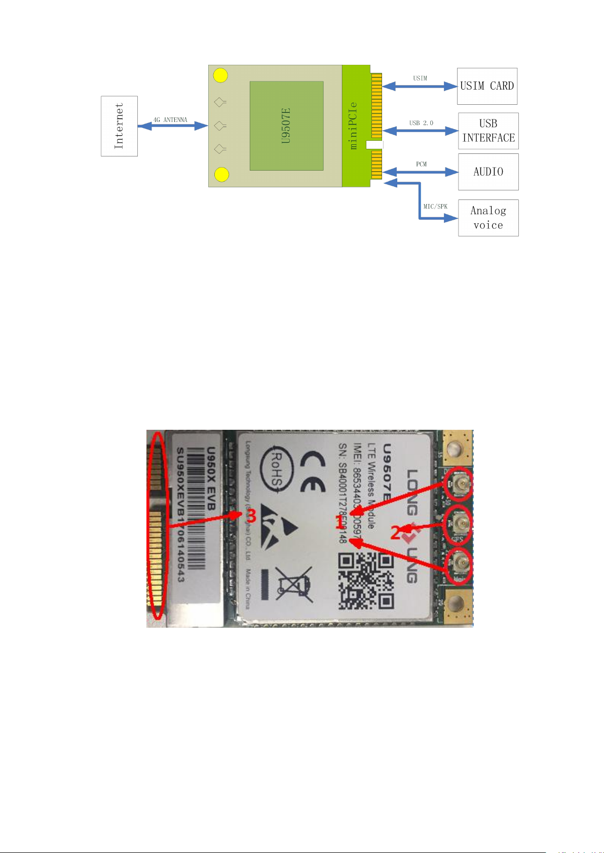
Figure1-1 U9507E application scenario
2. U9507E interfaces
2.1 U9507E interface summary
The LTE wireless module U9507E supports for multimode operation: LTE,HSUPA,HSDPA, UMTS and GSM. The
size of U9507E is 50.85×29.9×4.6mm. And the appearance is shown in Figure 2-1 and Figure 2-2.
Figure 2-1 The front view of U9507E
Page 4 of 32
Page 5
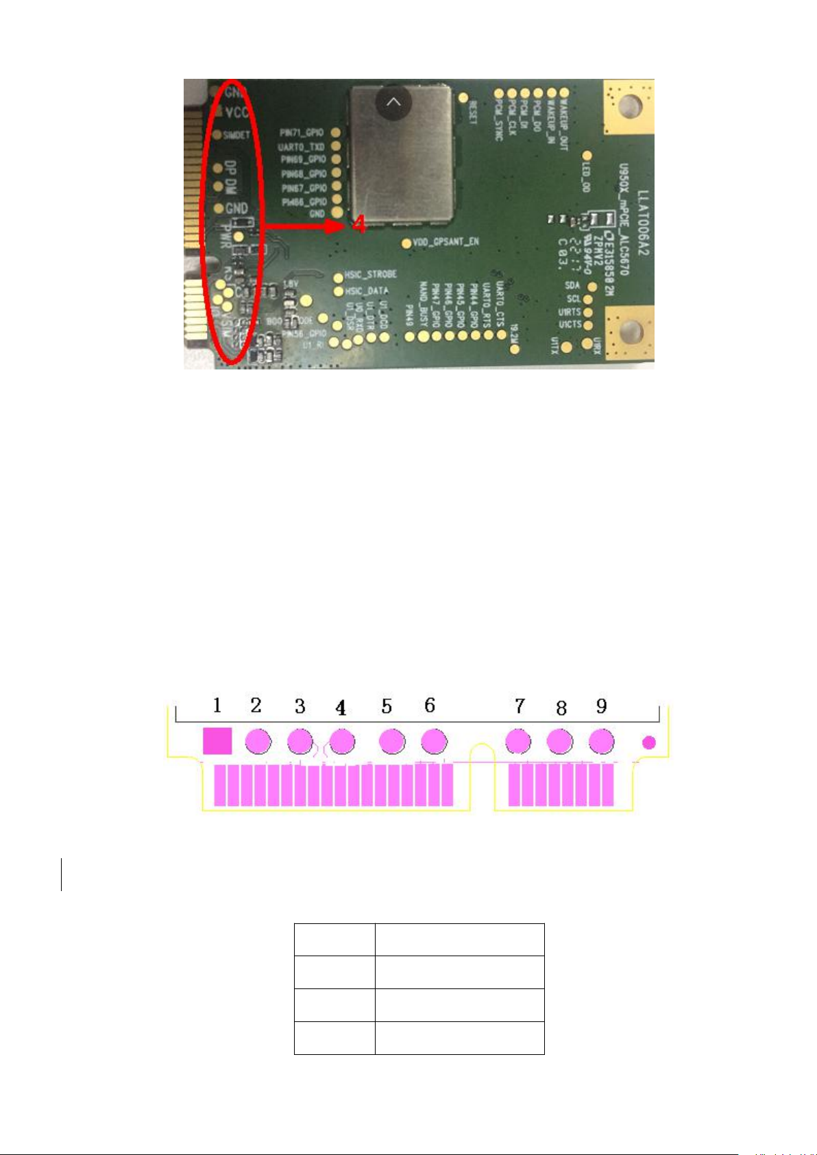
Figure 2-2 The rear view of U9507E
SN
Definition
1
U9507E Power Input
2
GND
3
USB DATA+
The antenna pads are show as part 1in the Figure 2-1, the below one is for the main antenna, and the upper one is
for the diversity antenna; The antenna pad which is shown as part 2 in Figure 2-1 is for GPS application; A miniPCIe
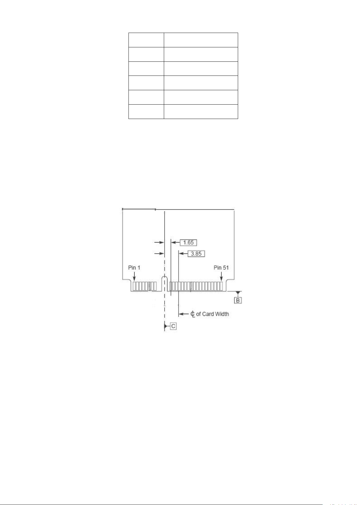
interface is shown as part 3 in Figure 2-1; U9507E module also offers some test points, they are shown as part 4 in
Figure 2-2
2.1.1 Test points
The test points of U9507E are displayed in figure 2-3, and the definition of each point is listed in table 2.1.
Figure 2-3 Test points of U9507E
Table 2.1 The definition of U9507E test points
Page 5 of 32
Page 6
4
USB DATA-
5
GND
6
USIM Card Reset
7
USIM Card Clock
8
USIM Card Data
9
USIM Card Power
2.1.2 Mini PCIe Interface
A Mini PCIe Interface is used, two primary data interfaces are defined for PCI Express Mini Card: PCI Express and
USB. For more information, please refer to the PCI Express®Mini Card Electromechanical Specification Revision 1.1
Figure 2-4 show the Mini PCIe Interface.
For protecting the connector from electro-static, it is better to use the ESD element. And the ESD element should be as
close as possible to connector. The definition of the PINs in Mini PCIe Interface is listed in table 2.2 below.
Figure 2-4 The Mini PCIe Interface
Page 6 of 32
Page 7
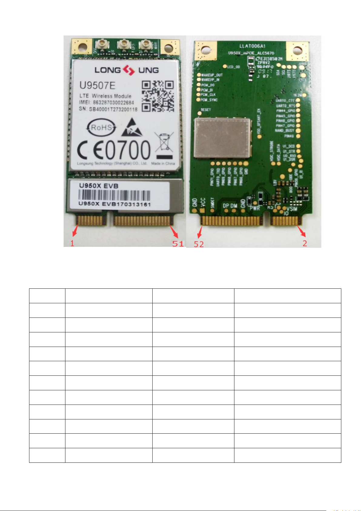
Figure 2-5 The Mini PCIe Interface pin sequence of U9507E
SN
Definition
Description
Remark
1
MIC_P*
MIC Data+
Audio Interface
3
MIC_N*
MIC Data+-
Audio Interface
5
LINEOUT_P*
Speaker Out+
Audio Interface
7
LINEOUT_N*
Speaker Out-
Audio Interface
9
GND
Ground
11
VOUT*
Power Output
1.8V
13
NC
NC
NC
15
GND
Ground
17
NC
NC
NC
19
WAKEUP_IN*
Wakeup The Module
Active low
21
GND
Ground
Table 2.2 The definition of Mini PCIe Interface
Page 7 of 32
Page 8

23
UART_RXD*
Rx of UART
UART Interface
25
NC*
NC RTS of UART -
27
GND
Ground
29
GND
Ground
31
UART_TXD*
Tx of UART
UART Interface
33
RESET*
External Reset to U9507E
35
GND
Ground
37
GND
Ground
39
VBAT
Power Supply
41
VBAT
Power Supply
43
GND
Ground
45
PCM_CLK*
PCM CLK
PCM Interface
47
PCM_DIN*
PCM Data Input
PCM Interface
49
PCM_DOUT*
PCM Data Output
PCM Interface
51
PCM_SYNC*
PCM Synchronization
PCM Interface
2
VBAT
Power Supply
4
GND
Ground
6
NC
NC
NC
8
USIM_VCC
UIM Power
UIM Interface
10
UIM_DATA
UIM Data
UIM Interface
12
UIM_CLK
UIM CLK
UIM Interface
14
UIM_RESET
UIM Reset
UIM Interface
16
NC
NC
NC
18
GND
Ground
20
W_DISABLE
External Disable signal
Active low signal. This signal is used by the
system to disable radio operation on add-in
cards that implement radio frequency
applications
22
RESET*
External Reset to U9507E
24
VBAT
Power Supply
26
GND
Ground
Page 8 of 32
Page 9
28
NC
NC
NC
30
NC
NC
NC
32
WAKEUP_OUT*
Wakeup The AP/MCU
34
GND
Ground
36
USB_DM
USB Data-
USB Interface
38
USB_DP
USB Data+
USB Interface
40
GND
Ground
42
PWM_OUT
Led control Signal
44
NC
NC
NC
46
NC
NC
NC
48
NC
NC
NC
50
GND
Ground
52
VBAT
Power Supply
2.1.3 RF interface
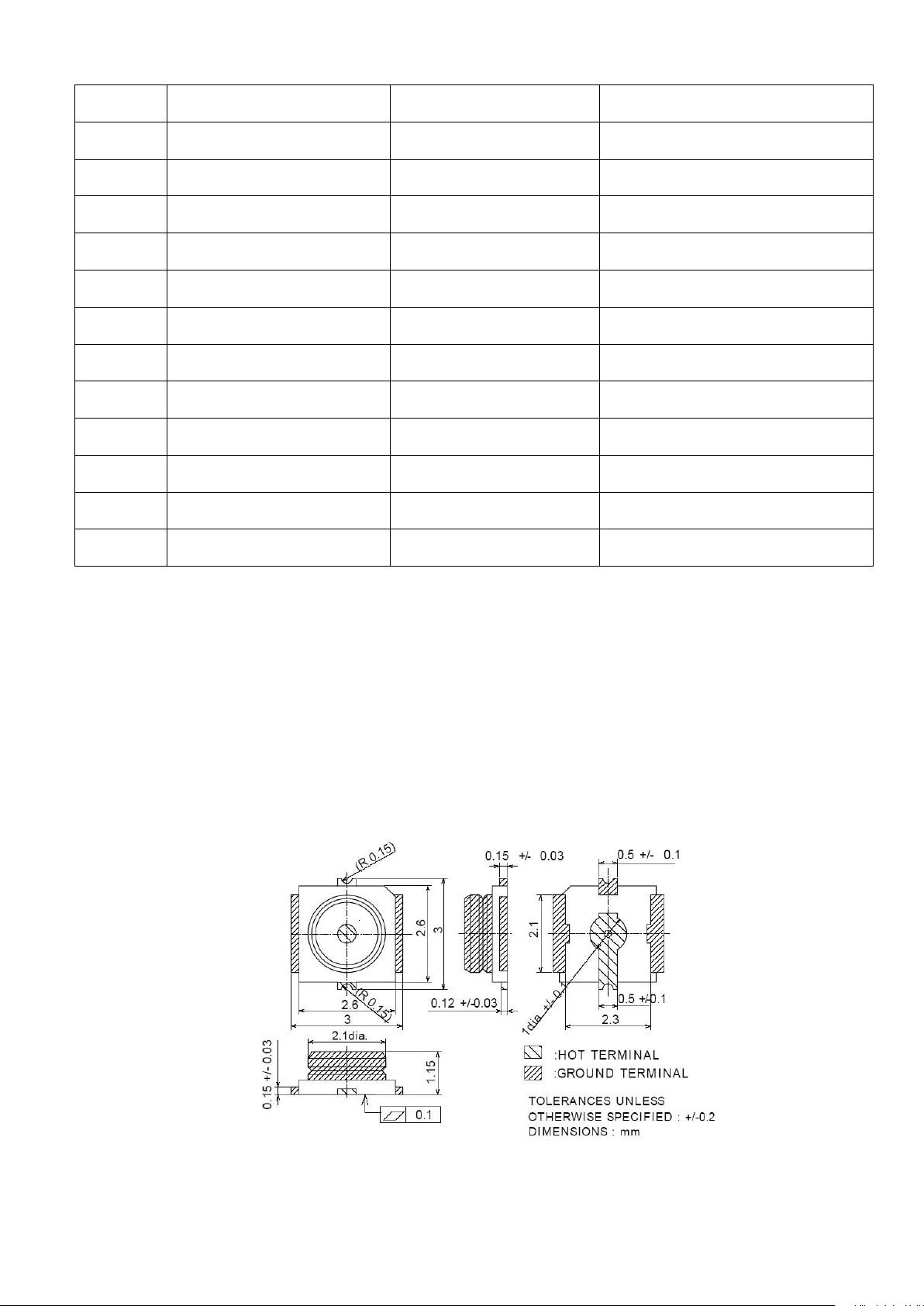
U9507E uses HRS’s U.FL-R-SMT-1(10) RF connector on the module side. There are three RF connector on
U9507E,from right to left: main antenna / GPS antenna* / diversity antenna.
The RF connector is showed in figure 2-6.
Figure 2-6 The sketch map of RF connector
Page 9 of 32
Page 10

2.2 U9507E interface application
Item
Parameter
Plus(dBi)
GSM
DCS
UMTS
0.511
Type
Omni directional antenna
U9507E supplies multifold functional interface by a Mini PCIe Interface, such as , USIM card interface, USB interface,
audio interface*, UART interface*, PCM(Pulse Code Modulation) interface*and power supply interface and so on.
The detail information will be given in the follow sections.
2.2.1 RF antenna interface
The impedance of RF antenna is 50Ω.
The three connector is on the top of U9507E;
For minimizing the wasting of RF cable, user should pay more attention to make choice. We suggest choosing the cable
that satisfies:
• GSM900/LTE BAND5/LTE Band8/LTE BAND 20/LTE BAND28/WCDMA
BAND5/WCDMA BAND8<1dB
• DCS1800/LTE Band1/LTE Band3/WCDMA BAND1 <1.5dB
• LTE Band7/Band38/Band40<2dB
And the antenna should satisfy the table below:
2.2.2 Power supply and earth
The power supply needed by U9507E, is listed as follow:
1. Voltage range DC:3.3V~4.2V , the power for U9507E working;
2. The earth point: GND;
The description of U9507E Power and GND pins is shown in the table 2.3 below.
Table 2.3 The description of U9507E Power and GND pins
Page 10 of 32
Page 11

Power input
SN. of the Mini PCIe
Interface
VBAT
2, 24, 39, 41,52
GND
4, 9, 15, 18,21, 26, 27, 29, 34,
35, 37, 40, 43, 50
2.2.3 USB interface
Signals offered
by
USB interface
The name of the correlative
pins in
Mini PCIe Interface
SN. of the Mini
PCIe Interface
Description
USB_VBUS
VBAT
2, 24, 39, 41,52
USB power
DM
USB_DM
36
USB Data-
DP
USB_DP
38
USB Data+
GND
GND
4, 9, 15, 18,21, 26, 27,
29, 34, 35, 37, 40, 43,
50
GND
2.2.3.1 Description
U9507E offers a high-speed USB interface by Mini PCIe Interface, which submits to USB 2.0 protocol. The detail
information is given in table 2.4 below.
Table 2.4 U9507E USB interface description
2.2.3.2 Reference circuit
The reference circuit of USB interface is shown in figure 2-7.
1)For getting the steady-going USB power supply, it is recommended that a 10uF(C406)filter capacitor and a 22pF
(C407)filter capacitor should be used.
2) For reducing the BER of USB transmission, it is recommended to add a resistor with values below 10 Ω to the
DM and DP in USB interface. Just like the resistors R408 and R409 in figure 2-7.
Page 11 of 32
Page 12
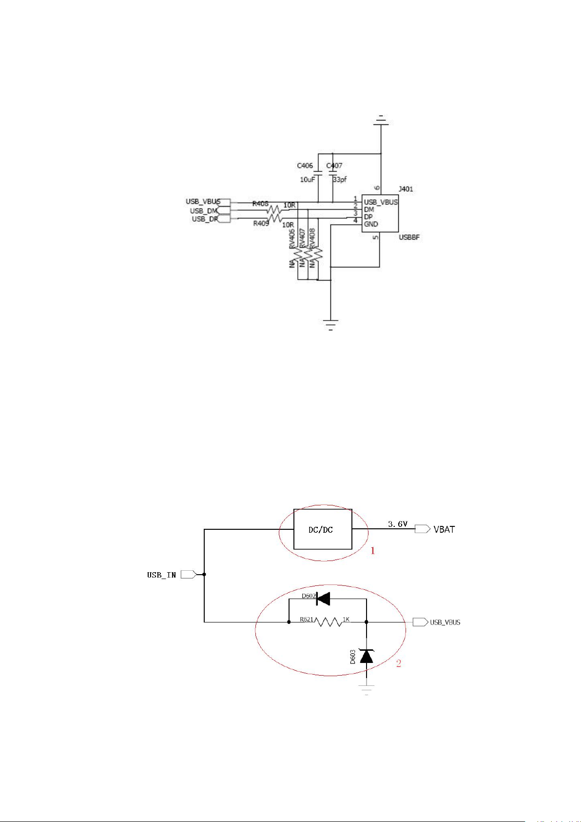
3)For avoiding the electro-static in USB interface, it is recommended to use the ESD element. Just like the voltage
dependent resistors RV406, RV407 and RV408 with the static capacitance values below 3pF.
Figure 2-7 The reference circuit of USB interface
4)The USB interface input the voltage from USB_IN .For keeping the USB in U9507E module working unfailingly,
a voltage protection circuit should be added by user between the USB_IN of USB interface and the USB_VBUS PIN of
U9507E. It is shown in figure 2-8 with the red circle 2. In the voltage protection circuit, D603 is a Zener diode with a
breakdown voltage value of 5.1v which could keep the voltage on the USB_VBUS PIN of U9507E not more than
5.1v. D602 is a Schottky Diode, and R621 is a resistor with the value 1KΩ. On the other hand the voltage coming
from the USB_IN also could be converted by using a DC/DC converter to 3.6v and then be sent to VBAT PIN of
U9507E. It is shown in figure 2-8 with the red circle 1.
Figure2-8 The reference of voltage protection circuit
Page 12 of 32
Page 13

2.2.4 USIM interface
Signals offered
by
USIM interface
The name of the correlative
pins in
Mini PCIe Interface
SN. of the Mini PCIe
Interface
Description
DATA
UIM_DATA
10
UIM card data
CLK
UIM_CLK
12
UIM card CLK
RST
UIM_RESET
14
Reset signal
VCC
USIM_VCC
8
UIM card power
GND
GND
4, 9, 15, 18,21, 26, 27, 29,
34, 35, 37, 40, 43, 50
GND
U9507E supports LTE, UMTS and GSM operation mode.USIM card as well as SIM card can be used.
2.2.4.1 Description
U9507E offers USIM card interface by Mini PCIe Interface. And it can be used in LTE,UMTS and GSM/GPRS/EDGE
networks. The table 2.5 gives the more detail information.
Table 2.5 U9507E USIM card interface description
2.2.4.2 Reference circuit
The reference circuit of USIM interface is shown in figure 2-9.
1)The DATA line of USIM is connected to SIM power by a pull-up resistor, and the reference value is 15KΩ.
2)For avoiding the instantaneous voltage overflowing, the resistor with the reference value 22Ω can be used for the
DALA, CLK and RST. Just like the resistors R307, R308 and R309 in figure 2-8.
3)For avoiding the electro-static in USIM socket, it is recommended to use the ESD element to the DATA,CLK and
VCC. Just like the voltage dependent resistors RV301, RV302, RV303 and RV304 in figure 2-8. And the ESD
element should close to the USIM socket as close as possible.
4)For getting the more smooth USIM power supply, it is recommended to use the filter capacitors. Just like C311 and
Page 13 of 32
Page 14
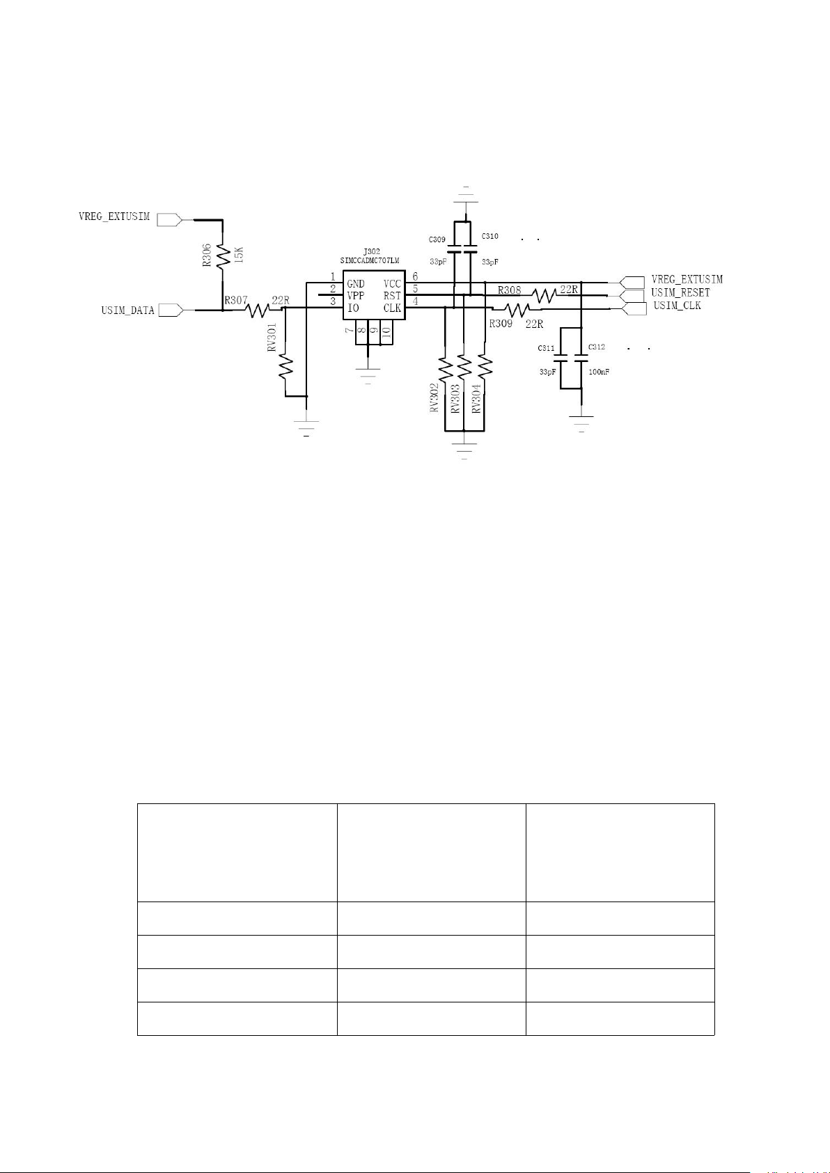
C312 in figure 2-8, and their reference values are 33pF and 100nF.
The name of the correlative
pins in
Mini PCIe Interface
SN. of the Mini PCIe
Interface
Description
LINEOUT_P
5
Audio output data+
LINEOUT_N
7
Audio output data-
MIC_P
1
Audio input data+
MIC_N
3
Audio input data-
5)In order to remove the unwanted peak signal and the elimination high frequency interference which produces on RST
and CLK, the filter capacities (C310, C309) can be placed in RST and the CLK end, the reference value is 33pF.
Figure 2-9 The reference circuit of USIM interface
2.2.5 Audio interface*
The audio signals here include a pair of input difference signals ( MIC1_P, MIC1_N)and a pair of output difference
signals (EAR1OP,EAR1OR). And the Audio interface here includes the earphone jack and the test points.
2.2.5.1 Description
The audio signals offered by U9507E are described in the table 2.7 below.
Table 2.7 U9507E audio signal description
Page 14 of 32
Page 15
2.2.5.2 The connection between audio I/O and earphone
The PIN name of
earphone jack
he name of the correlative pins in
Mini PCIe Interface
SN. of the Mini PCIe
Interface
Description
Left Speaker
LINEOUT_P
5
The left output of stereo
Right Speaker
LINEOUT_N
7
The right output of stereo
MIC
MIC_P
1
The microphone input
PGND
GND50Analog ground signal
Signals
offered by
phone handle
The name of the correlative
pins in
Mini PCIe Interface
SN. of the Mini PCIe Interface
Description
EAR_P
LINEOUT_P
5
Audio output data+
EAR_N
LINEOUT_N
7
Audio output data-
MIC_P
MIC_P
1
Audio input data+
MIC_N
MIC_N
3
Audio input data-
The audio I/O signals offered by U9507E can be connected to a stereo earphone jack. The more detail information
about connection between earphone jack and the Mini PCIe Interface is shown in table 2.8 below. And the information
about test points is shown in table 2.1 above.
Table 2.8 The connection between earphone jack and the Mini PCIe Interface
2.2.5.3 The connection between audio I/O and phone handle
The audio I/O signals offered by U9507E can be connected to a phone handle. The more detail information about
connection between phone handle and the Mini PCIe Interface is shown in table 2.9 below.
Table 2.9 The connection between phone handle and the Mini PCIe Interface
2.2.5.4 Reference circuit
The reference circuit of audio interface is shown in figure 2-11.
Page 15 of 32
Page 16
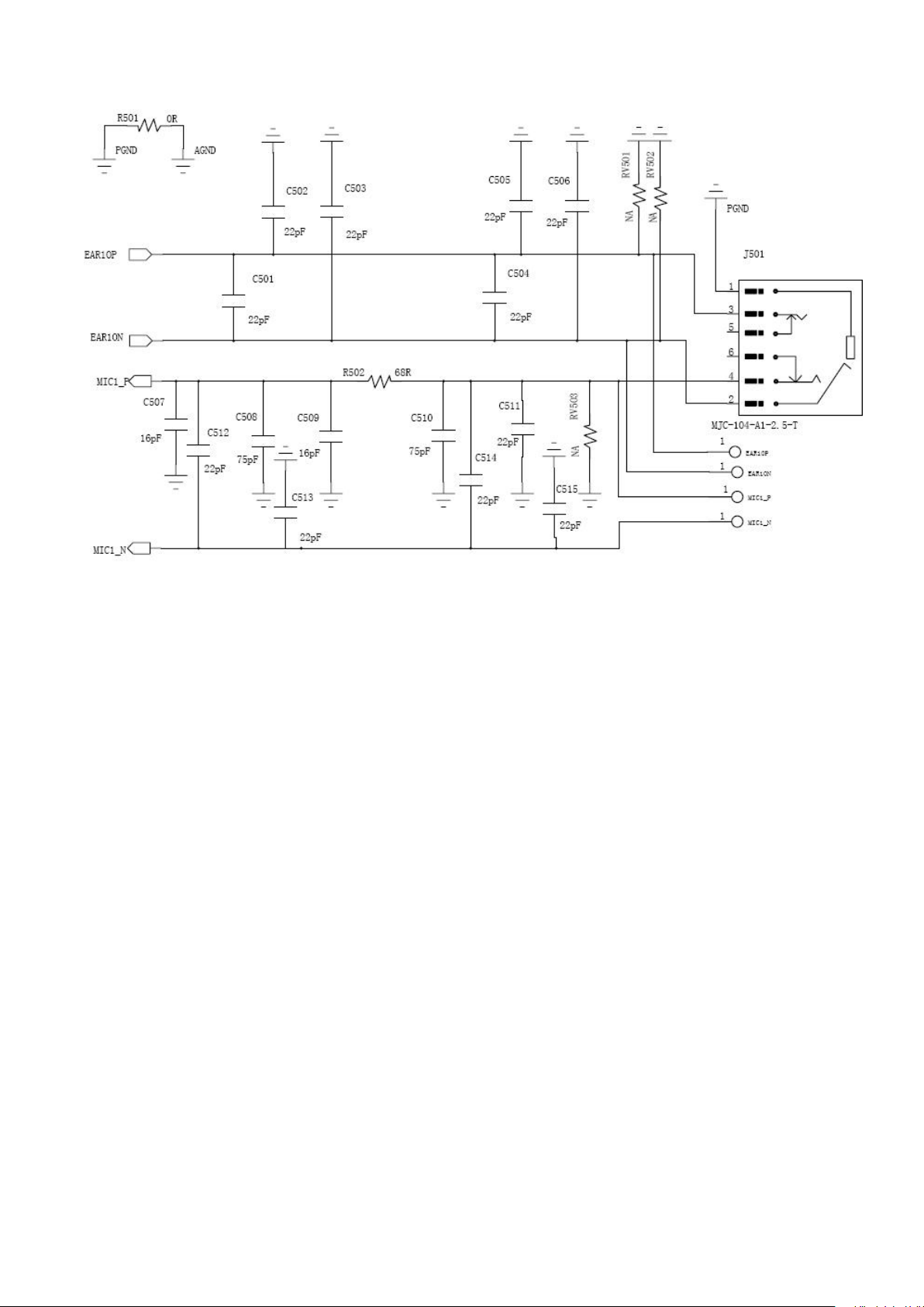
Figure 2-11 The reference circuit of audio interface
1)The audio output signals, a pair of difference signal, export to two receivers. And they are not the real traditional
dimensional sound.
2)It is recommended to use the smoothing capacitor or smoothing circuit for reducing the undesired signal between
different frequency bands. Just like what is shown in figure 2-9.
3)For avoiding the electro-static, it is recommended to use the ESD element. Just like the voltage dependent resistors
RV501, RV502 and RV503 in figure 2-10.
4)Designers needs gets up the acoustic train signaling analogous circuit ground terminal and the entire digital circuit
earth end connection, bead or 0 ohm resistance can be used.
5) In the chart J501 is a four section of earphone jack schematic diagram electric circuit, you can see audio output
signal connecting difference signal while audio input signal connecting one negative signal.
2.2.6 PCM interface*
U9507E offers Micro the PCM interface and the SPI interface by Mini PCIe Interface. And the SPI interface is
simulated by GPIO PIN.
Page 16 of 32
Page 17

2.2.6.1 PCM interface description
Signals offered
by PCM
The name of the correlative pins in
Mini PCIe Interface
SN. of the Mini
PCIe Interface
Description
SYNC
PCM_SYNC
51
PCM Synchronous Signal
CLK
PCM_CLK
45
PCM CLK
D ATA_IN
PCM_DIN
47
PCM Input
D ATA_OUT
PCM_DOUT
49
PCM Output
Signals offered
by UART
The name of the correlative
pins in
Mini PCIe Interface
SN. of the Mini PCIe
Interface
Description
RX
UART_RXD
23
TX
UART_TXD
31
GND
GND
4, 9, 15, 18,21, 26, 27, 29,
34, 35, 37, 40, 43, 50
The information about PCM interface offered by U9507E is described in table 2.10 below.
Table 2.10 U9507E PCM interface description
2.2.7 UART interface*
U9507E offers a UART interface (RS232) by Mini PCIe Interface for debugging.
2.2.7.1 Description
The information about UART interface offered by U9507E is described in table 2.12 below.
Table 2.12 U9507E UART interface description
2.2.7.2 Reference circuit
The reference circuit of UART interface is shown in figure 2-12.
1)As the UART of U9507E can only supply TTL level while the PC serial port level is the RS232 level, the signal level
between them must use level transformation chip. The reference IC is SP3238EEA which produces by SIPEX, as
Page 17 of 32
Page 18
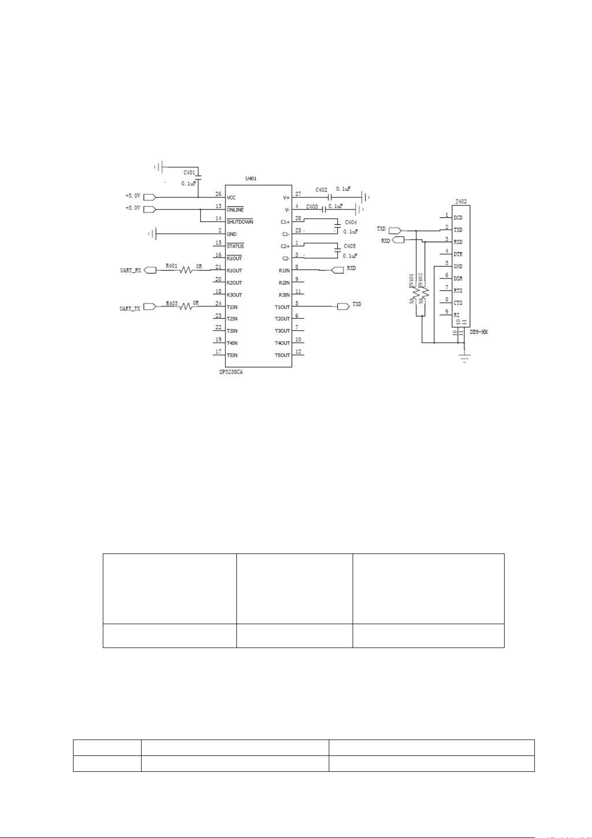
shown in Figure 2-11. J401 is a 9 needle serial port plugs,we can use it to connect U9507E and PC.
LED
Status
Description
Green
Flicker quickly (100ms On/800ms Off)
Networks searching
The name of the
correlative pins in
Mini PCIe Interface
SN. of the Mini PCIe
Interface
Description
PWM_OUT
42
Led control Signal
2)For avoiding the electro-static, it is recommended to use the ESD element to the signal line of the UART socket. Just
like the voltage dependent resistors RV401, RV402, RV403, RV404 and RV405 in figure 2-11.And the ESD
element should close to the socket as close as possible.
Figure 2-12 The reference circuit of UART interface
2.2.8 LED control
2.2.8.1 Description
There is a pins for LED control in the Mini PCIe Interface. And the detail information is given in table 2.13 below.
Table 2.13 U9507E LED control description
And the U9507E status displayed by LEDs is listed in table 2.14 below.
Table 2.14 LED display description
Page 18 of 32
Page 19
Flicker slowly(100ms On/3000ms Off)
Registered in 3G networks
Always On
Connected to 3G networks, but no data transmitting
Off
Closed or error(No SIM card or failed in registering
networks )
2.2.8.2 Reference circuit
The name of the correlative pins in
Mini PCIe Interface
SN. of the Mini PCIe
Interface
Description
RESET
33, 22
Reset signal for U9507E
VOUT
11
VREG_MSMP Output,1.8V
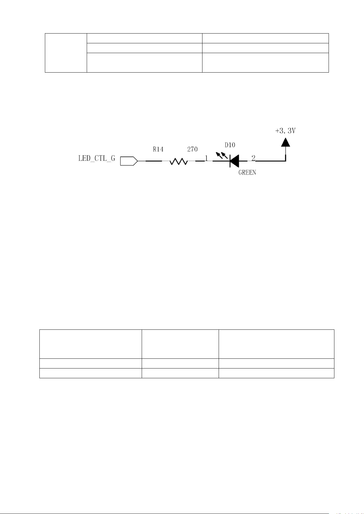
The reference circuit for LED is shown in figure 2-13.
Figure 2-13 The reference circuit of LED control
1) The LED control pin connects to the cathode of LED. And the anode of LED connects to the +3.3v power in figure
2-12.
2)The value of electrical current must be below than 10mA. And the reference value is 5mA. So the current-limiting
resistor may be used. Just like the resistor R14 in figure 2-12
3)The reference circuit given is for the Green LED, and it is the same for the Red one.
2.2.9 Others*
U9507E also offers some other functional interfaces besides those which have been described above.
These signals are listed in table 2.15 below.
Table 2.15 The other signals offered by U9507E
1) U9507E offers a power supply named VREG_MSMP, its value is +1.8V and the Max. value of electric current is
100mA.
2) EXT_RST_N is used for reset the U9507E module. And U9507E will be reseted just by putting the EXT_RST_N
to GND;
For only keeping the SMPL (Sudden momentary power losing) timer while Sudden momentary power losing, a
capacitor can be used inside of battery. And the correlativity between the capacitance and the holding time is listed in
Page 19 of 32
Page 20

table 2.16.
The capacitance
The Packaging (X5R)
The holding time
1.5uF
0805
0.5
3.3uF
0805
1.0
4.7uF
0805
1.5
6.8uF
1206
2.0
Table 2.16 the correlativity between the capacitance and the holding time
3. U9507E key features
The U9507E module has features such as internet access, SMS, GPS, phone book and audio. The features are described
in following sections. For detail information about AT commands, please make refers to the related documents.
3.1 Internet access
AT commands can be used for selecting network mode, setting the network search mode, setting register mode,
querying network signal strength, setting APN and so on. The related AT commands are listed as follows:
·Network Mode Set: AT+MODODREX=<mode >
·Network Mode Query: AT+MODODREX?
·Network Mode Service Query: AT+MODPRF?
·Network Query: AT+PSRAT
Querying network signal strength:AT+CSQ
·PIN and PUK Remain Times Query: AT+CPNNUM
·APN Set: AT+CGDCONT=1,"IP","CMNET"
·Dial up Access: ATDT*99***1#
·PS DATA CALL Disconnecting: ATH
3.2 SMS
The SMS feature is implemented by AT commands. You can set the service center address, switch message format,
enable/disable receiving message report, delete message, preview message, receive/send message and so on.
Page 20 of 32
Page 21

The related AT commands are listed as follow:
SN.
Type
AT Command/Respond
Explain
1SAT+CPIN?
SIM card querying
2RREADY
3SAT+CPNNUM
PIN And PUK querying
·New Message Indication: AT+CNMI
·Message Send: AT+CMGS
·Message Preview: AT+CMGPR
·Message Delete: AT+CMGD
·Message format Switch: AT+CMGF
·Service Center Address Set: AT+CSCA
·Receiving Message Report enable/disable: AT+CNMI=2,1,0,1,0
3.3 GPS
GPS functions are only available in the U9507E module. The related AT command as follow:
AT+GPSFIX originate GPS request
AT+GPSCFG configure GPS parameter
3.4 Phonebook
The Phonebook feature is implemented by AT commands. You can set the phonebook storage location, read phone
number, write phone number and delete phone number and so on.
The related AT commands are listed as follow:
AT+CPBS=<storage> set the storage location
AT+CPBR=<index> read phone number
AT+CPBW=[<index>][,<number>[,<type>[,<text>]]] write phone number on the phone.
AT+CPBW=[<index>] delete phone number.
AT+CPBF=<findtext> find the phone number according to the findtext.
4. Application Illustration
4.1 Dial-up procedure
The type “S” means the AT Command sent to U9507E, and the type “R” means Respond from U9507E.
Page 21 of 32
Page 22

4RPIN1=3; PUK1=10; PIN2=0; PUK2=8
5SATD10086;
Doing cs call
6RAT+CHUP
Hung up the cs call
7SAT+CIMI
Get IMSI
8R460020177608847
IMSI, by which APN is selected
9SAT+CGDCONT=1,"IP","CMNET"
Set APN
10ROK
11SATDT*99***1#
Dial-up
12SATH
Disconnect the PS call
4.2 SMS
4.2.1 Message Format
U9507E supports two kinds of message format, PDU and TEXT which can be set by AT command AT+CMGF,
AT+CMGF=0 means PDU format, and AT+CMGF=1 means TEXT format.
4.2.2 Set Message Storage Location
The command AT+CPMS=<mem1>,<mem2>,<mem3> is used to set message storage location.
<mem1>, <mem2>, <mem3> can be set as SM and ME, SM means SIM card,ME means the U9507E module.
<mem1>: The parameter set here means memory storage used as read and delete message function. It can be operated
by the followed AT commands: AT+CMGL, AT+CMGR and AT+CMGD;
<mem2>: The parameter set here means memory storage used as writing and send message function. It can be operated
by the followed AT commands: AT+CMSS and AT+CMGW;
<mem3>: Received messages will be storage in this memory if routing to PC is not set;
Response:
If no error:
+CPMS:<used1>,<total1>,<used2>,<total2>,<used3>,<total3>
OK
<used1, 2, 3> Number of messages currently storage in <mem1, 2, 3>
Page 22 of 32
Page 23

<total1, 2, 3> Number of message capacity of <mem1, 2, 3>
SN.
Type
AT Command/Respond
Explain
1SAT+CSCS=" UCS2"
Select TE character set
2ROK
3SAT+CMGF=0
Select message PDU format
4ROK
5SAT+CMGS=26
0011000D91683198916718F30000000CC8329BFD0
65DDF72363904
<ctrl-Z>
Send message
6R+CMGS: 2
OK
Send successfully
If error:
+CMS ERROR:<err>
The command AT+CPMS? is used to display the remained capacity of memory.
AT+CPMS?
Response:
If no error:
+CPMS:<mem1>,<used1>,<total1>,<mem2>,<used2>,<total2>,<mem3>,<used3>,<total3> OK
If error:
+CMS ERROR
4.2.3 PDU Format
Sending:
The type “S” means the AT Command sent to U9507E, and the type “R” means Respond from U9507E.
Writing message to memory:
The type “S” means the AT Command sent to U9507E, and the type “R” means Respond from U9507E.
Page 23 of 32
Page 24

SN.
Type
AT Command/Respond
Explain
1SAT+CMGW=26
0011000D91683198916718F30000000CC8329BFD0
65DDF72363904
<ctrl-Z>
Write a message
2R+CMGW: 6
OK
Memory location index 6 of the stored
message is returned.
Receiving message:
SN.
Type
AT Command/Respond
Explain
1SAT+CMGR=0
Read message has been received in the
memory location index 0
2R+CMGR: 0,,24
0891683108200905F0240D91683198916718F3000
880509111258023047A7A8C03
OK
Read successfully
SN.
Type
AT Command/Respond
Explain
1SAT+CMGD=0
Delete message from preferred memory
location index 0.
2ROK
Delete successfully
+CMTI: "SM",0
Means new received message in the memory located from index 0.
Reading message:
The type “S” means the AT Command sent to U9507E, and the type “R” means Respond from U9507E.
Deleting message:
The type “S” means the AT Command sent to U9507E, and the type “R” means Respond from U9507E.
Page 24 of 32
Page 25

4.2.4 TEXT Format
SN.
Type
AT Command/Respond
Explain
1SAT+CSCS=" GSM"
Select TE character set
2ROK
3SAT+CMGF=1
Select message TXT format
4ROK
5SAT+CMGS="13572034257"
> 1233455664788666555
<ctrl-Z>
Send message
6R+CMGS: 4
OK
Send successfully
SN.
Type
AT Command/Respond
Explain
1SAT+CMGW="13572034257"
> 11111114
<ctrl-Z>
Write a message
2R+CMGW: 8
OK
Memory location index 8 of the stored
message is returned.
Sending:
The type “S” means the AT Command sent to U9507E, and the type “R” means Respond from U9507E..
Writing message to memory:
The type “S” means the AT Command sent to U9507E, and the type “R” means Respond from U9507E..
Receiving message:
+CMTI: "SM",1
Means new received message in the SIM card located index is 1.
Reading message:
The type “S” means the AT Command sent to U9507E, and the type “R” means Respond from U9507E.
Page 25 of 32
Page 26

SN.
Type
AT Command/Respond
Explain
1SAT+CMGR=8
Read message has been received in the
memory location index 8
2R+CMGR: 0,,24
+CMGR: "STO UNSENT","13572034257",
11111114
OK
Read successfully
Deleting message:
SN.
Type
AT Command/Respond
Explain
1SAT+CMGD=8
Delete message from preferred memory
location index 8.
2ROK
Delete successfully
SN.
Type
AT Command/Respond
Explain
1SAT+CSCA=”+8613800201500”,145
Set the SMS service center address, and the
address will be kept in SIM card.
2ROK
3SAT+CSMP=17,167,0,8
Set the TP-Validity-Period as 167(24
hours) ,and the SMS Data Coding Mode as
UCS2
4ROK
The type “S” means the AT Command sent to U9507E, and the type “R” means Respond from U9507E. The type “S”
means the AT Command sent to U9507E, and the type “R” means Respond from U9507E.
4.2.5 SMS Service Center Address Setting
The user can set the SMS service center address, TP-Validity-Period and SMS Data Coding Mode.
Remark:
1) TP-MTI supports SMS-DELIVER, SMS-SUBMIT and SMS-STATUS-REPORT, while not support SMS-
DELIVER-REPORT, SMS-SUBMIT-REPORT and SMS-COMMAND.
2) TP-PID is 0 by default while TPDU is sending or saving.
3) The Min. length of <pdu> is 8 and the Max. length of <pdu> is 164 while TPDU is sending or saving,.
Page 26 of 32
Page 27

4) The parameter <stat> can only be 2 for the command AT+CMGW.
5) In TEXT Format, the parameter <fo> can be 17 and 49, the parameter <pid> can only be 0, the parameter
<dcs> can be 0~31 and the parameter <vp> can be 0~255 for AT+CSMP command
6) In TEXT Format, the parameter <stat> can only be ”STO UNSENT” for the command AT+CMGW
4.3 PHONE BOOK
4.3.1 Set Phone Book Storage Location
Phone book storage location can be set by AT command AT+CPBS. The AT command can be used in three ways.
Performing AT+CPBS? will return the current storage location of the phone book. Such as
+CPBS:<storage>[,<used>,<total>].The parameter <total> indicated how many phone numbers can be stored on the
phone. The parameter <used> indicates how many phone numbers have been stored.
Performing AT+CPBS=? will return all the storage type which the phone supports. Such as +CPBS:(list of supported
<storage>s).
We can use AT+CPBS=<storage> to set storage location. There are six types storage location. It’s follow as:
“LD” --store the recently call number which have dialed (SIM).
“MC” --store the recently call number which haven’t answered.
“RC” --store the recently call number which have been answered.
“ON” -- store the phone number of itself.
“ME” --NVRAM storage
“SM” --SIM storage
4.3.2 Read Phonebook entries
When you want to read phonebook entries, you can use AT command AT+CPBR.
Performing AT+CPBR=? will list of supported index, phone number length and text length.
Performing AT+CPBR=<index1>[,<index2>] will return the content of the phonebook entry of index1. If we use
index1 and index2 at the same time ,it will return all the entries between index1 and index2. Such as
[+CPBR:<index1>,<number>,<type><text>[[...]<CR><LF>+CPBR:<index2>,<number>,<type><text>]]
The parameter <type> include 129 and 145.145 indicate which is a international phone number. 129 indicate which is a
unknown type number.
The parameter <text> is the tag of the number.
4.3.3 Write phonebook entry
When you want to write a phonebook entry on the phone, you can use AT commande AT+CPBW.
Performing AT+CPBW=? will return list of supported index, max length of phone number, list of supported phone
number types and max length of text.
We can use the command “AT+CPBW=[<index>][,<number>[,<type>[,<text>]]]” to write number on the phone. If the
parameter <number> is NULL, the command will delete the phone number on the phone of index.
Page 27 of 32
Page 28

4.3.4 Find phonebook entries
We can use AT command AT+CPBF when we want to find the entry according to the text.
Performing AT+CPBF=? will return the max length of phone number and the max length of text. Such as
+CPBF:[<nlength>],[<tlength>].
When we want to find a entry, we can give the text of the phone number ,and according to the text, we use
AT+CPBF=<findtext> to find the number we want.
4.4 AUDIO
Audio functions are only available in the U9507E module.
4.4.1 Originate Call
ATD<str>[;] Mobile originate call to dial a number. <str>: string of dialing digits, dialing digits:0~9
<;> only required to set up voice call , return to command state.
The Max length of dialing digits is 20; The prefix ”+” is not counted to the length of dialing digits.
4.4.2 Answer a incoming call
ATA using the command can answer a incoming call.
ATA responds coming call by RING. It will display the calling phone number if CLIP (Calling Line Identity Indication
Presentation) function is set. ATA will return NO CARRIER for responding hang up after connection.
4.4.3 Disconnect call
AT+CHUP using the command can disconnect a connection.
5. Safety information
1. Don't let the product work at extreme low or high temperature -10℃~55℃
2. Don’t use more than 4.2 V external power supply.
3. RF exposure hazard warning
This device generates and radiates radio-frequency energy.In order to comply with radio-frequency exposure
guidelines for an uncontrolled environment.
This equipment must be installed and operated while maintaining a minimum body to antenna distance of
20cm.The using antenna should not exceed 2dBi
Page 28 of 32
Page 29
.
2G
GSM900
Max output power(dBm)
32.1
GSM1800
Max output power(dBm)
30.1
3G
FDDI
Max output power(dBm)
22.51
FDDVIII
Max output power(dBm)
22
4G
FDD Band
1
Max output power(dBm)
22.77
FDD Band
3
Max output power(dBm)
23.4
FDD Band
7
Max output power(dBm)
21.19
FDD Band
8
Max output power(dBm)
22.24
FDD Band
20
Max output power(dBm)
22.33
FDD Band
28
Max output power(dBm)
22.16
TDD Band
38
Max output power(dBm)
23
TDD Band
40
Max output power(dBm)
23.2
6
Hereby,LongSungTechnology(Shanghai) Co.,Ltd. declares that this Pivothead WearableImaging (Model No.:U9507E) i
s in compliance with the essential requirements and other relevant provisions of RED 2014/53/EU.
7
ROOM 606-A BUILDING A NO.3000 LONGDONG AVENUE FREE TRADE TEST AREA, Pudong District,
Shanghai, China.
Declaration of Conformity
.
Address of Manufacturer
8. Conducted Maximum Output Power
Page 29 of 32
Page 30
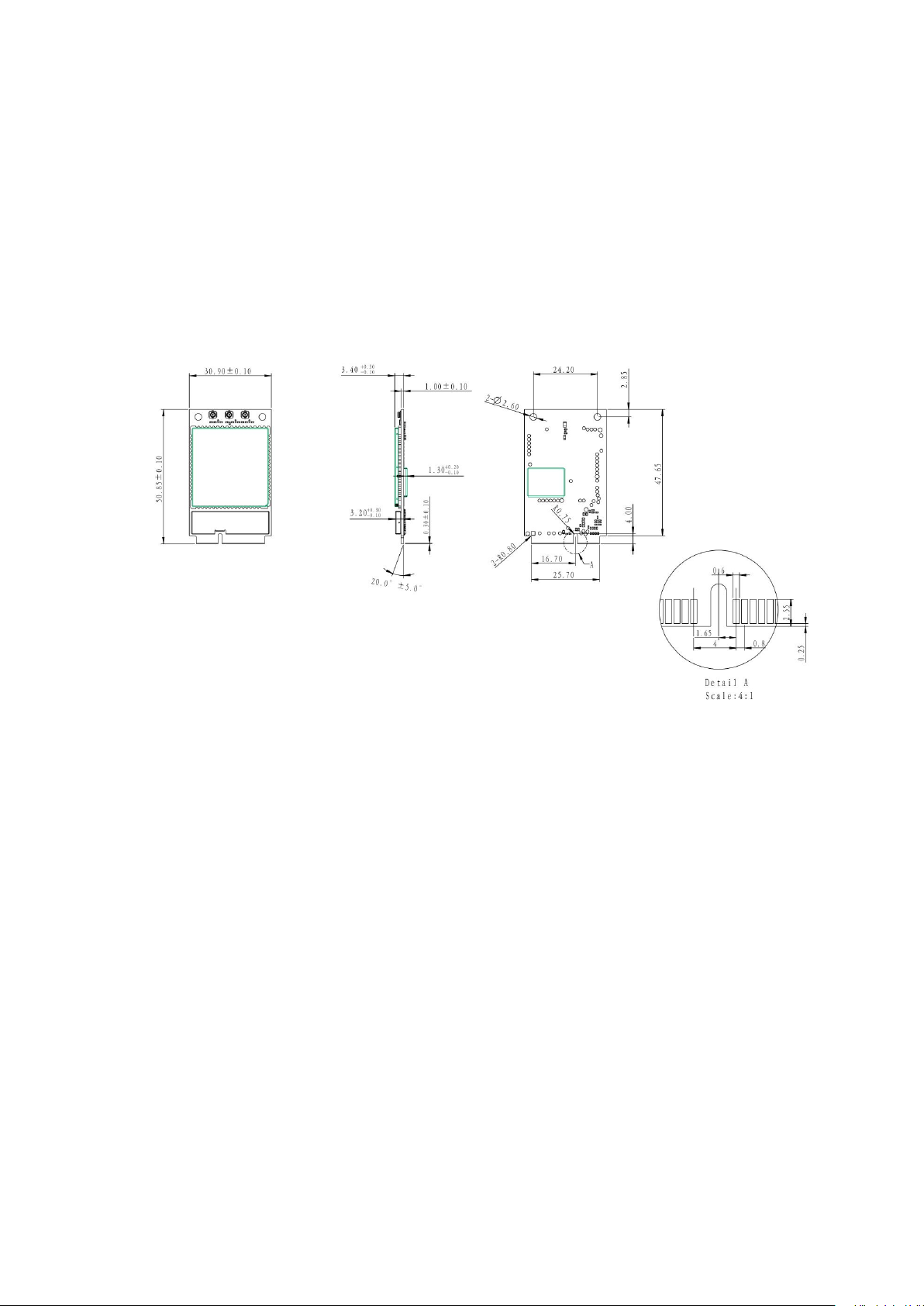
Appendix:Mechanical dimensions of U9507E
The following are Mechanical dimensions of U9507E bottom view, side view and top view. (Unit: mm)
Top View Side View Bottom View
FCC Certification Requirements.
According to the definition of mobile and fixed device is described in Part 2.1091(b), this device is a mobile
device.
And the following conditions must be met:
1. This Modular Approval is limited to OEM installation for mobile and fixed applications only. The antenna
installation and operating configurations of this transmitter, including any applicable source-based time-
averaging duty factor, antenna gain and cable loss must satisfy MPE categorical Exclusion Requirements of
2.1091.
2. The EUT is a mobile device; maintain at least a 20 cm separation between the EUT and the user’s body
Page 30 of 32
Page 31

and must not transmit simultaneously with any other antenna or transmitter.
3.A label with the following statements must be attached to the host end product: This device contains FCC
ID: XHZU9507E.
4.To comply with FCC regulations limiting both maximum RF output power and human exposure to RF
radiation, maximum antenna gain (including cable loss) must not exceed:
❒ WCDMA Band 5 (Tx: 824 MHz ~ 849 MHz): <1dBi
❒ LTE Band 5 (Tx: 824 MHz ~ 849 MHz): <1dBi
❒ LTE Band 7(Tx: 2500 MHz ~ 2570 MHz): <5dBi
5. This module must not transmit simultaneously with any other antenna or transmitter
6. The host end product must include a user manual that clearly defines operating requirements and
conditions that must be observed to ensure compliance with current FCC RF exposure guidelines.
For portable devices, in addition to the conditions 3 through 6 described above, a separate approval is
required to satisfy the SAR requirements of FCC Part 2.1093
If the device is used for other equipment that separate approval is required for all other operating
configurations, including portable configurations with respect to 2.1093 and different antenna
configurations.
For this device, OEM integrators must be provided with labeling instructions of finished products. Please
refer to KDB784748 D01 v07, section 8. Page 6/7 last two paragraphs:
A certified modular has the option to use a permanently affixed label, or an electronic label. For a
permanently affixed label, the module must be labeled with an FCC ID - Section 2.926 (see 2.2
Certification (labeling requirements) above). The OEM manual must provide clear instructions explaining
to the OEM the labeling requirements, options and OEM user manual instructions that are required (see
next paragraph).
For a host using a certified modular with a standard fixed label, if (1) the module’s FCC ID is not visible
when installed in the host, or (2) if the host is marketed so that end users do not have straightforward
commonly used methods for access to remove the module so that the FCC ID of the module is visible; then
Page 31 of 32
Page 32

an additional permanent label referring to the enclosed module:“Contains Transmitter Module FCC ID:
XHZU9507E” or “Contains FCC ID: XHZU9507E” must be used. The host OEM user manual must also
contain clear instructions on how end users can find and/or access the module and the FCC ID.
The final host / module combination may also need to be evaluated against the FCC Part 15B criteria for
unintentional radiators in order to be properly authorized for operation as a Part 15 digital device.
The user’s manual or instruction manual for an intentional or unintentional radiator shall caution the user
that changes or modifications not expressly approved by the party responsible for compliance could void
the user's authority to operate the equipment. In cases where the manual is provided only in a form other
than paper, such as on a computer disk or over the Internet, the information required by this section may be
included in the manual in that alternative form, provided the user can reasonably be expected to have the
capability to access information in that form.
This device complies with part 15 of the FCC Rules. Operation is subject to the following two conditions: (1)
This device may not cause harmful interference, and (2) this device must accept any interference received,
including interference that may cause undesired operation.
Changes or modifications not expressly approved by the manufacturer could void the user’s authority to
operate the equipment.
To ensure compliance with all non-transmitter functions the host manufacturer is responsible for ensuring
compliance with the module(s) installed and fully operational. For example, if a host was previously
authorized as an unintentional radiator under the Declaration of Conformity procedure without a transmitter
certified module and a module is added, the host manufacturer is responsible for ensuring that the after the
module is installed and operational the host continues to be compliant with the Part 15B unintentional radiator
requirements.
Page 32 of 32
 Loading...