

Page 1
Page 1 of 6
FF
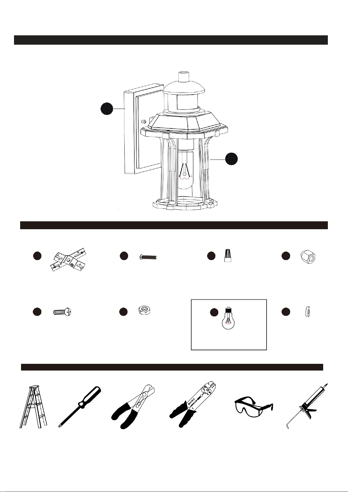
Bulb (included)
AACCEE
GG
BBDDHH
INSTALLATION MANUAL | MANUEL D’INSTALLATION | MANUAL DE INSTALACIÓN
A
B
Ladder
Échelle
Escalera
Screwdriver
Tournevis
Destornillador
Wire cutter Coupe-
fils Cortador de
cables
Wire stripper
Pince à dénuder
Pelacables
Safety goggles
Lunettes de sécurité
Anteojos de seguridad
Silicone
Silicone
Silicona
PACKAGE CONTENTS
0308-WD
0308M-WD
SUPPLIED HARDWARE LIST/
X1 X2 X3 X2
X2 X4 X2
QUINCAILLERIE FOURNIE/
CONTENIDO DE HARDWARE
TOOLS REQUIRED (not supplied)/ OUTILS REQUIS (non fournis)/ HERRAMIENTAS NECESARIAS (no incluido)
Page 2
Page 2 of 6
WARNINGS AND CAUTIONS /AVERTISSEMENTS ET MISES EN GARDE /ADVERTENCIAS Y PRECAUCIONES
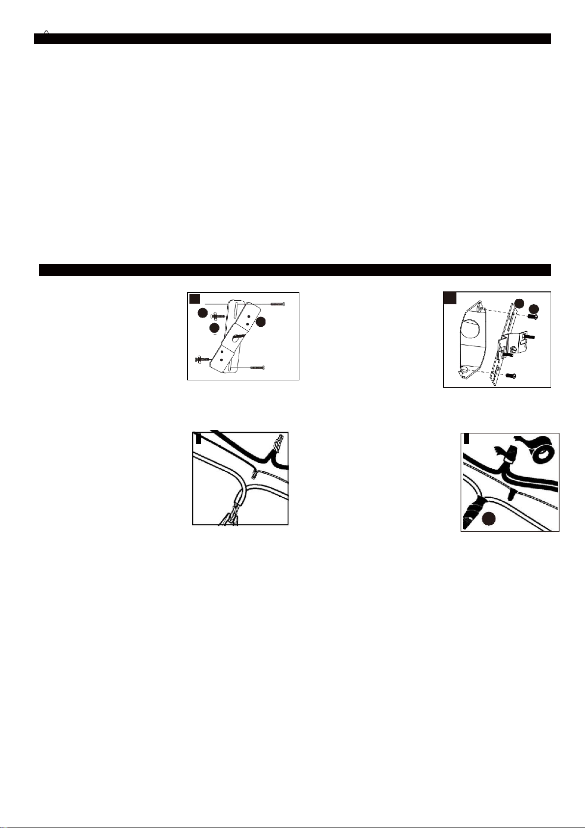
1. Fix the support screws(CC)
with hex nuts(DD) onto the
mounting strip(AA).
1. Ponga los niple(CC) Con
las tuercas(DD) sobre la
barra de montaje(AA).
1. Fixez la tige(CC) avec
l'écrou hexagonal (DD) sur
la bandelette de support(AA).
3.Strip 1/2 in. of insulation from wire
ends. Twist stripped ends together
with pliers black to black (power)
and withe to white (neutral).
Attach copper wire to ground wire.
Helpful Hint:
If necessary, attach copper
ground wire to grounded jnction
box.
3.Dénuder 1,3 cm(1/2 po) d’isolant des extrémités du fil.
Attacher les extrémités dénudées ensemble avec des
pinces noir à noir (courant) et blanc à blanc (neutre).
Attacher le fil en cuiver au fil à la terre.
Conseil utile:
Si nécessaire, attacher le fil de terre en cuiver à la
boîte de connexion à la terre.
3.Pele 1,3 cm del aislamiento en el extremo de los
cables. Retuerza juntos los extremos pelados con las
pinzas negro a negro (activo) y blanco a blanco
(neutral). Fije el cable de cobre al cable de tierra.
Consejo útil:
Si fuese necesario, fije el cable de cobre de conexión
a tierra a la caja terminal conectada a tierra.
2. Attach mounting strip(AA)
to junction box using outlet
box screws(BB).
2. Conecte la barra de
montaje(AA) a la caja de
salida usando los tornillos
de montaje(BB).
2. Fixez la bandelette de
support(AA) à la boíte à
bornes en utilisant les vis
de la boîte de sortie(BB).
4. Attach wire nuts (EE). Tape nuts
(EE) and wires together with
electrical tape.
4. Acttacher les capuchons de
connexion (EE). Attacher les
capuchons (EE) et les fils
ensemble avec du ruban isolant.
4.
Coloque los empalmes plàsticos
(EE). Encinte los empalmes (EE)
y los alambres juntos con cinta
aislante.
1
CC
AA
DD
3
2
AA
BB
4
EE
●
TURN OFF ELECTRICITY at main fuse box (or circuit breaker box) before beginning installation by switching circuit
breaker off or removing fuse.
●
CONSULT A QUALIFIED ELECTRICIAN TO ENSURE CORRECT BRANCH CIRCUIT CONDUCTOR.
●
If in doubt about electrical installation, consult a licensed electrician.
●
ÉTEINDRE L'ÉLECTRICITÉ au coffret à fusibles principal (ou au disjoncteur) avant de commencer l’installation en
éteignant le disjoncteur ou en enlevant un fusible.
●
VOIR UN ÉLECTRICIEN QUALIFIÉ POUR GARANTIR UN CONDUCTUR DE PROTECTION DIVISIONNAIRE
CORRECT.
●
En cas de doute sur l’installation électrique, voir un électricien licencié.
●
DESCONECTE LA ELECTRICIDAD en la caja de fusibles (o en la caja de interruptor de circuitos) apagando el
interruptor de circuitos o retirando el fusible.
●
CONSULTE A UN ELECTRICISTA CALIFICADO PARA ASEGURAR EL CONDUCTOR DE CIRCUITO
DERIVADO ADECUADO.
●
Si tiene duda sobre la instalación eléctrica, consulte a un electricista cerfificado.
INSTALLATION/ INSTALLATION/ INSTALACIÓN
Page 3
Page 3 of 6
Fig.2
Top Knob
Top Cover
Adjustable
Knob
See Detail A
Fig.1
Top Knob
Top Cover
Sensor
Lens
Fig.3
Top Knob
Top Cover
Fig.4
INSTALLATION/ INSTALLATION/ INSTALACIÓN
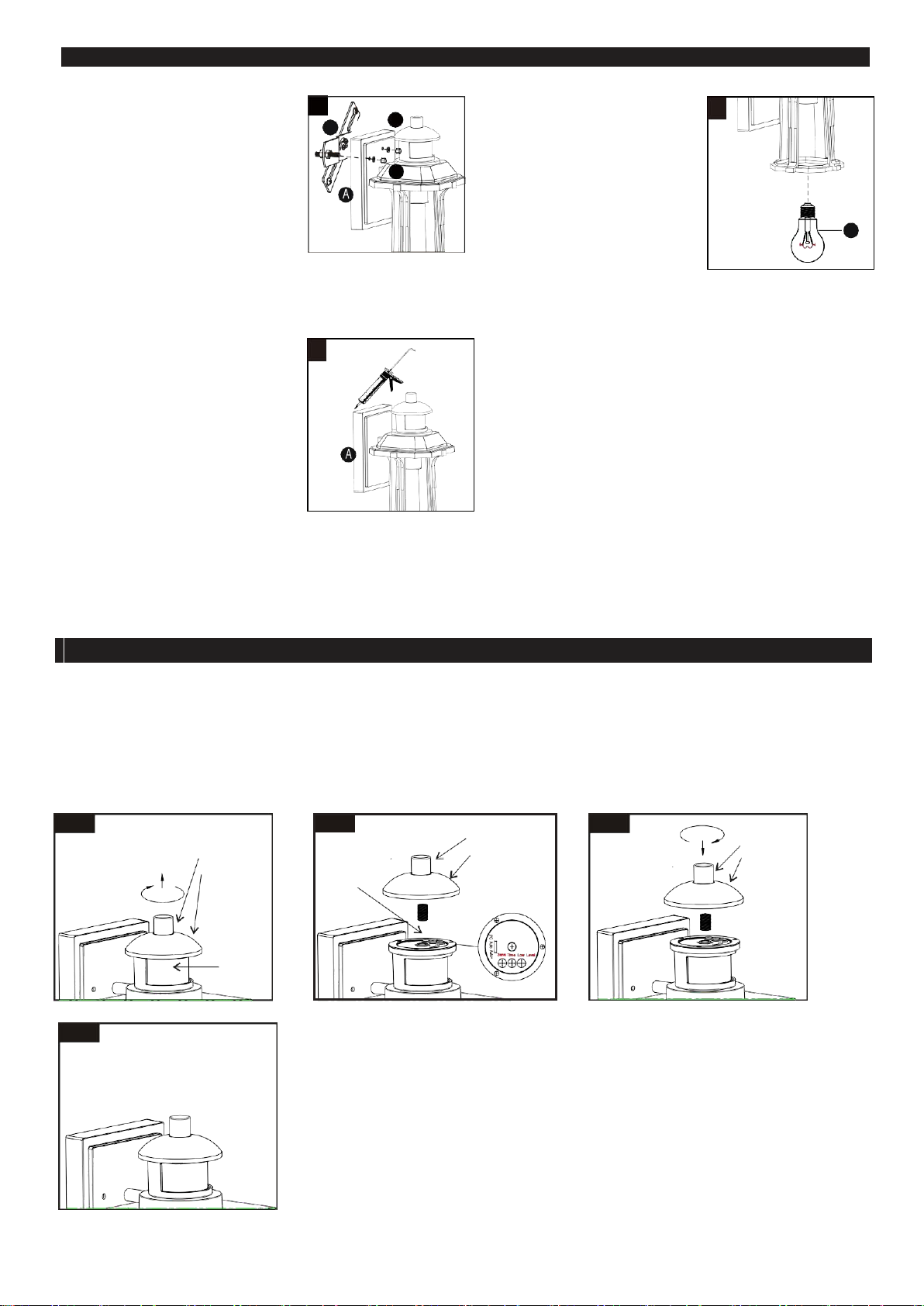
5.
Install the back plate (A) to the
mounting plate (AA) with bolts
(GG).Strongly tighten the bolts.
5. Installer la plaque arrière (A) à la
plaque de montage (AA) avec les
boulons (GG). Serrez fermement
les boulons.
5. Instalar la placa posterior (A) a la
placa de montaje (AA) con los
pernos (GG). Apretar fuertemente
los pernos.
7. Apply a clear silicone water
sealant around the outside
perimeter of the back plate (A).
7. Appliquez un joint de silicone
transparent autour du périmètre
extérieur de la plaque
arrière (A).
7. La aplicación de un sellador al
agua de silicona transparente
alrededor del perímetro exterior
de la placa posterior (A).
6. Install light bulbs(FF). Use only
bulbs of the specified type and
maximum rated wattage or
less.
6. Installer les ampoules(FF).
N’utiliser que les ampoules du
type spécifié et ne dépassant
pas le watta ge spécifié.
6. Coloque las bombillas(FF) .
Use solo bombillas del tipo y
vataje especificado o de un
vataje inferior.
5
HH
AA
GG
7
6
FF
FUNCTION AND OPERATION
Turn on the light ,waiting for 30 seconds to allow the sensor to warm up , then select one function .
Rrmark :
1.
2.
The Position of Adjustable Knob
Warm time long or short is according to adjust time .
Factry setting is AUTO mode ( 60 seconds,the preset maximum induction distance is 10 meters.)
Page 4
Page4of 6
FUNCTION AND OPERATION (continued)
Fig.5
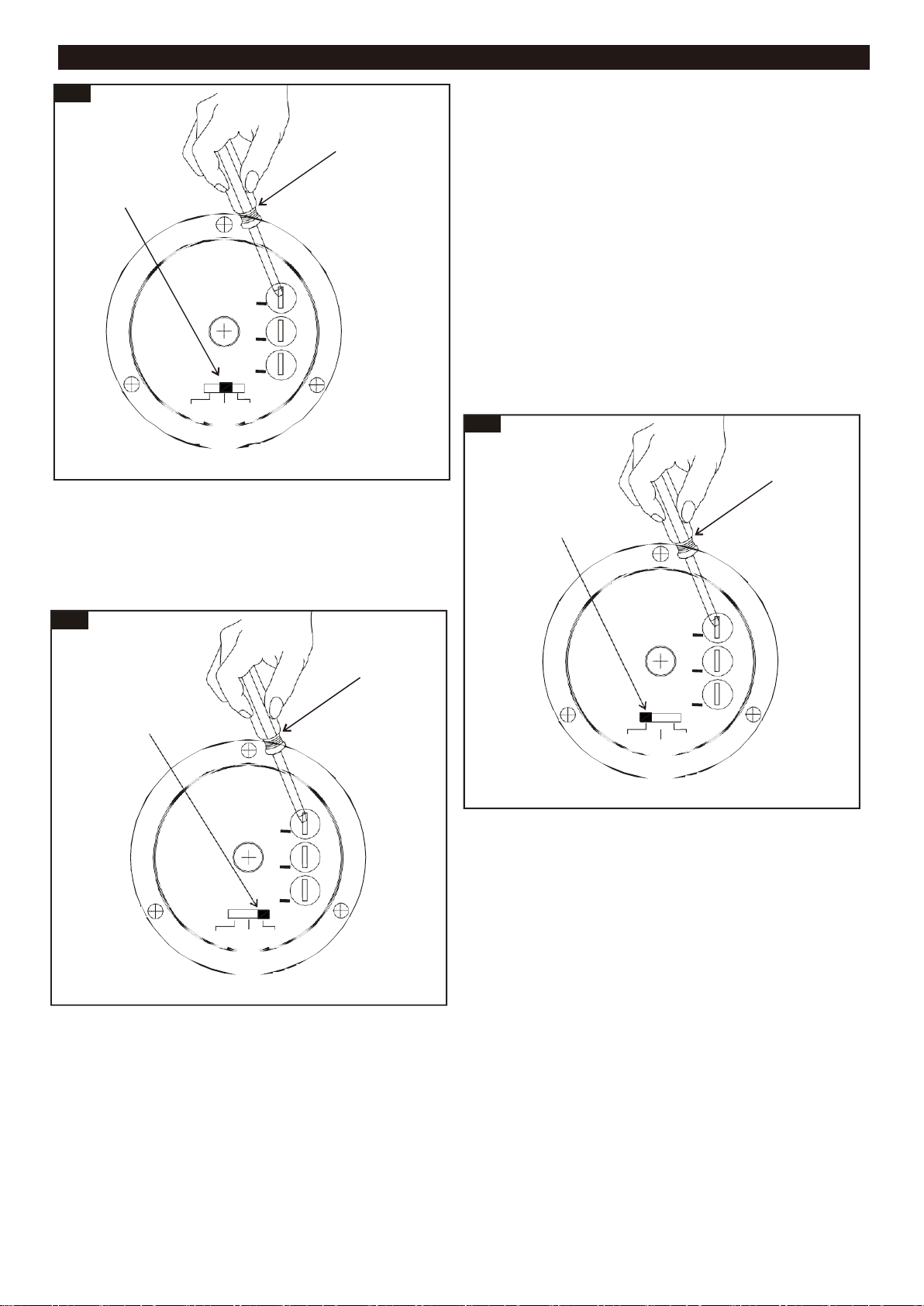
Flathead Screwdriver
(not included)
Slide Switch (Set to AUTO
)
+
+
+
PC A
uto Aut o
+
Detail A View
Fig.6
Flathead Screwdriver
(not included)
Slide Switch (Set to PC)
+
+
+
PC A
uto Aut o
+
Detail A View
Low
Level
Fig.7
Flathead Screwdriver
(
not included
)
Slide Switch (Set to AUTO+ )
+
+
+
PC A
uto Aut o
+
Detail A View
Time
Sens
Low
Level
Time
Low
Level
Sens
Time
Sens
PC (See Fig.6):
A. Day time off .At dusk light on.
Other function is out of work.
AUTO(See Fig.5
A.
Day time off. At dusk When human body activity is
):
sensed, high brightness (100%). When the person is
stationary or leaves the set induction distance, the light
will continue to the preset time (20-180 seconds) and
then turn off. The original setting time is (60 seconds).
B.
(TIME): Turn clockwise to increase, and counterclockwise
rotation reduces. Please use a one-word screwdriver.
Turn clockwise for 1/4 turn around , and the lighting time
will be increased about 60 seconds. The maximum is
180 seconds.
C.(SENS): Clockwise Adjust in time to increase or
Counterclockwise rotation reduces, the preset maximum
induction distance is 10 meters.
D. (LOW LEVEL): This function is out of work.
E. The operating temperature is -7°F ~95°F.
AUTO+ (See Fig.7):
A.
Day time off .At dusk low brightness (Low level is
0%-50% to be manually adjusted) will automatically turn
on. When human body activity is sensed, high
brightness (100%). When the person is stationary or
leaves the set induction distance, the high brightness
(100%) will continue to the preset time (20-180 seconds)
and then turn to the low brightness (Low level setting 0%50%). The original setting time for high brightness is (60
seconds).
B.(TIME): Turn clockwise to increase, and counterclockwise rotation reduces. Please use a one-word screwdriver.
Turn clockwise for 1/4 turn around , and the lighting time will be increased about 60 seconds. The maximum is 180
seconds.
C.(SENS): Clockwise Adjust in time to increase or Counterclockwise rotation reduces, the preset maximum induction
distance is 10 meters.
D.
(LOW LEVEL): When clockwise adjusted to increase or Counterclockwise rotation reduces.
E.
Incandescent bulbs are fine . LED bulbs must be dimmable.
F.
The operating temperature is -7°F ~95°F.
Page 5
Page5of 6
FUNCTION AND OPERATION (continued)
SYMPTOM
DAY/NIGHT
POSSIBLE CAUSE
SOLUTION
If the light
isn’t on
Day
Light only work on night.
Keep of all sensor for testing.
Night
Wall switch or circuit breaker is off.
Turn on wall switch or circuit breaker.
Light bulb may be burned out.
Test the light bulb on normal working light fixture.
Light bulb is loose.
Tighten the light bulb.
Incorrect or loose wire connections.
Check wire connections.
Too much sunlight is shining onto
sensor in the early evening.
Relocate fixture away from western facing wall.
Too much light is shining onto
sensor due to another light source,
such as a street lamp or other light
fixture.
Eliminate or turn off other light source, block other
light source from shining onto sensor, or relocate
fixture.
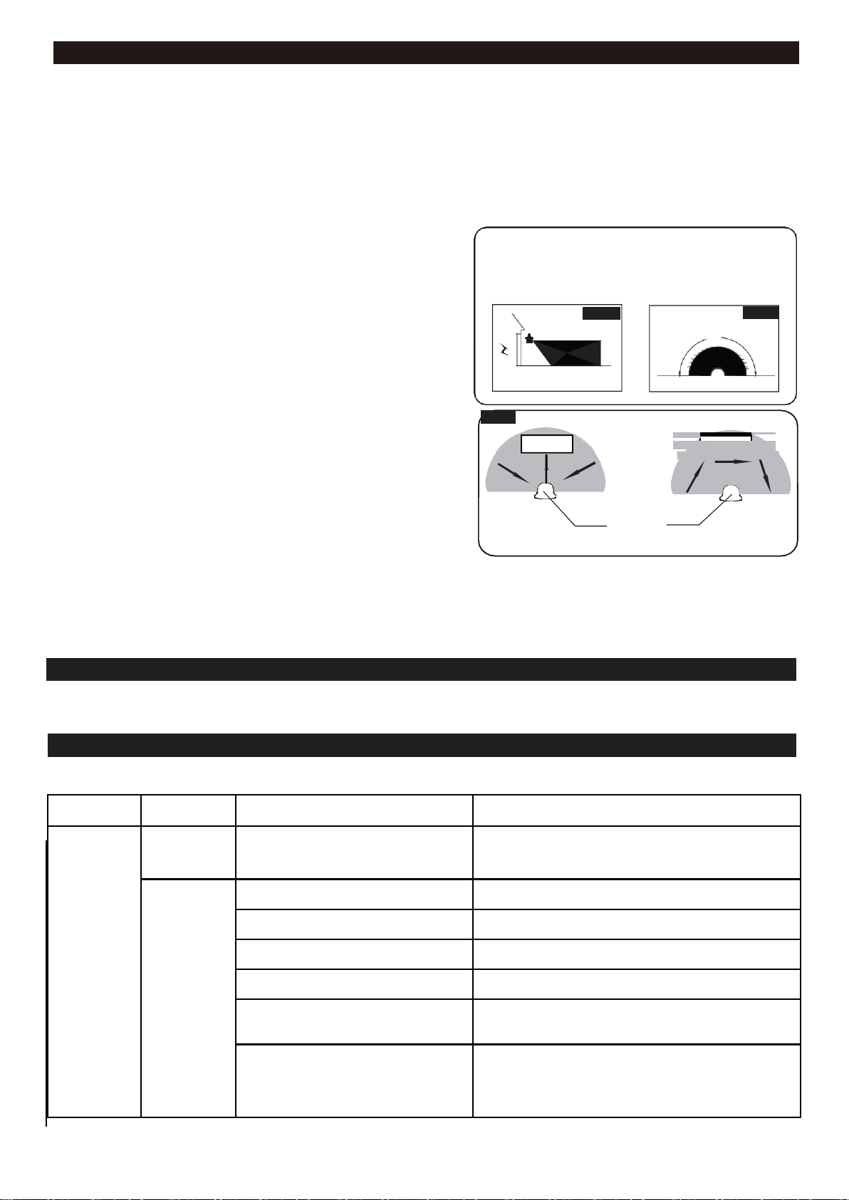
Where you install your lantern is important:
Be sure the light is mounted straight on the wall;
otherwise, the detection distance may be limited.
Fig.8
Fig. 9
10`
180˚
6`
5`
40`
Fig. 10
Least sensitivity
Sensor
Most sensitivity
Motion
Motion
NOTE:
1.
The sensitivity of the motion sensor will increase as the
environmental temperature gets colder. For best performance,
gently clean the lens with a soft cloth every 1 or 2 months to
ensure maximum sensitivity.
2.
The magnitude of adjustment for sensitivity and time may not be
precisely proportionate to the amount when the knob is turned.
3.
When installed at a height of 6.5 feet, at 77 degrees Fahrenheit,
the light will provide a maximum detection distance of 40 feet
and detection range of 140 degrees. (See Fig.8 Fig.9)
4.
The sensor will be more sensitive to motion across its
detection path than motion directly towards it. (See Fig.10)
5.
To reduce possible nuisances, do not mount the fixture
near a heat source like an air conditioner, vent or furnace
exhaust, or in a direction facing any reflecting object or
other light source.
CARE AND MAINTENANCE
●
To clean, turn off and wipe with a damp, non-abrasive cloth.
TROUBLESHOOTING
Refer to following information to solve your problems.
Page 6

Page6of 6
SYMPTOM
DAY/NIGHT
POSSIBLE CAUSE
SOLUTION
If the light
stays on
Day
The fixture may be installed in
shaded area.
Only need to relocate fixture.
On cloudy or overcast days, the light
may stay on longer than anticipated.
No corrective action needed.
Night
Still in self-testing
Turn off the light, then turn it on after 5 seconds.
False triggering caused by a heat
source, such as a heater, dryer vent,
or heated swimming pool.
Eliminate heatsource or relocate fixture.
The switch is not set in any mode.
Slide it again to the mode you want.
If the light
is blinking
Night
The bulb is non-dimmable or the
quality of light bulb is not good.
Use another normal incandescent lamp to confirm
if the light function is normal, otherwise change the
bulb.
Passing cars and reflective objects
interfere with the sensor.
Relocate fixture.
The light
comes on for
no apparent
reason
Night
Street or sidewalk traffic is triggering
motion sensor.
Adjust the "Sens" knob to reduce the sensitivity.
False triggering caused by a heat
source, such as a heater, dryer vent,
or heated swimming pool.
Eliminate heat source or relocate fixture.
If unable to fix any of the above issues, please consult a certified electrician.
 Loading...