

Page 1
IP Sharing Router
User Manual
Version 2.0
Date: Sep. 25, 2009
Page 2

IP Sharing Router
- 2 -
FCC Certifications
Federal Communication Commission Interference Statement
This equipment has been tested and found to comply with the limits for a Class B digital device, pursuant
to Part 15 of the FCC Rules. These limits are designed to provide reasonable protection against harmful
interference in a residential installation. This equipment generates, uses and can radiate radio frequency
energy and, if not installed and used in accordance with the instructions, may cause harmful interference
to radio communications. However, there is no guarantee that interference will not occur in a particular
installation. If this equipment does cause harmful interference to radio or television reception, which can
be determined by turning the equipment off and on, the user is encouraged to try to correct the
interference by one of the following measures:
-Reorient or relocate the receiving antenna.
-Increase the separation between the equipment and receiver.
-Connect the equipment into an outlet on a circuit different from that to which the receiver is connected.
-Consult the dealer or an experienced radio/TV technician for help.
This device complies with Part 15 of the FCC Rules. Operation is subject to the following two conditions:
(1) This device may not cause harmful interference, and (2) this device must accept any interference
received, including interference that may cause undesired operation.
FCC Caution: Any changes or modifications not expressly approved by the party responsible for
compliance could void the user's authority to operate this equipment.
CE Mark Warning
This equipment complies with the requirements relating to electromagnetic compatibility, EN 55022 class
B for ITE, the essential protection requirement of Council Directive 2004/108/EC on the approximation of
the laws of the Member States relating to electromagnetic compatibility.
Company has an on-going policy of upgrading its products and it may be possible that information in this
document is not up-to-date. Please check with your local distributors for the latest information. No part of
this document can be copied or reproduced in any form without written consent from the company.
Trademarks:
All trade names and trademarks are the properties of their respective companies.
Copyright © 2009, All Rights Reserved.
Page 3

IP Sharing Router
- 3 -
Content
Unpacking Information................................................................................................................................5
Chapter 1 Introduction.............................................................................................................................6
1.1 General Description......................................................................................................................6
1.2 Key Features ................................................................................................................................6
1.3 The Front Panel............................................................................................................................7
1.4 The Right Panel............................................................................................................................8
1.5 The Rear Panel.............................................................................................................................8
1.6 Connecting this Router to your network........................................................................................9
1.7 Application Scenario .....................................................................................................................9
Chapter 2 Quick Installation Guide........................................................................................................10
2.1 Configure PC..............................................................................................................................10
2.2 Login...........................................................................................................................................14
2.3 Quick Setup................................................................................................................................15
Chapter 3 Configuring the Router .........................................................................................................19
3.1 Admin..........................................................................................................................................19
3.1.1 Management....................................................................................................................19
3.1.2 System Settings...............................................................................................................20
3.1.3 Firmware Upgrade...........................................................................................................21
3.1.4 Configuration....................................................................................................................21
3.1.5 Tools.................................................................................................................................21
3.1.6 Language.........................................................................................................................22
3.1.7 Log Settings.....................................................................................................................22
3.1.8 Logout..............................................................................................................................22
3.2 WAN............................................................................................................................................23
3.3 LAN.............................................................................................................................................32
3.3.1 LAN Settings....................................................................................................................32
3.3.2 DHCP Client List..............................................................................................................33
3.4 NAT.............................................................................................................................................34
3.4.1 Virtual Server...................................................................................................................34
3.4.2 Port Triggering.................................................................................................................35
3.4.3 Port Mapping....................................................................................................................36
3.4.4 Passthrough.....................................................................................................................38
3.4.5 DMZ.................................................................................................................................39
3.5 Firewall .......................................................................................................................................40
3.5.1 Firewall Options...............................................................................................................40
3.5.2 Client Filtering..................................................................................................................41
3.5.3 URL Filtering....................................................................................................................42
3.5.4 MAC Filtering...................................................................................................................42
3.6 Routing .......................................................................................................................................44
Page 4

IP Sharing Router
- 4 -
3.6.1 Routing Table...................................................................................................................44
3.6.2 Static Routing...................................................................................................................44
3.6.3 Dynamic Routing..............................................................................................................45
3.7 QoS.............................................................................................................................................47
3.8 Misc ............................................................................................................................................48
3.8.1 UPnP................................................................................................................................48
3.8.2 DDNS...............................................................................................................................49
3.9 Status..........................................................................................................................................50
3.9.1 Status...............................................................................................................................50
3.9.2 Log...................................................................................................................................50
Appendix A: Specifications .......................................................................................................................52
Appendix B: Glossary...............................................................................................................................53
Page 5

IP Sharing Router
- 5 -
Unpacking Information
Thank you for purchasing the product. Before you start, please check all the contents of this package.
The product package should include the following:
1. One IP Sharing Router
2. One Power Adapter
3. One resource CD, including: User’s Manual
Note:
Make sure that the package contains the above items. If any of the listed items are damaged or missing,
please contact with your distributor.
Conventions
The Router mentioned in this guide stands for IP Sharing Router without any explanation.
Page 6

IP Sharing Router
- 6 -
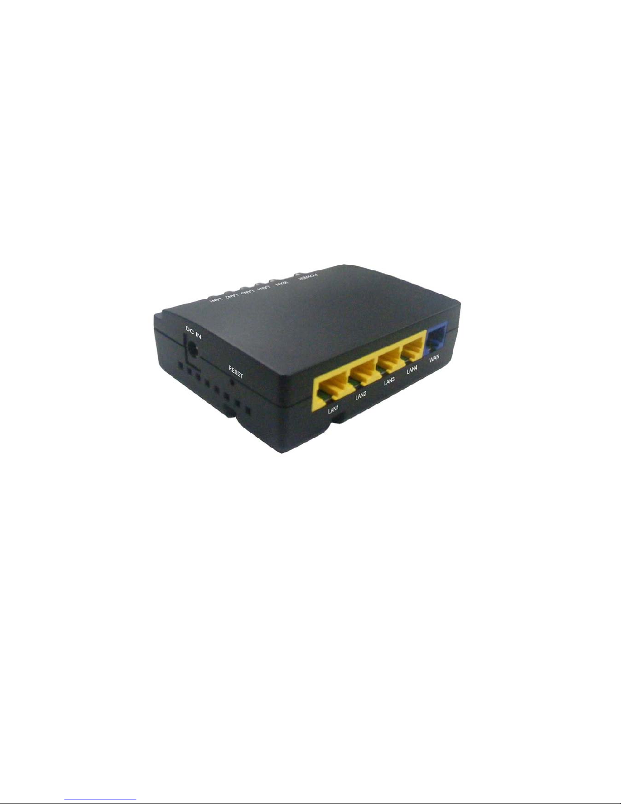
Chapter 1 Introduction
With the excellent circuit design and high quality production, we guarantee its high performance, great
stability and easy to use.
This product is a complete plug-and-play solution. With standard Ethernet interface, it can be directly
connected to any 10M/100M Ethernet devices, support Auto-MDI/MDIX.
1.1 General Description
High Performance
It provides the most cost-effective solution for IP sharing router. Among these Ethernet ports, four ports
are used as LAN ports and one as WAN ports. Its hardware based IGMP snooping can support the
real-time multimedia application without the intervention of CPU. The switch engine provides rich
functions to meet the requirement of future applications,
Greater Range
With multiple functions, high-reliability, and high-security, it widely meets enterprise, organ, Internet cafe,
broadband community, and school networks new and changing requirements. Additionally, it provides a
friendly configuration interface for easy using and perfect setting up.
Strong Security Function
It features much more advanced security functions, such as NAT, Firewall. Moreover, it provides strong
attack and defense function and supports internal and external attack precaution. It is especially effective
in the prevention of DoS Attacks----ICMP Flood, UDP Flood, SYN Flood, Ping of Death, Land Attack etc.
1.2 Key Features
Provides 4*10/100 Mbps Ethernet port for LAN, 1*10/100 Mbps Ethernet port for WAN
Support 1K MAC addresses table
Support Auto MDI/MDIX
Provide 512 KB Flash, 2 MB SDRAM
UI Language provides English and Traditional Chinese.
WAN support Static IP, DHCP client, PPPoE, PPTP,L2TP, BigPond
Support Virtual Server, DMZ, DoS, UPnP, DDNS, QoS.
Support IP filter, MAC Filter, URL filter.
Support Static Routing, Dynamic Routing.
Support VPN Passthrough, Netmeeting Passthrough.
EMI Certification : FCC, CE, VCCI Class B
Page 7
IP Sharing Router
- 7 -
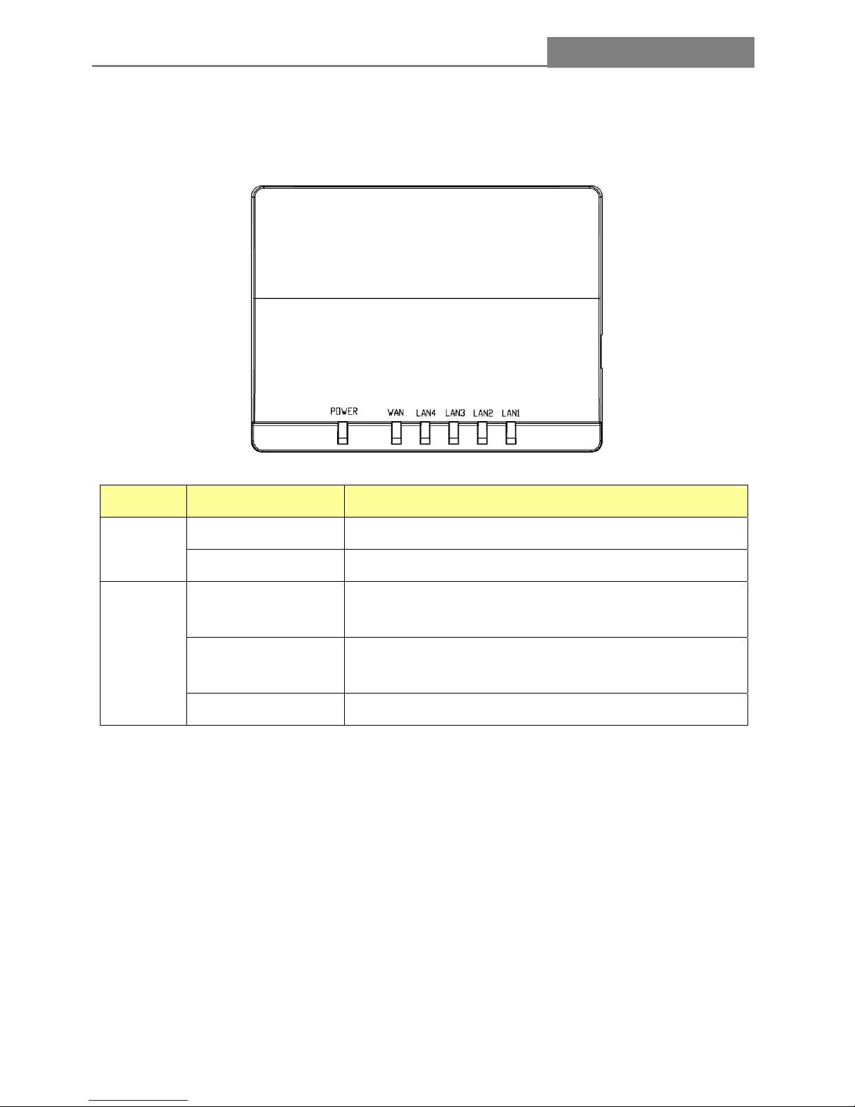
1.3 The Front Panel
The front panel of IP Sharing Router includes one power indicator and five function indicators, as
explained in the following chart.
Name Status Indication
On Power On
Power
Off Power Off
Off
There is no device linked to the corresponding port or the
connection is dropping off.
On
There are devices linked to the corresponding ports but no
data transmitted or received.
WAN /
LAN (1~5)
Blinking Sending or receiving data over corresponding port
Page 8
IP Sharing Router
- 8 -
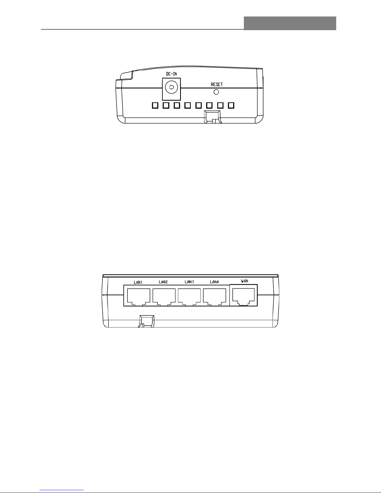
1.4 The Right Panel
z
DC IN
Plug the circle end of the power adapter firmly into the rear panel of the Router, and the other end
put into an electric service outlet then the system is ready.
z
RESET
Push the button for more than 5 seconds and then release it, the system will reset to factory default
setting. In the meantime, system rewrites flash to default value. Approximately 15 seconds later,
the whole system parameters have reset to factory default value. If the process has been
interrupted by any reason (power off), the system will fail. Before performing the process, ensure a
safe operating environment please!
1.5 The Rear Panel
z LAN(1~4): Through these ports, you can connect the Router to your PCs and the other Ethernet
network devices.
z WAN: This WAN port is where you will connect the cable/DSL Modem, or Ethernet
Page 9
IP Sharing Router
- 9 -
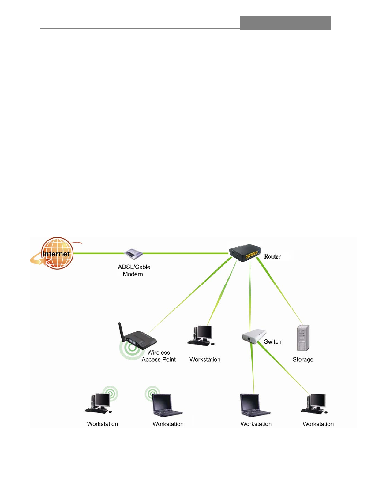
1.6 Connecting this Router to your network
Before you install the router, you should connect your PC to the Internet through your broadband service
successfully. If there is any problem, please contact with your ISP for help. After that, please install the
router according to the following steps. Don’t forget to pull out the power plug and keep your hands dry.
1. Connect the PC(s) and all Switched/Hubs on your LAN to the LAN Ports on the router.
2. Connect the DSL/Cable modem to the WAN port on the router.
3. Connect the AC power adapter to the AC power socket on the router, and the other end into an
electrical outlet. The router will start to work automatically.
4. Power on your PC(s) and Cable/DSL modem.
Note:
Do not use this product near water, for example, in a wet basement or neat a swimming pool. Avoid using
this product during an electrical storm. There may be a remote risk of electric shock from lightning
1.7 Application Scenario
Page 10
IP Sharing Router
- 10 -
Chapter 2 Quick Installation Guide
After connecting the router into your network, you should configure it. This chapter describes how to
configure the basic functions of your router. These procedures only take you a few minutes. You can
access the internet via the router immediately after it has been successfully configured.
2.1 Configure PC
In order to communicate with this Router, you have to configure the IP addresses of your computer to
make it compatible with the device.
Note: The router supports DHCP server and it is enabled as default. Users that configure your IP
address as “Obtain an IP address automatically” may skip the following IP configuration instruction.
The default network setting of the device:
IP address: 192.168.1.1
Subnet Mask: 255.255.255.0
DHCP Server: enable
In the following configuration guide, the IP address “192.168.1.2” is assumed to be your IP address if you
want to specify IP addresses manually. Please DO NOT choose “192.168.1.1” as the IP address. For the
IP address “192.168.1.1“ has been set as the default IP for this device.
The following configuration guide uses windows XP as the presumed operation system.
Procedures to configure IP addresses for your computer
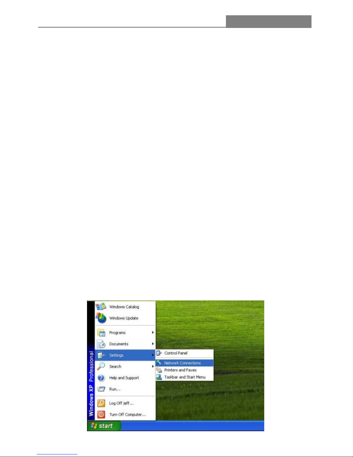
1. If you are in Classic Start menu view, click Start > Settings > Network Connections.
If you are in Start menu view, click Start > Control Panel > Network Connections.
Page 11
IP Sharing Router
- 11 -
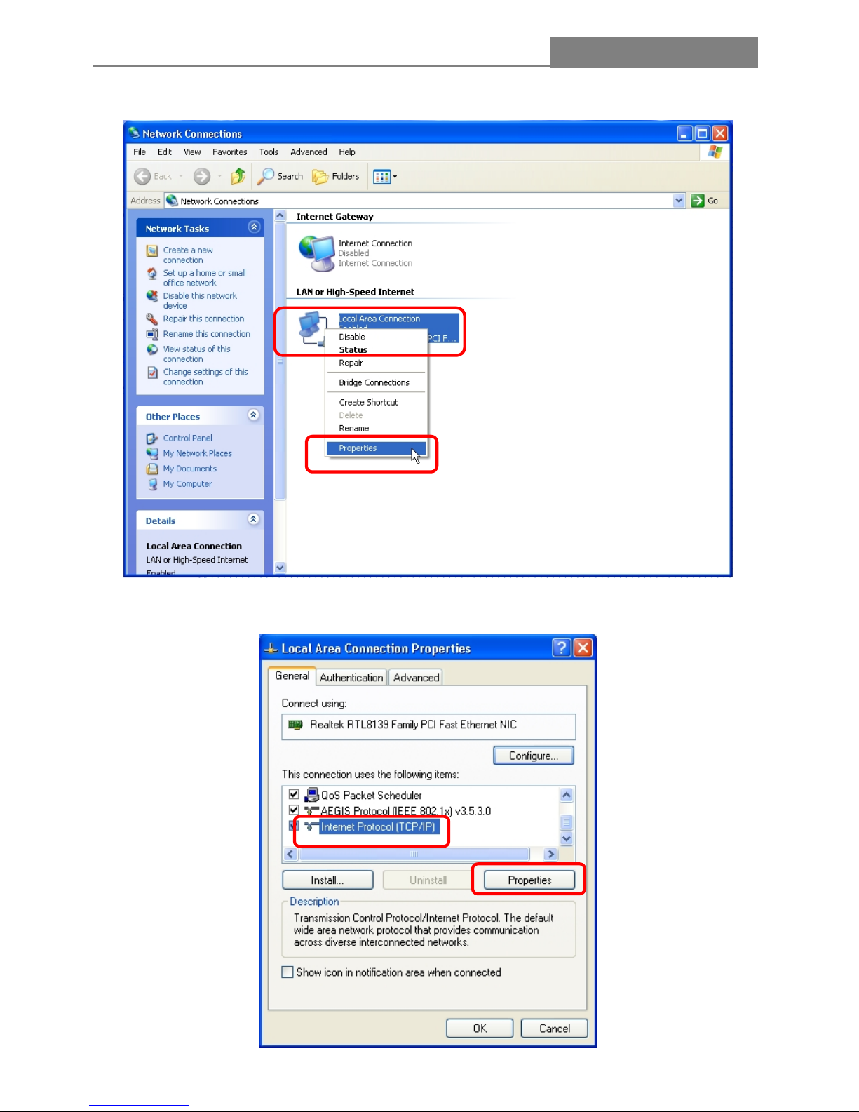
2. Right-click on Local Area Connection item and click on Properties.
3. Choose Internet Protocol (TCP/IP) and click Properties.
Page 12
IP Sharing Router
- 12 -
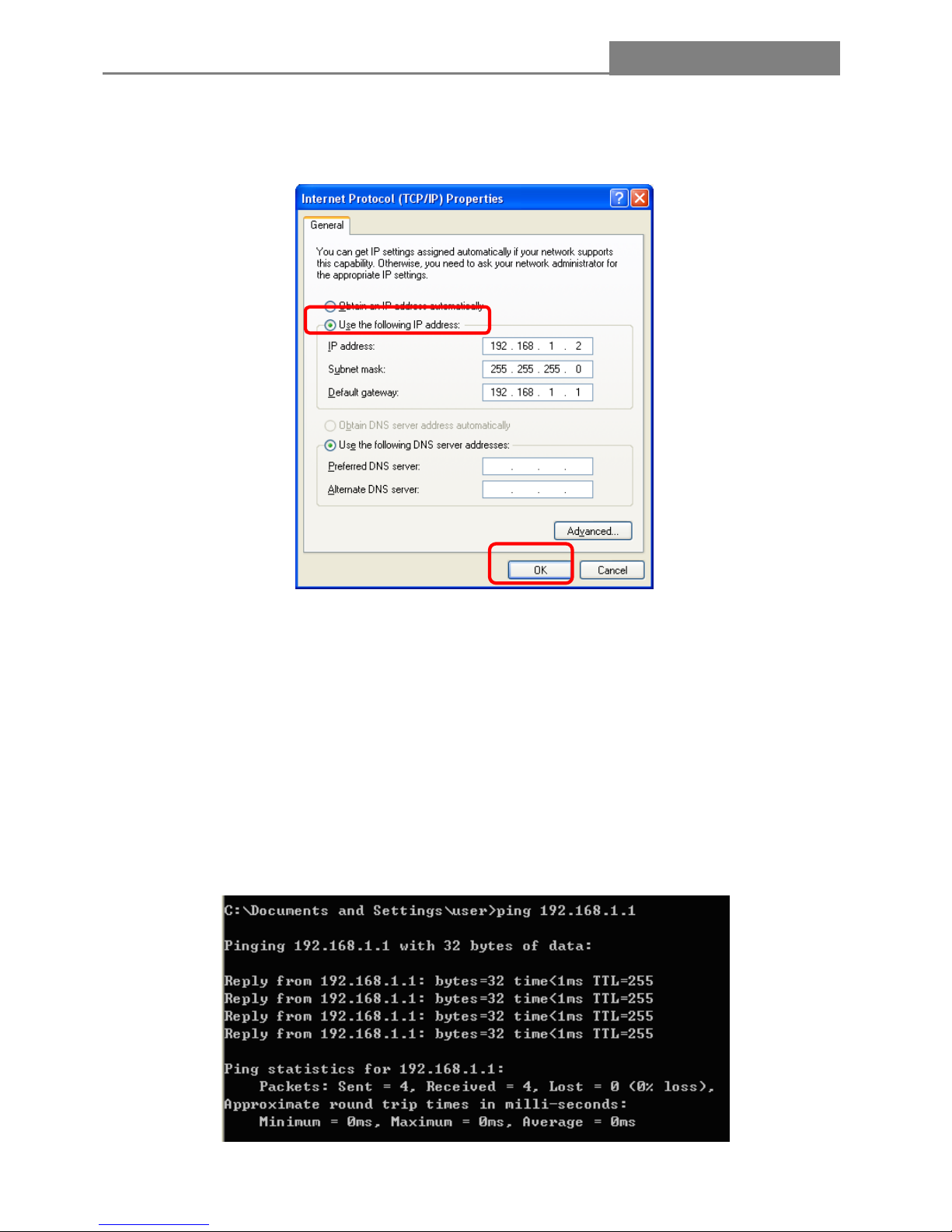
4. You may choose “Obtain an IP address automatically” (recommend) to get IP address automatically
or choose “Use the following IP address” to specify IP addresses manually. Please click the OK button
after your configuration.
Note:
You can configure the PC to get an IP address manually, select “Obtain an IP address automatically” and
“Obtain DNS server address automatically” in the screen above, For Windows 98 OS or earlier, the PC
and router may need to be restarted,
Now, you can run the Ping command in the command prompt to verify the network connection. Please
click the Start menu on your desktop. Select run tab, type cmd in the field, and then type ping
192.168.1.1 on the next screen, and then press Enter.
If the result displayed id similar to the screen below, the connection between your PC and the Router has
been established.
Page 13
IP Sharing Router
- 13 -
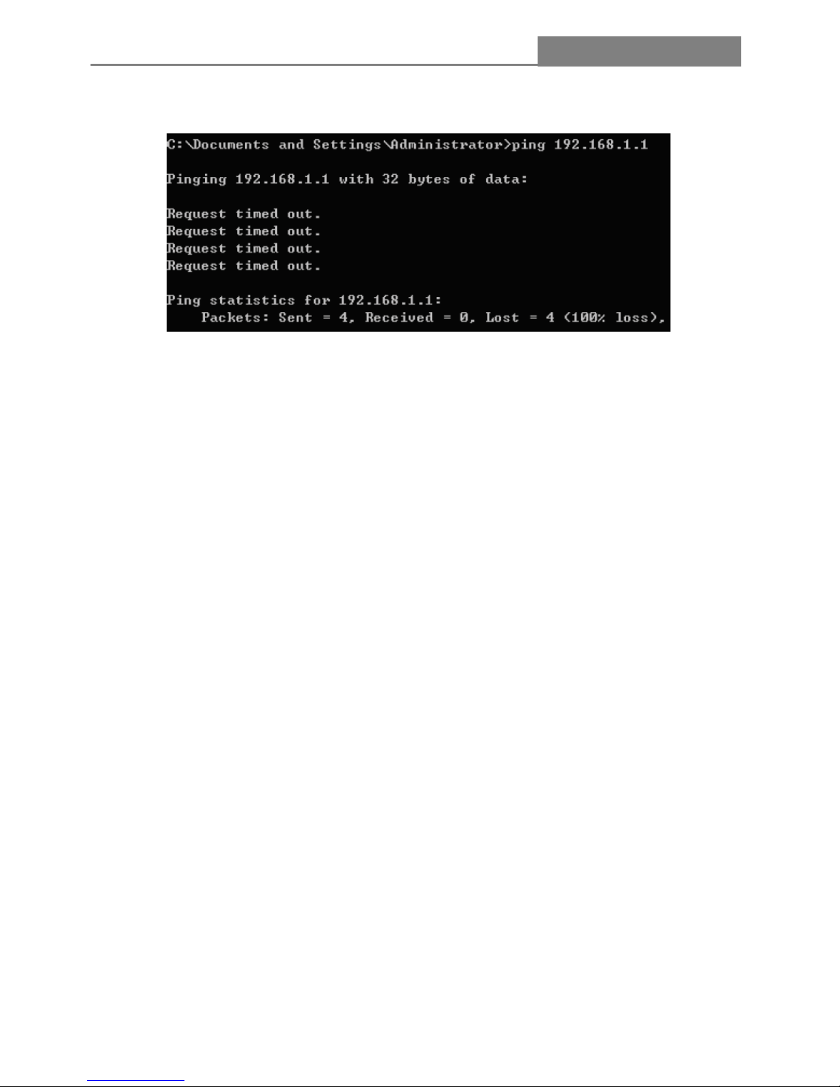
If the result displayed is similar to the screen shown below, it means that your PC has not connected to
the Router.
You can click it follow the steps below:
Note:
Is the connection between your PC and the Router correct?
The LEDs of LAN port which you link to the device and the LEDs on your PC’s adapter should be lit.
Is the TCP/IP configuration for your PC correct?
If the Router’s IP address is 192.168.1.1., you PC’s IP address must be within the range of
192.168.1.2~192.168.1.254, the gateway must be 192.168.1.1.
Page 14
IP Sharing Router
- 14 -
2.2 Login
Once your host PC is properly configured, please proceed as follows to use the Web-based Utility:
1. Open the Internet WEB browser.
2. Type 192.168.1.1 into the URL WEB address location and press Enter.
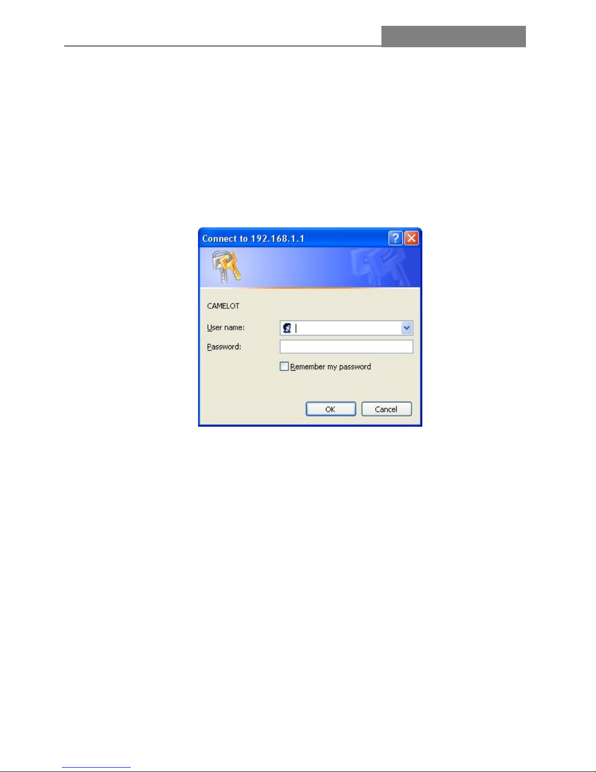
3. The Login window appears.
- Enter admin in the User Name location (default value).
- Enter admin in the Password location (default value).
- Click OK button.
Finally, you access to the Quick Setup screen, then please follow the steps below to complete the Quick
Setup.
Page 15
IP Sharing Router
- 15 -
2.3 Quick Setup
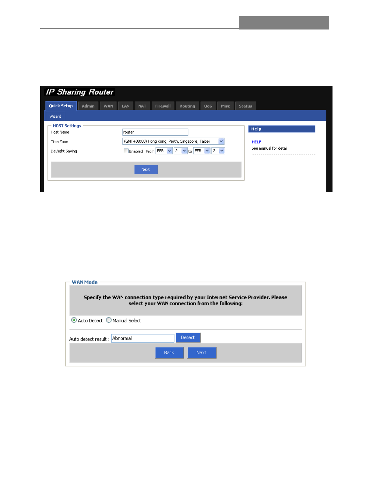
Select the Quick Setup tab on the middle of the main menu and the “Wizard” screen will appear.
1. Host Settings
Enter the host name, select “Time Zone / Daylight Saving”, then click “Next” button
2. WAN Mode
Specify the WAN connection type required by your ISP, please select your WAN connection “Auto Detect
/ Manual Select”
(1) Auto Detect
In this mode, you may only click “Detect” to get the detect result.
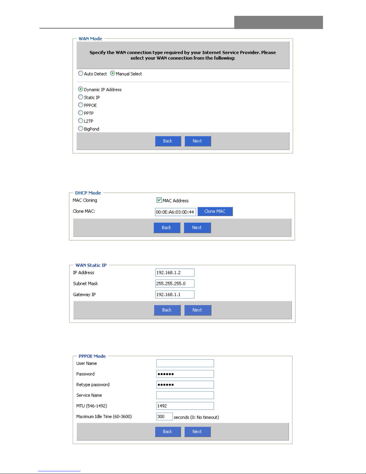
(2) Manual Select
In this mode, the router supports six popular ways to connect to Internet. Please select one compatible
with your ISP.
Page 16
IP Sharing Router
- 16 -
A. If you choose “Dynamic IP Address”, the router will automatically receive the IP parameters from your
ISP without needing to enter any parameters. You will see the screen as the below, select the checkbox of
MAC Address
B. If you choose “WAN Static IP”, you should enter the detailed IP information. Click the “Next” button
C. If you choose “PPPoE”, you will see the screen as the following figure, enter the “User Name &
Password & Retype password & Service Name & MTU & Maximum Idle Time”, and then click the “Next”
Page 17

IP Sharing Router
- 17 -
D. If you choose “PPTP”, you will see the screen as the following figure, enter the “PPTP Account &
PPTP Password & Retype password & Service IP Address & IP Address & Subnet Mask & Gateway &
MTU & Maximum Idle Time”, and then click the “Next”
E. If you choose “L2TP”, you will see the screen as the following figure, enter the “L2TP Account & L2TP
Password & Retype password & Service IP Address & IP Address & Subnet Mask & Gateway & MTU &
Maximum Idle Time”, and then click the “Next”
Page 18

IP Sharing Router
- 18 -
F. If you choose “BigPond”, you will see the screen as the following figure, enter the “BigPond Account &
BigPond Password & Retype password & Authentication Server”, and then click the “Next”
(3) DNS Server
If your ISP gives you one or two DNS address, enter the primary and secondary addresses into the
correct fields. Otherwise, the DNS servers will be assigned dynamically from ISP.
Click Finish to complete the quick installation.
Page 19

IP Sharing Router
- 19 -
Chapter 3 Configuring the Router
This User Guide recommends using the “Quick Installation Guide” for first-time installation. For advanced
users, if you want to know more about this device and make use of its functions adequately, you need to
read this chapter and configure advanced settings through the Web-based Utility.
After your successful login, you can configure and manage the router. There are main menus on the
middle of the Web-based Utility. Submenus will be available after you click one of the main menus. On the
center of the Web-based Utility, you can configure the function. Besides this, you can refer to the help on
the right of Web-based Utility. To apply any settings you have altered on the page, please click the OK
button.
3.1 Admin
Click menu “Admin”, you can see the submenus under the main menu.
3.1.1 Management
In this page, you can change the factory default user name and password of the router in the next screen .
After configuration, click the “OK”
Page 20

IP Sharing Router
- 20 -
Note:
(1) It is strongly recommended that you change the factory user name and password of the router. All
users who try to access the router’s web-based utility will be prompted for the router’s user name and
password.
(2) The new user and password must not include any spaces. Enter the new password twice to co nfirm it.
Remote Management
Select this button to configure the Remote Management function. This feature
allows you to manage your Router from a remote location via the Internet.
Enabled
This is the current address of PC you use when accessing your router from the
Internet. The default IP address is 0.0.0.0. It means this function is disabled. To
enable this function, change the default IP address to another IP address as
desired.
IP Address
The router’s default remote management port number is 8080. For greater
security, you can change the remote management web interface to a custom
port by entering that number in the box provided.
Port
3.1.2 System Settings
Choose menu “Admin—System Settings”, you can configure the time on the screen.
Time
Enter the address of the preferred NTP server.
NTP Server
Select your local time zone from this pull down list.
Time Zone
Select the date range from this pull down list.
Daylight Saving
Name
Host Name
Enter the name of the Router.
Page 21

IP Sharing Router
- 21 -
3.1.3 Firmware Upgrade
You can upgrade the firmware of the device using this tool. Make sure that the firmware you want to use is
saved on the local hard drive of the computer. Click on Browse to search the local hard drive for the
firmware to be used for the update.
3.1.4 Configuration
Choose menu “Configuration”, you can restore the configurations of the Router to factory defaults on the
screen.
Reset default: System configuration is reset to the factory default settings. Default settings are:
"Username: admin", "Password: admin", "IP: 192.168.1.1", "Net mask: 255.255.255.0
Backup Settings: Select the radio button, you can save the current configuration of the Router as a
backup file and restore the configuration via a backup file.
Restore Settings: Select the radio button, then click the Browse button to locate the update file for the
device, or enter the exact path to the Setting file in text box.
3.1.5 Tools
If for any reason the device is not responding correctly, you may want to restart the unit by clicking on the
Reboot button.
Page 22

IP Sharing Router
- 22 -
3.1.6 Language
Specify the language of the device menu. It supports two languages: English, Traditional Chinese.
3.1.7 Log Settings
Not only does the device display the logs of activities and events, it can be setup to send these logs to
another location. The logs can be sent via email to a specific email account.
Remote Log: Select the button to enable Remote Log, and type the IP address of your PC, thus, if your
computer is running to Log Server, you will receive the log information real-in-time once the router has
activities.
Send Email to: Enter the email address the logs will be sent to. Select Email Log and click on “Send” to
send the email.
SMTP Server: Enter the address of the SMTP (Simple Mail Transfer Protocol) server that will be used to
send the logs.
3.1.8 Logout
Logout Account, need to re-type your account and password!!
Page 23

IP Sharing Router
- 23 -
3.2 WAN
The Router provides six connection types for WAN to connect to the Internet, they are “Dynamic IP
Address”, “Static IP”, “PPPoE”, “PPTP”, “L2TP”, and “BigPond”. For configuring the WAN, you should
select the connection type firstly according your needs.
1. Dynamic IP Address
If you aren’t given any login parameters and IP information, please select Dynamic IP, then the router will
automatically get IP parameters from your ISP. Click the OK button to save the IP parameters.
Dynamic IP Address
Enter the IP address of the request.
Request IP Address
The normal MTU (Maximum Transmission Unit) value for most Ethernet
networks is 1500 Bytes. For some ISPs you need to reduce the MTU. But
this is rarely required, and should not be done unless you are sure it is
necessary for your ISP connection.
MTU
Select it or not to configure this parameter.
Static DNS Server
Primary DNS &
If your ISP gives you one or two DNS address, enter the primary and
Page 24

IP Sharing Router
- 24 -
secondary addresses into the correct fields. Otherwise, the DNS servers will
be assigned dynamically from ISP.
Secondary DNS
Select it or not to configure this parameter.
MAC Cloning
This field displays the MAC address of the PC that is managing the router. If
the MAC address is required, you can click the Clone MAC button to copy
the MAC address of the Ethernet Card and replace the WAN MAC address
with this MAC address..
MAC Address
2. Static IP Mode
If your Internet connection requires a static IP address, then your ISP will provide you with a Static IP
Address and Subnet Mask.
WAN Static IP
Enter the IP address in dotted-decimal notation provided by your ISP.
IP Address
Enter the subnet Mask in dotted-decimal notation provided by your ISP, usually
is 255.255.255.0
Subnet Mask
Enter the gateway IP Address in dotted-decimal notation provided by your ISP
Gateway IP
MTU
The normal MTU (Maximum Transmission Unit) value for most Ethernet
networks is 1500 Bytes. For some ISPs you need to reduce the MTU. But this
is rarely required, and should not be done unless you are sure it is necessary
for your ISP connection.
Page 25

IP Sharing Router
- 25 -
Type the DNS address in dotted-decimal notation provided by your ISP.
Primary DNS
Type another DNS address in dotted-decimal notation provided by your ISP if
provided(Optional)
Secondary DNS
Select it or not to configure this parameter.
MAC Cloning
This field displays the MAC address of the PC that is managing the router. If
the MAC address is required, you can click the Clone MAC button to copy the
MAC address of the Ethernet Card and replace the WAN MAC address with
this MAC address.
MAC Address
3. PPPoE
If you are given a user name and a password, please select PPPoE. If you are not sure which connection
type you use currently, please contact your ISP to obtain the correct information.
PPPoE
Enter the Account and Password provided by your ISP. These fields are
case-sensitive.
PPPOE Account &
PPPOE Password
& Please retype
your password
Service Name
The service name should not be configured unless you are sure it is
necessary for your ISP.
Page 26

IP Sharing Router
- 26 -
MTU
The default MTU size is 1492 bytes, which is usually fine. For some ISPs you
need to reduce the MTU. This should not be done unless you are sure it is
necessary for your ISP connection.
Maximum Idle
Time
Enter the a specified period of the Internet connectivity
Connection Mode
There are three modes: keep-alive; auto-connect; Manual-on
Keep-alive: you can configure the router to disconnect your Internet
connection after a specified period of the Internet connectivity (Max Idle
Time). If your Internet connection has been terminated due to inactivity,
Keep-alive enables the router to automatically re-establish your connection as
soon as you attempt to access the Internet again.
Auto-connect: Connect automatically after the router is disconnected.
Manual-on: You can configure the router to make it connect or disconnect
manually. After a specified period of inactivity (Max Idle Time), the router will
disconnect your Internet connection, and not be able to re-establish your
connection automatically as soon as you attempt to access the Internet again.
Static DNS Server
Select it or not to configure this parameter.
Primary DNS &
Secondary DNS
If you know that your ISP does not automatically transmit DNS addresses to
the router during login, enter the address in dotted-decimal notation of your
ISP’s primary DNS server. If a secondary DNS server address is available,
enter it as well.
MAC Cloning
Select it or not to configure this parameter.
MAC Address
This field displays the MAC address of the PC that is managing the router. If
the MAC address is required, you can click the Clone MAC button to copy the
MAC address of the Ethernet Card and replace the WAN MAC address with
this MAC address.
Page 27

IP Sharing Router
- 27 -
4. PPTP Mode
The Point-to-Point Tunneling Protocol (PPTP) is a method for implementing virtual private networks.
WAN Interface Settings
At this parameter, you can choose “Static IP” or “Dynamic IP” in the drop list.
WAN Interface IP
Select it or not to configure this parameter.
Static DNS Server
Type the DNS address in dotted-decimal notation provided by your ISP.
Primary DNS
Type another DNS address in dotted-decimal notation provided by your ISP if
provided(Optional)
Secondary DNS
Select it or not to configure this parameter.
MAC Cloning
MAC Address
This field displays the MAC address of the PC that is managing the router. If
the MAC address is required, you can click the Clone MAC button to copy the
MAC address of the Ethernet Card and replace the WAN MAC address with
this MAC address..
Page 28

IP Sharing Router
- 28 -
PPTP Settings
PPTP Account &
PPTP Password
& Please retype
your password
Enter the Account and Password provided by your ISP. These fields are
case-sensitive.
PPTP Server
Specify IP Address or domain name of the PPTP Server.
Connection ID
It is the option. Enter the connection ID or not.
MTU
The default MTU size is 1460 bytes, which is usually fine. For some ISPs you
need to modify the MTU. This should not be done unless you are sure it is
necessary for your ISP connection.
Maximum Idle
Time
Enter the a specified period of the Internet connectivity
Connection
Mode
There are three modes: keep-alive; auto-connect; Manual-on
Keep-alive: you can configure the router to disconnect your Internet
connection after a specified period of the Internet connectivity(Max Idle Time).
If your Internet connection has been terminated due to inactivity, Keep-alive
enables the router to automatically re-establish your connection as soon as
you attempt to access the Internet again.
Auto-connect: Connect automatically after the router is disconnected.
Manual-on: You can configure the router to make it connect or disconnect
manually. After a specified period of inactivity (Max Idle Time), the router will
disconnect your Internet connection, and not be able to re-establish your
connection automatically as soon as you attempt to access the Internet again.
MPPE
It is stipulated one protection of confidential communication mechanism in the
data link layer. Select it or not to configure this parameter.
Page 29

IP Sharing Router
- 29 -
5. L2TP Mode
The Layer Two Tunneling Protocol (L2TP) is a method for implementing virtual private networks.
WAN Interface Settings
At this parameter, you can choose “Static IP” or “Dynamic IP” in the drop list.
WAN Interface IP
Select it or not to configure this parameter.
Static DNS
Server
Type the DNS address in dotted-decimal notation provided by your ISP.
Primary DNS
Type another DNS address in dotted-decimal notation provided by your ISP if
provided(Optional)
Secondary DNS
Select it or not to configure this parameter.
MAC Cloning
MAC Address
This field displays the MAC address of the PC that is managing the router. If
the MAC address is required, you can click the Clone MAC button to copy the
MAC address of the Ethernet Card and replace the WAN MAC address with
this MAC address..
Page 30

IP Sharing Router
- 30 -
L2TP Settings
L2TP Account &
L2TP Password
& Please retype
your password
Enter the Account and Password provided by your ISP. These fields are
case-sensitive.
L2TP Server
Specify IP Address or dynamic name of the L2TP Server.
MTU
The default MTU size is 1460 bytes, which is usually fine. For some ISPs you
need to modify the MTU. This should not be done unless you are sure it is
necessary for your ISP connection.
Maximum Idle
Time
Enter a specified period of the Internet connectivity
Connection
Mode
There are three modes: keep-alive; auto-connect; Manual-on
Keep-alive: you can configure the router to disconnect your Internet
connection after a specified period of the Internet connectivity (Max Idle Time).
If your Internet connection has been terminated due to inactivity, Keep-alive
enables the router to automatically re-establish your connection as soon as
you attempt to access the Internet again.
Auto-connect: Connect automatically after the router is disconnected.
Manual-on: You can configure the router to make it connect or disconnect
manually. After a specified period of inactivity (Max Idle Time), the router will
disconnect your Internet connection, and not be able to re-establish your
connection automatically as soon as you attempt to access the Internet again.
Page 31

IP Sharing Router
- 31 -
6. BigPond
If your ISP provides BigPond Cable connection, please select BigPond option
BigPond
Enter the Account and Password provided by your ISP. These fields are
case-sensitive.
BigPond Account &
BigPond Password
& Please retype your
password
Specify IP Address or domain name of the BigPond Server.
BigPond Server
Enter the IP address for the request
Request IP address
The normal MTU (Maximum Transmission Unit) value for most Ethernet
networks is 1500 Bytes. For some ISPs you need to reduce the MTU. But this
is rarely required, and should not be done unless you are sure it is necessary
for your ISP connection.
MTU
Select it or not to configure this parameter.
Static DNS Server
Type the DNS address in dotted-decimal notation provided by your ISP.
Primary DNS
Type another DNS address in dotted-decimal notation provided by your ISP if
provided(Optional)
Secondary DNS
Select it or not to configure this parameter.
MAC Cloning
MAC Address
This field displays the MAC address of the PC that is managing the router. If
the MAC address is required, you can click the Clone MAC button to copy the
MAC address of the Ethernet Card and replace the WAN MAC address with
this MAC address.
Page 32

IP Sharing Router
- 32 -
3.3 LAN
Choose menu “LAN”, you can see the submenus under the main menu: LAN Settings and DHCP Client
List. Click any of them, and you will be able to configure the corresponding function. The detailed
explanations for each submenu are provided below.
3.3.1 LAN Settings
Settings
Enter the IP Address for the LAN of the Router, the formal is in dotted-decimal
notation(the factory default value is 192.168.1.1)
IP Address
Enter the subnet mask for the LAN of the Router, this address code determines
the size of the network. Normally use 255.255.255.0 as the subnet mask.
Subnet Mask
Enable or disable the DHCP server. If you disable the server, you must have
another DHCP server within your network or else you must manually configure
the computer.
The Gateway acts as
DHCP Server
This field specifies the first address in the IP address pool.
IP Pool Starting Address
This field specifies the end address in the IP address pool.
IP Pool Ending Address
This is the amount of time in which a network user will be allowed connection
to the router with their current dynamic IP address. Please select the amount of
time.
Lease Time
Select it or not to configure this parameter.
DNS Proxy
Note:
If you change the IP address of the LAN, you must use the new IP address to login to the router.
Page 33

IP Sharing Router
- 33 -
3.3.2 DHCP Client List
DHCP (Dynamic Host Configuration Protocol): A protocol used to obtain the information necessary for
operation in an Internet Protocol network. This protocol reduces system administration workload, allowing
devices to be added to the network with little or no manual intervention.
DHCP Client List: Allow you to see which clients are connected to the Router via host name, IP address,
MAC address and Remaining Time. You can select static to fix it.
DHCP Client List
This field displays the host name of the DHCP client.
Host Name
This field displays the IP Address that the router has allocated to the DHCP
client.
IP Address
This field displays the MAC address of the DHCP client.
MAC Address
This field displays the time of the DHCP client leased. Before the time is up,
DHCP client will request to renew the lease automatically.
Remaining Time
You can select static to fix the above information.
Static
To add a reserved IP address:
Step 1: Enter the Host Name, IP Address, MAC Address as shown in the screen.
Step 2: Click “Add” button to execute.
Page 34

IP Sharing Router
- 34 -
3.4 NAT
Choose menu “NAT”, you can see the submenus under the main menu: Virtual Servers. Port T riggering,
Port Mapping, Passthrough, and DMZ.
Click any of them, and you will be able to configure the corresponding function. The detailed explanations
for each submenu are provided below.
3.4.1 Virtual Server
Virtual Server: Allow you to set up public services on your network, such as web servers, ftp servers,
e-mail servers, or other specialized Internet applications. Specialized Internet applications are any
applications that use Internet access to perform functions such as videoconferencing or online gaming.
When users send this type of request to your network via the Internet, the router will forward those
requests to the appropriate PC.
Settings
Enabled means that the virtual server entry will take effect.
Enabled
This field displays the private IP address of the PC running the service
application.
Private IP
Private Port
This field displays the private port of the PC running the service application.
Page 35

IP Sharing Router
- 35 -
To specify the extranet port used by the virtual server
Public Port
This displays the protocol used for public ports range, either TCP, UDP, Both.
Type
It is the option, and you can enter some notes or not.
Comment
To add/modify a virtual server entry, you can enter the above information, then click Add/Modify directly.
Note:
If you set the virtual server of the service port as 80, you must set the web management port on Admin—
Remote Management screen to be any value except 80 such as 8080. Or else there will be conflict to a
disable the Virtual server.
3.4.2 Port Triggering
Port Triggering: Allow you to do port forwarding without setting a fixed PC. By setting Port Triggering
rules, you can allow inbound traffic to arrive at a specific LAN host, using ports different than those used
for the outbound traffic. This is called port triggering since the outbound traffic triggers to which ports
inbound traffic is directed.
Some applications require multiple connections, like Internet games, video conferencing, Internet calling
and so on. These applications cannot work with a pure NAT router. Port Triggering is used for some of
these applications that can work with an NAT router.
Page 36

IP Sharing Router
- 36 -
Settings
Enabled means that the rule will take effect.
Enabled
This displays the port for outgoing traffic. An outgoing connection using this
port will “Trigger” this rule.
Trigger Port
This displays the protocol used for Trigger Ports, either TCP, UDP, Both.
Trigger Type
This displays the port range used by the remote system, they are used for
responding to the outgoing request. A response using one of these ports will be
forwarded to the PC that triggered this rule.
Public Port
This displays the protocol used for public ports range, either TCP, UDP, Both.
Type
It is the option, and you can enter some notes or not.
Comment
To add/modify a port triggering entry, you can enter the above information, and then click Add/Modify
directly.
In the rules listing, you can click the icon or to edit or delete. It would be high light to yellow, and
the detailed information displays on the Settings screen.
3.4.3 Port Mapping
Port Mapping: Allow you to set up public services on your network, such as web servers, ftp servers,
e-mail servers, or other specialized Internet applications. Specialized Internet applications are any
applications that use Internet access to perform functions such as videoconferencing or online gaming.
When users send this type of request to your network via the Internet, the router will forward those
requests to the appropriate PC.
Page 37

IP Sharing Router
- 37 -
To add/modify a port Mapping entry, you can enter the above information, and then click Add/Modify
directly.
In the rules listing, you can click the icon
or to edit or delete. It would be high light to yellow, and
the detailed information displays on the Settings screen.
Page 38

IP Sharing Router
- 38 -
3.4.4 Passthrough
VPN: Some applications require an application level gateway through the router.
FTP: If the FTP server is using a non-standard FTP port number, this can prevent FTP data connections
from being established.
NetMeeting: To accept the connection request from any outside NetMeeting client, the virtual server for
H.323/ Netmeeting ] must be enabled
Page 39

IP Sharing Router
- 39 -
3.4.5 DMZ
DMZ (DeMilitarized Zone): Allow one local user to be exposed to the Internet for use of a
special-purpose service such as Internet gaming or videoconferencing. It forwards all the ports at the
same time to one PC. The Port Forwarding feature is more secure because it only opens the ports you
want to have opened, while DMZ hosting opens all the ports of one computer, exposing the computer so
the Internet can see it.
To add/modify a DeMilitarized Zone entry, you can enter the above information, and then click
Add/Modify directly.
In the rules listing, you can click the icon
or to edit or delete. It would be high light to yellow, and
the detailed information displays on the Settings screen.
Page 40

IP Sharing Router
- 40 -
3.5 Firewall
Originally, the term firewall referred to a construction technique designed to prevent the spread of fire
from one room to another. The network term ”firewall” is a system or group of systems that enforces an
access-control policy between two networks. It may also be defined as a mechanism used to protect a
trusted network from an untrusted network. Of course, firewalls cannot solve every security problem. A
firewall is one of the mechanisms used to establish a network security perimeter in support of a network
security policy. It should never be the only mechanism or method employed. For a firewall to guard
effectively, you must design and deploy it appropriately. This requires integrating the firewall into a broad
information-security policy. In addition, specific policies must be implemented within the firewall itself.
Choose menu “Firewall”, you can see the submenus under the main menu: Firewall Option, Client
Filtering, URL Filtering, and MAC Filtering.
Click any of them. And you will be able to configu re the corresponding fu nction. The detailed explanations
for each submenu are provided below.
3.5.1 Firewall Options
Firewall: Prevent Network Attack. It can protect your network to prevent hackers attack. In this page, you
can configure the functions below to protect the router from being attacked.
Page 41

IP Sharing Router
- 41 -
IP Spoofing: If you select this option, the Router will monitor whether the packets from the particular
region is doing IP deceive. In the event, the Router will start up the blocking function immediately. Note:
The function takes effect only when the Region is LAN.
Land Attack: This is an attack combining Flood attack and IP spoofing. When the attackers send the
spoof SYN datagram which including the casualty’s IP address and make it the destination and source IP
address, the LAND attack happens. And the Router will start up the blocking function immediately.
TCP Syn Flood:During a second, if a particular port of a destination IP addresses receives many TCP
SYN packets, and the number of these packets exceeds the prescript value, then the Port will be deemed
to suffering from SYN Flood Attack. And the Router will start up the blocking function immediately.
3.5.2 Client Filtering
Client Filter: Allow you to block Internet access for local clients based on IP addresses, application types,
(i.e., HTTP port), and time of day.
Page 42

IP Sharing Router
- 42 -
3.5.3 URL Filtering
URL Filter: allowing you to prevent users from accessing specified websites on the basis of some policy.
The method of MAC Address Control has three options: Disable URL Filter function; Deny Internet access
for the following URL addresses; Allow Internet access for the following URL addresses.
To add/modify a URL Filter entry, you can enter the above information, and then click Add/Modify directly.
In the rules listing, you can click the icon
or to edit or delete. It would be high light to yellow, and
the detailed information displays on the Settings screen.
3.5.4 MAC Filtering
MAC Address Filter: The MAC address filter enables you to allow or restrict specified nodes from
communicating with other nodes. Its feature allows you to control access to the Internet by users on your
local network based on their MAC addresses.
The method of MAC Address Control has three options: Disable MAC Address Control function; Deny
Internet access for the following MAC addresses; Allow Internet access for the following MAC addresses.
Page 43

IP Sharing Router
- 43 -
MAC Address: This is the PC’s MAC address which is controlled by the rule, its format is
XX:XX:XX:XX:XX:XX (X is any hexadecimal digit).
To add/modify a MAC Address Filter entry, you can enter the above information, and then click
Add/Modify directly.
Note:
Before adding a MAC Address Filtering entry, you should enable the Firewall and the MAC Address
Filtering function first.
Page 44

IP Sharing Router
- 44 -
3.6 Routing
Choose menu “Routing”, you can see the submenus under the main menu: Routing Table, Static
Routing, Dynamic Routing.
3.6.1 Routing Table
The routing table displays the current routing information in system.
Routing Table List
It is the address of the network or host that you want to assign to a route
Destination Network IP
It determines which portion of an IP address is the network portion, and
which portion is the host portion
Subnet Mask
This is the IP address of the gateway device that allows for contact between
the router and the network of host.
Gateway IP
3.6.2 Static Routing
A static route is a pre-determined pathway that network information must travel to reach a specific host or
network. (For example: Destination Network IP: 192.168.100.1, Subnet Mask: 255.255.255.0, Gateway
IP: 192.168.1.2)
Choose menu “Static Routing”, you can configure the static route in the next screen. A static route is a
pre-determined path that network information must travel to reach a specific host or network.
Page 45

IP Sharing Router
- 45 -
Static Routes Configuration
It is the address of the network or host that you want to assign to a static route
Destination Network
IP
It determines which portion of an IP address is the network portion, and which
portion is the host portion
Subnet Mask
This is the IP address of the gateway device that allows for contact between
the router and the network of host.
Gateway IP
To add / Modify a static routing entry:
Step 1: Click Add / Modify button, you will see a new screen as the below.
Step 2: Enter the appropriate Destination IP Address, Subnet Mask and Default Gateway, and then select
the status
Step 3: Click OK to make the entry take effect.
3.6.3 Dynamic Routing
Dynamic Routing can be used to cache routes learned by routing protocols, thus allowing the automation
of static routing maintenance. The router, using the RIP (Routing Information Protocol) protocol,
determines the network packet's route based on the fewest number of hops between the source and the
destination. In the working mode, router stands for normal rip router. Default gateway stand for router
announces default route on both sides. The rip function is workable only when WAN mode was set to
Static IP or DHCP.
Page 46

IP Sharing Router
- 46 -
Dynamic Routing
Click the radio button to configure this feature.
Enable Dynamic Routing
Router / Default Gateway
Working Mode
Disable / RIP1 / RIP2 / Both(RIP1+RIP2)
Listen Mode
Disable / RIP1 / RIP2(Broadcast) / RIP2(Multicast)
Supply Mode
Page 47

IP Sharing Router
- 47 -
3.7 QoS
In this page, you can indicate the function of Rate Control enable or not.
Rate control: The relationship between bandwidth: 1KBps=8Kbps;1Mbps=1000Kbps
Total(upload/download)bandwidth: Please fill in the suitable value you apply for, if not clear, please ask
your ISP for help.
Mode: Separated into “Independent / Share”. Independent means every port has its own upload and
download bandwidth, share means address or port share upload and download bandwidth.
Upload/Download: You can configure the upload and download bandwidth.
To add/modify a Rate Control entry, you can enter the above information, and then click Add/Modify
directly.
In the rules listing, you can click the icon or to edit or delete. It would be high light to yellow, and
the detailed information displays on the Settings screen.
Page 48

IP Sharing Router
- 48 -
3.8 Misc
Choose menu “Misc”, you can see the submenus under the main menu: UPnP, DDNS.
3.8.1 UPnP
UPnP (Universal Plug and Play) allows automatic discovery and configuration of equipment attached to
your LAN. UPnP is supported by Windows ME, XP, or later. It provides compatibility with networking
equipment, software and peripherals of the over 400 vendors that cooperate in the Universal Plug and
Play forum.
In this page, you can view the information about UPnP in the screen. You can click Refresh to update the
Current UPnP Settings List before the information
If you want to use the Router’s UPnP function, please select the checkbox “Enabled”. If you don’t want
use the function, please not choose it. Allowing the function may cause a risk to security, this feature is
disabled default.
External Port: This displays the external port, which the router opened for the application,
Internal Port: This displays the Internal port, which the router opened for local host.
Protocol: This displays the protocol for the application.
Description: This displays the description provided by the application in the UPnP request.
Page 49

IP Sharing Router
- 49 -
3.8.2 DDNS
DDNS (Dynamic DNS) provides you on the Internet with a method to tie their domain name to a computer
or server. DDNS allows your domain name to follow your IP address automatically by having your DNS
records changed when your IP address changes. It is useful when you are hosting your own website, FTP
server, or other server behind the router.
The DNS Server have six providers: no-ip.com; dyndns.org; changeip.com; regfish.com;
www.oray.net; members.3322.org
To set up for Dyndns DDNS, follow these instructions:
Step 1: Click the radio button to enable DDNS.
Step 2: Type the “Host Name” “User Name” “Password” for your DDNS account.
Step 3: Select the DDNS Server provider
Step 4: Enter the time of DDNS Update Interval, and click “OK”
Page 50

IP Sharing Router
- 50 -
3.9 Status
Choose menu “Status”, you can see the submenus under the main menu: Status, Log.
3.9.1 Status
Choose “Status” menu, you can view the router's current status and configuration. It includes Gateway /
Internet / Information. This screen displays the network All information is read-only.
3.9.2 Log
In this screen, you can view the logs of the Router.
The log file keeps a running log of events and activities occurring on the device. You can query the logs to
find what happened to the router. When the device is rebooted, the logs are automatically cleared.
Click the Refresh button to refresh the logs.
Click the Clear button to clear the logs.
Click the Download button to load the logs.
When you click the Settings button, the page will turn to “Admin—Log Settings”.
Page 51

IP Sharing Router
- 51 -
Page 52

IP Sharing Router
- 52 -
Appendix A: Specifications
Product specifications
MAC Address Table
1K
Memory
512K Flash, 2 MB SDRAM
Standards and
Protocols
IEEE 802.3, IEEE 802.3u, IEEE 802.3x, TCP/IP, DHCP, ICMP, NAT, PPPoE,
SNTP, HTTP, DNS
Basic Function
DHCP Client and Server; MAC Address Modify / Clone, VPN Pass-through,
Static Routing, Dynamic DNS, IP Sharing, UPnP
LAN 4*10/100 Mbps Auto-Negotiation RJ 45 ports(Auto MDI/MDIX)
Ports
WAN 1*10/100 Mbps Auto-Negotiation RJ 45 port(Auto MDI/MDIX)
QoS
“Independent / Share” bandwidth control for IP
NAT Function
Virtual Server, Special Application, DMZ Host, Port Mapping, Port Triggering
Firewall Function
IP Address Filtering, MAC Address Filtering, Domain Name Filtering, IP/MAC
Address Binding, Ignore Ping Packet From WAN Port, DoS, Scan Protection,
IP Packets Containing Options, Suspicious Package Detection
System Function
Remote Management, System Log, Configuration File Uploading and
Downloading, Web based Upgrade, HTTPS Configuration
Electrical & Emissions Summary
Safety
RoHS
Emissions
FCC, CE, VCCI Class B
Power Supply
External power adapter 5V 1A
Physical Specifications
Dimensions
98 mm*74.7 mm*29 mm
Temperature
Operating: 0~40℃ (32~104℉),
Storage: -10°C ~ 70°C (14°~158°F)
Humidity
Operating: 10% ~ 90%
(non-condensing)
Storage: 5%~90% RH,
non-condensing
Page 53

IP Sharing Router
- 53 -
Appendix B: Glossary
¾ DDNS (Dynamic Domain Name System) – The capability of assigning a fixed host and domain name
to a dynamic Internet IP Address.
¾ DHCP (Dynamic Host Configuration Protocol) – A protocol that automatically configure the TCP/IP
parameters for the all the PCs that are connected to a DHCP server.
¾ DMZ (Demilitarized Zone) – A Demilitarized Zone allows one local host to be exposed to the Internet
for a special-purpose service such as Internet gaming or videoconferencing.
¾ DNS (Domain Name Server) – An Internet Server that translates the names of websites into IP
addresses.
¾ Domain Name – A descriptive name for an address or group of addresses on the Internet.
¾ DoS (Denial of Service) – A hacker attack designed to prevent your computer or network from
operating or communicating.
¾ DSL(Digital Subscriber Line) – A technology that allows data to be sent or received over existing
traditional phone lines.
¾ ISP(Internet Service Provides) – A company that provides access to the Internet
¾ MTU(Maximum Transmission Unit) – The size in bytes of the largest packet that can be transmitted.
¾ NAT(Network Address Translation) – NAT technology translates IP addresses of a local area
network to a different IP address for the Internet.
¾ PPPoE(Point to Point Protocol over Ethernet) – PPPoE is a protocol for connecting remote hosts to
the Internet over an always-on connection by simulating a dial-up connection.
 Loading...