

Page 1

1
Introduction
This manual is designed to give you information on the PS1V
industrial motherboard. The topics covered in this manual are as
follows:
Feature
Specification
Jumper setting and Connectors
BIOS Setup
Appendix
Ver:2
Page 2

2
Chapter 1
Features & Specifications
Features…………………………………………………………………….3
Specifications…………………………………….………………………..4
Page 3

3
Features
Intel Pentium-M Dothan mother board supports socket478 with customized
heat sink kit ready.
Compact design for Panel PC, POS, Thin-client, Network PC and
Terminals.
Flexible design support both Intel Dothan, Dothan Celeron and VIA
C7-M(V4 BUS) CPU.
AC’97 Audio Codec support and 3D surrounding audio.
Multiple I/O support, up to 8xUSBs, 6xCOM ports, and 8-bits DIO.
Two Cash Drawer
Page 4

4
Specifications
Processor Support:
One Socket 478 supports single Intel Pentium M Dothan series
processors.
Intel® Pentium® M Dothan, 2MB L2, FSB 533 MHz, 1.5 ~ 2.26 GHz
Intel® Celeron® M Dothan, 1MB L2, FSB 400 MHz, 1.3 ~ 1.7 GHz
VIA® C7-M(V4 BUS) base on 90nm core,128KB L2, 400MHz FSB.
System Memory:
One DDR2 DIMM 240-pins Socket support DDR2 533/400 unregistered
non-ECC up to 1.0GB.
Video Controller:
VN800 Integrated Graphic Engine.
One 15-pins D-sub female connector for CRT display.
One 40-pins 1.25mm pitch connector for dual 18/24-bits LVDS LCD
display.
Super I/O:
Winbond 83697HG LPC I/F super I/O chip.
Fintek F81216DG LPC I/F super I/O chip.
Four RS-232 serial ports as COM3~COM6 in D-sub 9-pins male
connector on near panel. Pin9 can be powered with 5V, 12V or as ring-in,
selected by jumpers.
One Parallel port support SPP/ECP/EPP mode in D-sub 25-pins female
connector on rear panel.
Two USB2.0 ports in 2x5 pin-header for front panel or internal USB
device.
Four USB2.0 ports on rear for external USB devices.
1xPS/2 keyboard and 1x mouse connector on a stack-up dual Mni-din
connector .
Two internal RS-232 ports, COM1~COM2 are in 2x5 / 10 pin / 2mm / pin
header. Pin9 can be powered by either 5V or 3.3V with a 3-pins jumper.
Hardware Monitor:
W83697HG integrated hardware monitor chip to monitor voltages,
temperature and FAN speed.
Page 5

5
Temperature Monitor: CPU remote diode, one thermister close to center of
motherboard.
10/100M Ethernet
One VIA VT6103L FOR 10/100M LAN. RJ45 connector with link/act and
speed LED integrated.
Support wake-from-LAN on Standby mode.
The LAN connector is RJ45+USBx2 combo connector on rear panel.
PIDE
IDE controller build in VT8237R-PLUS support up to UltraDMA-133.
One 40-pins box header (2.54mm pitch) supports 3.5”HDD, CDROM or
DVDROM.
One 44-pins box header (2mm pitch) supports 2.5”ATA device, or DOM
flash disk.
One CompactFlash-II socket on back side, shared with secondary IDE
channel.
CMOS:
On-board RTC with battery-back CMOS RAM
One 3-pins jumper to clear CMOS data.
Audio:
VIA VT1613 AC’97 chip on-board.
Two stack-up 3.5mm audio-jack on rear for audio line-out and MIC.
One CD-ROM audio-in 4-pins connector on-board.
Power Connector:
One ATX-20-pins Power connector.
Cash Drawer Connector:
Two RJ12 6pins connectors.
Cooling:
One CPU cooling FAN connector.
Four System cooling FAN connector.
Flat heat sink on top of VN800 chipset.
Customized cooler kit for CPU.
Page 6

6
Others:
One buzzer on-board for beep message.
Operating Temperature:
0~50℃ operation range.
Relative humidity: 20~80%.
Dimensions:
200mm(W) x 190mm(L).
Page 7

7
This page is internally left blank.
Page 8

8
Chapter 2
Jumper setting & Connectors
Jumpers on the PS1V………………………………………………………….9
Connectors on the PS1V………………………………………………….…..17
Page 9

9
Jumpers on the PS1V
Jumpers allow you to configure your motherboard according to the requests of
your applications. If you have doubts about the best jumper configuration for
your needs, contact your dealer or sales representative. The following table
lists jumpers on PS1V and their respective functions.
Jump e r Lo c at i o n s o n t h e PS 1V … … ………… … … … ………… …… … … …... . 1 0
JP2, J P3, JP5, JP6, JP25, JP26: COM Power Selec tio n…………….….......11
JP8: RJ12 O u t p u t Voltage Selection…………………………………………....11
JP7: L C D PA N E L Pow er Select io n… … … … … … … … … … … ………………… 11
JP 2 3 : Cle a r CMOS RAM Da t a…… … ……… … …… … … ……… … ……… … .. 1 1
JP16: C F C a rd M o de s e l ecti o n … … ……………………… … … … … … … ……..12
JP 1 7: IDE Mo d e Sel e ct io n …… … …… … …… … …… …… … … …… … …… … .1 2
JP 1 4 : F r on t Si d e Bu s Selec t i on … … …… … … … …… … … ……… … … … …… 1 2
JP1: F AN Powe r Ra i l S e lection…………………………………………………..12
JP4: CPU PLL Supply Voltage Selection………… … … … …………………….13
JP 1 8 : V4 Mod e Se le c ti o n… ……… … …… … … …… … … …… … …… … … …… 1 3
JP20: Aud io O u t p u t Selection…………………………………… … ……………..13
JP 27: MINI PCI ON/OFF Selection …………………………………………………………..13
JP 9 / JP30: LVDS Resolution Selection………………………………………………………14
JP29: PS2 Device Function Selection…………………………………………………………16
Page 10
10
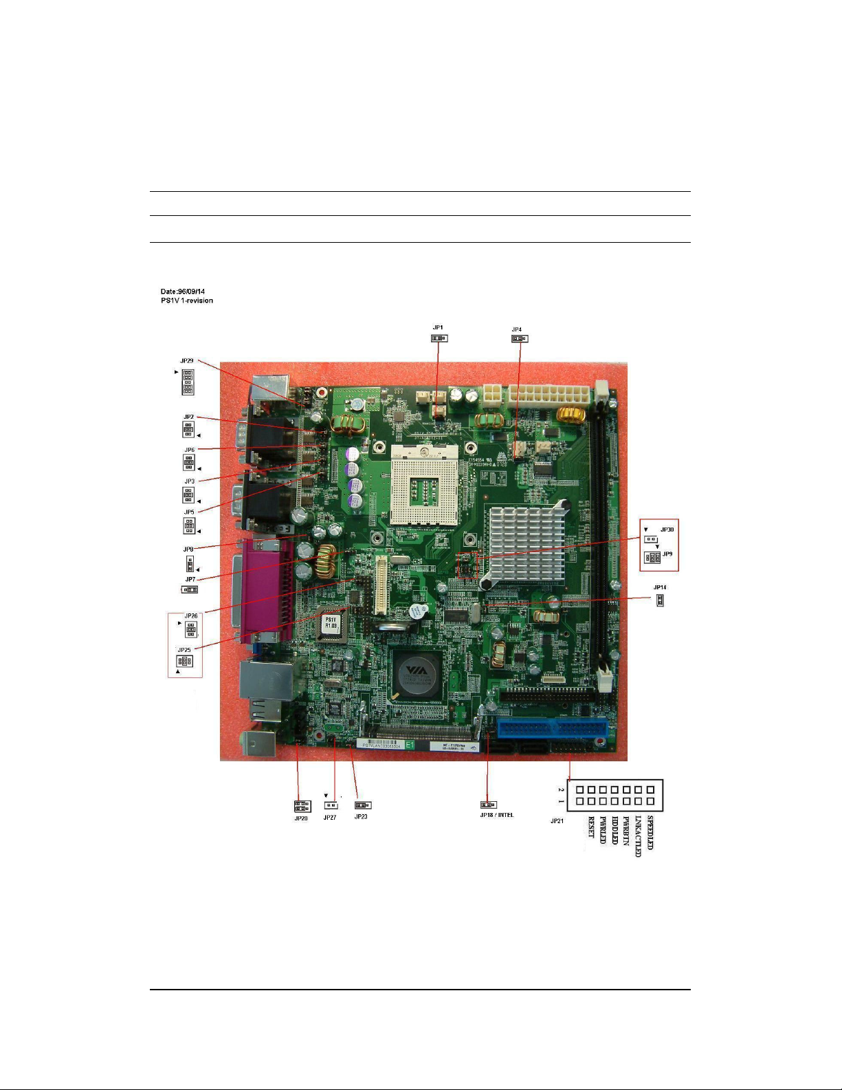
JUMPERS LOCATIONS ON THE PS1V
Page 11
11
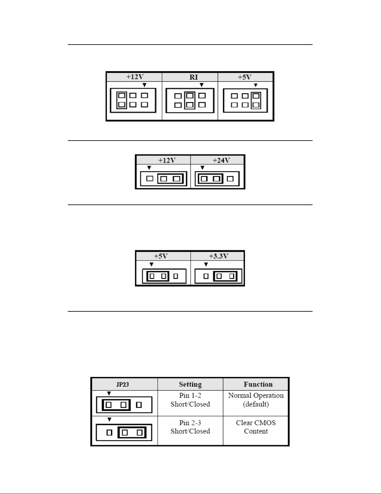
JP2, JP3, JP5, JP6, JP25 ,JP26: COM Power Selection
JP1, JP3, JP5, JP6, JP25, JP26 can be used to selection the COM supply
power: +5V, Ring-IN or +12V.
.
JP8: RJ12 Output Voltage Selection
JP7: LCD PANEL Power Selection
JP7 can be used to selection the LCD supply power :+3.3V or +5V. The default
setting is on +3.3V. User must check the LCD specs and adjust this jumper to
make panel work well in specified power rail.
JP23: Clear CMOS RAM Data
This 3-pin Jumper allows user to disconnect the built-in 3V battery power to
clear the information stored in the CMOS RAM. To clear the CMOS data: (1)
Turn off the system power, (2) Remove jumper cap from pin1 and 2, (3)Short
the pin2 and pin3 for three seconds, (4) Put jumper cap back to pin1 and 2.
(5)Turn on your computer, (6) Hold Down<Delete> during boot up and enter
BIOS setup to enter your preferences.
Page 12
12
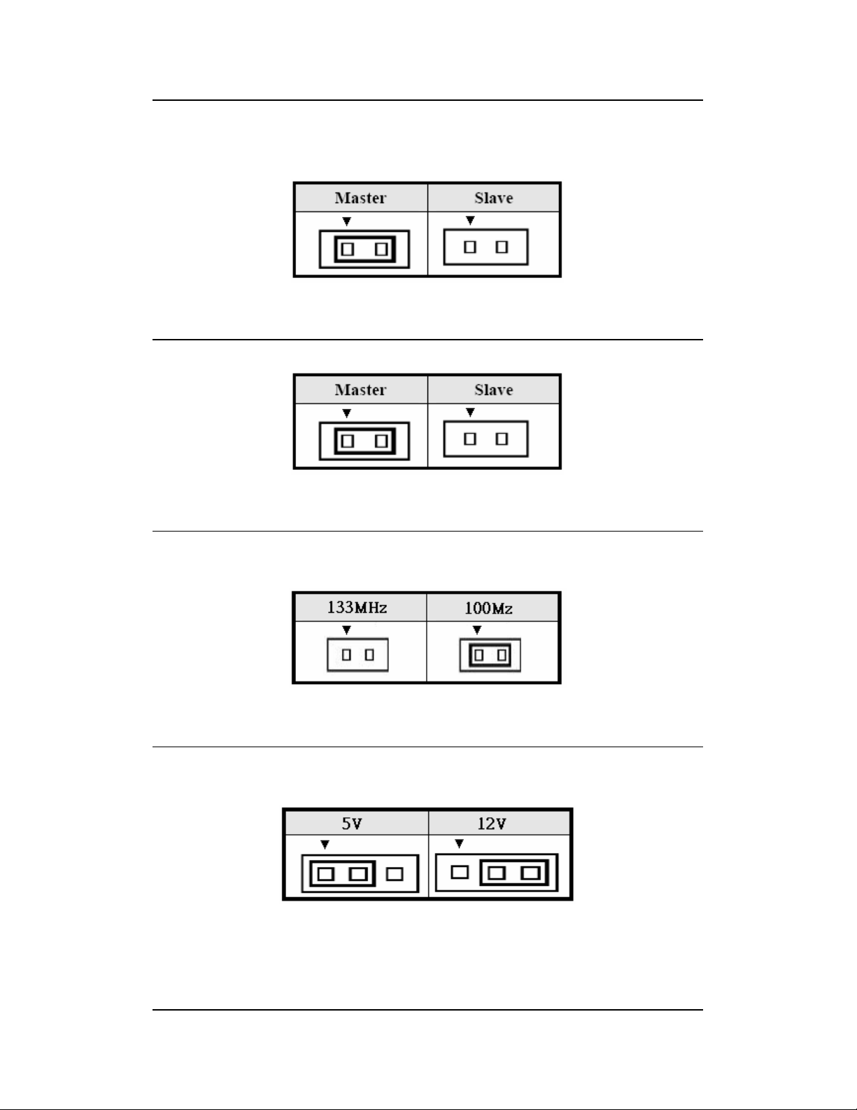
JP16: CF Card Mode Selection
This jumper is set to CF card works on secondary channel and only master
device. Let this pin short if CF card is setting.
JP17: IDE Mode Selection
JP14: Front Side Bus Selection
JP14 can be used to select the front side bus frequency.
JP1: FAN Power Rail Selection
JP1 can be used to select fan’s power rail.
Page 13
13
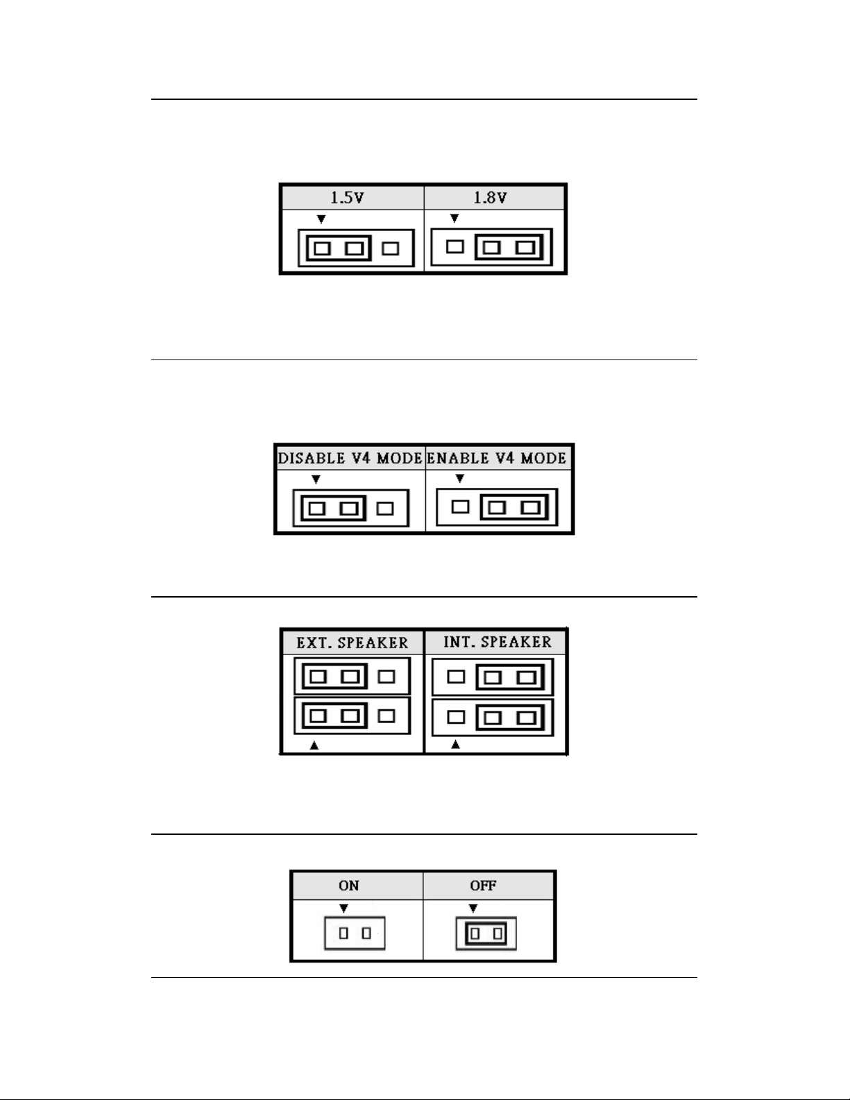
JP4: CPU PLL Supply Voltage Selection
JP4 can be used to select CPU’s PLL
Pentium-M(Dothan), Celeron-M(Dothan), C7-M are 1.5V.
JP18 V4 Mode Selection
To enable V4 mode for VIA CPU.
To disable V4 mode for INTEL CPU.
JP20: Audio Output Selection
JP27: Mini PCI ON/OFF Selection
Page 14
14
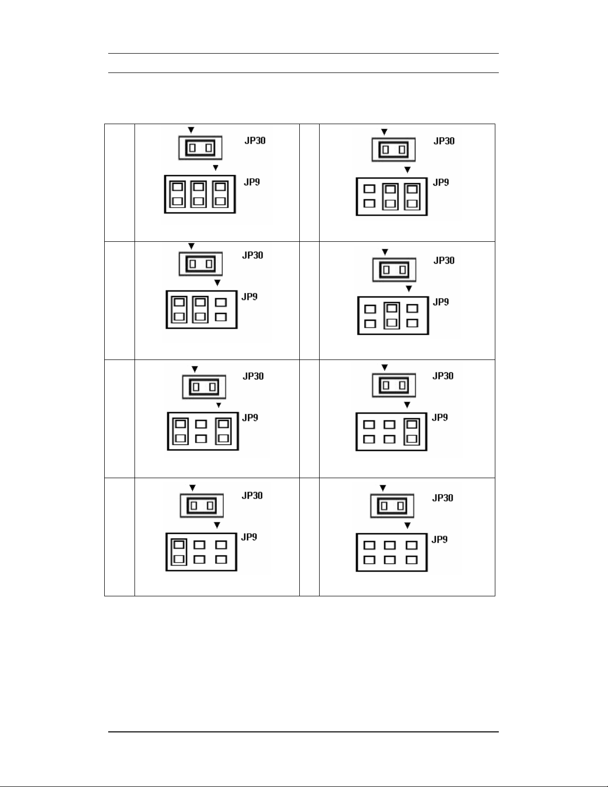
JP9 / JP30 : LVDS Resolution Selection
0
1
2
1024x768x24 (Single)
800x600x18 (Single)
4
1280x1024x24 (Dual)
5
1400x1050x18 (Dual)
6
3
1024x768x18 (Single)
1440x900x18 (Dual)
7
1280x768x18 (Single)
1280x800x18 (Dual)
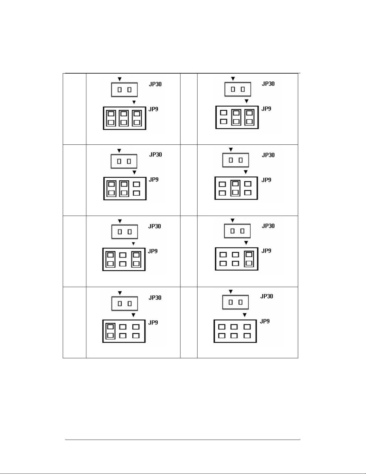
Page 15
15
8
9
10
1600x1200x18 (Single)
1366x768x18 (Single)
12
640x480x18 (Single)
13
1024x768x24 (Dual)
14
11
640x480x18 (Single)
1280x768x24 (Single)
15
1024x768x18 (Dual)
Reverse
Page 16
16
JP29:PS2 Device Function Selection
JP29 can be selected as build-in PS2 keyboard and mouse connector or wired
to external device.
Page 17

17
Connectors on the PS1V
The connectors on the PS1V allows you to connect external devices such as
keyboard, floppy disk drive, hard disk drive, printers, etc. The following table
lists the connectors on the PS1V and their respective page number.
Con n e ct o r Loc a t io n s on the P S1 V … …… … … …… … … ……… … …. . … …… 1 8
F r on t P an el C on n ec t or … …… … …… … ……… …… ……… …… …… …… …. 1 9
B a ck li gh t C onn ec t or … …… … …… … …… … ……… …… …… …… …… … …. . 20
R J 1 2 C on ne c to r …… …… …… … …… …… … …… …… …… … …… …… … … . 21
E I DE C on n ec to r… …… … …… … …… … …… … …… … …… … …… …… …… . .2 2
CO M 1, C OM 2 S er ia l Po rt s… …… …… … …… …… .. …… …… …… …… … .…2 4
C O M3 ~CO M6 Se r ia l Po rt s…… … ……… … …… ….. … ……… …… …… ….… 2 4
L P T P or t… …… …… … …… …… … …… …… … …. .… … …… …… … …… …… . 25
PS/2 keyboa r d & Mo u s e Co nne c tor … … … … ….. … … ……………… … … ….. 2 6
V G A C o nn ect or … …… … …… … …… …… …… … …… …… …… … …… …… … 26
CPU / Sys t e m Fa n P ow e r Co n nec t o r… …… … … …………… … … … ……… 27
DR V PW R1 , DR V PW R2 Co n nec t ors … …… …… …… …… …… …… …… …… 27
L A N- RJ 45 + USB 1/ 2 C on nec to r…… … ……… … …… …… … …… …… ……… . 27
U S B3 / 4 C on n ec t or … ……… …… ……… ……… …… ……… …… …… … .… … .27
US B 5/6 & 7 /8 Conn e ct or … …… … …… … …… … … …… … …… … …… . …… .28
ATX 4P Po w e r Co n ne c tor… … …… . …… …… … …… … …… … …… … …… .… 2 8
Au dio C o nn ec t or … … …… … ……… … …… … ……… …… …… …… … ……. ….2 8
ATX 20P Po we r Conn e c to r ……… … .… … … … …… … …… … … …… … … …… 2 9
C D _IN C on nec to r…… … ……… …… …… ……… … ……… …… ……… … .. .. … 29
LV D S LC D Co n ne c to r… …… …… … …… …… … …… …… … …… …… … …… .. 3 0
D I O C o nn e ct or …… … …… … …… ……… …… …… … …… … …… …… …… . …3 1
Au d io In t. Con n ec to r… …… …… …… …… … …… …… …… … …… …… …… …3 1
Page 18
18
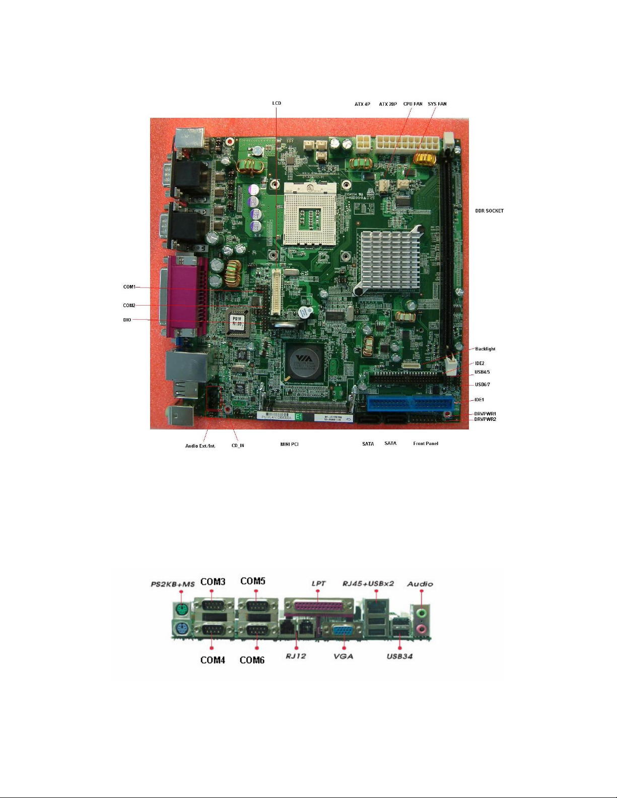
Connector Locations on the PS1V
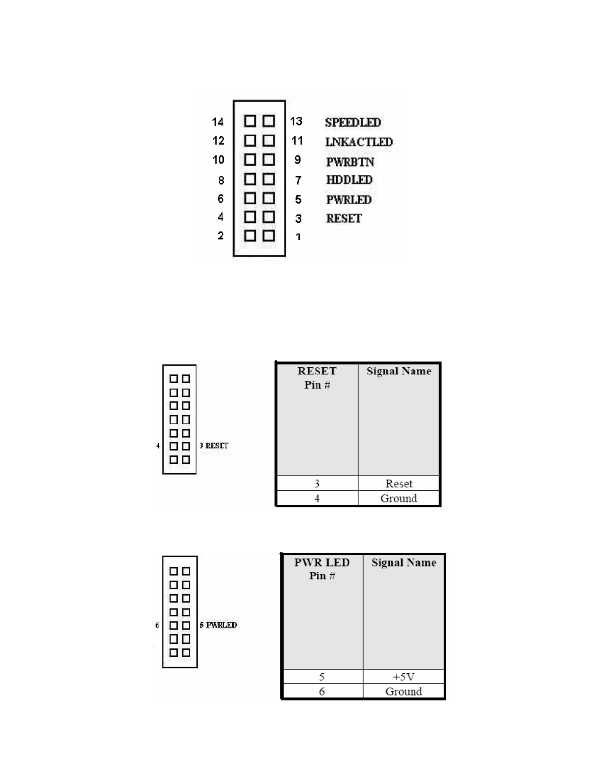
Front Panel Connector
Page 19
19
The front panel of the case has a control panel, which provides light indication
of the computer activities and switches to change the computer status.
RESET Switch
The reset switch allows the user to force reseting the system.
Orientation is not required when making a connection to this header.
Power-On Led
This connector allows user to connect to Front Panel Power Indicator.
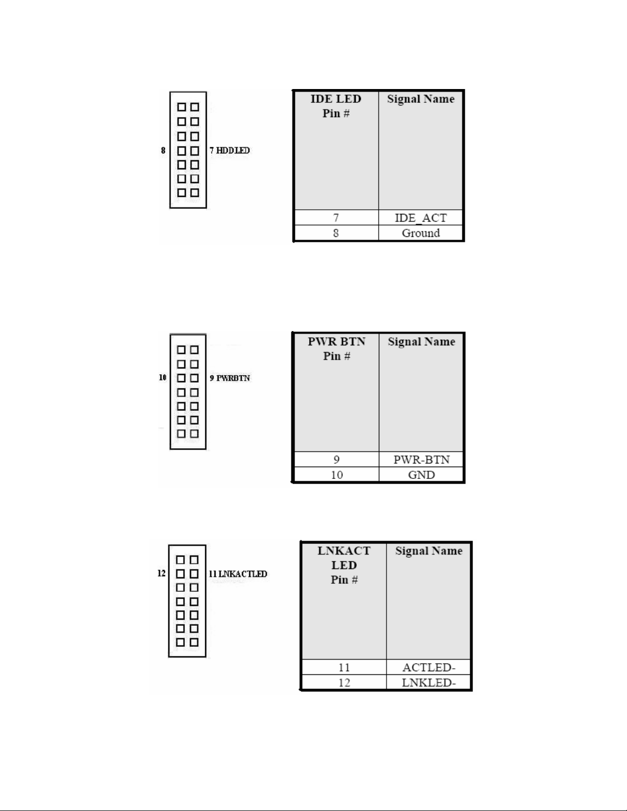
IDE Hard Disk LED Connector
Page 20
20
This Connector connects to the hard drive activity LED on control panel.
This LED will flash when the HDD is being assessed.
ATX Power ON/OFF Button
This 2-pin connector acts as the “Power Supply On/Off Switch” on the SBC
card. When pressed, the switch will force the SBC card to power on. When
pressed again, it will force the SBC card to power off.
LINK_ACT_LED
SPEED_LED
Page 21

21
RJ12 Connector(Cash Drawer)
EIDE Connector
Page 22

22
Page 23

23
Page 24

24
COM1~2 Serial Ports
COM1, COM2, a 10-pin header connector, is the onboard COM1, COM6 serial
port of the PS1V. The following table shows its pin assignments.
COM3~6 Serial Ports
COM3~6, a 9-pin D-sub male connector, is the onboard COM3~6 serial port of
the PS1V. The following table shows its pin assignments.
Page 25

25
LPT Port
The LPT parallel port is a standard D-sub 25-pins female connector.
It can be configured as EPP, ECP or SPP mode.
Page 26

26
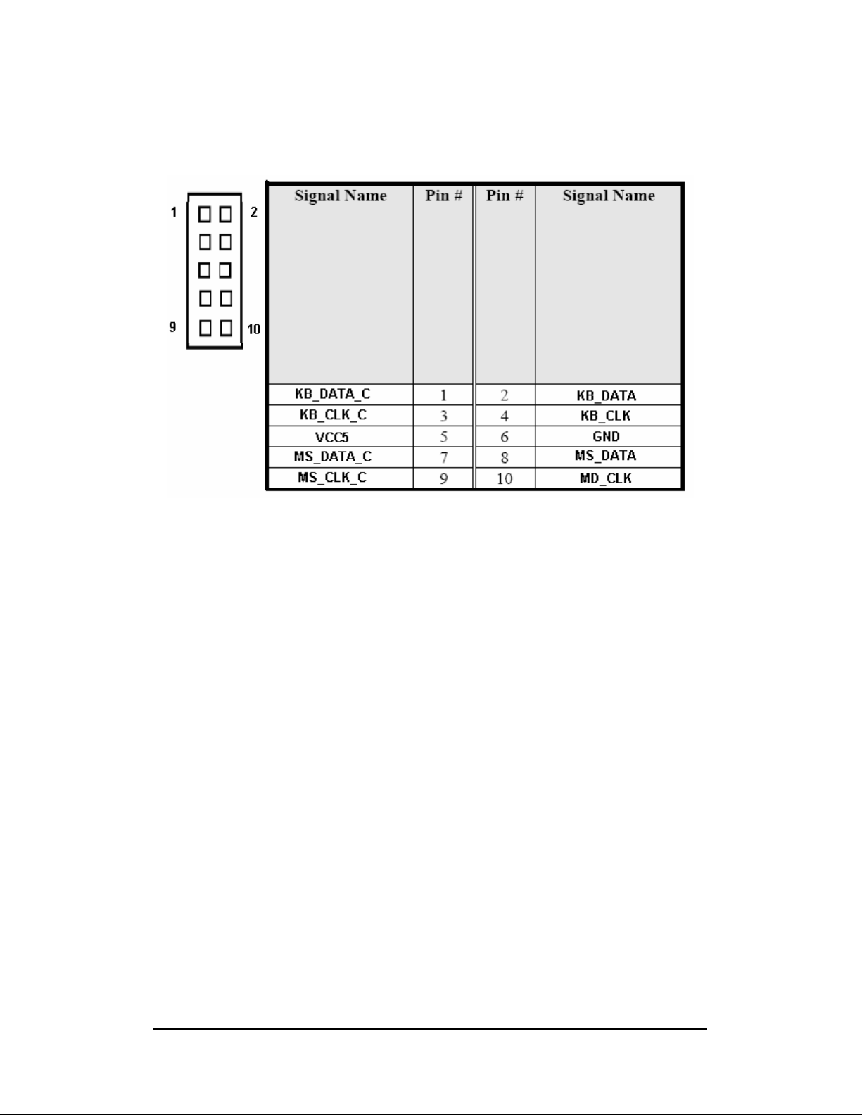
PS/2 Keyboard & Mouse Connector
The following table describes the pin assignment of PS/2 keyboard and mouse
connector.
VGA Connector
The pin assignments of VGA CRT connector are as follows:
Page 27

27
CPU / System Fan Power Connector
This is a 3-pin header for the CPU / System fan. The fan must be a 12V-fan.
DRVPWR1 / DRVPWR2 Connectors.
This is a 2-pin header for the DRVPWR1, 2.
LAN RJ45 USB1/2 Connectors
Below pictures shows the location of LAN RJ45 port and USB ports on the
combo RJ45+USB connector.
USB 3/4 Connectors
The following table shows the pin out of the USB 3/4
Page 28

28
USB 5/6 and USB 7/8 Connectors
The following table shows the pin out of the USB5/6 and USB7/8.
ATX 12V Power Connector
The ATX 12V Power connector mainly supplies power to the CPU
Audio Connector
After install onboard audio driver, you may connector speaker to lineout jack,
microphone to MIC in jack.
Page 29

29
ATX Power Connector
The ATX power connect supplies power to the whole motherboard.
CD_IN Connector
CD_IN connector is designed for wire the CDROM audio signals to the
on-board audio CODEC.
Page 30

30
LVDS LCD Connector
The LCD Panel, inverter for LCD lamp, touch screen serial interface must be
connected to this LVDS header, using the below described connector.
Page 31

31
DIO Connector
DIO port support 8 digital I/O bits. Each bit can be configured as input or output
individually. All bits are 5V tolerance.
AUDIO INT Connector
Page 32

32
Chapter 3 BIOS Setup
This chapter describes the different settings available in the AMI BIOS that
comes with the M/B. The topics covered in the this chapter are as follows :
BIOS Introduction...............................................................................................................33
BIOS Setup Menu ..............................................................................................................35
Standard BIOS Features....................................................................................................37
Advanced BIOS Features ..................................................................................................38
Advanced Chipset Features...............................................................................................50
PCI/PnP Resource Management .......................................................................................55
Boot Configuration Features ..............................................................................................56
Power Management Features............................................................................................57
BIOS Security Features .....................................................................................................58
Load Optimal Defaults .......................................................................................................61
Load Failsafe Defaults .......................................................................................................61
Discard Changs ................................................................................................................. 61
Save Changes and Exit ..................................................................................................... 62
Discard Changes and Exit ................................................................................................ 62
Page 33

33
BIOS Introduction
This Chapter discusses AMI Setup program built into the M/B BIOS . The
Setup program allows users to modify the basic system configuration .
The AMI BIOS installed in the M/B is a custom version of an industry standard
BIOS . This means
That it supports Intel Dothan series CPU & VIA C7-M(V4 BUS) CPU . The
BIOS provides critical low-level support for standard devices such as disk
drives and serial and parallel ports .
It also adds non-standard, features such as virus and password protection as
well as special support for detailed fine-tuning of the chipset controlling the
entire system.
The rest of this chapter is intended to guide you through the process of
configuring your system using Setup.
Starting Setup
The AMI BIOS is immediately activated when you first power on the computer .
The BIOS reads the system information contained in the CMOS and begins the
process of checking out the system and configuring it. When it finishes, the
BIOS will seek an operating system on one of the disks and then launch and
turn control over to the operating system.
While the BIOS in control, the Setup program can be activated in the way:
Press DEL to enter SETUP
If the message disappears before you respond and you still wish to enter
Setup, restart the system to try again by turning it OFF then ON or pressing the
“RESET” button on the system case, You may also restart by simultaneously
pressing <Ctrl>,<Alt>,and<Delete>Keys.
Using Setup
In general, you use the arrow keys to highlight items, press <Enter> to select ,
press <F1> for Help and press <ESC> to quit. The following table provides
more detail about how to navigate In the Setup program using the keyboard.
Page 34

34
Key Function
↑↓← → Arrow
Esc
+ / - Increase / decrease the value
F1 Key General Help
F7 Key Discard change
F8 Key Load Fail-Safe Defaults
F9 Key Load Optimized Defaults
F10 Key Save configuration changes and exit setup
Move to the item
Main menu: Discard changes and exit setup
Submenus: Exit Current page to the next higher level
menu
Page 35

35
BIOS Setup Menu
The setup uses a menu interface to allow the user to configure their system.
The features are
Standard BIOS Features:
Allows the user to specify system time and system date and the system
overview.
Advanced BIOS Features:
Allows the user to set BIOS function .
Advanced Chipset Features:
Allows the user to set Chipset function .
PCI/PNP Resource Management:
Allows the user to set Onboard IO function
Boot Configuration Features:
Allow the user to set the boot sequence
Page 36

36
Power Management Features:
Allow the user to set the APM / ACPI function
BIOS Security Features:
Allows the user to set the password for system.
Load Optimal Defaults:
Load Optimal Default values for all the setup questions.
Load Failsafe Defaults:
Load Failsafe Default values for all the setup questions.
Discard Changes:
Discards changes done so far to any of the setup questions.
Save Changes and Exit:
Exit system setup with saving the changes.
Discard Changes and Exit:
Exit system setup without saving the changes.
Page 37

37
Standard BIOS Features
System Overview
AMI BIOS
Display BIOS version and build date
Processor
Display CPU Type and Speed
System Memory
Display System memory , and it does not include share VRAM .
System Time (hh/mm/ss) & System Date ( week mm/dd/yyyy) :
Allows the user to set the time and date.
The Time is displayed in 24 hours format.
The Date can be set from January 1st, 1980 to December 31, 2099
The values set in these two fields take effect immediately.
Page 38

38
Advanced BIOS Features
CPU Configuration:
Allow the user to set CPU function.
IDE Configuration:
Allow the user to set IDE function.
SuperIO Configuration:
Allow the user to set SuperIO function.
USB Configuration:
Allow the user to set USB function.
Hardware Health Configure:
Use the menu to display the CPU / System temperature, FAN speed and
voltages
Page 39

39
Configure advanced CPU settings
Intel® SpeedStep™ tech:
Allows the user to select CPU Intel® SpeedStep™ tech function .
( Celeron-M dose not support )
[Maximum Speed] : Set CPU speed to maximum. (Default)
[Minimum Speed] : Set CPU speed to minimum.
[Automatic] : Set CPU speed controlled by operating system .
[Disabled] : Set CPU speed to default .
Page 40

40
IDE Configuration
Primary IDE Master
Allow the user to set primary IDE master device function
40 / 80 Pin
Primary IDE Slave
Allow the user to set primary IDE slave device function
40 / 80 Pin
Secondary IDE Master
Allow the user to set secondary IDE master device function
44 Pin IDE & CF Card IDE interface ( Default )
Secondary IDE Slave
Allow the user to set secondary IDE slave device function
44 Pin IDE ( Default ) & CF Card IDE interface
Third SATA Master
Allow the user to set Third SATA master device function
Page 41

41
Fourth SATA Master
Allow the user to set Fourth SATA master device function
OnBoard SATA-IDE
Allow the user to set Onboard SATA-IDE setting
[Disabled] : Disabled OnBoard SATA-IDE device .
[SATA] : Enabled OnBoard SATA-IDE device .
[RAID] : Enabled OnBoard SATA-IDE device and support RAID function
Page 42

42
Primary IDE Master / Primary IDE Slave / Secondary IDE Master /
Secondary IDE Slave Device settings
Primary IDE Master Information:
Display IDE device Type / Vendor / Size / function mode / S.M.A.R.T supported
Type
Allow the user to set IDE device type
[ Not Installed ] : Disable the IDE device
[ Auto ] : Set the IDE controlled by operating system
[ CD/DVD ] : Set the IDE device type to CD/DVD
LBA/Large Mode
Allow the user to set IDE device access mode
[ Disable ] : Disable the IDE LBA access mode
[ Auto ] : Enable the IDE LBA mode
Block (Multi-Sector Transfer)
Allow the user to set IDE device support Block mode
Page 43

43
[ Auto ] : The Data transfer from and to the device occurs multiple sectors at a
time if the device supports it .
[ Disabled ] : The Data transfer from and to the device occurs one sector at a
time .
PIO Mode
Allow the user to set IDE device support PIO mode
[ Auto / 0 / 1 / 2 / 3 / 4 ] : Set the PIO mode to Auto / PIO 0 / PIO 1 / PIO 2 / PIO
3 / PIO 4
DMA Mode
Allow the user to set IDE device support DMA mode
[ Auto / SWDMA0 / SWDMA1 / SWDMA2 / MWDMA0 / MWDMA1 / MWDMA2 /
UDMA0 / UDMA1 / UDMA2 / UDMA3 / UDMA4 / UDMA5 ] : Select DMA mode
AUTO : Auto detected
SWDMAn : SingleWordDMAn
MWDMAn: MultiWordDMAn
UDMAn : UltraDMAn
S.M.A.R.T.
S.M.A.R.T. stands for Self-Monitoring, Analysis and Reporting Technology
Supported .
[ Auto ] : Set S.M.A.R.T. controlled by operating system
[ Disable ] : Set S.M.A.R.T. function to disable
[ Enable ] : Set S.M.A.R.T. function to enable
32Bit Data Transfer
Allow the user to set IDE device support 32Bit Data transfer
[ Disabled ] : Disabled 32Bit Data transfer function
[ Enabled ] : Enabled 32Bit Data transfer function
Page 44

44
SuperIO Configuration
Configure Super IO Chipset :
Allow the user to set COM1 / COM2 / COM3 / COM4 / COM5 / COM6 / LPT
port IO address & IRQ settings
OnBoard Serial Port1 Address
Allow the user to select Serial Port1 Base Addresses / IRQ Settings
[ Disable ] : Disable Serial Port1
[ 3F8 / IRQ4 ] : Set base address 3F8 and interrupt IRQ4 to COM1 Port
( Default )
[ 3E8 / IRQ4 ] : Set base address 3E8 and interrupt IRQ4 to COM1 Port
[ 2E8 / IRQ3 ] : Set base address 2E8 and interrupt IRQ3 to COM1 Port
OnBoard Serial Port2 Address
Allow the user to select Serial Port2 Base Addresses / IRQ Settings
[ Disable ] : Disable Serial Port2
[ 2F8 / IRQ3 ] : Set base address 2F8 and interrupt IRQ3 to COM2 Port
( Default )
Page 45

45
[ 3E8 / IRQ4 ] : Set base address 3E8 and interrupt IRQ4 to COM2 Port
[ 2E8 / IRQ3 ] : Set base address 2E8 and interrupt IRQ3 to COM2 Port
External Serial Port3 Address
Allow the user to select Serial Port3 Base Addresses
[ Disable ] : Disable Serial Port3
[ 3F8 ] : Set base address 3F8 to COM3 Port
[ 2F8 ] : Set base address 2F8 to COM3 Port
[ 3E8 ] : Set base address 3E8 to COM3 Port ( Default )
[ 2E8 ] : Set base address 2E8 to COM3 Port
[ 2F0 ] : Set base address 2F0 to COM3 Port
[ 2E0 ] : Set base address 2E0 to COM3 Port
Serial Port3 IRQ
Allow the user to select Serial Port3 IRQ
[4] : Set interrupt mode to IRQ4
[9] : Set interrupt mode to IRQ9
[10] : Set interrupt mode to IRQ10
[11] : Set interrupt mode to IRQ11( Default )
External Serial Port4 Address
Allow the user to select Serial Port4 Base Addresses
[ Disable ] : Disable Serial Port4
[ 3F8 ] : Set base address 3F8 to COM4 Port
[ 2F8 ] : Set base address 2F8 to COM4 Port
[ 3E8 ] : Set base address 3E8 to COM4 Port
[ 2E8 ] : Set base address 2E8 to COM4 Port ( Default )
[ 2F0 ] : Set base address 2F0 to COM4 Port
[ 2E0 ] : Set base address 2E0 to COM4 Port
Serial Port4 IRQ
Allow the user to select Serial Port4 IRQ
[3] : Set interrupt mode to IRQ3
[9] : Set interrupt mode to IRQ9
[10] : Set interrupt mode to IRQ10( Default )
[11] : Set interrupt mode to IRQ11
Page 46

46
External Serial Port5 Address
Allow the user to select Serial Port5 Base Addresses
[ Disable ] : Disable Serial Port5
[ 3E8 ] : Set base address 3F8 to COM5 Port
[ 2E8 ] : Set base address 2F8 to COM5 Port
[ 2F0 ] : Set base address 3E8 to COM5 Port( Default )
[ 2E0 ] : Set base address 2E8 to COM5 Port
[ 2D8 ] : Set base address 2F0 to COM5 Port
[ 2D0 ] : Set base address 2E0 to COM5 Port
Serial Port5 IRQ
Allow the user to select Serial Port5 IRQ
[4] : Set interrupt mode to IRQ4
[5] : Set interrupt mode to IRQ5
[6] : Set interrupt mode to IRQ6
[7] : Set interrupt mode to IRQ7
[9] : Set interrupt mode to IRQ9
[10] : Set interrupt mode to IRQ10
[11] : Set interrupt mode to IRQ11( Default )
[12] : Set interrupt mode to IRQ12
External Serial Port6 Address
Allow the user to select Serial Port6 Base Addresses
[ Disable ] : Disable Serial Port6
[ 3E8 ] : Set base address 3F8 to COM6 Port
[ 2E8 ] : Set base address 2F8 to COM6 Port
[ 2F0 ] : Set base address 3E8 to COM6 Port
[ 2E0 ] : Set base address 2E8 to COM6 Port ( Default )
[ 2D8 ] : Set base address 2F0 to COM6 Port
[ 2D0 ] : Set base address 2E0 to COM6 Port
Serial Port6 IRQ
Allow the user to select Serial Port6 IRQ
[3] : Set interrupt mode to IRQ3
[5] : Set interrupt mode to IRQ5
Page 47

47
[6] : Set interrupt mode to IRQ6
[7] : Set interrupt mode to IRQ7
[9] : Set interrupt mode to IRQ9
[10] : Set interrupt mode to IRQ10( Default )
[11] : Set interrupt mode to IRQ11
[12] : Set interrupt mode to IRQ12
Parallel Port Address:
Allow the user to select Parallel Port Base address
[ Disable ] : Disable Parallel Port
[ 378 ] : Set base address 378 to Parallel Port( Default )
[ 278 ] : Set base address 278 to Parallel Port
[ 3BC ] : Set base address 3BC to Parallel Port
Parallel Port Mode:
Allow the user to select Parallel Port Mode
[ Normal ] : Set Parallel Port Mode to Normal mode. ( Default )
[ Bi-Directional ] Set Parallel Port Mode to Bi-Directional mode
[ EPP ] : Set Parallel Port Mode to EPP mode.
[ ECP & EPP ] : Set Parallel Port Mode to ECP & EPP mode.
Parallel Port IRQ:
Allow the user to select Parallel Port IRQ.
[ IRQ5] : Set interrupt mode to IRQ5
[ IRQ7] : Set interrupt mode to IRQ7 ( Default )
Page 48

48
USB Configuration
Legacy USB Support
Allow the user to set legacy USB supported
[ Disabled ] : Set legacy USB device supported disabled
[ Enabled ] : Set legacy USB device supported enabled( Default )
[ Auto ] : Set legacy USB device controlled by operating system , AUTO option
disables legacy support if no USB device are connected .
USB Keyboard Legacy Support
Allow the user to set legacy USB keyboard supported
[ Disabled ] : Set legacy USB keyboard supported disabled
[ Enabled ] : Set legacy USB keyboard supported enabled( Default )
USB Mouse Legacy Support
[ Disabled ] : Set legacy USB mouse supported disabled
[ Enabled ] : Set legacy USB mouse supported enabled( Default )
Page 49

49
Hardware Health Configuration
Current CPU DIE Temperature
Show CPU Temperature .
Current SYSTEM Temperature
Show SYSTEM Temperature .
Current CPU FAN Speed
Show CPU FAN Speed .
Current SYSTEM FAN Speed
Show SYSTEM FAN Speed .
Vcore / 1.05V / 2.5V / 3.3V / 5V / 12V Voltages
Show Power rails voltage
Page 50

50
Advanced Chipset Features
DRAM Frequency
Allow the user to set DRAM frequency function
[ Auto ] : Set DRAM Frequency controlled by operating system( Default )
[ 400 MHz ] : Set DRAM Frequency to 400 MHz
[ 533 MHz ] : Set DRAM Frequency to 533 MHz
DRAM Timing
Allow the user to set DRAM timing function
[ Manual ] : Set DRAM Timing to Manual mode
[ Auto ] : Set DRAM Timing controlled by operating system( Default )
[ Turbo ] : Set DRAM Timing to Turbo mode
[ Ultra ] : Set DRAM Timing to Ultra mode
VGA Frame Buffer Size
Allow the user to set VRAM Size
[ 8M ] : Set VGA Frame Buffer Size to 8 MB
[ 16M ] : Set VGA Frame Buffer Size to 16 MB
[ 32M ] : Set VGA Frame Buffer Size to 32 MB
[ 64M ] : Set VGA Frame Buffer Size to 64 MB( Default )
Select Display Device
Allow the user to set boot display device
Page 51

51
[ CRT ] : Set boot display to CRT only
[ LCD ] : Set boot display to LCD only
[ CRT+LCD ] : Set boot display to CRT + LCD both( Default )
Panel Switch
Allow the user to set Panel Type from Hardware Jumper or Software CMOS
Settings .
[ Hardware Strapping ] : Set Panel Type from Hardware Jumper (JP9 , JP30).
Page 52

52
0
4
1
2
3
1024x768x24 (Single)
800x600x18 (Single)
1024x768x18 (Single)
1280x1024x24 (Dual)
5
1400x1050x18 (Dual)
6
1440x900x18 (Dual)
7
8
1280x768x18 (Single)
1280x800x18 (Dual)
12
1600x1200x18 (Single)
640x480x18 (Single)
Page 53

53
9
13
10
1366x768x18 (Single)
14
1024x768x24 (Dual)
11
640x480x18 (Single)
15
1280x768x24 (Single)
1024x768x18 (Dual)
Reverse
[ Software Setting ] : Set Panel Type from Software CMOS settings .
Panel ID Resolution Channel Dithering
0 640x480 1 Enable
1 800x600 1 Enable
2 1024x768 1 Enable
3 1280x768 1 Enable
4 1280x1024 2 Disable
5 1400x1050 2 Enable
6 1440x900 2 Enable
7 1280x800 2 Enable
8 1600x1200 1 Enable
9 1366x768 1 Enable
10(A) 640x480 1 Enable
11(B) 1024x768 2 Enable
12(C) 1024x768 1 Disable
13(D) 1024x768 2 Disable
14(E) 1280x768 1 Disable
Page 54

54
Dithering Enable is for 18 bits panel and Disable is for 24 bits panel.
Channel 1 is for Single Channel and Channel 2 is for Daul Channel .
Brightness Inverse
Allow the user to inverse brightness up / down .
[ Disabled ] : Set Brightness to normal mode . That Brightness up / down
function will work normal .
[ Enabled ] : Set Brightness to inverse mode . That Brightness up / down
function will work inverse . The function is support some Panel will make
brightness down after press brightness up button .
V-LINK mode selection
Allow the user to set V-Link mode function
[ Auto ] : Set V-LINK mode controlled by operating system ( Default )
[ Mode 0 ] : Set V-LINK mode to Mode 0
[ Mode 1 ] : Set V-LINK mode to Mode 1
OnBoard AC’97 Audio
Allow the user to set AC’97 Audio device function
[ Enabled ] : Set AC’97 Audio device to Enabled ( Default )
[ Disabled ] : Set AC’97 Audio device to Disabled
Page 55

55
PCI / PNP Resource Management
PCI IDE BusMaster
Allow the user to set PCI IDE BusMaster supported
[ Disabled ] : Set PCI IDE BusMaster to disabled.
[ Enabled ] : Set PCI IDE BusMaster to enabled . ( Default )
IRQ Resources Setting
Allow the user to set PCI/ISA PnP device resources
IRQ3 / IRQ4 / IRQ5 / IRQ7 / IRQ9 / IRQ10 / IRQ11 / IRQ14 / IRQ15
[ Available ] : Specified IRQ is available to used by PCI/PnP devices.
[ Reserved ] : Specified IRQ is reserved for use by Legacy ISA devices .
Page 56

56
Boot Configuration Features
Quick Boot
Allow the user to skip certain tests while booting . This will decrease the time
needed to boot the system
[ Enabled ] : Set Quick boot enabled. ( Default )
[ Disabled ] : Set Quick boot disabled .
Bootup Num-Lock
Allow the user to select Power-On state for Num lock
[ Off ] : Set Bootup Num-Lock to OFF( Default )
[ On ] : Set Bootup Num-Lock to On
1st / 2nd / 3rd / 4th / 5th Boot Device
Allow the user to select boot device.
Default boot device priority list :
[IDE-HDD] – [SATA-HDD] – [CD/DVD] – [Removable Disk] – [Network] –
[Disabled]
Display Logo
Allow the OEM to Display or Disable OEM LOGO
[ Disabled ] : Displays normal POST messages. ( Default )
[ Enabled ] : Displays OEM Logo instead of POST messages.
Page 57

57
Power Management Features
ACPI Version Features
Allow the user to select ACPI 2.0 version supported
[ ACPI v1.0] : Support ACPI 1.0
[ ACPI v2.0] : Support ACPI 2.0
[ ACPI v3.0] : Support ACPI 3.0 ( Default )
ACPI APIC support
Allow the user to select ACPI APIC supported . Include ACPI APIC table
pointer to RSDT pointer list .
[ Disabled ] : Disabled ACPI APIC supported
[ Enabled ] : Enabled ACPI APIC supported ( Default )
USB Device Wakeup Function
Allow the user to select USB device wakeup function supported
[ Disbaled ] : Disabled USB device wakeup function
[ Enabled ] : Enabled USB device wakeup function ( Default )
Page 58

58
BIOS Security Features
Supervisor Password
Indicates whether a supervisor password has been set. If the password has
been installed, Installed displays. If not, Not Installed displays.
Allow the user to key in 6 digital value.
After key in new password , you need to confirm new password.
Page 59

59
After confirm new password, the password installed success .
Change Supervisor Password
Select this option and press <Enter> to access the sub menu. You can use the
sub menu to change the supervisor password.
Not allow the user to key in space value.
Select Change Supervisor Password from the Security Setup menu and press
<Enter>.
Enter New Password, if user to key in space value an error message appears
as
“Password uninstalled” ,Not allow the user to key in space value .
Change User Password::::
User Password
Indicates whether a user password has been set. If the password has been
installed, Installed displays. If not, Not Installed displays.
Change User Password
Select this option and press <Enter> to access the sub menu. You can use the
sub menu to change the user password.
Page 60

60
Change User Password
Select Change User Password from the Security Setup menu and press
<Enter>. Enter New Password: appears. Type the password and press
<Enter>. The screen does not display the characters entered. Retype the
password as prompted and press <Enter>. If the password confirmation is
incorrect, an error message appears.
Password check::::
Setup: Check password while invoking setup.
Always : Check password while invoking setup a well as on each boot.
Default is “Setup”.
Page 61

61
Load Optimal Defaults
Load Optimal Default values for all the setup questions .
If select [OK] , Load Optimal Default values for all the setup questions.
If select [Cancel] , Exit the prompt massage.
Load Failsafe Defaults
Load Failsafe Default values for all the setup questions .
If select [OK] , Load Failsafe Default values for all the setup questions.
If select [Cancel] , Exit the prompt massage.
Discard Changes
If select [OK] , Discards changes done so far to any of the setup questions.
If select [Cancel] , Exit the prompt massage.
Page 62

62
Save Changes and Exit :
If select [OK] , Exit system setup after saving the changes.
If select [Cancel] , Exit the prompt massage.
Discard changes and Exit:
If select [OK] , Exit system setup without saving any changes.
If select [Cancel] , Exit the prompt massage.
Page 63

63
Chapter 4 Appendix
I/O Port Address Map ........................................................................................................ 62
Interrupt Request Lines(IRQ).............................................................................................63
POST Beep........................................................................................................................64
Page 64

64
A. I/O Port Address Map
Each peripheral device in the system is assigned a set of I/O port address which also
becomes the identity of the device. There are a total 1K port address space available.
The following table lists the I/O port addresses used on the Industrial CPU Card .
Address Device Description
000h-00Fh DMA Controller
020h-021h INT Controller
040h-043h System Timer
060h-060h Keyboard Controller
061h-061h System Speaker
064h-064h Keyboard Controller
070h-071h System CMOS / Real time clock
081h-083h DMA Controller
087h-087h DMA Controller
089h-08Bh DMA Controller
08Fh-08Fh DMA Controller
0A0h-0A1h INT Controller
0F0h-0FFh Numeric data processor
170h-177h Secondary IDE Channel
1F0h-1F7h Primary IDE Channel
274h-277h ISAPNP Read data Port
279h-279h ISAPNP Read data Port
2E0h-2E7h Serial Port#6 (COM6)
2E8h-2EFh Serial Port#4 (COM4)
2F0h-2F7h Serial Port#5 (COM5)
2F8h-2FFh Serial Port#2 (COM2)
376h-376h Secondary IDE Channel
378h-37Fh Printer Port#1 (LPT1)
3B0h-3DFh VGA Controller
3E8h-3EFh Serial Port#3 (COM3)
3F6h-3F6h Primary IDE Channel
3F8h-3FFh Serial Port#1 (COM1)
Page 65

65
B. Interrupt Request Lines ( IRQ )
There are a total of 15 IRQ lines available on the Industrial CPU Card. Peripheral
devices use interrupt request lines to notify CPU for the service required. The
following table shows the IRQ used by the devices on the Industrial CPU Card.
Level Function
IRQ0 System Timer
IRQ1 Keyboard
IRQ3 Serial Port#2
IRQ4 Serial Port#1
IRQ5 Reserved
IRQ6 Reserved
IRQ7 Parallel Port#1
IRQ8 Real Time Clock
IRQ9 ACPI
IRQ10 Serial Port#4 & Serial Port#6
IRQ11 Serial Port#3 & Serial Port#5
IRQ12 PS/2 Mouse
IRQ13 Reserved
IRQ14 Primary IDE
IRQ15 Secondary IDE
Page 66

66
C. POST Beep
Boot Block Beep Codes
Number of Beeps
1
2
3
4
5
6
7
8
9
10
11
12
13
Insert diskette in floppy drive A:
‘AMIBOOT.ROM’ file not found in root directory of diskette in A:
Base Memory error
Flash Programming successful
Floppy read error
Keyboard controller BAT command failed
No Flash EPROM detected
Floppy controller failure
Boot Block BIOS checksum error
Flash Erase error
Flash Program error
‘AMIBOOT.ROM’ file size error
BIOS ROM image mismatch (file layout does not match image present in
flash device)
POST BIOS Beep Codes
Description
Number of Beeps
1
2
3
4
5
6
7
8
9
10
11
Description
Memory refresh timer error.
Parity error in base memory (first 64KB block)
Base memory read/write test error
Motherboard timer not operational
Processor error
8042 Gate A20 test error (cannot switch to protected mode)
General exception error (processor exception interrupt error)
Display memory error (system video adapter)
AMIBIOS ROM checksum error
CMOS shutdown register read/write error
Cache memory test failed
 Loading...