

Page 1

PS960GLE/ PS965GME Mainboard
PS960GLE/ PS965GME
Intel® Celeron® processor FSB 533MHz
Intel® Core™ 2 Duo Mobile & Penryn processor FSB 533/800MHz
Intel
Intel® 960GLE + ICH 8M
®
965GME + ICH 8M/ M-E(optional)
MB Dimension
200mm x 195mm
Operating System
Windows® XP/ Linux
Release Date
090914
User's Manual
Ver. 1.0
I
Page 2
PS960GLE/ PS965GME Mainboard
A
Things You Have To Know
0 The images and pictures in this manual are for reference only and may vary from the product
you received depending on specific hardware models, third party components and software
versions.
0 This mainboard contains very delicate IC chips. Always use a grounded wrist strap when
working with the system.
0 Do not touch any IC chip, lead, connector or other components.
0 Always unplug the AC power when you install or remove any device on the mainboard or
when configuring pins and switches.
Symbols
Follow the procedures
ttention- Important
Troubleshooting Tips
Refer to other
II
Page 3

PS960GLE/ PS965GME Mainboard
Index
CHAPTER 1 GETTING STARTED...............................................................................1
1.1 INTRODUCTION ....................................................................................................1
1.2 SPECIFICATION....................................................................................................2
1.2.1 CPU .................................................................................................................................. 2
1.2.2 Chipset.............................................................................................................................. 2
1.2.3 Memory............................................................................................................................. 2
1.2.4 Audio - Realtek® ALC 662................................................................................................. 2
1.2.5 LAN - Realtek® RTL8111C................................................................................................ 3
1.2.6 Slot.................................................................................................................................... 3
1.2.7 Mini-IDE Connector........................................................................................................... 3
1.2.8 I/O Connectors.................................................................................................................. 3
1.2.9 Universal Serial Bus.......................................................................................................... 3
1.2.10 SATA II............................................................................................................................ 3
1.2.11 BIOS ............................................................................................................................... 4
1.2.12 Hardware Monitor............................................................................................................ 4
1.2.13 Power Supply.................................................................................................................. 4
1.3 CONFIGURATION..................................................................................................5
1.3.1 Layout of TOP................................................................................................................... 5
1.4 HARDWARE INSTALLATION ..................................................................................6
Jumpers ..................................................................................................................................... 6
1.4.1 JP1: Clear CMOS Jumper................................................................................................. 6
1.4.2 JP2: CF Card Master/ Slave Jumper................................................................................. 7
1.4.3 JP3: LVDS VDD POWER ................................................................................................. 7
1.4.4 JP4: USB POWER............................................................................................................7
1.4.5 JP5/ JP6: FAN Power .......................................................................................................7
1.4.6 JP7: RJ12 POWER...........................................................................................................8
1.4.7 JP8: MINI PCI ON/OFF..................................................................................................... 8
1.4.8 JP9: EXT. Audio................................................................................................................ 8
1.4.9 CN1 - 6: RS-232 Voltage Setting ...................................................................................... 8
1.4.10 CN12: AUDIO OUTPUT SELECT................................................................................... 9
1.4.11 CN13: KB/MS.................................................................................................................. 9
1.4.12 CN9: LVDS Selection.................................................................................................... 10
1.4.13 CN8 FPSWLED: Front Panel Headers.......................................................................... 11
III
Page 4

PS960GLE/ PS965GME Mainboard
Connectors............................................................................................................................... 12
1.4.14 KBMS1: Mini-DIN PS/2 Port.......................................................................................... 12
1.4.15 CON3/ CON4: COM3/ 4/ 5/ 6 Port ................................................................................ 12
1.4.16 PRT1: LPT PORT ......................................................................................................... 13
1.4.17 RJ12.............................................................................................................................. 13
1.4.18 VGA1: VGA Connector ................................................................................................. 14
1.4.19 LAN1: LAN Port............................................................................................................. 14
1.4.20 USB1: USB Port............................................................................................................ 15
1.4.21 SNDCN2 ....................................................................................................................... 15
1.4.22 COM1/ COM2: COM Port ............................................................................................. 15
1.4.23 CN14: 8-bit GPIO.......................................................................................................... 16
1.4.24 CDIN1 ........................................................................................................................... 16
1.4.25 SPDIF ........................................................................................................................... 16
1.4.26 USB2/ USB3: USB Connector ...................................................................................... 17
1.4.27 SATA1/ SATA2/ SATA3................................................................................................ 17
1.4.28 IDE1: Mini-IDE Connector............................................................................................. 17
1.4.29 CON2: LVDS................................................................................................................. 18
1.4.30 DDRII1/ DDRII2: Memory Installation............................................................................ 19
1.4.31 PWR1: ATX Power Connector...................................................................................... 20
1.4.32 FAN1/ FAN2/ FAN3: FAN Header ................................................................................. 20
1.4.33 MINI_PCI1: Mini PCI Slot .............................................................................................. 21
1.4.34 CON1: CF Card Connector........................................................................................... 21
2.3 MAIN MENU .......................................................................................................22
2.3.1 Standard CMOS Features............................................................................................... 23
2.3.2 Advanced BIOS Features ............................................................................................... 26
2.3.3 Advanced Chipset Features............................................................................................ 31
2.3.4 Integrated Peripherals..................................................................................................... 34
2.3.5 Power Management Setup.............................................................................................. 40
2.3.6 PnP/PCI Configurations .................................................................................................. 44
2.3.7 PC Health Status............................................................................................................. 45
2.3.8 Frequency/Voltage Control ............................................................................................. 46
2.3.9 Load Fail-Safe Defaults...................................................................................................47
2.3.10 Load Optimized Defaults............................................................................................... 48
2.3.11 Set Password................................................................................................................ 49
2.3.12 Save & Exit Setup......................................................................................................... 50
2.3.13 Exit Without Saving ....................................................................................................... 51
IV
Page 5

PS960GLE/ PS965GME Mainboard
Chapter 1 Getting Started
1.1 Introduction
Thanks for choosing PS960GLE/ PS965GME Mainboard. It is based on Intel® 960GLE/ 965GME
Northbridge chipset and Intel
integrated Intel
Celeron
965GME.
The PS960GLE/ PS965GME provide 2 DDR II SO-DIMM sockets which allow you to install 200-pin
DDR II 533(PS960GLE) or 667(PS965GME)MHz SO-DIMM. It supports a total memory capacity of
2(PS960GLE) or 4(PS965GME) GB.
This mainboard provides one MINI-IDE connector for MINI-IDE hard drives, supporting Ultra ATA
100/66/33MHz. and support 3 SATA II (300MB/s). In addition, Mini PCI & CF II slot for use with
standard expansion card is also allowed.
The PS960GLE/ PS965GME provide one VGA (D-Sub) connector, 8 USB 2.0/ 1.1 and 6 RS232 ports
for use. There are maximal 8 USB2.0/ 1.1 ports which can be set up on this mainboard.
This mainboard also comes with one onboard 10/100/1000 Mbps Ethernet LAN chips (RTL8111C). On
the back panel of your case that you can directly plug into Internet cables.
The onboard Realtek
®
®
960GLE/ 965GME Graphics Engine for onboard graphics feature. It supports Intel®
processor by 960GLE; supports Intel® Core™ 2 Duo Mobile & Penryn processor by
®
ICH 8M/ M-E(optional) Southbridge chipset. In addition, it also supports
®
ALC 662 AC’97 Codec supports high quality performance.
1
Page 6

1.2 Specification
1.2.1 CPU
Support Intel® Celeron® processor w/ FSB 533MHz (PS960GLE)
®
Support Intel
(PS965GME)
1.2.2 Chipset
Northbridge Chipset - Intel® 960GLE/ 965GME
Core™ 2 Duo Mobile & Penryn processor w/ FSB 533/800MHz
PS960GLE/ PS965GME Mainboard
Southbridge Chipset -
PS960GLE: Intel
PS965GME: Intel
Super I/O Controller - W83627UHG
IO RS-232 Controller - W83627UHG
AC’97 Audio Codec - Realtek
LAN Controller - PCI-E Realtek
®
ICH 8M or
®
ICH 8M/ M-E (optional)
®
ALC 662
®
RT L 8 111 C
1.2.3 Memory
2 DDR II SO-DIMM socket
Support 200-pin DDR II 533(PS960GLE) or 667(PS965GME)MHz SO-DIMM
Support a total memory capacity of up to 2(PS960GLE) or 4(PS965GME) GB
1.2.4 Audio - Realtek® ALC 662
Compliant with AC’97 2.3 specification
Support SPDIF output (cable by optional)
Support 3D stereo enhancement
2
Page 7

PS960GLE/ PS965GME Mainboard
1.2.5 LAN - Realtek® RTL8111C
PCI-E Realtek® Giga LAN Ethernet LAN
RJ45 Connector with link/act and speed LED integrated
1.2.6 Slot
One standard 32-bit Mini PCI slot for Mini PCI standard expansion card
Supporting one-way bandwidth up to 33 MB/s
1.2.7 Mini-IDE Connector
One Mini-IDE Connector for two Mini-IDE 44pin hard disk drives
CF card type I/II
Ultra ATA 33/66/100 MHz
High capacity hard disk drives
1.2.8 I/O Connectors
One Mini-DIN PS/2 connector
4 x COM port (COM3 ~COM6) & 2 x COM by pin header (COM1 & COM2)
1.2.9 Universal Serial Bus
8 x USB 2.0/ 1.1 (4 x USB by pin header)
1.2.10 SATA II
3 x SATA II (300MB/s)
3
Page 8

1.2.11 BIOS
Phoenix-Award™ BIOS
1.2.12 Hardware Monitor
Monitor CPU temperature and FAN speed
Monitor system voltages
1.2.13 Power Supply
ATX 24 pin power
PS960GLE/ PS965GME Mainboard
4
Page 9
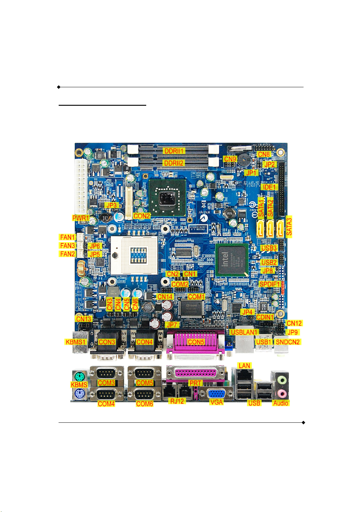
1.3 Configuration
1.3.1 Layout of TOP
PS960GLE/ PS965GME Mainboard
5
Page 10
PS960GLE/ PS965GME Mainboard
1.4 Hardware Installation
This section will assist you in quickly installing your system hardware. Wear a wrist ground strap
before handling components. Electrostatic discharge may damage the system's components.
Jumpers
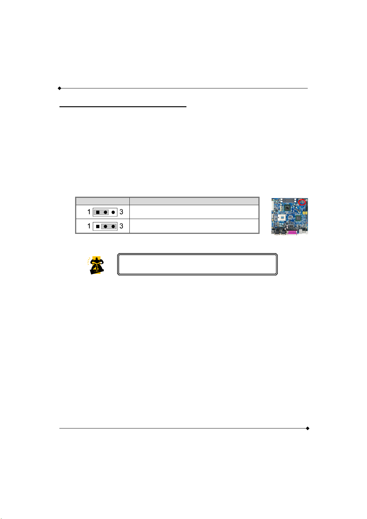
1.4.1 JP1: Clear CMOS Jumper
The "Clear CMOS" function is used when you are unable boot your system and need to reset the
BIOS settings (CMOS settings) back to the manufacturer's original settings. This is also a way to
reset the system password if you have forgotten it.
JP1 Assignment
Note: "Closed" means putting a jumper cap onto two adjacent header pins.
1. Turn off your system and disconnect the AC power cable.
Pin 1-2 Closed
Normal (Default)
Pin 2-3 Closed
Clear CMOS Data
The following steps explain how to reset your CMOS
configurations when you forgot a system password.
2. Set JP1 header to OFF (2-3 Closed).
3. Wait several seconds.
4. Set JP1 header to ON (1-2 closed).
5. Connect the AC power cable and turn on your system.
6. Reset your new password.
6
Page 11
PS960GLE/ PS965GME Mainboard
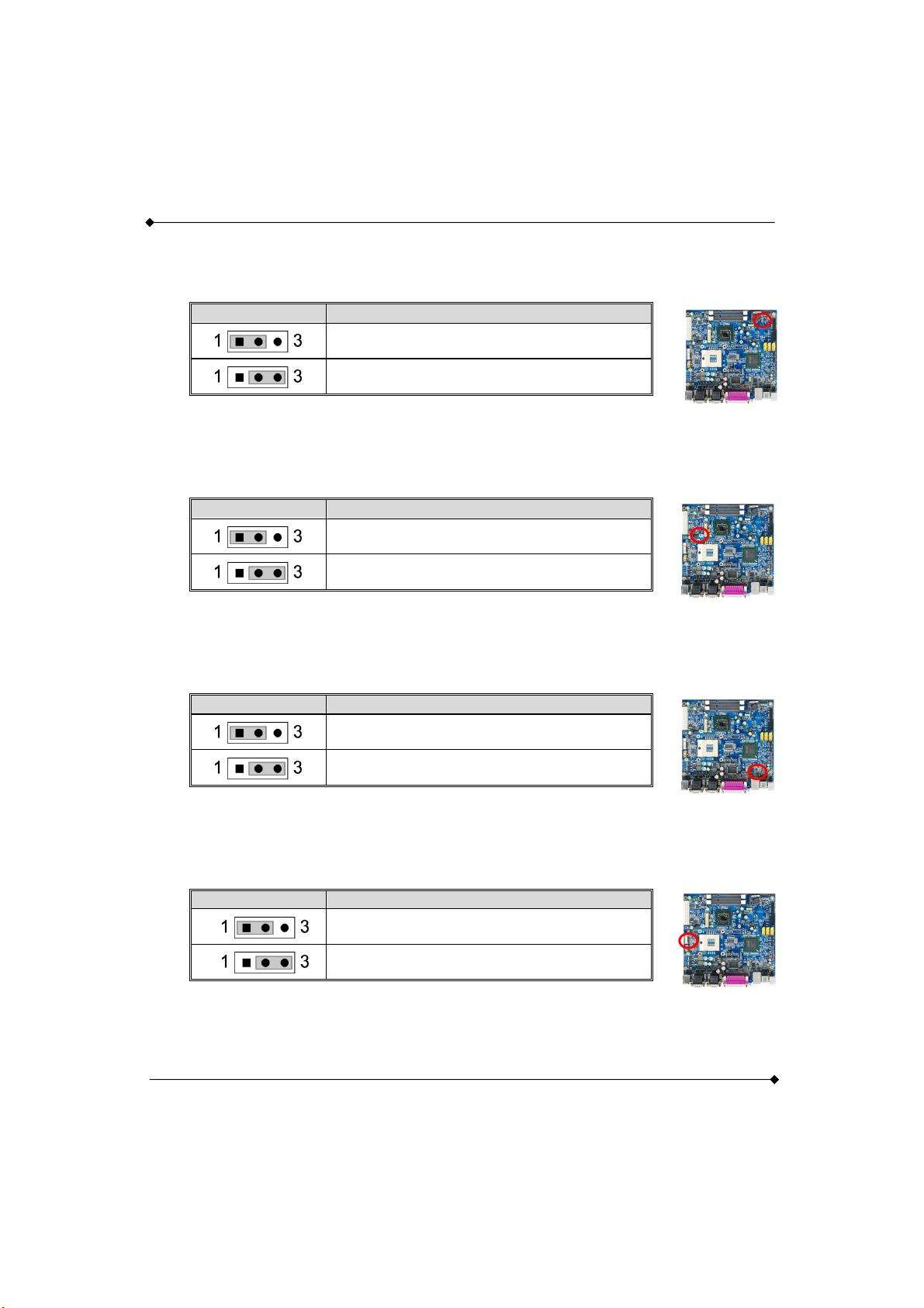
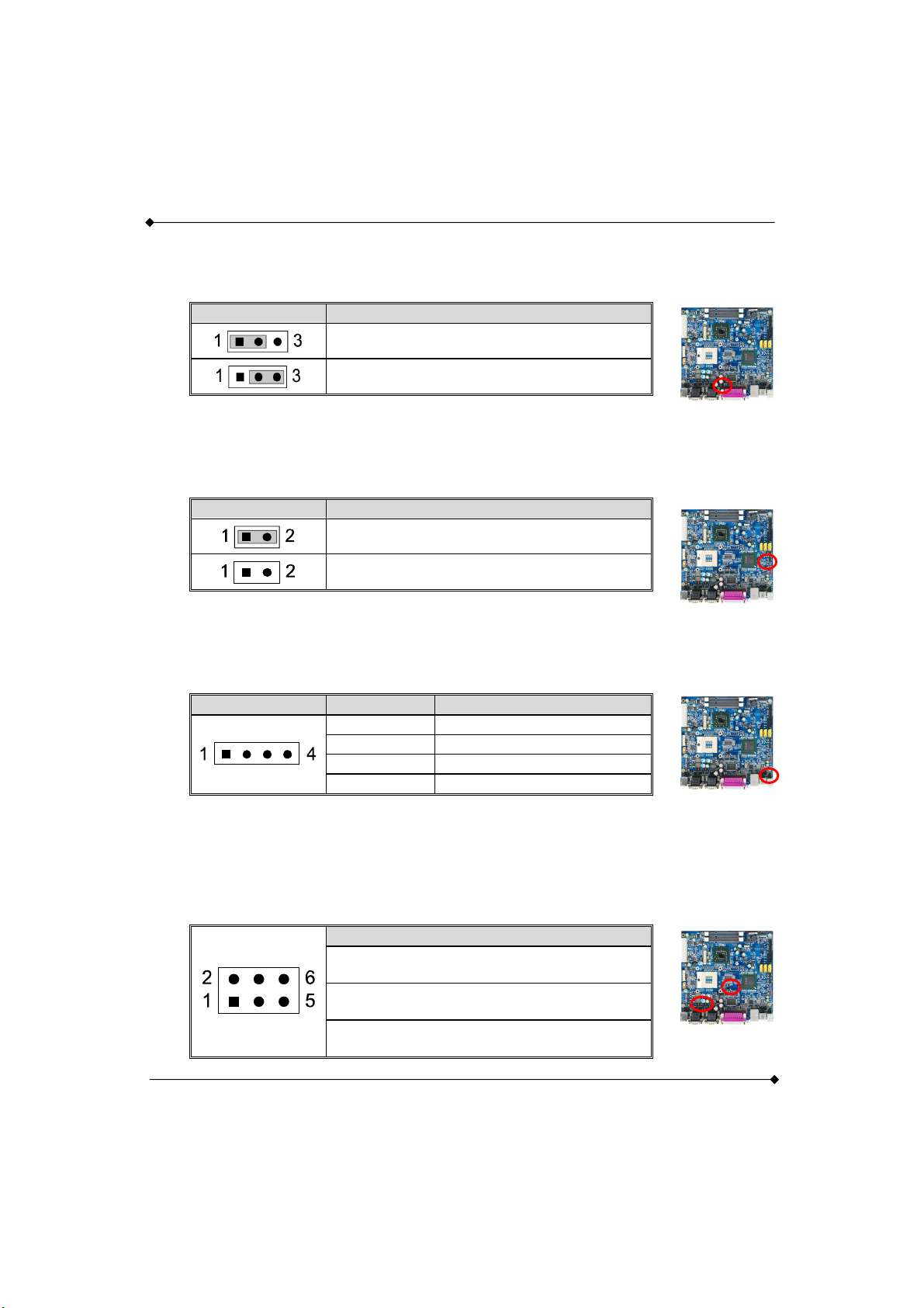
1.4.2 JP2: CF Card Master/ Slave Jumper
This Jumper is to select the CF works on Secondary Channel master device or Slave device.
JP2
Assignment
Pin 1-2 Closed
Slave (Default)
Pin 2-3 Closed
Master
1.4.3 JP3: LVDS VDD POWER
It’s for LVDS VDD power setting.
JP3
Assignment
Pin 1-2 Closed
5V
Pin 2-3 Closed
3V (Default)
1.4.4 JP4: USB POWER
+5V or +5V STB for USB
JP4
Assignment
Pin 1-2 Closed
5V (Default)
Pin 2-3 Closed
5V STB
1.4.5 JP5/ JP6: FAN Power
This is a 3-pin header for the fan. JP5 is for Fan2, JP6 is for Fan3.
JP5/ JP6 Assignment
Pin 1-2 Closed
12V (Default)
Pin 2-3 Closed
5V
7
Page 12
1.4.6 JP7: RJ12 POWER
It’s for RJ12 power setting.
PS960GLE/ PS965GME Mainboard
JP7
Assignment
Pin 1-2 Closed
24V (Default)
Pin 2-3 Closed
12V
1.4.7 JP8: MINI PCI ON/OFF
It’s for MINI PCI ON/OFF setting.
JP8
Assignment
Pin 1-2 Closed
OFF
Pin 1-2 Open
On (Default)
1.4.8 JP9: EXT. Audio
It’s for EXT. Audio setting.
JP9
Pin
1 CON_R
2 CON_L
3 +5V
4 GND
Assignment
1.4.9 CN1 - 6: RS-232 Voltage Setting
It’s for RS-232 Voltage setting. The correspondence between CN# & COM# is below:
CN1ÆCOM1, CN2ÆCOM2, CN3ÆCOM4, CN4ÆCOM3, CN5ÆCOM6, CN6ÆCOM5.
Assignment
Pin 1-2 Closed
+5V
Pin 3-4 Closed
RINGW(Default)
Pin 5-6 Closed
+12V
8
Page 13
PS960GLE/ PS965GME Mainboard
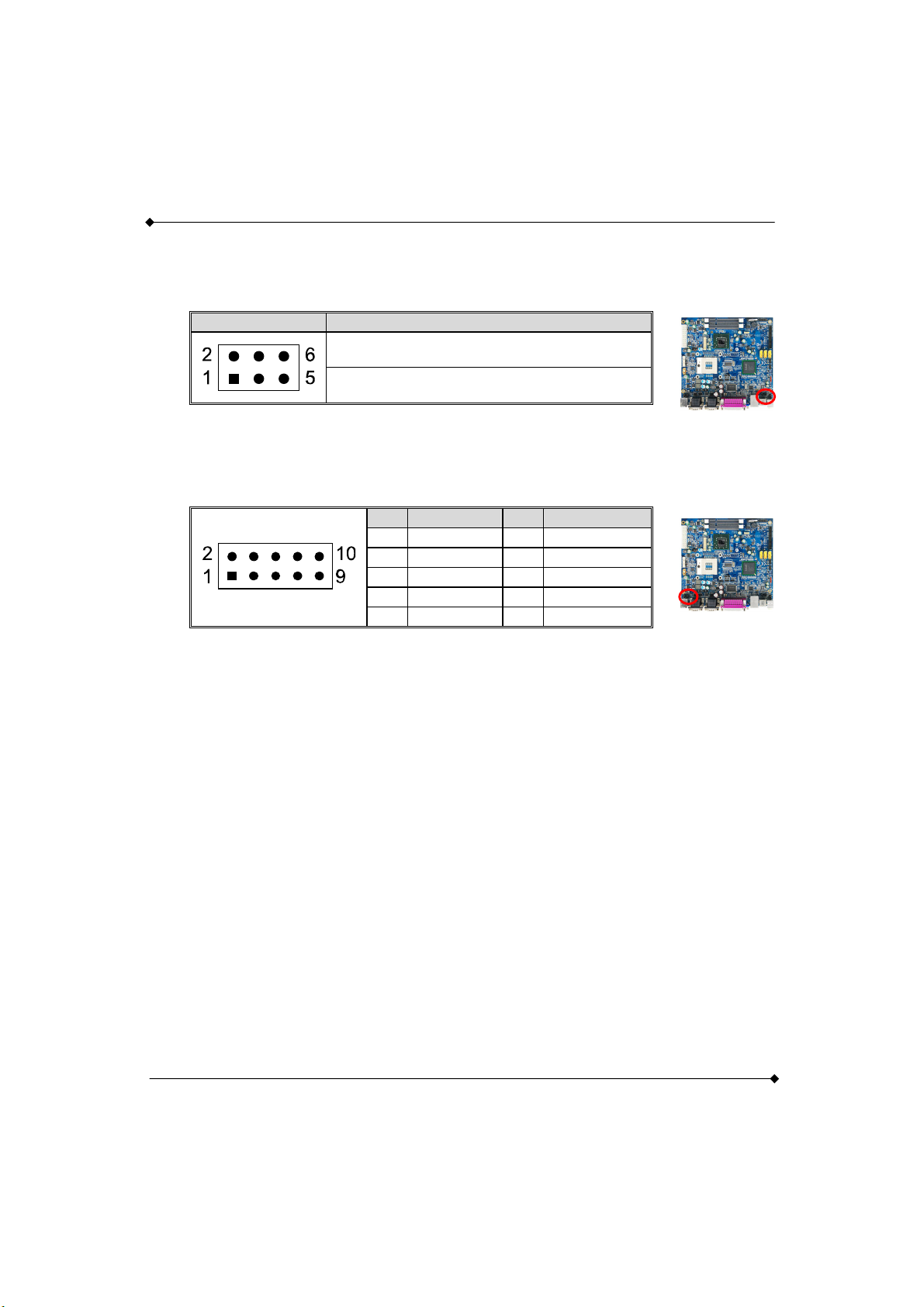
1.4.10 CN12: AUDIO OUTPUT SELECT
It’s for audio output select setting.
CN12
The default setting is “Pin 1-3 & 2-4 Closed“.
Assignment
Pin 1-3 & 2-4 Closed
Audio Connector
Pin 3-5 & 4-6 Closed
JP9
1.4.11 CN13: KB/MS
The following table shows the pin outs of the INT_KBMS connectors.
Pin Assignment Pin Assignment
1 KBDATA_C 2 KBDATA
3 KBCLK_C 4 KBCLK
5 +5V 6 GND
7 MSDATA_C 8 MSDATA
9 MSCLK_C 10 MSCLK
The default setting is “Pin 1-2, 3-4, 7-8, 9-10 Closed“.
9
Page 14
PS960GLE/ PS965GME Mainboard
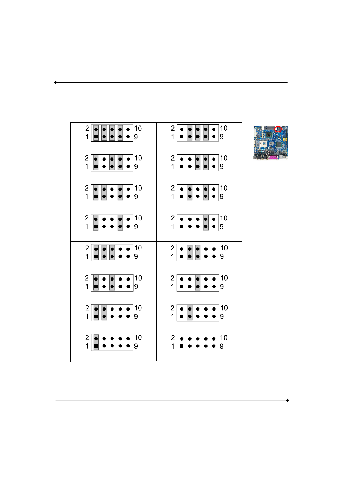
1.4.12 CN9: LVDS Selection
The LCD panel, inverter for LCD LAMP, Touch-screen Serial Interface must be connected to this
LVDS header, using the below described connector:
ID 0 1024x768x24(Dual) ID 1 1280x1024x24(Dual)
ID 2(default) 1024x768x24(Single)
ID 4 640x480x18(Single)
ID 6 800x600x18(Single)
ID 8 1024x768x18(Dual)
ID 3 1600x1200x18(Single)
ID 5 640x480x24(Single)
ID 7 1024x768x18(Single)
ID 9 1280x768x18(Single)
ID 10 1280x768x24(Single) ID 11 1280x800x18(Dual)
ID 12 1366x768x18(Single)
ID 13 1400x1050x18(Dual)
ID 14 1440x900x18(Single) ID 15 D-Sub only
10
Page 15
PS960GLE/ PS965GME Mainboard
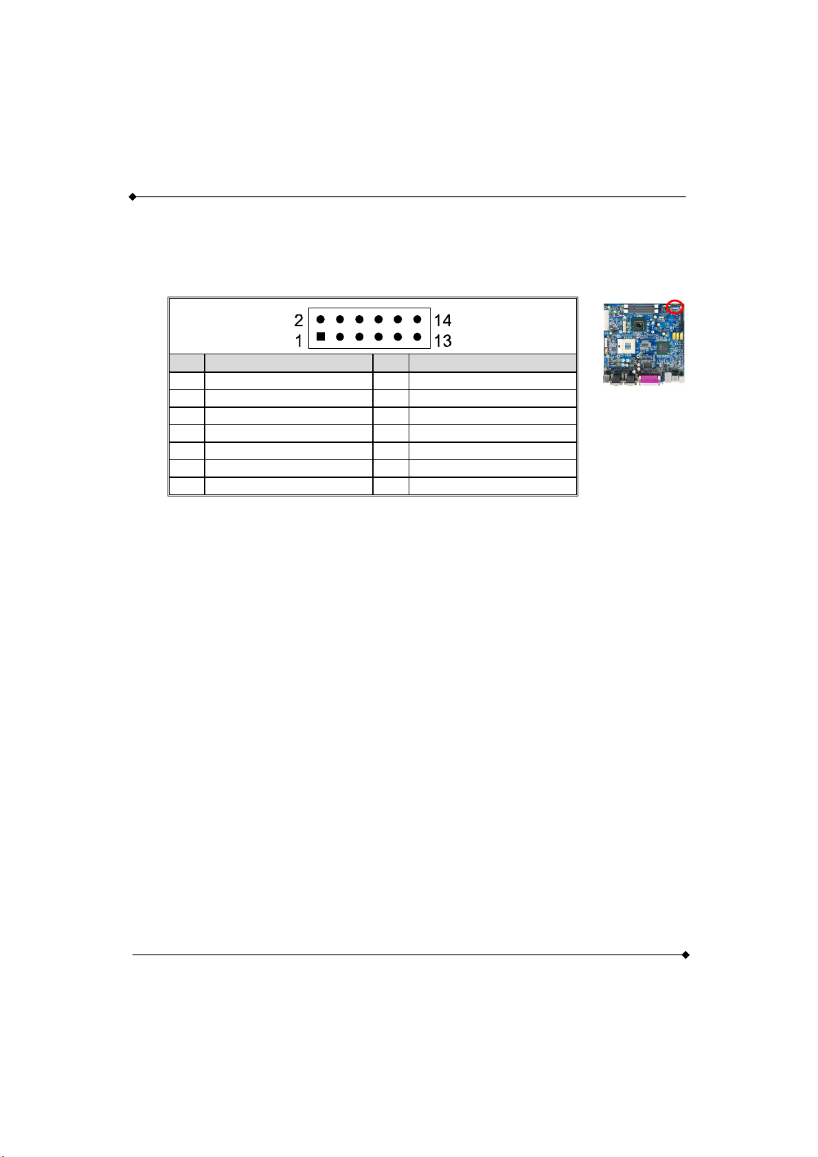
1.4.13 CN8 FPSWLED: Front Panel Headers
This 16-pin connector includes Power-on, Reset, HDD LED, Power LED, and speaker connection.
It allows user to connect the PC case’s front panel switch functions.
Pin Assignment Pin Assignment
1 N/C 2 N/C
3 EXTRST- 4 GND
5 PWRLED+ 6 PWRLED-
7 HDD LED+ 8 HDD LED-
9 PWRBTI 10 PWRBTI11 ACT LED+ 12 ACT LED-
13 SPEED LED+ 14 SPEED LED-
11
Page 16
PS960GLE/ PS965GME Mainboard
Connectors
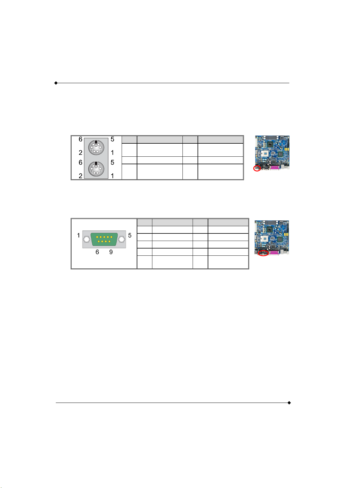
1.4.14 KBMS1: Mini-DIN PS/2 Port
This mainboard provides a standard Mini-DIN PS/2 port to connect PS/2 keyboard and mouse.
Pin Assignment Pin Assignment
1
Keyboard/
Mouse data
3 GND 4 5V
5
Keyboard/
Mouse clock
2 N/C
6 GND
1.4.15 CON3/ CON4: COM3/ 4/ 5/ 6 Port
A 9-pin D-Sub male connector is the serial port. The following table shows its pin assignments.
Pin Assignment Pin Assignment
1 DCD 2 SIN
3 SOUT 4 DTR
5 GND 6 DSR
7 RTS 8 CTS
9
+5V/RINGW/
+12V
12
Page 17
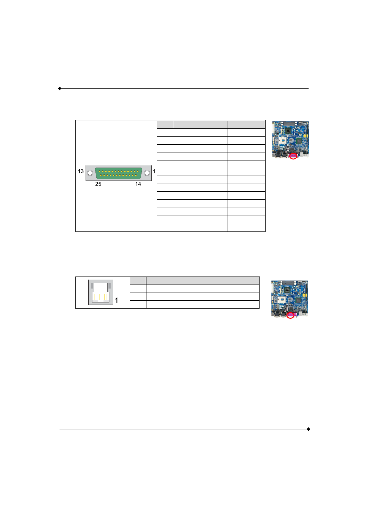
1.4.16 PRT1: LPT PORT
The following table shows its pin assignments.
1.4.17 RJ12
The following table shows its pin assignments.
PS960GLE/ PS965GME Mainboard
Pin Assignment Pin Assignment
1 RSTB- 14 RAFD2 RPDR0 15 P_ERR-
3 RPDR1 16 RINIT_P4 RPDR2 17 RSLIN5 RPDR3 18 GND
6 RPDR4 19 GND
7 RPDR5 20 GND
8 RPDR6 21 GND
9 RPDR7 22 GND
10 P_ACK- 23 GND
11 P_BUSY 24 GND
12 P_PE 25 GND
13 P_SLCT
Pin Assignment Pin Assignment
1 GND 2 GND
3 Sensor_IN 4 24V/12V
5 N/C 6 Sensor_IN
13
Page 18

PS960GLE/ PS965GME Mainboard
1.4.18 VGA1: VGA Connector
The mainboard provides one VGA connector (= D-Sub connector) on back panel.
VGA connector (= D-Sub connector) delivers the analogy signals, and is able to connect with
traditional CRT display, flat display, or other display device which with the D-Sub interface
compatible.
Pin Assignment
1 RED
2 GREEN
3 BLUE
4 N/A
5 GND
6 GND
7 GND
8 GND
9 NVGA03
10 GND
11 N/A
12 DDC_DATA
13 5VHSYNC
14 5VVSYNC
15 DDC_CLK
1.4.19 LAN1: LAN Port
There is one PCI-E Realtek® Giga Ethernet LAN port available for you to attach Internet cables
14
Page 19

PS960GLE/ PS965GME Mainboard
1.4.20 USB1: USB Port
There are 4 USB 2.0/ 1.1 ports. These USB ports are used to attach with USB devices, such as
keyboard, mouse and other USB supported devices.
1.4.21 SNDCN2
1.4.22 COM1/ COM2: COM Port
This mainboard provides four COM pin headers for you to connect additional serial connectors on
your case back panel. Attach cables of serial connectors onto these headers, then you can use
the serial connectors connecting with a mic, modem or other peripheral device.
Pin Assignment Pin Assignment
1 DCD 2 SIN
3 SOUT 4 DTR
5 GND 6 DSR
7 RTS 8 CTS
9
+5V/RINGW/
+12V
15
10 N/C
Page 20

1.4.23 CN14: 8-bit GPIO
8-bit General Purpose Input/Output
Pin Assignment Pin Assignment
1 DIO_0 2 DIO_1
3 DIO_2 4 DIO_3
5 DIO_4 6 DIO_5
7 DIO_6 8 DIO_7
9 GND 10 +5V
1.4.24 CDIN1
Pin Assignment
CDL
1
CDG
2
CDG
3
CDR
4
PS960GLE/ PS965GME Mainboard
1.4.25 SPDIF
S/PDIF specifies a Data Link Layer protocol and choice of Physical Layer specifications for
carrying digital audio signals between devices and stereo components over either optical or
electrical cable.
Pin Assignment
5V
1
N/A
2
3
4
5
SPDIFO
GND
N/C
16
Page 21

PS960GLE/ PS965GME Mainboard
1.4.26 USB2/ USB3: USB Connector
These USB ports are used to attach with USB devices, such as keyboard, mouse and other USB
supported devices.
Pin Assignment Pin Assignment
1 N/C 2 VCC
3 GND 4 DA-
5 DB+ 6 DA+
7 DB- 8 GND
9 VCC 10 N/C
1.4.27 SATA1/ SATA2/ SATA3
Pin Assignment
GND
1
SATA_TX+
2
SATA_TX-
3
GND
4
5
6
7
SATA_RX+
SATA_RXGND
1.4.28 IDE1: Mini-IDE Connector
The mainboard provides one Mini-IDE connector that supports Ultra ATA 100/ 66/ 33 Mini-IDE
device. You can attach a maximum of two Mini-IDE devices, such as hard disk drive (HDD),
CD-ROM, DVD-ROM, etc. using Mini-IDE ribbon cables.
In general, two Mini-IDE devices can be attached onto one Mini-IDE connector. If you attach two
Mini-IDE HDDs, you must configure one drive as the master and the other one as the slave.
17
Page 22

1.4.29 CON2: LVDS
Pin Assignment Pin Assignment
2 +12V/+5V 1 +12V/+5V
4 GND 3 GND
6 LCDVDD 5V/3.3V 5 LCDVDD 5V/3.3V
8 GND 7 GND
10 BCKLITE_ON 9 BRIGHTNES
12 LVDS_GND 11 LVDS_GND
14 CHB_TX0+ 13 CHA_TX0+
16 CHB_TX0- 15 CHA_TX0-
18 LVDS_GND 17 LVDS_GND
20 CHB_TX1+ 19 CHA_TX1+
22 CHB_TX1- 21 CHA_TX1-
24 LVDS_GND 23 LVDS_GND
26 CHB_TX2+ 25 CHA_TX2+
28 CHB_TX2- 27 CHA_TX2-
30 LVDS_GND 29 LVDS_GND
32 CHB_TXC+ 31 CHA_TXC+
34 CHB_TXC- 33 CHA_TXC-
36 LVDS_GND 35 LVDS_GND
38 CHB_TX3+ 37 CHA_TX3+
40 CHB_TX3- 39 CHA_TX3-
PS960GLE/ PS965GME Mainboard
18
Page 23

PS960GLE/ PS965GME Mainboard
1.4.30 DDRII1/ DDRII2: Memory Installation
The PS960GLE/ PS965GME provides the DDR II SO-DIMM socket which allows you to install
200-pin SO-DIMM.
Memory Installation Steps
1. Match the notch on the bottom of the DIMM module with the corresponding pattern in the
DIMM slot. This will ensure that the module will be inserted with the proper orientation.
Now the chips or pins at the bottom of the DIMM module are still visible.
2. Lower the DIMM module into the DIMM Slot until the chips or pins at the bottom of the
DIMM module are hidden.
3. Press the DIMM module backward firmly using both thumbs until the module snaps into
place. Do not use excessive force.
4. Repeat steps 1, 2 & 3 for the remaining DIMM slots.
* The pictures above are for reference only. Your actual installation may vary
slightly from the pictures.。
19
Page 24

PS960GLE/ PS965GME Mainboard
1.4.31 PWR1: ATX Power Connector
This mainboard provides one ATX connector. You must attach it before the system is powered on.
This power connector supports several power management functions such as the instant
power-on function. The connector pins are described below.
Pin Assignment Pin Assignment
13 3.3V 1 3.3V
14 -12V 2 3.3V
15 COM 3 COM
16 PS-ON 4 +5V
17 COM 5 COM
18 COM 6 +5V
19 COM 7 COM
20 -5V 8 PWR-OK
21 +5V 9 5VSB
22 +5V 10 12V
23 +5V 11 12V
24 COM 12 3.3V
1.4.32 FAN1/ FAN2/ FAN3: FAN Header
There is one fan header available for cooling fan. This cooling fan plays an important role in
maintaining ambient temperatures in your system.
Assignment
Pin
1 GND
2 +12V
3 FAN RPM
20
Page 25

PS960GLE/ PS965GME Mainboard
1.4.33 MINI_PCI1: Mini PCI Slot
Mini PCI (Peripheral Component Interconnect) is a 32-bit, 33MHz bus standard for integrated
peripherals of smaller products. The mainboard provides one Mini PCI slot available to install
expansion cards such as network card, SCSI card, etc.
2
1
1.4.34 CON1: CF Card Connector
The mainboard provides one CF card connector (CompactFlash I/II Card).
21
Page 26

PS960GLE/ PS965GME Mainboard
2.3 Main Menu
The Award BIOS (Basic Input/Output System) installed in your computer system’s.
The BIOS provides for a standard device such as disk drives, serial ports and parallel ports. It
also adds password protection as well as special support for detailed fine-tuning of the chipset
controlling the entire system.
The Award BIOS provides a Setup utility program for specifying the system configurations and
settings. The BIOS ROM of the system stores the Setup utility.
When you turn on the computer, the Award BIOS is immediately activated. Pressing the <Del>
key immediately allows you to enter the Setup utility. If you a little bit late press the <Del> key,
POST (Power On Self Test) will continue with its test routines, thus preventing you from invoking
the Setup. If you still wish to enter Setup, restart the system by pressing the “Reset” button or
simultaneously pressing the <Ctrl>, <Alt> and <Delete> keys. You can also restart by turning the
system Off and back On again.
The following message will appear on the screen:
Press <DEL> to Enter Setup
In general, you press the arrow keys to highlight items, <Enter> to select, the <PgUp> and
<PgDn> keys to change entries, <F1> for help and <Esc> to quit. When you enter the Setup utility,
the Main Menu screen will appear on the screen. The Main Menu allows you to select from
various setup functions and exit choices.
22
Page 27

2.3.1 Standard CMOS Features
Include all the adjustable items in standard compatible BIOS.
PS960GLE/ PS965GME Mainboard
“Standard CMOS Features” allows you to record some basic hardware configurations in your
computer system and set the system clock and error handling. If the CPU card is already installed
in a working system, you will not need to select this option.
You will need to run the Standard CMOS option, however, if you change your system hardware
configurations, such as onboard battery fails, or the configuration stored in the CMOS memory
was lost or damaged.
Date
The date format is: Day : Sun to Sat
Month : 1 to 12
Date : 1 to 31
Year : 1999 to 2099
23
Page 28

PS960GLE/ PS965GME Mainboard
Time
The time format is: Hour : 00 to 23
Minute : 00 to 59
Second : 00 to 59
To set the date & time, highlight the “Date” & “Time” and use the <PgUp>/ <PgDn> or +/- keys to
set the current time.
IDE Channel 0 Master/ Slave
The onboard PCI IDE connectors provide Primary and Secondary channels for connecting up to
four IDE hard disks or other IDE devices.
Each channel can support up to two hard disks; the first is the “Master” and the second is the
“Slave”.
Press <Enter> to configure the hard disk. The selections include Auto, Manual, and None. Select
“Manual” to define the drive information manually.
You will be asked to enter the following items.
Cylinder: Number of cylinders
Head: Number of read/write heads
Precomp: Write precompensation
Landing Zone: Landing zone
Sector: Number of sectors
The Access Mode selections are as follows:
CHS (HD < 528MB)
LBA (HD > 528MB and supports Logical Block Addressing)
Large (for MS-DOS only)
Auto
24
Page 29

PS960GLE/ PS965GME Mainboard
Video
This field selects the type of video display card installed in your system.
You can choose the following video display cards:
EGA/VGA For EGA, VGA, SEGA, SVGA or PGA monitor adapters. (default)
CGA 40 Power up in 40 column mode.
CGA 80 Power up in 80 column mode.
MONO For Hercules or MDA adapters.
Halt On
This field determines whether or not the system will halt if an error is detected during power up.
All errors
Whenever the BIOS detects a non-fatal error, the system will stop and you will be prompted.
No errors
The system boot will not be halted for any error that may be detected.
All, But Keyboard (default)
The system boot will not be halted for a keyboard error; it will stop for all other errors.
All, But Diskette
The system boot will not be halted for a disk error; it will stop for all other errors.
All, But Disk/Key
The system boot will not be halted for a keyboard or disk error; it will stop for all others.
25
Page 30

PS960GLE/ PS965GME Mainboard
2.3.2 Advanced BIOS Features
Include all the adjustable items of Award special enhanced features.
CPU Feature
Press Enter to configure the settings relevant to CPU Feature.
Removable Device Priority
Press Enter to configure the settings relevant to Removable Device Priority.
Hard Disk Boot Priority
It allows you to set the priority for hard disk boot. When you press enter, the selections shows the
current hard disks used in your system as well as the “Bootable Add-in Card” that is relevant to
other boot sources media such as SCSI cards and LAN cards.
26
Page 31

PS960GLE/ PS965GME Mainboard
CD-ROM Boot Priority
Press Enter to configure the settings relevant to CD-ROM Boot Priority.
Network Boot Priority
Press Enter to configure the settings relevant to Network Boot Priority.
Virus Warning
If enabled, an alarm message will be displayed when trying to write on the boot sector or on the
partition table on the disk, which is typical of the virus.
CPU L3 Cache
It allows you to activate the CPU L3 Cache.
Setting: Disabled, Enabled (Default).
Hyper-Threading Technology
If enabled, when your processor supports Hyper-Threading Technology.
Quick Power On Self Test
Setting: Disabled, Enabled (Default).
First/ Second/ Third Boot Device
These fields determine the drive that the system searches first for an operating system. The
options available include Setting: Removable, Hard Disk, CDROM, Network and Disabled.
27
Page 32

PS960GLE/ PS965GME Mainboard
Boot Other Device
It allows the system to search for an OS from other devices other than the ones selected in the
First/ Second/ Third Boot Device.
Setting: Disabled, Enabled (Default).
Boot Up NumLock Status
It allows you to activate the NumLock function after you power up the system.
Setting: Off, On (Default).
Gate A20 Option
Setting: Normal, Fast (Default).
Typematic Rate Setting
When disabled, continually holding down a key on your keyboard will generate only one instance.
When enabled, you can set the two typematic controls listed at the next.
Setting: Disabled (Default), Enabled.
Typematic Rate (Chars/Sec)
When the typematic rate is enabled, the system registers repeated keystrokes speeds.
Setting: 6 to 30 characters per second.
Typematic Delay (Msec)
When the typematic rate is enabled, this item allows you to set the time interval for displaying the
first and second characters.
Setting: 250 (Default), 500, 750, 1000.
28
Page 33

PS960GLE/ PS965GME Mainboard
Security Option
It allows you to limit access to the System and Setup.
When you select System, the system prompts for the User Password every time you boot up.
When you select Setup, the system always boots up and prompts for the Supervisor Password
only when the Setup utility is called up.
Setting: Setup (Default), System.
APIC Mode
APIC stands for Advanced Programmable Interrupt Controller.
Setting: Disabled, Enabled (Default).
MPS Version Control For OS
Setting: 1.1, 1.4 (Default).
OS Select For DRAM > 64MB
Setting: Non-OS2 (Default), OS2.
Delay For HDD (Secs)
Setting: 0-15.
Full Screen LOGO Show
Setting: Disabled (Default), Enabled.
29
Page 34

PS960GLE/ PS965GME Mainboard
Small Logo(EPA) Show
The EPA logo appears at the right side of the monitor screen when the system is boot up.
Setting: Disabled (Default), Enabled.
Summary Screen Show
Setting: Disabled, Enabled (Default).
30
Page 35

2.3.3 Advanced Chipset Features
Include all the adjustable items of chipset special features.
PS960GLE/ PS965GME Mainboard
DRAM Timing Selectable
It refers to the method by which the DRAM timing is selected.
Setting: Manual, By SPD (Default).
CAS Latency Time
It allows CAS latency time in HCLKs as Auto, 3, 4, 5, 6 and 7. The system board designer should
set the values in this field, depending on the DRAM installed. Do not change the values in this
field unless you change specifications of the installed DRAM or CPU.
Setting: Auto (Default), 3, 4, 5, 6, 7.
31
Page 36

PS960GLE/ PS965GME Mainboard
DRAM RAS# to CAS# Delay
It allows you to insert a delay between the RAS (Row Address Strobe) and CAS (Column Address
Strobe) signals. This delay occurs when the SDRAM is written to, read from or refreshed.
Reducing the delay improves the performance of the SDRAM.
Setting: Auto (Default), 2, 3, 4, 5, 6.
DRAM RAS# Precharge
It sets the number of cycles required for the RAS to accumulate its charge before the SDRAM
refreshes.
Setting: Auto (Default), 2, 3, 4, 5, 6.
Precharge Delay (tRAS)
Setting: Auto (Default), 8 - 15.
System Memory Frequency
It allows you to set the frequency of the DRAM memory
Setting: By SPD (Default), 533MHz, 667MHz.
System BIOS Cacheable
The setting of Enabled allows caching of the system BIOS ROM at F000hFFFFFh for better
system performance. However, if any program writes to this memory area, a system error may
result.
Setting: Disabled, Enabled (Default).
32
Page 37

PS960GLE/ PS965GME Mainboard
Memory Hole At 15M-16M
In order to improve performance, certain space in memory can be reserved for ISA cards. This
memory must be mapped into the memory space below 16 MB.
Setting: Disabled (Default), Enabled.
On-Chip Frame Buffer Size
Setting: 1MB, 8MB (Default).
DVMT Mode
Setting: FIXED, DVMT (Default).
DVMT/FIXED Memory Size
Setting: 128MB (Default), 256MB, Max.
Boot Display
Setting: Auto, CRT, LFP, CRT+LFP (Default).
Panel Scaling
Setting: Auto (Default), On, Off.
Panel Brightness
Setting: 8 (Default), selection is 0-15.
33
Page 38

2.3.4 Integrated Peripherals
Include all onboard peripherals.
PS960GLE/ PS965GME Mainboard
OnChip IDE Device >>>
IDE HDD Block Mode
It allows HDD controller to use the fast block mode to transfer data to and from HDD.
Setting: Disabled, Enabled (Default).
34
Page 39

PS960GLE/ PS965GME Mainboard
On-Chip Primary/Secondary PCI IDE
The integrated peripheral controller contains an IDE interface with support for two IDE channels.
Select Enabled to activate each channel separately.
Setting: Disabled, Enabled (Default).
IDE Primary Master/Slave PIO
It allows your system HDD controller to run faster.
Rather than having the BIOS issue with a series of commands that transferring to or from the disk
drive, PIO (Programmed Input/Output) allows the BIOS to communicate with the controller and
CPU directly.
When Auto is selected, the BIOS will select the best available mode.
Setting: Auto (Default), Mode 0, Mode 1, Mode 2, Mode 3, Mode 4.
IDE Primary Master/Slave UDMA
It allows your system to improve disk I/O throughput to 33MB/sec with the Ultra DMA33 feature.
Setting: Disabled, Auto.
SATA Mode
Setting: IDE (Default), RAID, AHCI, Disabled
LEGACY Mode Support
Setting: Disabled (Default), Enabled.
35
Page 40

Onboard Device >>>
Audio Device
Setting: Enabled (Default), Disabled.
Onboard Lan Controller
Setting: Enabled (Default), Disabled.
SuperIO Device >>>
PS960GLE/ PS965GME Mainboard
Onboard Serial/Parallel Port
It allows you to select the onboard serial and parallel ports with their addresses.
Setting: Serial Port 1 3F8/IRQ4 (Default)
Serial Port 2 2F8/IRQ3 (Default)
Serial Port 3 3E8/IRQ4 (Default)
Serial Port 4 2E8/IRQ3 (Default)
Serial Port 5 3E0/IRQ4 (Default)
Serial Port 6 2E0/IRQ3 (Default)
Parallel Port 378/IRQ7 (Default)
36
Page 41

Parallel Port Mode
Setting: Standard (Default)
EPP1.9+SPP
ECP
ECP+EPP1.9
Printer
EPP1.7+SPP
ECP+EPP1.7
ECP Mode Use DMA
Setting: 1, 3 (Default).
PWRON After PWR-Fail
PS960GLE/ PS965GME Mainboard
It sets the system power status whether on or off when power returns to the system from a power
failure situation.
Setting: Off, On, Former-Sts (Default).
37
Page 42

USB Device Setting >>>
USB 1.0 Controller
Setting: Disabled, Enabled (Default).
USB 2.0 Controller
PS960GLE/ PS965GME Mainboard
For using USB 2.0, it is necessary OS drivers must be installed first. Please update your system
to at least Windows 2000 SP4 or Windows XP SP2.
Setting: Disabled, Enabled (Default).
USB Operation Mode
Setting: Full/Low Speed, High Speed (Default)
USB Keyboard Function
Setting: Disabled, Enabled (Default).
38
Page 43

USB Mouse Function
Setting: Disabled, Enabled (Default).
USB Storage Function
Setting: Disabled, Enabled (Default).
PS960GLE/ PS965GME Mainboard
39
Page 44

2.3.5 Power Management Setup
Include all the adjustable items of Green function features.
PS960GLE/ PS965GME Mainboard
ACPI Function
It supports ACPI (Advance Configuration and Power Interface).
Setting: Enabled (Default), Disabled.
ACPI suspend Type
Setting: S1(POS) (Default), S3(STR), S1&S3.
40
Page 45

PS960GLE/ PS965GME Mainboard
Power Management
It allows you to select the type of power saving management modes.
Setting:
User Define Each of the ranges is from 1 min. to 1hr.
Except for HDD Power Down which ranges from 1 min. to 15 min
Min Saving (Default) Minimum power management
Max Saving Maximum power management
Video Off Method
It defines the Video Off features.
Setting:
Blank Screen Writes blanks to the video buffer
V/H SYNC+Blank Blank the screen and turn off vertical and horizontal scanning
DPMS (Default) Allowing BIOS to control the video display.
Video Off In Suspend
When enabled, the video is off in suspending mode.
Setting: No, Yes (Default).
Suspend Type
Setting: Stop Grant (Default), PwrOn Suspend.
41
Page 46

Suspend Mode
PS960GLE/ PS965GME Mainboard
When “Enabled”, after the set time of system inactivity, all devices except the CPU will be shut off
as the set time.
Setting: Disabled (Default), 1 Min, 2 Min, 4 Min, 8 Min, 12 Min, 20 Min, 30 Min, 40 Min, 1 Hour.
HDD Power Down
When “Enabled”, after the set time of system inactivity, the hard disk drive will be powered down
while all other devices remain active.
Setting: Disabled (Default), 1 Min - 15 Min.
42
Page 47

PS960GLE/ PS965GME Mainboard
Soft-Off by PWR-BTTN
It defines the power-off mode when using an ATX power supply.
In the Instant Off mode, it allows powering off immediately upon pressing the power button.
In the Delay 4 Sec mode, the system powers off when the power button is pressed for more than
4 seconds or enters the suspend mode when pressed for less than 4 seconds.
Setting: Instant-off (Default), Delay 4 Sec. .
Power On by Ring
It enables or disables the power on of the system through the modem connected or LAN.
Setting: Disabled (Default), Enabled.
Resume by Alarm
It enables or disables the resumption of the system operation. When enabled, the user is allowed
to set the Date and Time.
Setting: Disabled (Default), Enabled.
Reload Global Timer Events
The HDD and PCI PIRQ are I/O events that can prevent the system from entering a power saving
mode or can awaken the system from such a mode. When an I/O device wants to gain the
attention of the operating system, it signals this by causing an IRQ to occur. When the operating
system is ready to respond to the request, it interrupts itself and performs the service.
43
Page 48

2.3.6 PnP/PCI Configurations
Include all configurations of PCI and PnP resources.
PS960GLE/ PS965GME Mainboard
Init Display First
Setting: PCI Slot (Default), Onboard.
PCI/VGA Palette Snoop
Some non-standard VGA display cards may not show colors properly.
It allows you to set whether or not MPEG VGA cards can display with PCI/VGA.
When “Enabled”, a PCI/VGA can display with an MPEG VGA card.
When “Disabled”, a PCI/VGA cannot display with an MPEG VGA card.
Setting: Disabled (Default), Enabled.
Maximum Payload Size
Setting: 128 (Default), 256, 512, 1024, 2048, 4096.
44
Page 49

PS960GLE/ PS965GME Mainboard
2.3.7 PC Health Status
It is for monitoring the system status such as temperature, voltage, and fan speeds.
CPU smart Fan Temperature
Setting: Disabled, 40℃/104°F, 4 5 ℃/113°F, 5 0 ℃/122°F (Default).
Smart Fan Tolerance Value
Setting: Min. is 1, Max. is 5.
Current System Temperature
Current CPU Temperature
System FAN Speed
CPU FAN Speed
Vcore
45
Page 50

2.3.8 Frequency/Voltage Control
It can load Frequency/ Voltage Control setup.
PS960GLE/ PS965GME Mainboard
Spread Spectrum
It sets the value of the spread spectrum. It is for CE testing use only.
Setting: Disabled, Enabled (Default).
46
Page 51

2.3.9 Load Fail-Safe Defaults
It can load Fail-Safe defaults except standard CMOS setup.
PS960GLE/ PS965GME Mainboard
47
Page 52

PS960GLE/ PS965GME Mainboard
2.3.10 Load Optimized Defaults
It can load the preset system parameter values to set the system in its best performance
configurations.
48
Page 53

PS960GLE/ PS965GME Mainboard
2.3.11 Set Password
Set change or disable password. It allows you to limit access to the system and/or BIOS setup.
Useing Password to set a password that will be used exclusively on the system. To specify a
password, highlight the type you want and press <Enter>.
The Enter Password: message prompts on the screen. Type the password, up to eight characters
in length, and press <Enter>. And the system confirms your password by asking you to type it
again. After setting a password, the screen automatically returns to the main screen.
To disable a password, just press the <Enter> key when you are prompted to enter the password.
A message will confirm the password to be disabled. Once the password is disabled, the system
will boot, then you can enter BIOS Setup freely.
49
Page 54

2.3.12 Save & Exit Setup
Save CMOS value settings to CMOS and exit setup.
PS960GLE/ PS965GME Mainboard
Typing “Y”, you will quit the setup utility and save all the changes into the CMOS memory.
Typing “N”, you will return to Setup utility.
50
Page 55

2.3.13 Exit Without Saving
Abandon all CMOS value changes and exit setup.
PS960GLE/ PS965GME Mainboard
Typing “Y” will quit the Setup utility without saving the modifications.
Typing “N” will return you to Setup utility.
51
 Loading...