

Page 1
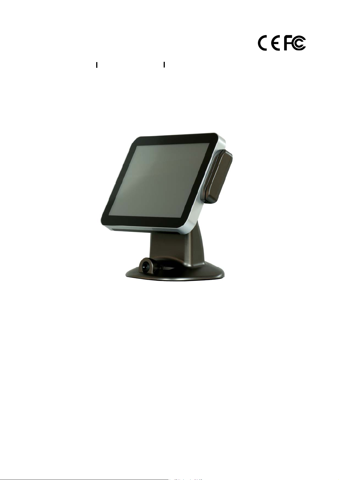
Fanless True Flat High Performance
COBRA15
USER MANUAL
15”All-in-One True Flat Touch Screen POS System
Version: 1.0
Date: Dec 26, 2012
Page 2

COBRA15
ii
About this Manual
Thank you for purchasing LONGSHINE COBRA15 All-in-One system. This terminal offers all the
enhanced features and is easy to connect to various optional devices for optimal performance.
This user manual describes how you can setup and connect your terminal.
Copyright
The information in this guide is subject to change without prior notice.© Copyright 2012
All rights reserved. This product and related documentation are protected by copyright and are
distributed under licenses restricting their use, copying, and distribution. No part of this
documentation may be reproduced in any form by any means without prior written
authorization of the manufacturer and its licensors, if any.
Version: 1.0
Page 3

COBRA15
iii
Federal Communications Commission (FCC)
Declaration of Conformity
This device complies with part 15 of the FCC Rules. Operation is subject to the following two
conditions:
1. This device may not cause harmful interference.
2. This device must accept any interference received, including interference that may cause
undesirable operation.
This equipment has been tested and found to comply within the limit of a Class A digital device,
pursuant to Part 15 of the FCC Rules. These limits are designed to provide reasonable protection
against harmful interference in a residential installation. This equipment generates, uses, and can
radiate radio frequency energy and, if not installed and used in accordance with the instructions,
may cause harmful interference to radio communications. However, there is no guarantee that
interference will not occur in a particular installation. If this equipment does cause harmful
interference to radio or television reception, which can be determined by turning the equipment
off and on, the user is encouraged to try to correct the interference by one or more of the
following measures:
Reorient or relocate the interference receiving antenna.
Increase the distance of separation between the equipment and interference receiver.
Connect the equipment to a power outlet on a circuit different from that to which the
interference receiver is connected.
Consult the dealer or an experienced radio/TV technician for help.
WARNING:
Use the included AC power cord so as not to interfere with radio and television reception.
If you use other cables, it may cause interference with radio and television reception.
WARNING:
TO PREVENT FIRE OR SHOCK HAZARD, DO NOT EXPOSE THIS APPLIANCE TO RAIN OR MOISTURE.
WARNING:
This is a equipment of Class A. This device could cause interferences in residential areas; in the case of interferences
it can be demand from the user to provide appropriate solutions for it.
WARNING:
The use of shielded cables for connection of the monitor to the graphics card is required to assure compliance with
FCC regulations. Changes or modifications to this unit not expressly approved by the party responsible for
compliance could void the user’s authority to operate this equipment.
RoHS
Version: 1.0
Page 4

COBRA15
iv
BEFORE YOU PROCEED
Read the safety notices and the User Manual carefully before using the product.
Keep the box and packaging in case the product needs to be shipped in the future.
Follow the product and warning label instructions.
For safety reasons, only qualified service personnel should open the terminal.
Any changes or modifications that do not follow the instructions in this manual will void
this product/s warranty.
! SAFETY PRECAUTIONS
In the interest of safety, please observe the following precautions:
Power Requirement:
This product is designed to operate on 110~240V AC 50/60Hz in Europe.
Never connect to any outlet or power supply having a different voltage or frequency.
! POWER SUPPLY SAFETY NOTICE
Disconnect this terminal from the AC outlet before cleaning. Use only a moistened cloth for
cleaning.
Check the voltage of the power source when connecting the equipment to the power
outlet. Make sure the voltage of the power outlet conforms within voltage range of the
terminal. Failure to comply may cause the electric shock or damage to the terminal. If you
are not sure of the electricity voltage that you are using, contact your local electricity
company.
To avoid electric shocks, disconnect the power cord from the electrical outlet before
relocating the system.
Do not overload electric power outlets to avoid fire or electric shocks.
Protect the power cord from being walked on or pinched particularly at plug.
If the equipment is not used for a long time, disconnect the equipment from the mains to
avoid damage.
Never allow liquid into ventilation openings. This could cause fire or electrical shock.
Version: 1.0
Page 5

COBRA15
v
! OPERATING INSTRUCTIONS
Keep the User Manual for future reference.
Follow the product label instructions.
Lay this terminal Upside down on a stable safe surface when installing. Heavy objects
placed on the product can cause damage or obstruct proper ventilation.
If one of the following situations arises, notify a qualified service technician immediately:
a. The power cord or plug is damaged.
b. The terminal has been dropped and damaged.
c. The terminal does not function according to the user manual.
d. The terminal has obvious signs of damage.
Do not place the unit where with high humidity and dust. They can cause extensive
damage. Avoid places where unit is likely to be exposed to oily fumes and vapors.
Places exposed to direct sunlight, or near heating appliances can attain extremely high
temperatures, which may deform the cabinet, or can become a prime cause of damage.
The operating ambient temperature range is 0 ゚ C to 35 ゚ C F ( 41 ゚ F - 95 ゚), and humidity of
10% - 90%. When using the unit on the system rack, be sure to keep this ambient
temperature inside the range.
Avoid shaky places or hot-springs areas where hydrogen sulfide and acidic ions are likely to
be generated.
When transporting this unit, make sure it is not likely to be subjected to impacts. They can
be a prime cause for damage.
Version: 1.0
Page 6

COBRA15
vi
CONTENTS
1. Introduction ................................................................................................................................ 7
1.1 How to use this manual.............................................................................................. 7
1.2 A Visual tour of COBRA15........................................................................................... 8
1.2a What comes with COBRA15 ............................................................................ 12
1.2b Dimensions of COBRA15 and its optional peripherals ..................................... 15
1.3 Features of COBRA15 ............................................................................................... 17
1.4 IO Interface .............................................................................................................. 18
2. Hardware setup ......................................................................................................................... 19
2.1 Pre-installation notice .............................................................................................. 19
2.2 General information ................................................................................................. 20
2.2.1 COM port power voltage ............................................................................... 20
2.2.2 Cash drawer power voltage ........................................................................... 23
2.3 Hardware assembly .................................................................................................. 26
2.3.1 HDD + SSD ..................................................................................................... 26
2.3.2 Memory ........................................................................................................ 28
2.3.3 CF card .......................................................................................................... 34
2.4 Optional peripherals installation .............................................................................. 37
2.4.1 MSR + RFID .................................................................................................... 37
2.4.2 2-Line VFD customer display .......................................................................... 39
2.4.3 i-Button reader .............................................................................................. 42
2.4.4 ADDIMAT reader ........................................................................................... 45
2.4.5 Second 7” 4-Line LCD display / 7” LCD display / 10” LCD display .................... 48
2.4.6 15” second display......................................................................................... 52
2.4.7 Fingerprint reader ......................................................................................... 54
2.4.8 2D image scanner .......................................................................................... 57
2.4.9 Internal speaker ............................................................................................ 60
2.4.10 WiFi ............................................................................................................. 63
3. Service manual .......................................................................................................................... 67
3.1 Touch panel ..................................................................................................................... 67
3.2 LCD panel ........................................................................................................................ 69
3.3 Motherboard ................................................................................................................... 72
4. Specification .............................................................................................................................. 75
Version: 1.0
Page 7

COBRA15
1. Introduction
Welcome
Thanks you for choosing LONGSHINE COBRA15. COBRA15 was designed to help enhancing your
business flexibility by offering a superior customer experience.
1.1 How to use this manual
This manual contains all the information needed for setting up a COBRA15. In addition, you can
also consult the manual for the instructions to assemble / to service the terminal and to install the
optional peripherals.
Introduction to COBRA15 and this user manual.
All necessary information for hardware setup.
Specifications of COBRA15 and configuration of the motherboard.
Information for troubleshooting COBRA15.
7 Version: 1.0
Page 8

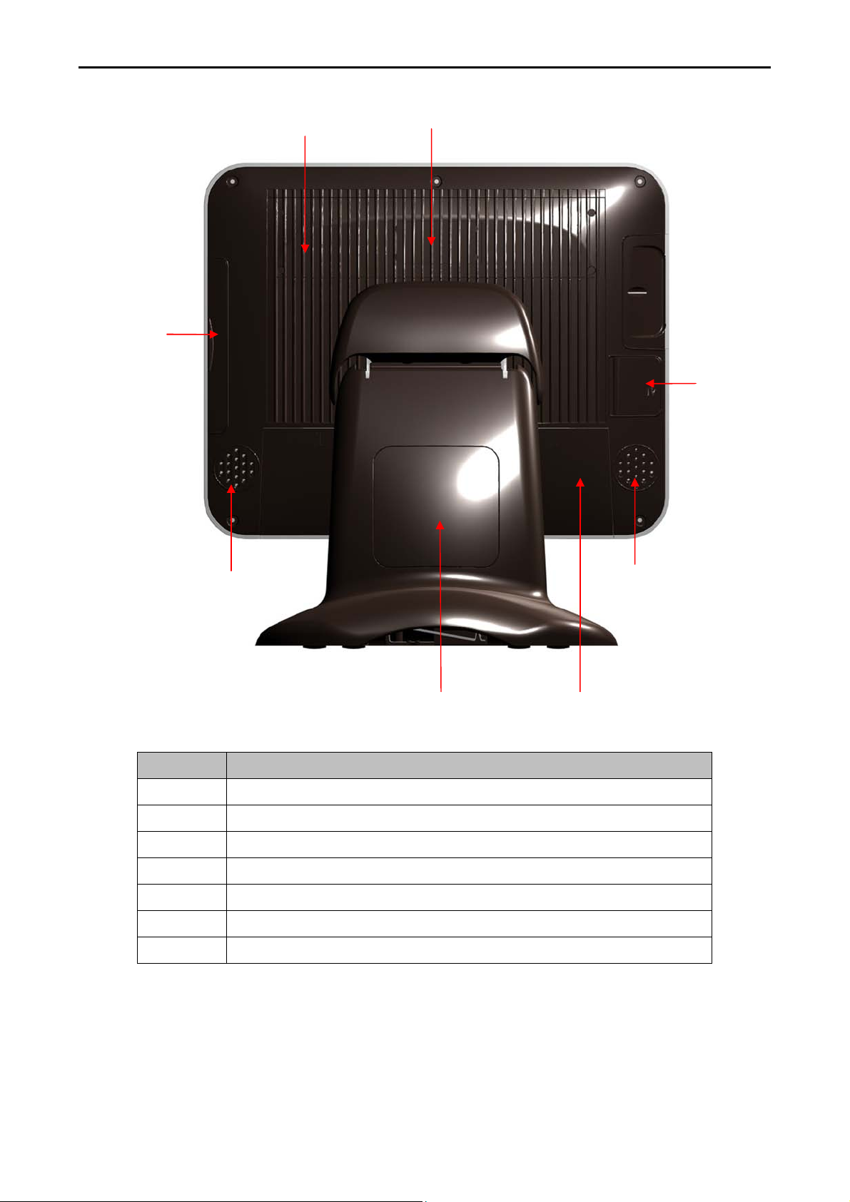
1.2 A Visual tour of COBRA15
Before you start, please take a few moments to become familiar with COBRA15 Terminal.
COBRA15
2
3
Elegant, Solid, Fashionable and Compact Design
1
4
Item No Description
1 Touch screen
2 Removable Hard drive Extraction slot
3 POWER LED
4 Base / Stand
5 Optional devices
5
8 Version: 1.0
Page 9
COBRA15
8
6
7
Item No Description
6 Function cover
9
11
10
9
12
7 Optional VFD ,7” and 10” Secondary Display cover
8 MSR & RFID cover
9 Speaker holes (speaker Optional)
10 Switch cover
11 VESA hole cover for 15”Secondary Display
12 Cable cover
9 Version: 1.0
Page 10
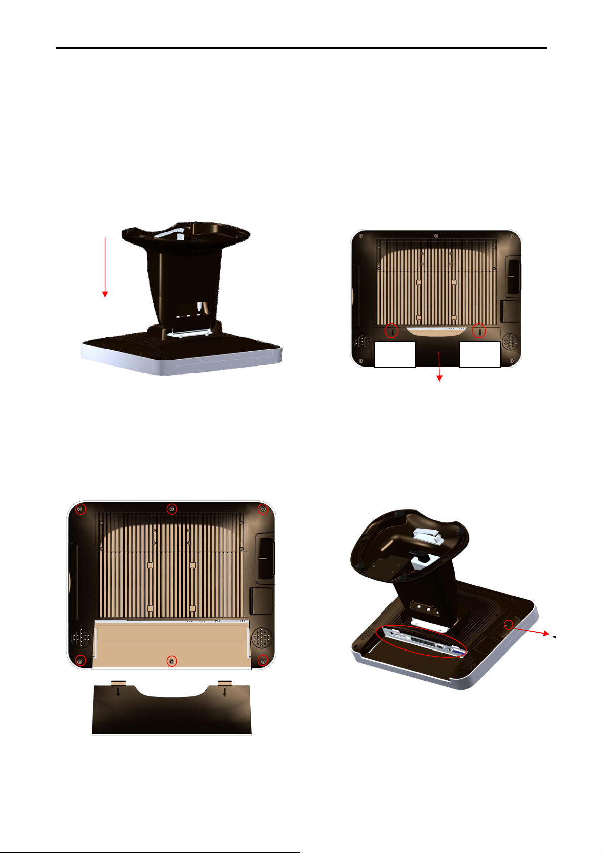
“Very Easy Maintenance”
Please follow the instructions to reach all inner components:
COBRA15
Step 1: Please position the terminal as shown below
on a working table with “soft protective pad”.
Step 3: Please remove the circled six
screws.
Step 2: Please remove cable cover by
sliding it downwards.
Push Push
Step 4: Please disconnect and remove all the
connected cables from IO interface and unscrew
the HDD screw.
10 Version: 1.0
Page 11
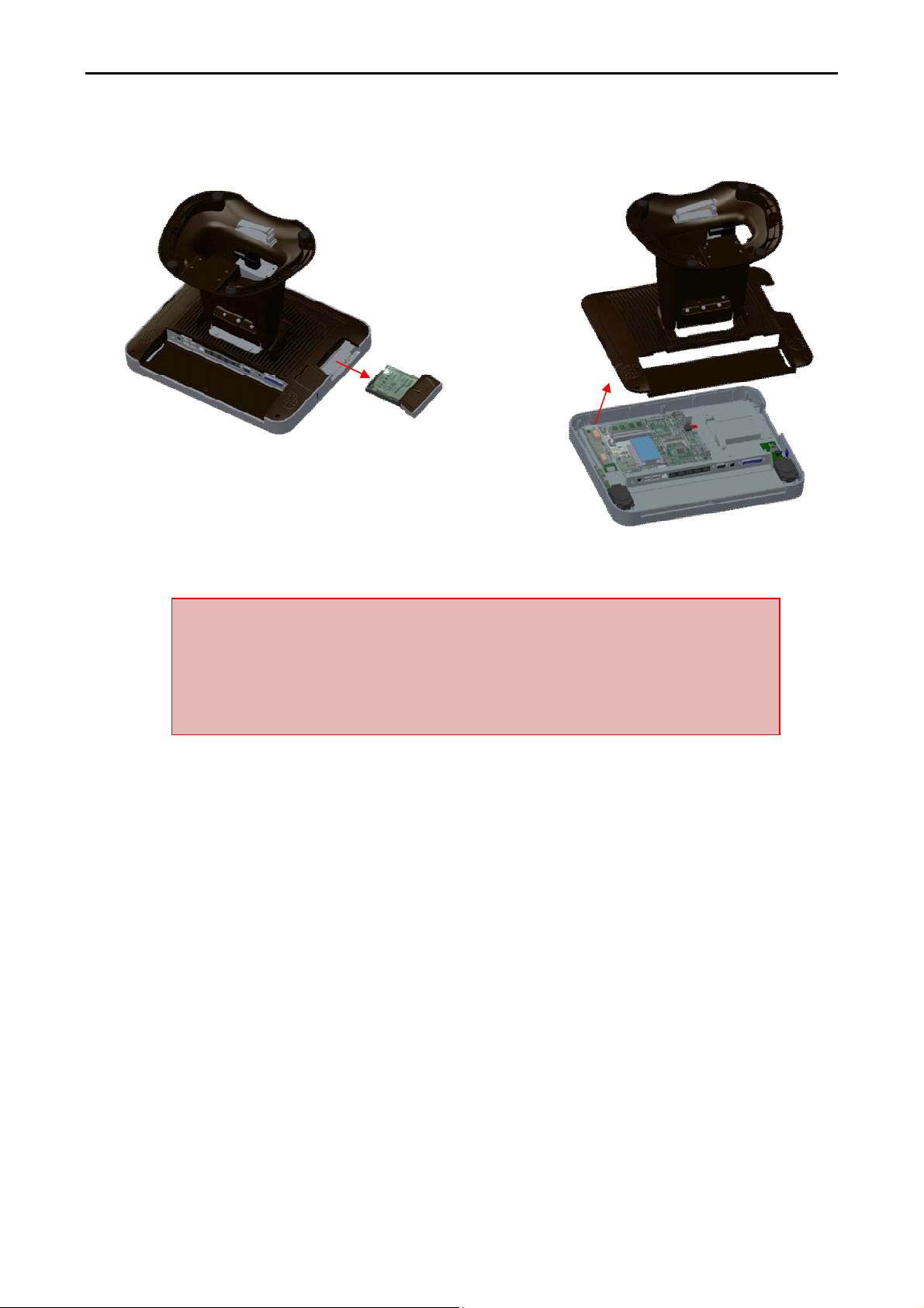
Step 5: Please unplug and remove the hard
disk.
COBRA15
Step 6: The back cover can now be removed.
Only authorized system engineers are advised to disassemble the device.
Please be aware that unauthorized modifications will void your warranty.
You are advised to contact your authorized supplier for technical support.
11 Version: 1.0
Page 12
COBRA15
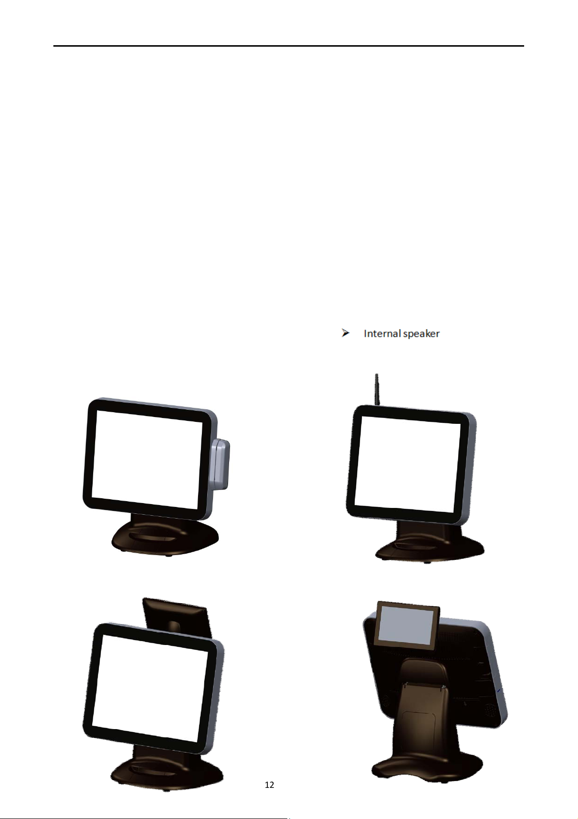
COBRA15 with MSR+RFID
COBRA15 with WiFi
1.2a What comes with COBRA15
Please check if your packaging contains below listed items before setting up your COBRA15. If any
of the items is missing or damaged, please contact your supplier immediately.
Main system with hidden power adapter in the stand.
CD for product User Manual, Touch Kits and Peripherals Drivers & Utilities.
M/B CD for user manual, drivers and utilities.
M/B CD for Windows XP drivers and utilities.
2 x 15cm RJ-45 to RS-232 converter cables and 2 x 40 cm RJ-45 to RS-232 converter cables.
AC power cord.
Optional Items:
MSR + RFID WiFi
Second 7”, 10”, 15” LCD display VFD customer display
2D Image scanner i-Button reader
ADDIMAT reader
Fingerprint reader
COBRA15 with second 7”,10” LCD monitor and 7” customer display
12 Version: 1.0
Page 13
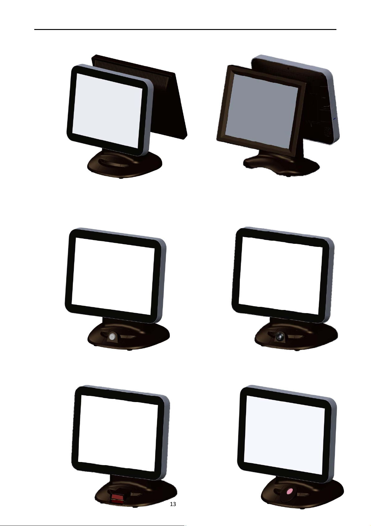
COBRA15
COBRA15 with
i-
Button
reader
COBRA15 with A
DDIMAT reader
COBRA15 with 2D Image
s
can
ner COBRA15 with
Fingerprint
reader
COBRA15 with second 15” LCD monitor
13 Version: 1.0
Page 14
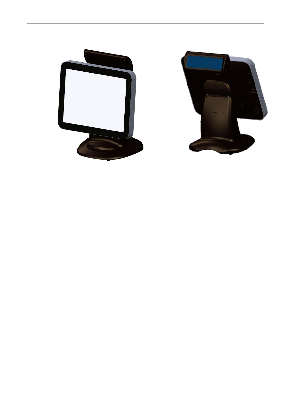
COBRA15 with VFD customer display
COBRA15
14 Version: 1.0
Page 15
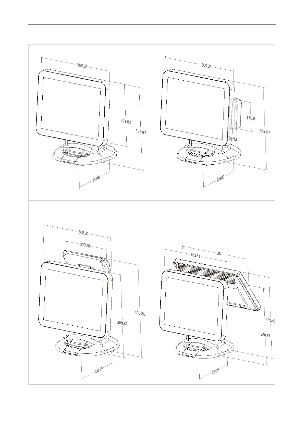
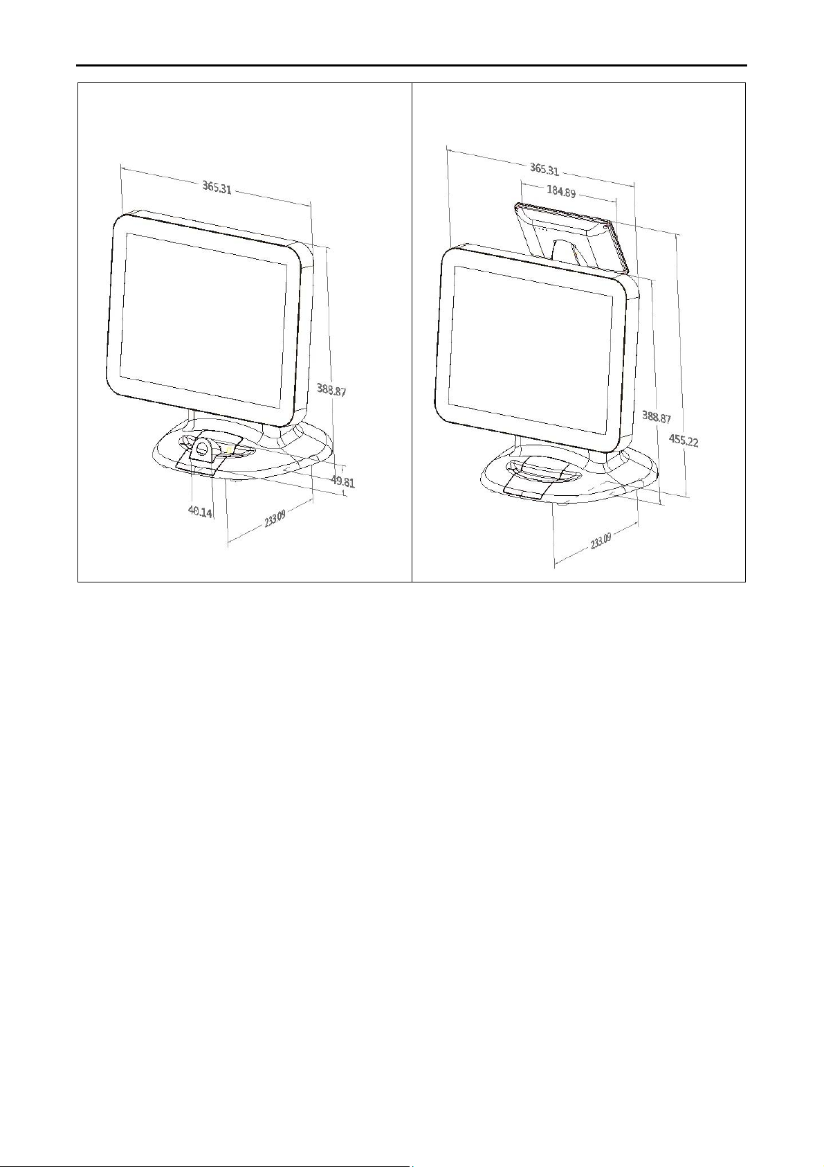
1.2b Dimensions of COBRA15 and its optional peripherals
COBRA15
15” COBRA15 dimensions:
15” COBRA15 with MSR+RFID integrated:
15” COBRA15 with VFD customer display
integrated:
15” COBRA15 with 15” second LCD monitor
integrated:
15 Version: 1.0
Page 16
15” COBRA15 with ADDIMAT/i-Button/
COBRA15
15” COBRA15 with second 10” LCD monitor
Fingerprint/ 2D image scanner integrated:
and 7” 4-Line customer display integrated:
16 Version: 1.0
Page 17

COBRA15
1.3 Features of COBRA15
Low power consumption LV (Low Voltage) design of the device is embedded
with a unique chipset and CPU renders power saving
function.
Saving cost of ownership Modular design provides the owner with the
following benefits:
(a) cost effectiveness,
(b) customization flexibility, and
(c) Easy maintenance.
Dust/water proof COBRA15 features a highly durable, rigorously tested
design that is reliable and dependable in rugged
environments.
Environment protection
Environmental friendly, RoHS compliant product.
High Stability COBRA15 has a longer overall system MTBF to
provide a higher stability during operation.
17 Version: 1.0
Page 18
COBRA15
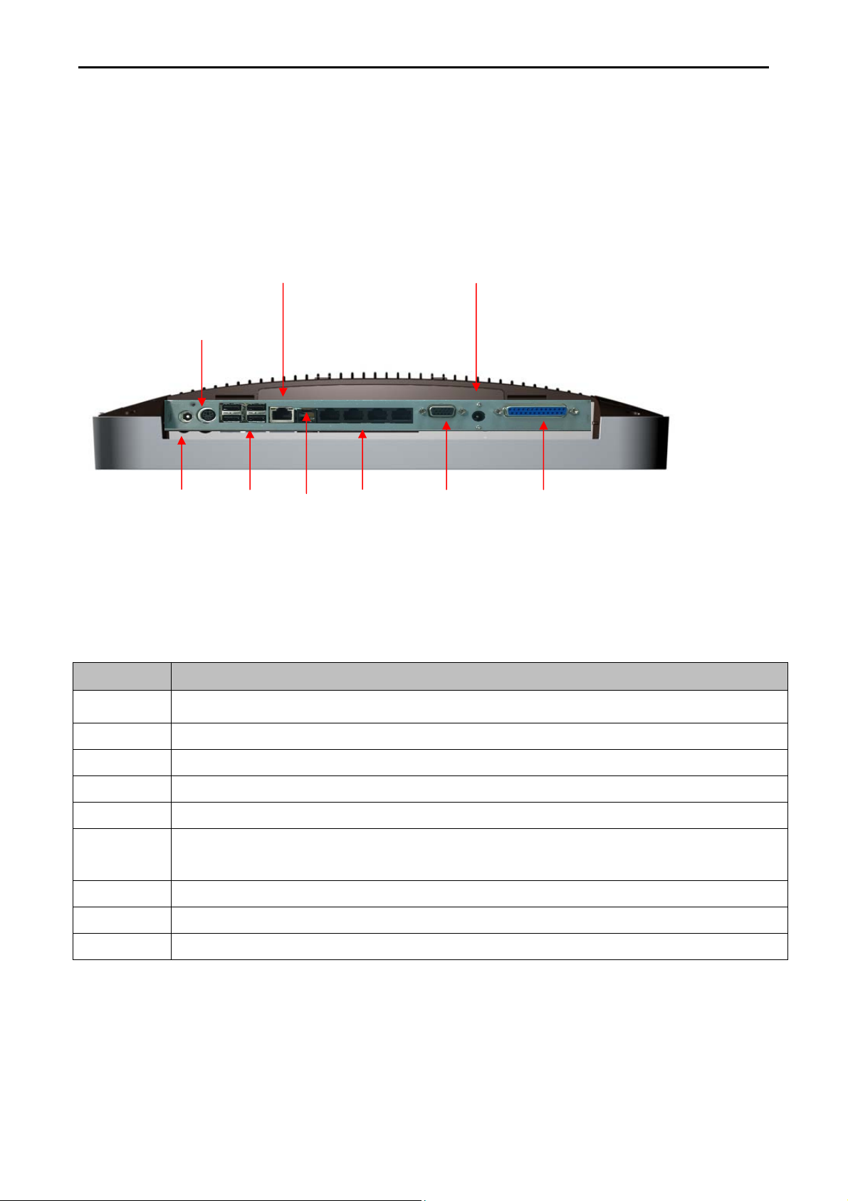
1.4 IO Interface
IO interface is located at the bottom of the display. To clearly see IO interface you must remove
the cable cover.
B
Chart of the connector panel:
A C
D
E F
G
H
I
Item No Description
A Power DC-IN 12V
B PS/2 Keyboard / Mice Output
C 4 USB 2.0 Port
D Gigabit - LAN Port
E RJ-12 Cash drawer port
F
G VGA OUT
H Power DC-OUT 12V (36W Max)
I LPT Port (default) or one USB Port (optional)
COM1 –COM4 Serial Ports (the serial ports for BIOS Setup 0/ +5V/ +12V-1A MAX
power output ,RJ-45 on PIN5 and D-SUB9 on PIN9)
18 Version: 1.0
Page 19

COBRA15
2. Hardware setup
Getting Started
This section describes how to install or to replace accessories and component on your COBRA15.
2.1 Pre-installation notice
Before you start installing COBRA15 terminal, please read the following notices carefully.
1. COBRA15 terminal does not support PCI slot.
2. Do not plug in or unplug any interior devices, such as memory module or any function card,
when the system power is still on.
3. For installation and compatibility, DDR3 RAM Module provided by the manufacturer is strongly
recommended.
4. The USB device connector is Hot Swap. Do not plug in or unplug any connectors other than
USB devices when the power is still on.
5. Do not insert or remove any devices or components from COBRA15 while the power is still on.
6. Please make sure that flat touch screen will be well protected by soft pad on working table.
When positioning COBRA15 with display facing downwards.
19 Version: 1.0
Page 20
2.2 General information
2.2.1 COM port power voltage
COBRA15
Warning!!Please check with your device provider for correct power voltage
for each accessory. Incorrect power voltage setting can cause damage on
device and terminal.
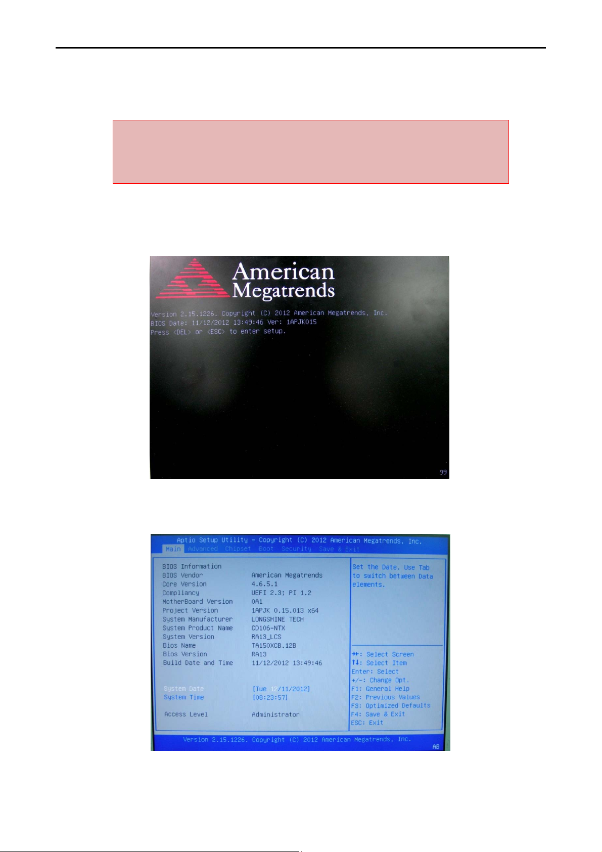
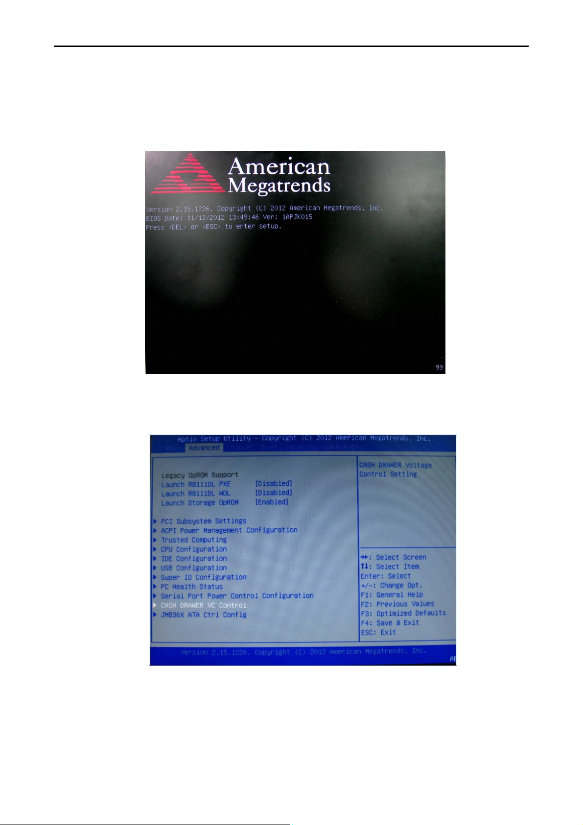
Step 1: Please switch on COBRA15; BIOS message appears on the screen and the memory count
begins. After the memory test, the message “Press DEL to run setup” will appear on the screen.
Please press “DEL” on the keyboard to enter into BIOS.
20 Version: 1.0
Page 21
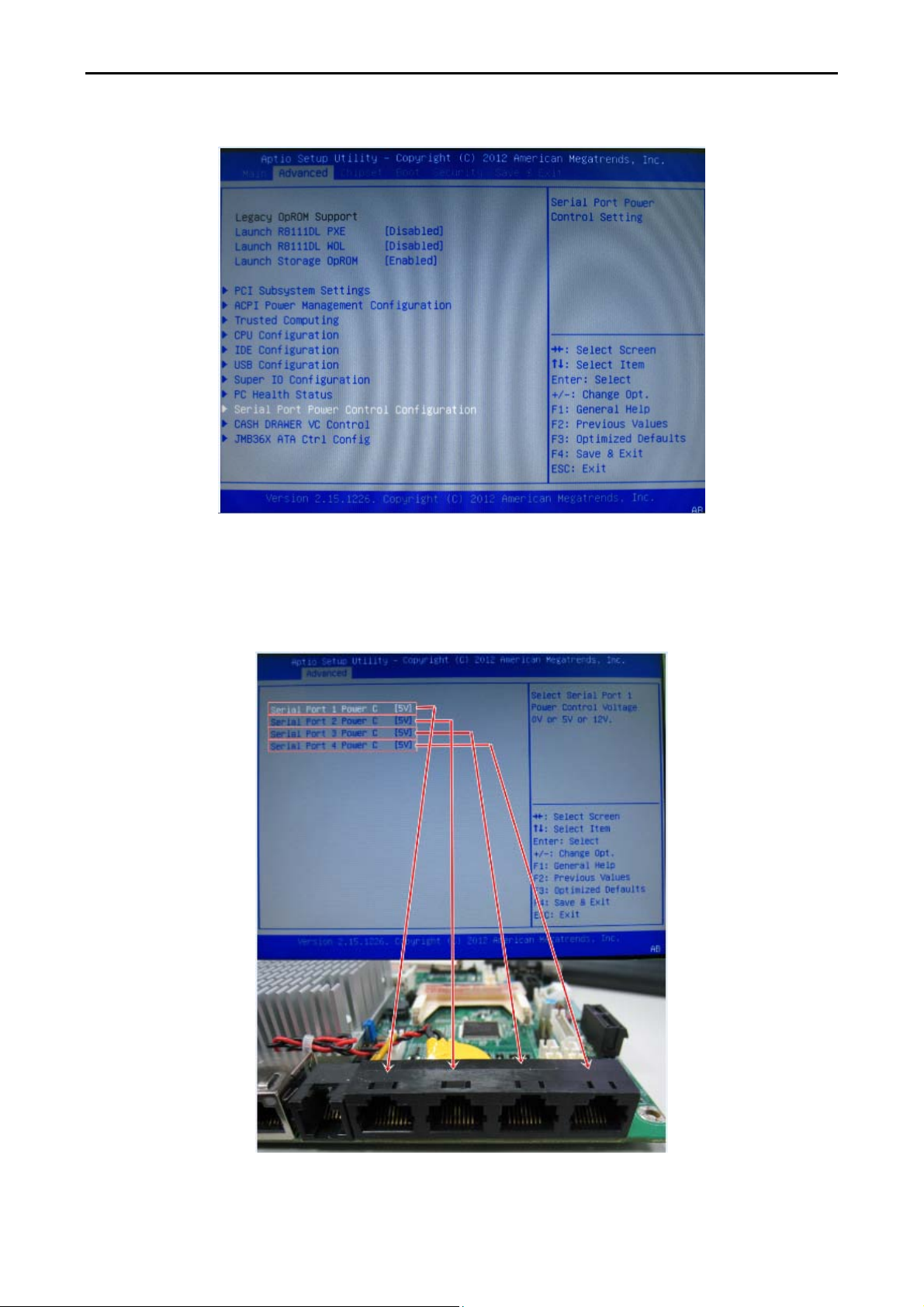
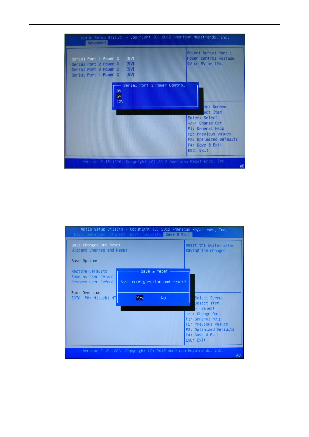
Step 2: Select “Serial Port Power Control Configuration” from the Tab “Advanced”.
COBRA15
Step 3: Please check with your device provider for correct voltage on accessory and select correct
power voltage for the accessory.
Please NOTE that the default voltage is 0V.
21 Version: 1.0
Page 22
COBRA15
Step 4: Please press “ESC” on the keyboard to go back to main screen of BIOS and select
”Save Change and Reset” from the Tab”Save & Exit”. Please select “Yes” to exit BIOS.
22 Version: 1.0
Page 23
COBRA15
2.2.2 Cash drawer power voltage
Step 1: Please switch on COBRA15; BIOS message appears on the screen and the memory count
begins. After the memory test, the message “Press DEL to run setup” will appear on the screen.
Step 2: Please select “Cash drawer VC Control” from the Tab “Advanced”.
23 Version: 1.0
Page 24

COBRA15
Step 3: Please check with your Cash Drawer provider for the correct voltage on Cash Drawer and
select correct power voltage for Cash Drawer.
Please NOTE that the default voltage for Cash drawer port is +24V.
24 Version: 1.0
Page 25

COBRA15
Step 4: Please press “ESC” on the keyboard to go back to main screen of BIOS and select “Save
Change and Reset” from the Tab ”Save & Exit”. Please select “Yes” to exit BIOS.
25 Version: 1.0
Page 26

COBRA15
in place
.
2.3 Hardware assembly
Please make sure that the system power is turned off and the power supply is disconnected when
making any hardware changes to COBRA15.
2.3.1 HDD + SSD
Step 1: Please remove the HDD
screw.
Step 3: Dismounting HDD from the tray
requires two screws to be removed.
Step 2: Please pull out and retrieve
HDD or SSD.
Step 4: Then remove HDD or SSD
from the tray.
Step 5: Please insert new HDD or SSD
into the tray.
Step 6: Please tighten left and right
screws indicated below to fix HDD or SSD
26 Version: 1.0
Page 27

Step 7: Please push in HDD or SSD into the terminal
COBRA15
Step 8: Please tighten the circled
where indicated below.
screw to complete the installation.
27 Version: 1.0
Page 28

2.3.2 Memory
Step 1: Please remove four screws indicated
Step 2: Please see below where RAM
COBRA15
below to expose memory module.
NOTE:
The memory is located in the upper portion of MB.(When replacing the memory module,
please make sure that the memory is properly positioned and snapped into place)!
DDR3-1
module can be reached for replacement.
DDR3-0
28 Version: 1.0
Page 29

COBRA15
Please follow the instructions below to change memory on COBRA15.
1. Make sure that the terminal and all other peripherals which are connected to the terminal
have been powered down and unplugged.
2. Disconnect all power cords and cables.
3. Locate the SO-DIMM socket on the system board.
NOTE the key on the socket. The key ensures the module can be plugged into the socket in only
one direction.
5. Grasping the module by its edges, align the module into the socket at an approximately 30
degrees on the socket. The contact fingers on the edge of the module will almost completely
disappear inside the socket.
29 Version: 1.0
Page 30

COBRA15
7. Push down the module until the clips at each end of the socket lock into position. You will hear
a distinctive click, indicating the module is correctly locked into position.
Clip
Clip
30 Version: 1.0
Page 31

2.3.3 Mini-PCI-E m-SATA SSD
COBRA15
Step 1: Please position the terminal as shown below
on a working table with “soft protective pad”.
Step 3: Please remove the circled six
screws.
Step 2: Please remove cable cover by
sliding it downwards.
Push Push
Step 4: Please disconnect and remove all the
connected cables from IO interface and unscrew
the HDD screw.
31 Version: 1.0
Page 32

hard disk.
COBRA15
Step 6: The back cover can now be removed. Step 5: Please unplug and remove the
Step 7: Mini PCI-E Connecter can then be found where circled.
32 Version: 1.0
Page 33

Step 8: Connect Pin Head and push header directly into Mini PCI-E Connecter.
COBRA15
Step 9: Please reverse step 1~6 to assemble the terminal.
Only authorized system engineers are advised to disassemble the device.
Please be aware that unauthorized modifications will void your warranty.
You are advised to contact your authorized supplier for technical support.
33 Version: 1.0
Page 34

2.3.3 CF card
COBRA15
Step 1: Please position the terminal as shown below
on a working table with “soft protective pad”.
Step 3: Please remove the circled six
screws.
Step 2: Please remove cable cover by
sliding it downwards.
Push Push
Step 4: Please disconnect and remove all the
connected cables from IO interface and unscrew
the HDD screw.
34 Version: 1.0
Page 35

Step 5: Please unplug and remove the hard
disk.
COBRA15
Step 6: The back cover can now be removed.
Step 7: CF card slot can then be found where circled.
35 Version: 1.0
Page 36

Step 8: Please push CF card directly in place.
COBRA15
Step 9: Please reverse step 1~6 to assemble the terminal.
Only authorized system engineers are advised to disassemble the device.
Please be aware that unauthorized modifications will void your warranty.
You are advised to contact your authorized supplier for technical support.
36 Version: 1.0
Page 37

COBRA15
2.4 Optional peripherals installation
2.4.1 MSR + RFID
Step 1: Please position the terminal as shown below on a working table with “soft protective pad”.
Step 2: Please remove MSR cover to find USB connecter.
Step 3: Please refer to the chart below for P/N assignment of USB. Terminal does not support P/S2
interface.
MSR RFID
Pin No function Pin No function
9 GND 10 5V
7 GND 8 Data -
4 Data + 6 Data +
3 Data - 4 GND
1 5V 2 GND
1
2
37 Version: 1.0
Page 38

COBRA15
Step 4: Please tightly plug in the connector into USB pin header in correct orientation.
Step 5: Please sort the cable inside MSR housing and lock the two screws indicated below.
Step 6: Integration completed.
38 Version: 1.0
Page 39

2.4.2 2-Line VFD customer display
Step 1: Please remove four screws indicated below.
Step 2: Please remove four screws indicated below to release the display cover.
COBRA15
Step 3: Please check interface of VFD customer
display.
Step 4: Please fix VFD to function cover as
shown below.
Cable should be led through the alignment hole.
39 Version: 1.0
Page 40

COBRA15
Step 5: Please screw four screws indicated below to fix VFD customer display on to function cover.
Step 6: Please refer to the follow drawing and adjust the jumper (JP7) on the motherboard to
provide +5V/ +12V power for VFD customer display.
NOTE: The device can choose either RS232 (as default) or USB (optional). Please contact your
device provider for correct interface.
40 Version: 1.0
Page 41

COBRA15
Step 7: Please screw four screws indicated below to install VFD customer display to COBRA15.
Step 8: Integration completed.
Only authorized system engineers are advised to disassemble the device.
Please be aware that unauthorized modifications will void your warranty.
You are advised to contact your authorized supplier for technical support.
41 Version: 1.0
Page 42

COBRA15
2.4.3 i-Button reader
Step 1: Please position the terminal as shown below on a working table with “soft protective pad”.
Step 2: Please remove four screws indicated below.
Step 3: Please remove the peripheral cover
as shown below.
Step 4: Please check the interface of i-Button before integration.
NOTE: The device can choose either RJ-45 (RS232) as default or USB (optional). Please contact
with your device provider for correct interface.
42 Version: 1.0
Page 43

Step 5: Please position the terminal as shown
COBRA15
Step 6: Please follow arrows in below
below on soft protective pad and screw four screws
diagram to sort the cable of i-Button.
indicated in below diagram.
Step 7: Please remove cable cover by sliding it downwards.
43 Version: 1.0
Page 44

COBRA15
Step 8: If interface of i-Button is RJ45(RS232), please connect cable to COM1~COM4 which is RJ-45
type. If interface of i-Button is USB, please connect cable directly to USB port.
Step 9: Please assemble the cover back.
Step 10: Integration completed.
Step 11: If interface of i-Button is COM port, please refer to 2.2.1 to change the power of COM
port from 0 to +5V.
44 Version: 1.0
Page 45

COBRA15
2.4.4 ADDIMAT reader
Step 1: Please position the terminal as shown below on a working table with “soft protective pad”.
Step 2: Please remove four screws indicated below.
Step 4: Please see below diagram of ADDIMAT reader.
Step 3: Please remove the peripheral cover
as shown below.
Step 5: Please properly fit ADDIMAT reader
to where circled.
45 Version: 1.0
Page 46

Step 6: Please position the terminal as shown
COBRA15
Step 7: Please follow arrows in below diagram
below on soft protective pad and screw four screws
to sort cable of ADDIMAT reader.
indicated in below diagram.
Step 8: Please remove cable cover by sliding it downwards.
46 Version: 1.0
Page 47

COBRA15
Step 9: Please use RJ45 to D-SUB9 converter cable to connect with original cable from ADDIMAT
reader and then connect converter cable to COM1~4.
Step 10: Please fix the cable cover back to the terminal.
Step 10: Integration completed.
Step 11: If interface of ADDIMAT reader is COM, please refer to 2.2.1 to change the power of COM
port from 0 to 5V.
47 Version: 1.0
Page 48

2.4.5 Second 7” 4-Line LCD display / 7” LCD display / 10” LCD display
Step 1: Please remove screws indicated below.
Step 2: Please remove four screws indicated below to release the display cover.
COBRA15
Step 3: Please fix second display to function cover and screw four screws as shown below.
Cable should be led through the alignment hole.
48 Version: 1.0
Page 49

COBRA15
Step 4: Please refer to the following drawings and connect the connectors (USB, VGA or RS232) of
7”, 10” second display to the correct connector on M/B.
49 Version: 1.0
Page 50

COBRA15
50 Version: 1.0
Page 51

Step 5: Please screw four screws indicated below to install LCD display to COBRA15.
COBRA15
Step 6: Integration completed.
51 Version: 1.0
Page 52

COBRA15
2.4.6 15” second display
Step 1: Please position the terminal as shown below on a working table with “soft protective pad”.
Please remove cable cover by sliding it downwards.
Step 2: Please push out VESA hole cover from inside the stand.
52 Version: 1.0
Page 53

Step 3: Please use four screws to fix VESA arm to the
COBRA15
Step 4: Please sort and hide the cable
terminal as shown below.
NOTE:
VESA arm of 2nd 15” display was designed for
standard 75cm VESA hole.
through VESA arm and connect it to the
terminal as instructed below.
Step 5: Please connect the cables to terminal 12V
DC OUT and VGA.
Step 6: Please close cable cover back
in place.
Step 7: Please change power adapter from 60W to 80W.
NOTE: With 15” 2nd second LCD display, you must install 80W power adapter for COBRA15 instead
of 60W power adapter.
53 Version: 1.0
Page 54

COBRA15
2.4.7 Fingerprint reader
Step 1: Please position the terminal as shown below on a working table with”soft protective pad”.
Step 2: Please remove four screws indicated below.
Step 3: Please remove the peripheral cover
as shown below.
Step 4: Please properly fit Fingerprint reader to where circled.
.
54 Version: 1.0
Page 55

COBRA15
Step 5: Please position the terminal as shown below on soft protective pad and screw four screws
indicated in below diagram.
NOTE: Cable should go through the hole.
Step 6: Please follow arrows in below diagram to sort cable of Fingerprint reader.
Step 7: Please remove cable cover by sliding it downwards.
55 Version: 1.0
Page 56

Step 8: For USB interface, please connect USB cable directly to USB port.
COBRA15
Step 9: Please fix the cable cover back to the terminal.
Step 10: Integration completed.
56 Version: 1.0
Page 57

COBRA15
2.4.8 2D image scanner
Step 1: Please position the terminal as shown below on a working table with”soft protective pad”.
Step 2: Please remove four screws indicated below.
Step 3: Please remove the peripheral cover
as shown below.
Step 4: Please properly fit 2D image scanner to where circled.
.
57 Version: 1.0
Page 58

COBRA15
Step 5: Please position the terminal as shown below on soft protective pad and screw four screws
indicated in below diagram.
NOTE: Cable should be go through the hole.
Step 6: Please follow arrows in below diagram to sort cable of 2D image scanner.
Step 7: Please remove cable cover by sliding it downwards.
58 Version: 1.0
Page 59

COBRA15
Step 8: For USB interface, please connect USB cable directly to USB port on the terminal.
Step 9: Please fix the cable cover back to the terminal.
Step 10: Integration completed.
59 Version: 1.0
Page 60

2.4.9 Internal speaker
COBRA15
Step 1: Please position the terminal as shown below
on a working table with “soft protective pad”.
Step 3: Please remove the circled six
screws.
Step 2: Please remove cable cover by
sliding it downwards.
Push Push
Step 4: Please disconnect and remove all the
connected cables from IO interface and unscrew
the HDD screw.
60 Version: 1.0
Page 61

hard disk.
Step 5: Please unplug and remove the
COBRA15
Step 6: The back cover can now be removed.
Step 7: Internal left and right speaker can be integrated to COBRA15 with circled six screws in
below diagram.
61 Version: 1.0
Page 62

Step 8: Please connect speaker cables directly to M/B Audio ports.
COBRA15
Step 9: Reverse step 1-6 to assemble the terminal.
62 Version: 1.0
Page 63

2.4.10 WiFi
COBRA15
Step 1: Please position the terminal as shown below
on a working table with “soft protective pad”.
Step 3: Please remove the circled six
screws.
Step 2: Please remove cable cover by
sliding it downwards.
Push Push
Step 4: Please disconnect and remove all the
connected cables from IO interface and unscrew
the HDD screw.
63 Version: 1.0
Page 64

Step 5: Please unplug and remove the
hard disk.
COBRA15
Step 6: The back cover can now be removed.
Step 7: Please align WiFi mini PCI-E card into mini PCI-E slot at an approximately 30 degrees on the
slot and properly push it into the slot.
64 Version: 1.0
Page 65

COBRA15
Step 8: There are two antenna wires on WiFi module. Please fix internal antenna inside the front
bezel shown below on the left hand side.
Please nicely sort external antenna cable where shown below on the right top corner to
connected to external antenna.
ANT1: External antenna
ANT2: Internal antenna
Internal antenna External antenna connecter
65 Version: 1.0
Page 66

External antenna
Step 9: Please reverse step 1-6 to assemble the machine.
COBRA15
66 Version: 1.0
Page 67

3. Service manual
3.1 Touch panel
COBRA15
Step 1: Please position the terminal as shown below
on a working table with “soft protective pad”.
Step 3: Please remove the circled six
screws.
Step 2: Please remove cable cover by
sliding it downwards.
Push Push
Step 4: Please disconnect and remove all the
connected cables from IO interface and unscrew
the HDD screw.
67 Version: 1.0
Page 68

Step 5: Please unplug and remove the hard
disk.
COBRA15
Step 6: The back cover can now be removed.
Step 7: Please remove eight screws indicated below to separate touch panel from COBRA15.
Step 8: After touch panel is replaced, please reverse the step 1-7 to assemble the machine.
68 Version: 1.0
Page 69

3.2 LCD panel
COBRA15
Step 1: Please position the terminal as shown below
on a working table with “soft protective pad”.
Step 3: Please remove the circled six
screws.
Step 2: Please remove cable cover by
sliding it downwards.
Push Push
Step 4: Please disconnect and remove all the
connected cables from IO interface and unscrew
the HDD screw.
69 Version: 1.0
Page 70

Step 5: Please unplug and remove the hard
disk.
COBRA15
Step 6: The back cover can now be removed.
Step 7: Remove 4 screws for holder and 4 screws for touch panel. Then you can separate touch
pane from COBRA15.
70 Version: 1.0
Page 71

COBRA15
Step 8: Please loosen four screws and disconnect the inverter and touch connectors to remove
LCD.
Step 9: Please disconnect LVDS cable to separate LCD from M/B.
Step 10: Please reverse step 1-9 to assemble the machine.
71 Version: 1.0
Page 72

3.3 Motherboard
COBRA15
Step 1: Please position the terminal as shown below
on a working table with “soft protective pad”.
Step 3: Please remove the circled six
screws.
Step 2: Please remove cable cover by
sliding it downwards.
Push Push
Step 4: Please disconnect and remove all the
connected cables from IO interface and unscrew
the HDD screw.
72 Version: 1.0
Page 73

Step 5: Please unplug and remove the hard
disk.
COBRA15
Step 6: The back cover can now be removed.
Step 7: Please disconnect all indicated connectors on M/B
73 Version: 1.0
Page 74

Step 8: Please remove four screws from M/B to separate and replace motherboard from
COBRA15.
COBRA15
Step 9: Please reverse step 1-8 to assemble the machine.
74 Version: 1.0
Page 75

4. Specification
Technical Information
Technical Requirements
CPU Intel N2800 1.86 GHz, 1M Cache, BGA (6.55W)
Core Logic Intel NM10 Family Express Chipset
BIOS AMI
VGA Controller VGA Controller Intel GMA 3650 graphics will run at 640 MHz
COBRA15
COBRA15 System Specifications
-Two 204-pin DDR3 SDRAM Small Outline Dual Inline Memory Module
(SO-DIMM) sockets.
Memory
Audio
Display
Storage
Connectivity Requirements
Wireless Optional 3rd Party b/g/n
Ethernet
-C11Support for DDR3 800 MHz and DDR3 1066 MHz SO-DIMM.
-Support for up to 4 GB of system memory on a single SO-DIMM (or two 2 GB
SO-DIMMs)
- 2 GB x1 , 2G x2 , 4G x1
HD audio support; MS-Sound compatible
2W Amplifier ( option)
Supports LVDS displays up to 1440 x 900 (dual-channel ,60 Hz; 24 bpps)
LCD : 15" 1024 X 768
Touch Screen : 15" 5-wired Resistive true zero bezel touch screen.
2.5" SATAII 160GB/320GB/500GB
Optional 2.5" SATAII SSD
Optional Mini-PCI-E m-SATA SSD
CF card
Realtek RTL8111DL
10/100/1000 Mb/s (Gigabit) Ethernet Subsystem.
External I/O Requirements
USB 2.0 4 +1
RS232
RJ11 1 support 12V/24V output, with BIOS control.
VGA 1
PS2 1 ( K/M COMB)
RJ45 1
75 Version: 1.0
4 (RJ-45 type) ,support +5v/+12v output, with BIOS control
COM1 with BIOS Adjustable to RS422/RS485 (option)
Page 76

PRINTER 1
DC in 1 2 PIN DC JACK.
Option Requirements
MSR+RFID USB I/F
2x 20 VFD Customer Display RS232 I/F, USB(optional)
i-Button RS232 I/F,USB(optional)
CF Storage CF card
Internal Speaker 2W Speaker
ADDIMAT-AG RS232 I/F, USB(optional)
4-Line 7” customer Display RS232 I/F ,USB(optional)
Second Display 7" LCD VGA I/F,USB(optional)
Second Display 15" LCD VGA I/F
Second Display 10" LCD VGA I/F, USB(optional)
fingerprint USB I/F
COBRA15
2D Scanner USB I/F
Power Requirements
Direct DC input 12V DC
AC Adaptor 12V, 60W, 100-240v, 50/60Hz AC or 12V, 80W, 100-240v, 50/60Hz AC
Other Requirements
OS POSReady 2009, win XP , POSReady 7, Win 7. Linux
Indicator Power on LED
Button Power on
APP OSD ( menu FN , LCD backlight adjust )
Regulation Requirement
Green Product RoHS, REACH
EMC CE CLASS A , FCC Part 15 Subpart B,CLASS A
76 Version: 1.0
 Loading...