


cod. 1-5302-351
WORKSHOP MANUAL
FOCS Engine Series


- 3 -
Manuale officina FOCS_cod. 1.5302.350_7° ed_ rev. 06
PREFACE
-Every attempt has been made to present within this service manual, accurate and up to date technical
information.
However, development on the LOMBARDINI series is continuous.
Therefore, the information within this manual is subject to change without notice and without obligation.
-The information contained within this service manual is the sole property of LOMBARDINI.
As such, no reproduction or replication in whole or part is allowed without the express written permission of
LOMBARDINI.
Information presented within this manual assumes the following:
1- The person or people performing service work on LOMBARDINI series engines is properly trained and
equipped to safely and professionally perform the subject operation;
2- The person or people performing service work on LOMBARDINI series engines possesses adequate hand and
LOMBARDINI special tools to safely and professionally perform the subject service operation;
3- The person or people performing service work on LOMBARDINI series engines has read the pertinent
information regarding the subject service operations and fully understands the operation at hand.
- This manual was written by the manufacturer to provide technical and operating information to authorised
LOMBARDINI after-sales service centres to carry out assembly, disassembly, overhauling, replacement and
tuning operations.
- As well as employing good operating techniques and observing the right timing for operations, operators must read
the information very carefully and comply with it scrupulously.
- Time spent reading this information will help to prevent health and safety risks and financial damage.
Written information is accompanied by illustrations in order to facilitate your understanding of every step of the
operating phases.
FOCS Engine Series

- 4 -
FOCS Workshop Manual_cod. 1.5302.351_7° ed_ rev. 06
-
CUSE/ATLO
7° 04-906 15.03.20081-5302-351 50563
Drafting
body
Document
code
Edition Issue date
Review
date
Model
N°
Revision
REGISTRATION OF MODIFICATIONS TO THE DOCUMENT
Any modifications to this document must be registered by the drafting body, by completing the following table.
Endorsed

- 5 -
FOCS Workshop Manual_cod. 1.5302.351_7° ed_ rev. 06
-
CHAPTER INDEX
1GENERAL REMARKS AND SAFETY INFORMATION................................................................ Pag. 9 - 11
GENERAL SAFETY DURING OPERATING PHASES .................................................................................................... 11
GENERAL SERVICE MANUAL NOTES ............................................................................................................................ 9
GLOSSARY AND TERMINOLOGY ................................................................................................................................... 9
SAFETY AND ENVIRONMENTAL IMPACT .................................................................................................................... 11
SAFETY AND WARNING DECALS ................................................................................................................................. 10
SAFETY REGULATIONS ........................................................................................................................................... 10-11
WARRANTY CERTIFICATE ............................................................................................................................................... 9
2TECHNICAL INFORMATION.................................................................................................................. 12-23
MANUFACTURER AND ENGINE IDENTIFICATION ................................................................................................ 14-15
OVERALL DIMENSION .............................................................................................................................................. 21-23
PERFORMANCE DIAGRAMS .................................................................................................................................... 18-20
TECHINICAL SPECIFICATIONS ............................................................................................................................... 16-17
TROUBLE SHOOTING ............................................................................................................................................... 12-13
3MAINTENANCE - RECOMMENDED OIL TYPE - REFILLING.............................................................. 24-27
ACEA Regualtions - ACEA Sequences ............................................................................................................................ 25
API / MIL Sequence .......................................................................................................................................................... 25
COOLANT .........................................................................................................................................................................27
FUEL SPECIFICATIONS .................................................................................................................................................. 27
International specifications............................................................................................................................................... 25
LUBRICANT ......................................................................................................................................................................25
PRESCRIBED LUBRICANT ............................................................................................................................................. 26
ROUTINE ENGINE MAINTENANCE ............................................................................................................................... 24
SAE Classification ........................................................................................................................................................... 25
4DISASSEMBLY / REASSEMBLY........................................................................................................... 28-65
Air filter support ................................................................................................................................................................ 30
Air restriction switch ......................................................................................................................................................... 29
Alternator/Cooling fan belt drive ....................................................................................................................................... 33
Big end bearing ................................................................................................................................................................. 58
Camshaft journals and housings - Dimensions ...............................................................................................................47
Camshaft lobe measurement ...........................................................................................................................................47
Camshaft timing - Belt Reassembly ................................................................................................................................ 37
Camshaft timing - Belt Tightening and Fastening ........................................................................................................... 38
Camshaft timing - Belt tightening tool ............................................................................................................................. 38
Camshaft timing pulley - Disassembly/Assembly ........................................................................................................... 37
Camshaft timing pulley - Reference marks ..................................................................................................................... 37
Camshaft, disassembly ....................................................................................................................................................46
Camshaft, journal and housing measurement ................................................................................................................46
Central main bearing caps ............................................................................................................................................... 60
Check the clearances between the bearings and the journal..........................................................................................60
Clearances between the bearings and corresponding pins ............................................................................................ 64
CONNECTING ROD ......................................................................................................................................................... 58
Connecting rod alignment ................................................................................................................................................ 59
Connecting rod with bearings and pin .............................................................................................................................58
Connecting tod, weight .....................................................................................................................................................58
Cooling fan ........................................................................................................................................................................ 33
Crankcase breather LDW 502 ..........................................................................................................................................44
Crankcase vacuum regulator valve .................................................................................................................................. 43
Crankshaft axial clearance ............................................................................................................................................... 61
Crankshaft front and back oil seal rings .......................................................................................................................... 62
This manual contains pertinent information regarding the repair of LOMBARDINI water-cooled, indirect injection Diesel
engines type LDW 502-602-903-1204-1204/T e LDW 702-1003-1404: updated March 15
th
, 2006.
CHAPTER INDEX

- 6 -
FOCS Workshop Manual_cod. 1.5302.351_7° ed_ rev. 06
-
Crankshaft timing pulley ................................................................................................................................................... 36
Crankshaft, check journals and crank .............................................................................................................................. 63
Crankshaft, lubrication lines .............................................................................................................................................63
Cylinder head assembly ................................................................................................................................................... 57
Cylinder head tightening procedure LDW 1204-1204/T-1404 ........................................................................................ 57
Cylinder head tightening procedure LDW 502-602-702-903-1003 .................................................................................57
CYLINDER HEAD, removal .............................................................................................................................................. 48
Cylinder roughness ........................................................................................................................................................... 59
Cylinder, class ................................................................................................................................................................... 59
CYLINDERS ...................................................................................................................................................................... 59
Driving pulley .................................................................................................................................................................... 34
Dry type air filter ............................................................................................................................................................... 29
E.G.R. Circuit .............................................................................................................................................................. 30-31
Exhaust maniflod .............................................................................................................................................................. 32
Flywheel ............................................................................................................................................................................ 34
Fuel rail ............................................................................................................................................................................. 44
Fuel tank (optional) ...........................................................................................................................................................33
Governor springs .............................................................................................................................................................. 40
Governor springs for Gensets ..........................................................................................................................................40
Head gasket ...................................................................................................................................................................... 56
Hydraulic pump drive ........................................................................................................................................................65
Injection pump control rod ................................................................................................................................................ 44
Intake / Exhaust / Injection camshaft lobe height - LDW 903 ........................................................................................ 47
Intake manifold – Remote air filter ................................................................................................................................... 30
Journal and connecting rod pins diameters..................................................................................................................... 63
Main bearings and connecting rod big ends diameters ..................................................................................................64
Oil bath air cleaner ( on request ).................................................................................................................................... 29
Oil pan, removal ............................................................................................................................................................... 52
Oil pump - disassembly ....................................................................................................................................................42
Oil pump - Reassembly ....................................................................................................................................................42
PISTON .............................................................................................................................................................................52
Piston clearance ............................................................................................................................................................... 55
Piston coolant nozzles ......................................................................................................................................................61
Piston ring, Clearance between grooves .........................................................................................................................54
Piston ring, mounting order ..............................................................................................................................................55
Piston rings - End gaps ....................................................................................................................................................54
Piston, assembly ............................................................................................................................................................... 55
Piston, class ...................................................................................................................................................................... 53
Piston, disassembly and inspection.................................................................................................................................53
Piston, weight .................................................................................................................................................................... 54
Pre-combustion chamber .................................................................................................................................................51
Pre-combustion chamber ring nut removal ..................................................................................................................... 51
Pre-combustion chamber, installation .............................................................................................................................51
Pre-combustion chamber, removal ..................................................................................................................................51
Pump/injector unit - Disassembly .................................................................................................................................... 45
Pump/injector unit - non-return valve...............................................................................................................................45
Rear and forward main bearing caps ............................................................................................................................... 60
RECOMMENDATIONS FOR DISASSEMBLING AND ASSEMBLING ........................................................................... 28
RECOMMENDATIONS FOR OVERHAULS AND TUNING ............................................................................................ 28
Return pulley ..................................................................................................................................................................... 34
Ringfeder-type rings on LDW 1204-1204/T-1404 ........................................................................................................... 35
Ringfeder-type rings on LDW 1204-1204/T-1404 - Assembly ........................................................................................ 35
Rocker arm assembly .......................................................................................................................................................45
Rocker arm cover..............................................................................................................................................................42
Rocker arm cover gasket .................................................................................................................................................. 43
Rocker arm pivot, dismounting and remounting ............................................................................................................. 46
Shoulder half rings ............................................................................................................................................................ 61
Shoulder half rings, oversized elements .......................................................................................................................... 62
Speed governor ................................................................................................................................................................. 40
Speed governor - Limiting speed governor ...................................................................................................................... 41
Speed governor - Reassembly .........................................................................................................................................41
Speed governor components ...........................................................................................................................................40
Stop pin rings, dismounting and remounting...................................................................................................................52
Third drive, components ................................................................................................................................................... 65
Tightening pulley ............................................................................................................................................................... 36
Timing belt / Timing pulley arrangement ......................................................................................................................... 36
Timing belt cover ..............................................................................................................................................................35
Chapter index

- 7 -
FOCS Workshop Manual_cod. 1.5302.351_7° ed_ rev. 06
-
Timing belt removal ..........................................................................................................................................................36
Vacuum pump and vacuum pump flange ........................................................................................................................33
Valve / Rocker arm clearance .......................................................................................................................................... 44
Valve guide insertion ........................................................................................................................................................ 49
Valve guides and valve guide housings ........................................................................................................................... 49
Valve recess and seat sealing width ................................................................................................................................ 50
Valve seats and housings - Dimensions ..........................................................................................................................50
Valve springs.....................................................................................................................................................................48
Valve stem sealing rings - Reassembly ...........................................................................................................................48
Valve timing - Angles ........................................................................................................................................................39
Valve timing check ............................................................................................................................................................ 38
Valve, specifications ......................................................................................................................................................... 49
Valves ................................................................................................................................................................................ 48
5TURBOCHARGER................................................................................................................................. 66-67
TURBO CHARGER ........................................................................................................................................................... 66
Turbocharger components ...............................................................................................................................................66
Turbocharger pressure testing ......................................................................................................................................... 66
Turbocharger west gate adjustment - Regolazione corsa asta comando valvola " Waste gate ".................................67
6LUBRIFICATION CIRCUIT.................................................................................................................... 68-71
Internal oil filter and oil sump return pipe ........................................................................................................................ 69
LUBRIFICATION CIRCUIT ............................................................................................................................................... 68
Oil filter cartridge .............................................................................................................................................................. 70
Oil pressure check ............................................................................................................................................................70
Oil pressure regulating valve ............................................................................................................................................70
Oil pump ............................................................................................................................................................................ 69
Oil pump, clearance between rotors ................................................................................................................................ 69
7COOLANT CIRCUIT.............................................................................................................................. 72-73
COOLANT CIRCUIT .........................................................................................................................................................72
Coolant circulation pump, components ........................................................................................................................... 73
Radiator and compensation, check and seal tank cap. ..................................................................................................73
Thermostatic valve ............................................................................................................................................................ 73
8FUEL SYSTEM...................................................................................................................................... 74-83
Closing the oilhole ............................................................................................................................................................ 82
Fuel feeding / injection circuit ........................................................................................................................................... 74
Fuel filter detached from the tank (on request) ............................................................................................................... 74
Fuel lift pump .................................................................................................................................................................... 74
Fuel pump drive rod projection ........................................................................................................................................74
Injection advance control and regulation ......................................................................................................................... 80
Injection advance for currently used pump/injector unit ................................................................................................. 80
Injection advance references on timing belt protector .................................................................................................... 81
Injection pump assembly/disassembly ............................................................................................................................76
Injection pumps delivery balancing ..................................................................................................................................83
Injector, nozzle projection ................................................................................................................................................. 79
Injector, setting (old type) ................................................................................................................................................. 79
Injector, spark arrester ...................................................................................................................................................... 79
Instrument connection ...................................................................................................................................................... 83
Plunger barrel ring nut assembly/disassembly ................................................................................................................ 76
Plunger injection pump reassembly .................................................................................................................................76
Preliminary steps to pump/injector unit delivery balancing test ..................................................................................... 82
Pump/injector unit .............................................................................................................................................................75
Pump/injector unit se.no. 6590.285 control data. ..................................................................................................... 77-78
Pump/injector unit, components ...................................................................................................................................... 75
Pumping element ..............................................................................................................................................................77
Pumping element (old-type injection pump) ....................................................................................................................77
Chapter index

- 8 -
FOCS Workshop Manual_cod. 1.5302.351_7° ed_ rev. 06
-
Setting of injector according to current pump/injector unit ............................................................................................. 79
Static injection advance regulation .................................................................................................................................. 82
Static injection advance tuning ........................................................................................................................................81
TDC (Top Dead Center) references .................................................................................................................................81
Test head B assembly ...................................................................................................................................................... 82
Tester and special coupling for injection advance control (Old-type injection pump) ...................................................81
9ELECTRIC SYSTEM.............................................................................................................................. 84-93
Alternator battery charger curve 12V 20A ....................................................................................................................... 89
Alternator battery charger curve 12V 30A ....................................................................................................................... 89
Alternator, Iskra 14V 33A ................................................................................................................................................ 85
Alternator, Iskra 14V 33A - Performance Curve ............................................................................................................. 85
Alternator, Marelli type AA 125 R 14V 45A .....................................................................................................................87
Alternator, Marelli type AA 125 R 14V 45A - Performance Curve .................................................................................. 87
Coolant high temperature lamp sensor ............................................................................................................................ 93
ELECTRIC CONTROL PANEL WITH AUTOMATIC ENGINE STOP .............................................................................84
Electric starting layout (12V) with flywheel alternator .....................................................................................................90
Electric starting layout (12V) with Iskra alternator 14V 33A.......................................................................................... 86
Electric starting layout (12V) with Marelli type AA 125 R 14V 45A alternator ............................................................... 88
Flywheel Alternator ...........................................................................................................................................................88
Oil pressure switch ........................................................................................................................................................... 93
Pre-heating glow plug .......................................................................................................................................................92
Pre-heating glow plug control unit with coolant temperature sensor .............................................................................92
STARTER MOTOR - Bosch DW 12V 1,1 KW ................................................................................................................91
Starter motor, Bosch 12V 1,6 Kw .................................................................................................................................... 91
Starter motor, Bosch DW 12V 1,1 KW - Performance Curve........................................................................................ 91
Starter motor, Bosch DW 12V 1,6 KW - Performance Curve........................................................................................ 92
Temperature sensor for control unit ................................................................................................................................. 93
Voltage regulator connections ..........................................................................................................................................90
10 SETTINGS ............................................................................................................................................... 94-97
E.G.R. calibration ............................................................................................................................................................. 97
Injection pump flow limiter and standard engine torque gearing device ........................................................................ 95
Pump injection delivery standard setting without dynamometric brake ......................................................................... 94
Pump/injector unit delivery setting with braked engine ...................................................................................................96
Pump/injector unit timing with speed governor ...............................................................................................................95
Required settings (as most commonly applies) ..............................................................................................................96
Setting the idle maximum (standard) ............................................................................................................................... 94
Setting the idle minimum (standard) ................................................................................................................................ 94
Setting the stop ................................................................................................................................................................. 95
SPEED SETTINGS ........................................................................................................................................................... 94
11 STORAGE ............................................................................................................................................... 98-99
ENGINE STORAGE (NOT INSTALLED) .........................................................................................................................98
PREPARING THE ENGINE FOR OPERATION AFTER PROTECTIVE TREATMENT ................................................. 99
PROTECTIVE TREATMENT ............................................................................................................................................ 98
12 TORQUE SPECIFICATIONS AND USE OF SEALANT ........................................................... 100-101
Table of tightening torques for standard screws (coarse thread) ................................................................................. 101
Table of tightening torques for standard screws (fine thread) ...................................................................................... 101
Table of tightening torques for the main components ................................................................................................... 100
13 SPECIAL TOOLS ....................................................................................................................................... 102
Chapter index

- 9 -
FOCS Workshop Manual_cod. 1.5302.351_7° ed_ rev. 06
1
-The products manufactured by Lombardini Srl are warranted to be free from conformity defects for a period of 24 months from
the date of delivery to the first end user.
-For engines fitted to stationary equipment, working at constant load and at constant and/or slightly variable speed within the
setting limits, the warranty covers a period up to a limit of 2000 working hours, if the above mentioned period (24 months) is
not expired.
-If no hour-meter is fitted , 12 working hours per calendar day will be considered.
-For what concerns the parts subject to wear and deterioration (injection/feeding system, electrical system, cooling system,
sealing parts, non-metallic pipes, belts) warranty covers a maximum limit of 2000 working hours, if the above mentioned period
(24 months) is not expired.
-For correct maintenance and replacement of these parts, it is necessary to follow the instructions reported in the documentation
supplied with each engine.
-To ensure the engine warranty is valid, the engine installation, considering the product technical features, must be carried out
by qualified personnel only.
-The list of the Lombardini authorized dealers is reported in the “Service” booklet, supplied with each engine.
-Special applications involving considerable modifications to the cooling/lubricating system (for ex.: dry oil sump), filtering
system, turbo-charged models, will require special written warranty agreements.
-Within the above stated periods Lombardini Srl directly or through its authorized network will repair and/or replace free of
charge any own part or component that, upon examination by Lombardini or by an authorized Lombardini agent, is found to
be defective in conformity, workmanship or materials.
-Any other responsibility/obligation for different expenses, damages and direct/indirect losses deriving from the engine use or
from both the total or partial impossibility of use, is excluded.
-The repair or replacement of any component will not extend or renew the warranty period.
Lombardini warranty obligations here above described will be cancelled if:
-Lombardini engines are not correctly installed and as a consequence the correct functional parameters are not respected
and altered.
-Lombardini engines are not used according to the instructions reported in the “Use and Maintenance” booklet supplied with
each engine.
-Any seal affixed to the engine by Lombardini has been tampered with or removed.
-Spare parts used are not original Lombardini.
-Feeding and injection systems are damaged by unauthorized or poor quality fuel types.
-Electrical system failure is due to components, connected to this system, which are not supplied or installed by Lombardini.
-Engines have been disassembled, repaired or altered by any part other than an authorized Lombardini agent.
-Following expiration of the above stated warranty periods and working hours, Lombardini will have no further responsibility
for warranty and will consider its here above mentioned obligations for warranty complete.
-Any warranty request related to a non-conformity of the product must be addressed to the Lombardini Srl service agents.
GENERAL SERVICE MANUAL NOTES
1 - Use only genuine Lombardini repair parts.
Failure to use genuine Lombardini parts could result in sub-standard performance and low longevity.
2- All data presented are in metric format. That is, dimensions are presented in millimeters (mm), torque is presented in
Newton-meters (Nm), weight is presented in kilograms (Kg), volume is presented in liters or cubic centimeters (cc) and
pressure is presented in barometric units (bar).
GENERAL REMARKS AND SAFETY INFORMATION
WARRANTY CERTIFICATE
GLOSSARY AND TERMINOLOGY
For clarity, here are the definitions of a number of terms used recurrently in the manual.
-Cylinder number one: is the timing belt side piston .
-Rotation direction: anticlockwise «viewed from the flywheel side of the engine».

- 10 -
FOCS Workshop Manual_cod. 1.5302.351_7° ed_ rev. 06
1
• LOMBARDINI Engines are built to supply their performances in a safe and long-lasting way.
To obtain these results, it is essential for users to comply with the servicing instructions given in the relative manual along with
the safety recommendations listed below.
• The engine has been made according to a machine manufacturer's specifications and all actions required to meet the essential
safety and health safeguarding requisites have been taken, as prescribed by the current laws in merit.
All uses of the engine beyond those specifically established cannot therefore be considered as conforming to the use defined
by LOMBARDINI which thus declines all liability for any accidents deriving from such operations.
• The following indications are dedicated to the user of the machine in order to reduce or eliminate risks concerning engine
operation in particular, along with the relative routine maintenance work.
• The user must read these instructions carefully and become familiar with the operations described.
Failure to do this could lead to serious danger for his personal safety and health and that of any persons who may be in the
vicinity of the machine.
• The engine may only be used or assembled on a machine by technicians who are adequately trained about its operation and
the deriving dangers.
This condition is also essential when it comes to routine and, above all, extraordinary maintenance operations which, in the
latter case, must only be carried out by persons specifically trained by LOMBARDINI and who work in compliance with the
existing documentation.
• Variations to the functional parameters of the engine, adjustments to the fuel flow rate and rotation speed, removal of seals,
demounting and refitting of parts not described in the operation and maintenance manual by unauthorized personnel shall
relieve LOMBARDINI from all and every liability for deriving accidents or for failure to comply with the laws in merit.
• On starting, make sure that the engine is as horizontal as possible, unless the machine specifications differ.
In the case of manual start-ups, make sure that the relative actions can take place without the risk of hitting walls or dangerous
objects, also considering the movements made by the operator.
Pull-starting with a free cord (thus excluding self-winding starting only), is not permitted even in an emergency.
• Make sure that the machine is stable to prevent the risk of overturning.
• Become familiar with how to adjust the rotation speed and stop the engine.
• Never start the engine in a closed place or where there is insufficient ventilation.
Combustion creates carbon monoxide, an odourless and highly poisonous gas.
Lengthy stays in places where the engine freely exhausts this gas can lead to unconsciousness and death.
• The engine must not operate in places containing inflammable materials, in explosive atmospheres, where there is dust that
can easily catch fire unles specific, adequate and clearly indicated precautions have been taken and have been certified for
the machine.
• To prevent fire hazards, always keep the machine at least one meter from buildings or from other machinery.
• Children and animals must be kept at a due distance from operating machines in order to prevent hazards deriving from
their operation.
• Fuel is inflammable.
The tank must only be filled when the engine is off.
Thoroughly dry any spilt fuel and move the fuel container away along with any rags soaked in fuel or oil.
Make sure that no soundproofing panels made of porous material are soaked in fuel or oil.
Make sure that the ground or floor on which the machine is standing has not soaked up any fuel or oil.
• Fully tighten the tank plug each time after refuelling.
Do not fill the tank right to the top but leave an adequate space for the fuel to expand.
• Fuel vapour is highly toxic.
Only refuel outdoors or in a well ventilated place.
• Do not smoke or use naked flames when refuelling.
• The engine must be started in compliance with the specific instructions in the operation manual of the engine and/or
machine itself.
Do not use auxiliary starting aids that were not installed on the original machine (e.g. Startpilot’).
• Before starting, remove any tools that were used to service the engine and/or machine.
Make sure that all guards have been refitted.
General remarks and safety information
- Important remarks and features of the text are highlighted
using symbols, which are explained below:
Danger – Attention
This indicates situations of grave danger which, if ignored,
may seriously threaten the health and safety of individuals.
SAFETY AND WARNING DECALS
Caution – Warning
This indicates that it is necessary to take proper precautions
to prevent any risk to the health and safety of individuals
and avoid financial damage.
Important
This indicates particularly important technical information
that should not be ignored.
SAFETY REGULATIONS

- 11 -
FOCS Workshop Manual_cod. 1.5302.351_7° ed_ rev. 06
1
• During operation, the surface of the engine can become dangerously hot.
Avoid touching the exhaust system in particular.
• Before proceeding with any operation on the engine, stop it and allow it to cool.
Never carry out any operation whilst the engine is running.
• The coolant fluid circuit is under pressure.
Never carry out any inspections until the engine has cooled and even in this case, only open the radiator plug or
expansion chamber with the utmost caution, wearing protective garments and goggles. If there is an electric fan, do not
approach the engine whilst it is still hot as the fan could also start operating when the engine is at a standstill.
Only clean the coolant system when the engine is at a standstill.
• When cleaning the oil-cooled air filter, make sure that the old oil is disposed of in the correct way in order to safeguard
the environment.
The spongy filtering material in oil-cooled air filters must not be soaked in oil.
The reservoir of the separator pre-filter must not be filled with oil.
• The oil must be drained whilst the engine is hot (oil T ~ 80°C).
Particular care is required to prevent burns.
Do not allow the oil to come into contact with the skin.
• Pay attention to the temperature of the oil filter when the filter itself is replaced.
• Only check, top up and change the coolant fluid when the engine is off and cold.
Take care to prevent fluids containing nitrites from being mixed with others that do not contain these substances since
"Nitrosamine", dangerous for the health, can form.
The coolant fluid is polluting and must therefore be disposed of in the correct way to safeguard the environment.
• During operations that involve access to moving parts of the engine and/or removal of rotating guards, disconnect and
insulate the positive wire of the battery to prevent accidental short-circuits and to stop the starter motor from being
energized.
• Only check belt tension when the engine is off.
• Only use the eyebolts installed by LOMBARDINI to move the engine.
These lifting points are not suitable for the entire machine; in this case, the eyebolts installed by the manufacturer should
be used.
General remarks and safety information
GENERAL SAFETY DURING OPERATING PHASES
–The procedures contained in this manual have been tested and selected by the manufacturer’s technical experts, and hence
are to be recognised as authorised operating methods.
–A number of procedures must be carried out with the aid of equipment and tools that simplify and improve the timing of
operations.
–All tools must be in good working condition so that engine components are not damaged and that operations are carried out
properly and safely.
It is important to wear the personal safety devices prescribed by work safety laws and also by the standards of this manual.
–Holes must be lined up methodically and with the aid of suitable equipment. Do not use your fingers to carry out this operation
to avoid the risk of amputation.
–Some phases may require the assistance of more than one operator. If so, it is important to inform and train them regarding
the type of activity they will be performing in order to prevent risks to the health and safety of all persons involved.
–Do not use flammable liquids (petrol, diesel, etc.) to degrease or wash components. Use special products.
–Use the oils and greases recommended by the manufacturer.
Do not mix different brands or combine oils with different characteristics.
–Discontinue use of the engine if any irregularities arise, particularly in the case of unusual vibrations.
–Do not tamper with any devices to alter the level of performance guaranteed by the manufacturer.
SAFETY AND ENVIRONMENTAL IMPACT
Every organisation has a duty to implement procedures to
identify, assess and monitor the influence of its own activities
(products, services, etc.) on the environment.
Procedures for identifying the extent of the impact on the
environment must consider the following factors:
- Liquid waste
- Waste management
- Soil contamination
- Atmospheric emissions
- Use of raw materials and natural resources
- Regulations and directives regarding environmental impact
In order to minimise the impact on the environment, the
manufacturer now provides a number of indications to be
followed by all persons handling the engine, for any reason,
during its expected lifetime.
- All packaging components must be disposed of in accordance
with the laws of the country in which disposal is taking place.
- Keep the fuel and engine control systems and the exhaust
pipes in efficient working order to limit environmental and
noise pollution.
- When discontinuing use of the engine, select all components
according to their chemical characteristics and dispose of
them separately.

- 12 -
FOCS Workshop Manual_cod. 1.5302.351_7° ed_ rev. 06
2
POSSIBLE CAUSE
TROUBLE
FUEL
CIRCUIT
ELECTRIC
SYSTEM
MAINTENANCE
SETTINGS REPAIRS
TROUBLE SHOOTING
THE ENGINE MUST BE STOPPED IMMEDIATELY WHEN:
1) - The engine rpms suddenly increase and decrease;
2) - A sudden and unusual noise is heard;
3) - The colour of the exhaust fumes suddenly darkens;
4) - The oil pressure indicator light turns on while running.
TABLE OF LIKELY ANOMALIES AND THEIR SYMPTOMS
The following table contains the possible causes of some failures which may occur during operation.
Always perform these simple checks before removing or replacing any part.
TECHNICAL INFORMATION
Clogged fuel pipes
Clogged fuel filter
Air or water in the fuel circuit
Tank cap breather blocked
Faulty fuel pump
Lack of fuel
Excessive valve clearances
Absence of valve clearances
Incorrect speed governor leverages
Speed governor spring broken or disengaged
Idle low
Worn out or stuck rings
Worn out cylinders
Worn out valve guides
Bad valve seal
Bearing shells of bearing cap - piston rod rocker worn out
E.G.R. valve blocked open
Governor leverages not running
Cylinder head gasket damaged
Faulty timing system
Supplementary starter spring broken or
disengaged
Clogged air filter
Prolonged operation at idle
Incomplete run-in
Overloaded engine
Glow plug fuse burned
Faulty glow plug control relay
Flat battery
Unclear or mistaken cable connection
Faulty starter switch
Faulty starting motor
Faulty glow plugs
Engine overheats
Oil and fuel dripping
from the exhaust
Excessive oil
consumption
Oil level increase
Oil preassure too low
White smoke
Black smoke
Non-uniform speed
No acceleration
Engine starts but stops
Engine does not start
High noise level
Inadequate
performance

- 13 -
FOCS Workshop Manual_cod. 1.5302.351_7° ed_ rev. 06
2
INJECTION
LUBRICATION
CIRCUIT
COOLING
CIRCUIT
POSSIBLE CAUSE
TROUBLE
Technical info rmation
High oil level
Low oil level
Dirty or blocked pressure regulation valve
Worn oil pump
Air to the oil suction hose
Faulty manometer or pressure switch
Oil in sump suction hose blocked
Oil in sump drainage pipe blocked
Faulty spray nozzles (Turbo engines only)
Damaged injector
Damaged injection pump valve
Incorrectly calibrated injector
Worn or damaged pumping element
Incorrect injection pump delivery setting
(delivery equalisation)
Hardened pump/injector control rod
Cracked or broken pre-combustion
chamber
Incorrect adjustment of the injection
systems (delivery equalisation advance)
Insufficient refrigerant fluid
Defective fan, radiator, or radiator cap
Defective thermostatic valve
Loss of refrigerant fluid from the radiator,
hoses, engine crankshaft or water pump.
Inside of radiator or coolant lines obstructed.
Defective or worn water pump
Alternator fan drive belt loose or torn
Heat exchange surface of the radiator clogged
Engine overheats
Oil and fuel dripping
from the exhaust
Excessive oil
consumption
Oil level increase
Oil preassure too low
White smoke
Black smoke
Non-uniform speed
No acceleration
Engine starts but stops
Engine does not start
High noise level
Inadequate
performance

- 14 -
FOCS Workshop Manual_cod. 1.5302.351_7° ed_ rev. 06
2
Technical information
MANUFACTURER AND ENGINE IDENTIFICATION
Engine type
Engine serial number
Maximum operating speed
Number of the customer version
(form K)

- 15 -
FOCS Workshop Manual_cod. 1.5302.351_7° ed_ rev. 06
2
Name plate for EPA rules applied on rocker-arm cap.
EC-directives certification references punched on the engine plate.
Technical info rmation

- 16 -
FOCS Workshop Manual_cod. 1.5302.351_7° ed_ rev. 06
N°
mm
mm
Cm³
Nm
RPM
Nm
g/KWh
Kg/h
Kg
l./1'
m³/mm
Kg.
αα
αα
α
αα
αα
α
αα
αα
α
LDW
502
2
72
62
505
22,8:1
3600
9.8(13.4)
9.1(12.4)
8.2(11.2)
28.7
@ 2400
37/1800
326
0,007
60
910
36
300
35°
25°
****
LDW
602
2
72
75
611
22,8:1
3600
11.8(16.0)
10.3(14.0)
9.2(12.5)
34.5
@ 2200
37/1800
282
0,007
65
1640
43
300
35°
25°
****
LDW
903
3
72
75
916
22,8:1
3600
17.2(23.4)
15.6(21.2)
13.7(18.6)
53,5
@ 2000
37/1800
300
0,012
85
1650
63
300
35°
25°
****
1-3-2
LDW
1204
4
72
75
1222
22,8:1
3600
24.2(33.2)
22.0(30.0)
19.9(27.0)
75.1
@ 2200
37/1800
290
0,017
96
2200
88
300
35°
25°
****
1-3-4-2
LDW
1204/T
4
72
75
1222
22,8:1
3600
31.0(42.0)
28.5(38.7)
25.8(35.0)
98
@ 2400
37/1800
305
0,019
101
2860 •
109 ••
300
35°
25°
****
1-3-4-2
LDW 502/602
LDW 903
LDW 1204
LDW 1204/T
2
Technical information
TECHINICAL SPECIFICATIONS
Cylinders
Bore
Stroke
Displacements
Compression rate
Rpm
N 80/1269/CEE-ISO 1585-DIN 70020
Maximum power NB ISO 3046 - 1 IFN - DIN 6270
NA ISO 3046 - 1 ICXN - DIN 6270
Maximum torque *
Maximum Torque Available @ N° 3 PTO 3600 Rpm
Specific fuel consumption**
Oil consumption ***
Dry weight of engine
Combustion air volume at 3600 Rpm
Cooling air volume at 3600 Rpm
Axial load allowed on crankshaft (both directions)
Instant operation (up to 1 min)
Max tilt Intermittent operation (up to 30 min)
Permanent operation
Combustion sequence
ENGINE TYPE
*At NB power
** Referred to NB power
*** Measured at NA power
**** Depends on application
•At 3600 Rpm
•• Measured at NB power

- 17 -
FOCS Workshop Manual_cod. 1.5302.351_7° ed_ rev. 06
N°
mm
mm
Cm³
Nm
RPM
Nm
g/KWh
Kg/h
Kg
l./1'
m³/min
Kg.
αα
αα
α
αα
αα
α
αα
αα
α
LDW
702
2
75
77.6
686
22,8:1
3600
12.5(17.0)
11.7(16)
10.7(14.5)
40.5
@ 2000
37@1800
320
0,009
66
1240
43
300
35°
25°
****
LDW
1003
3
75
77.6
1028
22,8:1
3600
19.5(26.5)
18(24.5)
16.5(22.4)
67.0
@ 2000
37@1800
300
0,013
87
1850
63
300
35°
25°
****
LDW
1404
4
75
77.6
1372
22,8:1
3600
26.0(35.2)
24.5(33.3)
22.4(30.5)
84.0
@ 2000
37@1800
325
0,019
98
2470
88
300
35°
25°
****
LDW 702
LDW 1003
LDW 1404
2
Tech nic al i nfo r mat ion
Cylinders
Bore
Stroke
Displacements
Compression rate
Rpm
N 80/1269/CEE-ISO 1585-DIN 70020
Maximum power NB ISO 3046 - 1 IFN - DIN 6270
NA ISO 3046 - 1 ICXN - DIN 6270
Maximum torque *
Maximum Torque Available @ N° 3 PTO 3600 Rpm
Specific fuel consumption**
Oil consumption ***
Dry weight of engine
Combustion air volume at 3600 Rpm
Cooling air volume at 3600 Rpm
Axial load allowed on crankshaft (both directions)
Instant operation (up to 1 min)
Max tilt Intermittent operation (up to 30 min)
Permanent operation
*At NB power
** Referred to NB power
*** Measured at NA power
**** Depends on application
•At 3600 Rpm
•• Measured at NB power
ENGINE TYPE

- 18 -
FOCS Workshop Manual_cod. 1.5302.351_7° ed_ rev. 06
LDW 502
LDW 602
LDW 903
2
Technical information
PERFORMANCE DIAGRAMS
N (DIN 70020) Automotive rating, intermittent operation with variable speed and variable load.
NB (DIN 6270) Rating with no overload capability, continuous light duty operation with constant speed and variable load.
NA (DIN 6270) Continuous rating with overload capability, continuous heavy duty with constant speed and constant load.
C (NB) : Specific fuel consumption at NB power
Mt : Torque at N.
a : Range of application for continuous operation. In case of application outside this range please contact LOMBARDINI.
The above power values refer to an engine fitted with air cleaner and standard muffler, after testing and at the
environmental conditions of 20°C and 1 bar. Max. power tolerance is 5%. Power decreases by approximately 1% every
100 m di altitude and by 2% every 5°C above 25°C.
Note: Consult LOMBARDINI for power, torque curves and specific consumptions at rates differing from those given above.
Important
Non-approval by Lombardini for any modifications releases the company from any damages incurred by the
engine.

- 19 -
FOCS Workshop Manual_cod. 1.5302.351_7° ed_ rev. 06
LDW 1204
LDW 1204/T
2
Technical info rmation
N (DIN 70020) Automotive rating, intermittent operation with variable speed and variable load.
NB (DIN 6270) Rating with no overload capability, continuous light duty operation with constant speed and variable load.
NA (DIN 6270) Continuous rating with overload capability, continuous heavy duty with constant speed and constant load.
C (NB) : Specific fuel consumption at NB power
Mt : Torque at N.
a : Range of application for continuous operation. In case of application outside this range please contact LOMBARDINI.
The above power values refer to an engine fitted with air cleaner and standard muffler, after testing and at the
environmental conditions of 20°C and 1 bar. Max. power tolerance is 5%. Power decreases by approximately 1% every
100 m di altitude and by 2% every 5°C above 25°C.
Note: Consult LOMBARDINI for power, torque curves and specific consumptions at rates differing from those given above.
Important
Non-approval by Lombardini for any modifications releases the company from any damages incurred by the
engine.

- 20 -
FOCS Workshop Manual_cod. 1.5302.351_7° ed_ rev. 06
LDW 702 LDW 1003
LDW 1404
2
Technical information
N (DIN 70020) Automotive rating, intermittent operation with variable speed and variable load.
NB (DIN 6270) Rating with no overload capability, continuous light duty operation with constant speed and variable load.
NA (DIN 6270) Continuous rating with overload capability, continuous heavy duty with constant speed and constant load.
C (NB) : Specific fuel consumption at NB power
Mt : Torque at N.
a : Range of application for continuous operation. In case of application outside this range please contact LOMBARDINI.
The above power values refer to an engine fitted with air cleaner and standard muffler, after testing and at the
environmental conditions of 20°C and 1 bar. Max. power tolerance is 5%. Power decreases by approximately 1% every
100 m di altitude and by 2% every 5°C above 25°C.
Note: Consult LOMBARDINI for power, torque curves and specific consumptions at rates differing from those given above.
Important
Non-approval by Lombardini for any modifications releases the company from any damages incurred by the
engine.

- 21 -
FOCS Workshop Manual_cod. 1.5302.351_7° ed_ rev. 06
LDW 502
LDW 602
LDW 903
2
Technical info rmation
OVERALL DIMENSION

- 22 -
FOCS Workshop Manual_cod. 1.5302.351_7° ed_ rev. 06
LDW 702
LDW 1204
LDW 1204/T
2
Technical information
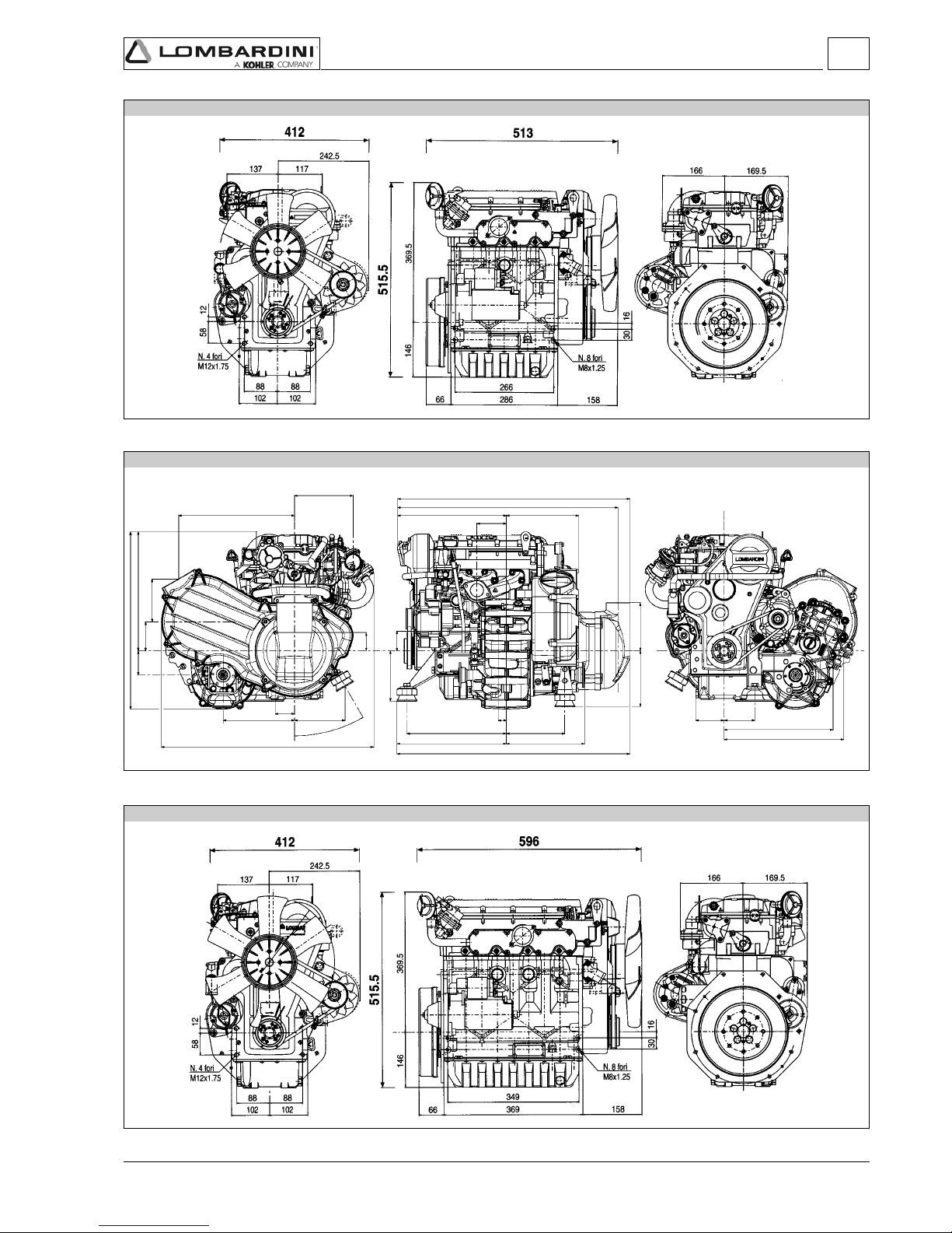
- 23 -
FOCS Workshop Manual_cod. 1.5302.351_7° ed_ rev. 06
LDW 1003
LDW 1404
2
350.2
177
641.8
58.8
152.9215.9
30°
129.3
54.8
87
534.5
359.1
72.9
328.7
685.7
701.7
218
89
703.5
330.5 236.4
300.5 176.5
25
86 93
329
361.8
151.5
59.6
145168.4
Tech nic al i nfo r mat ion
LDW 1003 with EGR circuit, Gear-box and CVT (Continuous Variable Transmission)

- 24 -
FOCS Workshop Manual_cod. 1.5302.351_7° ed_ rev. 06
10 250 300 500 1000 5000 10000
(***)
(**)
(**)
(*)
(*)
(**)
(*)
(*)
(*)
(**)
(**)
(***)
(**)
(**)
(**)
(**)
(°)
(***)
(***)
300
250
33
Important
Failure to carry out the operations described in the table may lead to technical damage to the machine and/or system.
Engine oil replacement.
Oil filter replacement.
ORDINARY MAINTENANCE
AFTER THE FIRST
50 WORKING HOURS
ORDINARY MAINTENANCE
OPERATION DESCRIPTION
FREQUENCY x HOURS
CHECK
REPLACEMENT
OVERHAUL
ENGINE OIL LEVEL
COOLANT LEVEL
AIR FILTER (DRY-TYPE)
RADIATOR EXCHANGE SURFACE
VALVE CLEARANCE ADJUSTMENT
FAN / ALTERNATOR
BELT STRETCH
COOLING LIQUID HOSES
SETTING AND INJECTORS CLEANING
FUEL PIPES
RUBBER INTAKE HOSE (AIR FILTER AND
INTAKE MANIFOLD)
INTERIOR RADIATOR CLEANING
ALTERNATOR AND
STARTING MOTOR
ENGINE OIL
OIL FILTER
FUEL FILTER
ALTERNATOR BELT
COOLANT
FILTER ELEMENT PANEL AIR FILTER
FUEL PIPES
COOLING LIQUID HOSES
RUBBER INTAKE HOSE (AIR FILTER AND
INTAKE MANIFOLD)
TIMING BELT
DRY AIR CLEANER EXTERNAL
CARTRIDGE
DRY AIR CLEANER INTERNAL
CARTRIDGE
PARTIAL
TOTAL
AFTER 6 CHECKS WITH CLEANING
(*) -In case of low use: every year.
(**) -In case of low use: every 2 years.
(***) -The period of time that must elapse before cleaning or replacing the filter element depends
on the environment in which the engine operates. The air filter must be cleaned and
replaced more frequently In very dusty conditions.
(°) -Once removed, the timing belt should be replaced even if its scheduled motion period is
not over.
EVERY 4000 HOURS
AFTER 3 CHECKS WITH CLEANING
MAINTENANCE - RECOMMENDED OIL TYPE - REFILLING
ENHANCED OIL SUMP
STANDARD OIL SUMP
ROUTINE ENGINE MAINTENANCE

- 25 -
FOCS Workshop Manual_cod. 1.5302.351_7° ed_ rev. 06
CF CE CD CC CB CA SA SB SC SD SE SF SG
L - 2104 D / E
L - 46152 B / C / D / E
SH
API SJ
SLCH-4 CG-4 CF-4 CF-2
MIL
3
SAE 20W*
SAE 30*
SAE 40*
SAE 10W-30**
SAE 10W-40**
SAE 10W-60**
SAE 15W-40 **
SAE 15W-40 **
SAE 20W-60 **
SAE 5W-30 ***
SAE 0W-30 ***
-30-2520
-15-105
0+5+10+15+20
+25+30+
35
+40+
45
SAE 10W*
+
50
-35-
40
SAE 5W-40 ***
International specifications
They define testing performances and procedures that the lubricants need to successfully respond to in several engine testing
and laboratory analysis so as to be considered qualified and in conformity to the regulations set for each lubrication kind.
A.P.I : ( American Petroleum Institute )
MIL : Engine oil U.S. military specifications released for logistic reasons
ACEA : European Automobile Manufacturers Association
Tables shown on this page are of useful reference when buying a kind of oil.
Codes are usually printed-out on the oil container and the understanding of their meaning is useful for comparing different brands
and choosing the kind with the right characteristics.
Usually a specification showing a following letter or number is preferable to one with a preceding letter or number.
An SF oil, for instance, is more performing than a SE oil but less performing than a SG one.
API / MIL Sequences
PETROL
A1 = Low-viscosity, for frictions reduction
A2 = Standard
A3 = High performances
LIGHT DUTY DIESEL ENGINES
B1 = Low-viscosity, for frictions reduction
B2 = Standard
B3 =High performances (indirect injection)
B4 = High quality (direct injection)
HEAVY DUTY DIESEL ENGINES
E1 = OBSOLETE
E2 = Standard
E3 = Heavy conditions (Euro 1 - Euro 2 engines )
E4 = Heavy conditions (Euro 1 - Euro 2 - Euro 3 engines )
E5 =High performances in heavy conditions (Euro 1 - Euro 2 -
Euro 3 engines )
ACEA Regualtions - ACEA Sequences
OBSOLETE
DIESEL
PETROL
CURRENT
LUBRICANT
SAE Classification
In the SAE classification, oils differ on the basis of their
viscosity, and no other qualitative characteristic is taken
into account.
The first number refers to the viscosity when the engine is
cold (symbol W = winter), while the second considers
viscosity with the engine at régime.
The criteria for choosing must consider, during winter, the
lowest outside temperature to which the engine will be
subject and the highest functioning temperature during
summer.
Single-degree oils are normally used when the running
temperature varies scarcely.
Multi-degree oil is less sensitive to temperature
changes.
* Mineral base
** Semi-synthetic base
*** Synthetic base
SAE- Grade
Maintenance - Recommended oil type - Refilling

- 26 -
FOCS Workshop Manual_cod. 1.5302.351_7° ed_ rev. 06
AGIP SINT 2000
5W40
API SJ/CF
ACEA A3-96 B3-96
MIL - L-46152 D/E
3
LDW 1204/T
4,3
-
4,1
-
LDW 1404
LDW 1204
LDW 903
LDW 1003
LDW 602
LDW 702
LDW 502
1,5
2,5
1,4
2,4
1,6
2,5
1,5
2,4
2,4
3,8
2,3
3,7
3,2
5,2
3,0
5,0
3,2
5,2
3,0
5,1
specifications
PRESCRIBED LUBRICANT
In the countries where AGIP products are not available, use oil API CF/SH for Diesel engines or oil corresponding to the
military specification MIL-L-2104 C/46152 D.
CHD ENGINES OIL CAPACITY
OIL VOLUME AT MAX
LEVEL
(OIL FILTER INCLUDED)
OIL VOLUME AT MAX
LEVEL
(WITHOUT OIL FILTER)
Litres
Litres
Sheet STD oil sump.
ENHANCED aluminium oil
sump.
Sheet STD oil sump.
ENHANCED aluminium oil
sump.
* With dynamic balancer
Important
If you are using oil of a quality lower than the prescribed one then you will have to replace it every 125 hours for the
standard sump and every 150 hours for the enhanced sump.
Danger – Attention
-The engine may be damaged if operated with insufficient lube oil. It is also dangerous to supply too much lube oil
to the engine because a sudden increase in engine rpm could be caused by its combustion.
-Use proper lube oil preserve your engine. Good quality or poor quality of the lubricating oil has an affect on engine
performance and life.
-If inferior oil is used, or if your engine oil is not changed regularly, the risk of piston seizure, piston ring sticking,
and accelerated wear of the cylinder liner, bearing and other moving components increases significantly.
-Always use oil with the right viscosity for the ambient temperature in which your engine is being operated.
Danger – Attention
-The used engine oil can cause skin-cancer if kept frequently in contact for prolonged periods.
-If contact with oil cannot be avoided, wash carefully your hands with water and soap as soon as possible.
-Do not disperse the oil in the ambient, as it has a high pollution power.
Maintenance - Recommended oil type - Refilling

- 27 -
FOCS Workshop Manual_cod. 1.5302.351_7° ed_ rev. 06
API CF4 - CG4
API CF - CD - CE
3
1,90
LDW
1204/T
0,90
1,75
1,30
LDW
602-702
LDW
1204-1404
LDW
903-1003
0,75
LDW
502
FUEL SPECIFICATIONS
To achieve optimum performance of the engine, use good quality fuel with certain characteristics:
Cetane number (minimum 51): indicates the ignition quality. A fuel with a low cetane number may cause problems when starting
from cold and have a negative effect on combustion.
Viscosity (2.0/4.5 centistokes at 40°C): this is the resistance to flow and performance may decline if not within the limits.
Density (0.835/0.855 Kg/litre): a low density reduces the power of the engine, and density that is too high increases performance
and opacity of the exhaust
Distillation (85% at 350°): this is an indication of the mixture of different hydrocarbons in the fuel. A high ratio of light
hydrocarbons may have a negative effect on combustion.
Sulphur (maximum 0.05% of the weight): high sulphur content may cause engine wear. In those countries where diesel has a
high sulphur content, it is advisable to lubricate the engine with a high alkaline oil or
alternatively to replace the lubricating oil recommended by the manufacturer more
frequently.
The countries in which diesel normally has a low sulphur content are: Europe, North America and Australia.
FUELS FOR LOW TEMPERATURES
It is possible to run the engine at temperatures below 0°C using special winter fuels. These fuels reduce the formation of paraffin
in diesel at low temperatures. If paraffin forms in the diesel, the fuel filter becomes blocked interrupting the flow of fuel.
Fuel can be: - Summer up to 0°C
-Winter up to -10°C
-Alpine up to -20°C
-Arctic up to -30°C
For all fuel types, the cetane number cannot be lower than 51.
AVIATION KEROSENE AND RME FUELS (BIOFUELS)
The only Aviatin fuels that may be used in this engine are: JP5, JP4, JP8 and JET-A if 5% oil is added.
For more information on Aviation fuels and Biofuels (RME, RSME) please contact the Lombardini applications department.
Fuel with low sulphur content
Fuel with high sulphur content
PRESCRIBED LUBRICANT
ENGINE TYPE
CAPACITY (Litres)
Without radiator
Maintenance - Recommended oil type - Refilling
COOLANT
Danger – Attention
-The fluid coolant circuit is pressurized. Inspections must only be made when the engine has cooled and even in
this case, the radiator or expansion chamber plug must be unscrewed with the utmost caution.
-If an electric fan is installed, do not approach a hot engine since the fan itself could start up even when the
engine is at a standstill.
-Coolant fluid is polluting, it must therefore be disposed of in the correct way. Do not litter.
The anti-freeze protection liquid (AGIP ANTIFREEZE SPEZIAL) must be used mixed with water, preferably decalcified. The
freezing point of the cooling mixture depends on the product concentration in water, it is therefore recommended to use a 50%
diluted mixture which guarantees a certain degree of optimal protection. As well as lowering the freezing point, the permanent
liquid also raises the boiling point.
Coolant refueling
For information concerning the capacity of Lombardini radiators, please contact Lombardini directly.
The total volume for refilling the cooling liquid varies according to the type of engine and radiator.

- 28 -
FOCS Workshop Manual_cod. 1.5302.351_7° ed_ rev. 06
4
Important
To locate specific topics, the reader should refer to the index.
– Besides disassembly and reassembly operations this chapter also includes checking and setting specifications, dimensions,
repair and operating instructions.
– Always use original LOMBARDINI spare parts for proper repair operations.
– The operator must wash, clean and dry components and assemblies before installing them.
– The operator must make sure that the contact surfaces are intact, lubricate the coupling parts and protect those that are
prone to oxidation.
– Before any intervention, the operator should lay out all equipment and tools in such a way as to enable him to carry out
operations correctly and safely.
– For safety and convenience, you are advised to place the engine on a special rotating stand for engine overhauls.
– Before proceeding with operations, make sure that appropriate safety conditions are in place, in order to safeguard the
operator and any persons involved.
– In order to fix assemblies and/or components securely, the operator must tighten the fastening parts in a criss-cross or
alternating pattern.
– Assemblies and/or components with a specific tightening torque must initially be fastened at a level lower than the assigned
value, and then subsequently tightened to the final torque.
DISASSEMBLY / REASSEMBLY
RECOMMENDATIONS FOR OVERHAULS AND TUNING
Important
To locate specific topics, the reader should refer to the index.
– Before any intervention, the operator should lay out all equipment and tools in such a way as to enable him to carry out
operations correctly and safely.
– The operator must comply with the specific measures described in order to avoid errors that might cause damage to the
engine.
– Before carrying out any operation, clean the assemblies and/or components thoroughly and eliminate any deposits or
residual material.
– Wash the components with special detergent and do not use steam or hot water.
– Do not use flammable products (petrol, diesel, etc.) to degrease or wash components. Use special products.
– Dry all washed surfaces and components thoroughly with a jet of air or special cloths before reassembling them.
– Apply a layer of lubricant over all surfaces to protect them against oxidation.
– Check all components for intactness, wear and tear, seizure, cracks and/or faults to be sure that the engine is in good
working condition.
– Some mechanical parts must be replaced en bloc, together with their coupled parts (e.g. valve guide/valve etc.) as specified
in the spare parts catalogue.
Danger - Attention
During repair operations, when using compressed air, wear eye protection.
RECOMMENDATIONS FOR DISASSEMBLING AND ASSEMBLING

- 29 -
FOCS Workshop Manual_cod. 1.5302.351_7° ed_ rev. 06
1
2
4
3
4
Dry type air filter
Danger - Attention
Never clean the filtering element with highly flammable
solvents Danger of explosion!
Important
Blow compressed air crossways over the external part and
inside the cartridge at a pressure no greater than 5 atm or if
necessary knock the front of the cartridge repeatedly against a
flat surface.
Components: 1 Cover
2 Filter element
3 Support
Air filter specifications:
Filtration level = 13÷14 µm.
Filtration area = 4470 cm² per LDW 502, 602, 903, 702, 1003
Filtration area = 7150 cm² per LDW 1204,1404
 See page 24 for periodic maintenance details.
Air restriction switch
Components:
1 Reset buttione
2 .25" Tab connection
Note: The indicator is calibrated at 600÷650 mm of water column
for LDW 502, 602, 702, 903, 1003, 1204, 1404; and 370÷420
mm of water column for LDW 1204/T.
Oil bath air cleaner ( on request )
Important
Check the sealing rings regularly.
Replace the sealing rings if hardening or damage is noted
1 Upper Housing 6 Oil level reference mark
2 Diaphragm Seat 7 Reservoir bowl
3 Diaphragm 8 Outer seal ring
4 Polyurethane upper element 9 Inner seal ring
5 Metal wool lower eleme
Note: Carefully clean the reservoir bowl and both elements with
clean diesel fuel. Blow the lower element dry with
compressed air. Dry the upper element by squeezing out
excess diesel fuel, then drying with suitable cloths.
Fill the reservoir with clean engine oil to the reference mark.
 See page 24 for periodic maintenance and replacement details.
Disassembly / Reassembly

- 30 -
FOCS Workshop Manual_cod. 1.5302.351_7° ed_ rev. 06
5
6
8
7
4
1
1
2
2
2
2
1
4
2
7
6
5
13
10
3
9
8
11
12
Air filter support
The support for air filter 1 incorporates the intake manifold and the
accelerator control box.
Remove all bolts that secure the air filter support 1 to the cylinder
head. Carefully pull the air filter support from the cylinder head.
Using suitable pliers, release the governor spring 2 from the air filter
support assembly.
Replace the gasket 3.
Components:
1. Exhaust manifold
2. E.G.R. Pipe
3. E.G.R. Valve
4. Vacuum pump
5. Three way union
6. Vacuum pump pipe
7. Thermovalve – vacuum pump
connection pipe
8. Vacuum valve – thermovalve
connection pipe
9. Vacuum valve - E.G.R. connection
pipe
10. Thermovalve
11. Vacuum valve
12. ON-OFF sensor control cam
13. Intake duct
Intake manifold – Remote air filter
- Unscrew the the fastening screws (1) that fix the intake duct to
the intake manifold unit.
-Unscrew the two fastening screws (2) of the intake manifold from
the engine crankcase.
-Lift the intake manifold and disengage the hook of the min/max
cylinder from the same manifold (fig. 212).
Disassembly / Reassembly
E.G.R. Circuit

- 31 -
FOCS Workshop Manual_cod. 1.5302.351_7° ed_ rev. 06
4
10
11
9
12
5
5
6
4
9
6
4
Disassembly / Reassembly
E.G.R. Circuit
Operation
The main function of the E.G.R. (Exhaust Gas Recirculation)
system is the reduction in emission of NOx (nitrogen oxides), gases
harmful to people and the environment, via lowering the
combustion temperature.
The system takes a certain quantity of exhaust gas from the
exhaust manifold 1 (fig. 8) via the E.G.R. pipe (2) to the E.G.R.
valve 3.
This valve is opened by the vacuum (created in pipes 6, 7, 8 and 9
by vacuum pump 4; fig. 8) only when:
a) thermovalve 10 placed in contact with the engine refrigerant
fluid reaches a temperature of 40 °C;
b) the on-off sensor control cam 12 opens the vacuum valve 11 at
a determined accelerator position.
Once the E.G.R. valve is opened, the exhaust gas enters the intake
manifold 13 via the intake flange.
The same logic controls the closure of the E.G.R. valve.
Disassembly:
- Disengage the control rod catch (1) with a screwdriver from the
accelerator control rod (2) (fig. 9).
- Disconnect the accelerator control rod (2) from the accelerator
control lever (3) (fig. 9).
- Disconnect the thermovalve – vacuum pump connection pipes
(7, fig. 8) and vacuum valve – thermovalve connection pipe (8,
fig. 8) from the thermovalve.
- Unscrew the two fastening screws (5) that fix the E.G.R. pipe (6)
to the E.G.R. valve (4) (figures 10, 11 and 12).
- Remove the intake manifold. See "Intake manifold – Remote air
filter" on page 30 (Figure 7).
- Unscrew the fastening screw of the E.G.R. pipe support bracket
(9 fig. 10) from the engine crankcase and disengage the E.G.R.
pipe from the exhaust manifold.
Reassembly:
When reassembling pay attention to the repositioning of the
gaskets and to the precise connection of the pipes (6, 7, 8, 9, fig.
8).
These pipes should be carefully fitted on the appropriate
connections.
Tighten the screws to specified torque, see "Table of tightening
torques for the main components" on page 100.
 For the calibration of the E.G.R. system see "E.G.R. calibration"
on page 97.

- 32 -
FOCS Workshop Manual_cod. 1.5302.351_7° ed_ rev. 06
4
15
16
13
14
2
1
1
1
Exhaust maniflod
Danger - Attention
Let the exhaust manifold cool before dismounting to avoid
scalds and burns.
When you dismount the exhaust manifold check that the inside is
properly clean and free from cracks or breaks.
Replace gaskets every time you remove the manifold.
Tighten nuts at 25 Nm.
Vacuum pump and vacuum pump flange
Unscrew the three fastening screws 1 that fix the vacuum pump to
the flange and remove the vacuum pump.
Unscrew the fastening screws that fix the flange to the engine
crankcase and remove it.
Components:
1. Vacuum pump
2. Clic clamp 86-50
3. Vacuum pump flange
4. Vacuum pump gasket-
5. Vacuum pump flange gasket
6. Three-way union for vacuum pump
7. Vacuum pump pipe
8. Screw
9. Screw
When reassembling, tighten the screws (8) that fix the flange to
the cylinder head to the specified torque of 10 Nm, and the screws
(9) that fix the vacuum pump to the flange at the specified torque
of 15 Nm.
Exhaust manifold - engines with EGR
Remove the E.G.R. pipe (1).
Unscrew the locking nuts (2) and remove the exhaust manifold and
the seal.
Note: When reassembling the exhaust manifold, check that the
inside is properly clean and free from cracks or breaks.
Note: Replace the gasket each time the manifold is reassembled.
Tighten the nuts at the prescribed torque of 25 Nm.
Disassembly / Reassembly

- 33 -
FOCS Workshop Manual_cod. 1.5302.351_7° ed_ rev. 06
17
18
19
4
20
Alternator/Cooling fan belt drive
Danger - Attention
Check the belt tension only with the engine off.
Tension adjustment.
Loosen screws 1 and 2.
Adjust the belt tension so that a 100N force at the midpoint of the
belt center (as shown) results in a 10-15mm deflection.
 See page 24 for periodic maintenance details.
Cooling fan
Danger - Attention
Carry out the cooling fan disassembly, only after isolating the
positive battery cable to prevent accidental short-circuiting
and, consequently, the activation of the starter motor.
Carefully clean and check all blades. Replace the fan even if there is
only a single damaged blade.
 See pages 16÷17 for cooling air flow volume.
Fuel tank (optional)
Danger - Attention
To avoid explosions or fire outbreaks, do not smoke or use
naked flames during the operations.
Fuel vapours are highly toxic. Only carry out the operations
outdoors or in a well ventilated place. Keep your face well away
from the plug to prevent harmful vapours from being inhaled.
Dispose of fuel in the correct way and do not litter as it is highly
polluting.
After disconnecting the fuel pipes unscrew the anchoring brackets'
screws and remove the fuel tank.
Completely empty the tank and check that no impurities are found
inside.
Check that cap breather hole is not clogged.
Disassembly / Reassembly

- 34 -
FOCS Workshop Manual_cod. 1.5302.351_7° ed_ rev. 06
21
22
23
4
24
Return pulley
Remove the center bolt 1 and slide the pulley from the engine.
Components:
1 Bolt 6 Bearing
2 Washer 7 Spacer
3 Spacer 8 Bearing
4 Pulley 9 Snap Ring
5 Snap Ring
Note: On remounting thoroughly clean out the threads of screw 1
and tighten at 25 Nm.
Flywheel
Danger - Attention
During dismounting be particularly careful not to let the
flywheel fall, as this can be very dangerous for the operator.
Use protective goggles while removing the starter ring gear.
Unscrew the screws that fasten it to the crankshaft.
In order to replace the ring gear, it is necessary to disassemble the
flywheel.
Cut the ring gear in several places using a chisel and remove it.
Heat the new ring gear uniformly and keep it at a temperature of
300°C for 15÷20 minutes.
Insert the ring gear into its seat and place it carefully on the rim of the
flywheel.
eave to the ring gear to cool gently before reassembling the flywheel.
When refitting tighten the screws at 80 Nm.
Driving pulley
Important
To loosen or screw in screw 1 at the set torque you must
always stop the crankshaft and not other parts of the engine.
Locking the crankshaft: remove the engine starter and installing the
fixture tool 1460-051.
Remove the pulley, after having unscrewed central screw 1 and
proceed with the four lateral screws.
The central bolt 1 is left-handed.
When reassembling, apply some Moly-slip antiseizure compound
on the screw thread and tighten at 360 Nm.
Note: When pulley reference mark (A) aligns with the timing cover
reference mark (B), the flywheel side piston is at TDC.
Disassembly / Reassembly

- 35 -
FOCS Workshop Manual_cod. 1.5302.351_7° ed_ rev. 06
4
25
26
27
Ringfeder-type rings on LDW 1204-1204/T-1404
It is possible to draw ¾ of the power from the second drive of LDW
1204-1204/T-1404 engines.
If you want to draw the entire power it is necessary to mount the
Ringfeder rings on the crankshaft handle.
Components:
1 Puleggia appropriata 6 Ringfeder external ring
2 Screw M6 7 Spacer flange
3 Screw M16 x 1,5 8 Shoulder plate
4 Ringfeder internal ring 9 Crankshaft
5 Screw M8
Ringfeder-type rings on LDW 1204-1204/T-1404 - Assembly
Refer to figures 25 and 26.
Clean and oil the parts involved in the mounting with engine oil.
Insert into pulley 1, the internal ring 4 and the external ring 6, then
flange 7 by tightening it temporarily with its screws.
Before assembling the pulley 1 in the crankshaft taper, insert
shoulder ring 8.
Lock the crankshaft using tool 7107-1460-051.
Tighten the screws 2 at a torque of 10 Nm.
Tighten the screws 3 at a torque of 360 Nm.
Tighten the screws 5 uniformly in criss-cross pattern in three
distinct phases:
1° phase = 15 Nm
2° phase = 35 Nm
3° phase = torque check.
Timing belt cover
Loosen the five screws and remove the cover.
When rifitting tighten the screws at a torque of 10 Nm.
Check the peripheral rubber sealing gasket and the two dustprotection rings of the two pulleys, if mounted.
Disassembly / Reassembly

- 36 -
FOCS Workshop Manual_cod. 1.5302.351_7° ed_ rev. 06
28
29
31
30
32
4
33
Tightening pulley
Components:
1 Nut
2 Washer
3 Pulley
4 Bearing
5 Shaft/Support
6 Mounting plate
7 Tensioning lever
Timing belt removal
Important
When you remove the distributor belt replace it even if its
prescribed operation time has not expired yet.
Danger – Attention
Always check that the positive pole of the battery is insulated.
Remove the belt tensioner 1.
Remove the timing belt off the timing pulley.
 For assembly see fig. 36.
Timing belt / Timing pulley arrangement
Components:
1 Camshaft pulley
2 Timing belt
3 Crankshaft pulley
4 Coolant pump pulley
5 Belt tensioner pulley
Crankshaft timing pulley
Al rimontaggio fare attenzione che la chiavetta rimanga inserita
nella propria sede.
Note: Reference mark 1 on the crankshaft timing pulley and
reference mark 2 on the oil pump housing are timing marks.
When aligned, No. 1 piston (flywheel side) is at TDC.
Disassembly / Reassembly

- 37 -
FOCS Workshop Manual_cod. 1.5302.351_7° ed_ rev. 06
4
34
35
36
37
Camshaft timing pulley - Reference marks
1 Timing reference mark on cylinder head.
2 Camshaft pulley timing mark, for LDW 502 engines only
3 Camshaft pulley timing mark, for LDW 602, 702, 903, 1003, 1204,
1204/T and 1404 engines.
Camshaft timing pulley - Disassembly/Assembly
Unscrew screw 1 and remove the pulley. No extractor is needed.
When refitting tighten the screw at a torque of 80 Nm.
Note: Assess any wear caused by the lip of the seal ring on the
pulley tang.
Camshaft timing - Belt Reassembly
Important
Remove the distributor toothed belt from its protective
wrapping only when mounting it.
Make the connections for toothed belt fig. 33 and that of pulley fig.
34 fit together.
Insert the belt as in figure 35 taking account of the direction of the
arrows A impressed on it (direction of rotation).
Tighten the nut 1 by hand until the belt tightener rests on surface of
the crankcase.
Start by mounting the camshaft pulley belt, then mount crankshaft’s
pulley.
Do not mount driven belts.
Disassembly / Reassembly

- 38 -
FOCS Workshop Manual_cod. 1.5302.351_7° ed_ rev. 06
39
4
40
38
Camshaft timing - Belt Tightening and Fastening
Insert the torque wrench in the suitable tool so that the A axis of
the key fig. 39 is at 90° to the B axis of the tool in fig. 38.
Tighten in clockwise direction at 20 Nm.
Maintaining the belt tension, tighten nut 3 with another torque
wrench at 40 Nm, after having remounted the drive pulley.
Rotate the crankshaft a few times and check that the tension is as
described above.
The check must be carried out with the appropriate Nippon Denso
tension measuring instrument (halfway along the longest section of
the belt), the value for a cold engine must be 15±2Kg.
Valve timing check
A = Intake valve
B = Exhaust valve
Rotate the engine in the normal direction of rotation until the No. 1
piston (flywheel side) approaches TDC- compression stroke
Check the balance of intake and exhaust valves A and B placing the
two micrometers testers on the valve collars.
Camshaft timing - Belt tightening tool
Position belt preload tool 7107-1460-049 1 over the timing belt idler
adjustment ear 2.
See "Camshaft timing - Belt Tightening and Fastening".
Disassembly / Reassembly

- 39 -
FOCS Workshop Manual_cod. 1.5302.351_7° ed_ rev. 06
4
41
Valve timing - Angles
The angle values are determined by turning the driving shaft
clockwise.
S =Piston at top dead centre
I =Piston at bottom dead centre
αα
αα
α =Intake valve open
ββ
ββ
β =Intake valve closed
γγ
γγ
γ =Exhaust valve open
δδ
δδ
δ =Exhaust valve closed
Timing angles for operating purposes
(valve clearance = 0.25 mm)
αα
αα
α =16° before S
ββ
ββ
β =36° after I
γγ
γγ
γ =36° before I
δδ
δδ
δ =16° after S
Timing angles for checking puposes
(valve clearance = 2 mm)
αα
αα
α =21° after S
ββ
ββ
β =closes in I
γγ
γγ
γ =2° after I
δδ
δδ
δ =20° before S
Timing angles for operating purposes - LDW 1204/T
(valve clearance = 0.25 mm)
αα
αα
α =10° before S
ββ
ββ
β =42° after I
γγ
γγ
γ =56° before I
δδ
δδ
δ =16° after S
Timing angles for checking puposes - LDW 1204/T
(valve clearance = 2 mm)
αα
αα
α =31° after S
ββ
ββ
β =1° after I
γγ
γγ
γ =11° before I
δδ
δδ
δ =29° before S
Disassembly / Reassembly

- 40 -
FOCS Workshop Manual_cod. 1.5302.351_7° ed_ rev. 06
42
44
45
48
43
46
4
SPEED GOVERNOR
The weight-type mechanical governor, is driven directly by the
camshaft and is housed with the cylinder head.
Components:
1 Thrust washer
2 Spool
3 Flyweight assembly
Note: In engines with the minimum/maximum (see fig. 49) the
weights are lightened by 25%.
Governor springs for Gensets
In the section view of the leverages the 4 ball bearings A are
highlighted.
They are mounted on engines for generator sets adjusted at
1,500÷1,800 rpm and on other particular applications on request.
Governor springs
Unscrew the pin that attaches it to the cylinder head.
To remove it as shown in the figure it is necessary to dismount the
camshaft. It could also be removed from the accelerator box side by
unscrewing the torque gearing device.
Before reassembling it, check value A (45 to 46 mm) and the
parallelism of the two levels B that must not exceed 0.05 mm.
Note: There are 5 different types of regulator springs C. These
change according to the engine adjustment: standard spring
for 3,600 rpm, for 3,000 rpm, for 2,400 to 2,600 rpm, for
1,800 rpm and for 1,500 rpm.
Speed governor components
1 Oil seal
2 Screw
3 Support
4 O-Ring
5 Bearing
6 Retainer
7 Screw
8 Flyweight assembly
9 Spool
10 Thrust washer
Disassembly / Reassembly

- 41 -
FOCS Workshop Manual_cod. 1.5302.351_7° ed_ rev. 06
4
49
50
Speed governor - Limiting speed governor
With applications for the automotive sector the regulator spring C
fig. 45 is replaced by a device (plunger barrel) that only enables a
constant speed at the minimum and maximum rpm rating.
Components:
1 Nut
2 Idle speed spring
3 Max. speed spring
4 Case
5 Register
6 Spring ring
7 Actuation rod
Note: There are six maximum springs in a different colours, to
distinguish them from the six respective adjustments.
Red color for ...................... 3000 giri/1'
No color ............................. 3200 giri/1'
Black .................................. 3600 giri/1'
Orange ............................... 3750 giri/1'
White.................................. 4200 giri/1'
Green ................................. 4300 giri/1'.
Brown ................................. 4500 giri/1'
Speed governor - Reassembly
Caution – Warning
While reassembling, check the integrity of the components
and check that they operate correctly.
Bad operation of the speed governor can cause serious
damage to the engine and to people being near to it.
Remount in reverse order to Fig. 44.
When inserting the bearing in the camshaft, do it so that the four
blocks enter opened, so that they can receive the hose and close
over it.
Check the integrity of the sealing rings of the cover.
Ti ghten t he thre e screw s at a torq ue of 10 Nm .
Note: With the speed governor mounted the camshaft axial
clearance should be zero.
Disassembly / Reassembly
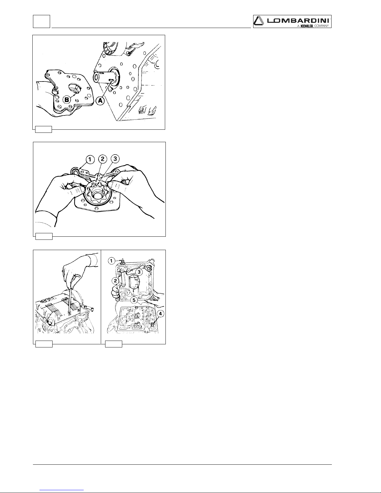
- 42 -
FOCS Workshop Manual_cod. 1.5302.351_7° ed_ rev. 06
51
52
53 54
4
Oil pump - Reassembly
The pump rotors should be coupled on the same side, see
references 2 and 3.
Replace the O-ring 1.
Tighten the fastening screws to the crankcase at 25 Nm and those
of the plate at 10 Nm.
 See page 69 for technical details.
Oil pump - disassembly
The FOCS oil pump is supplied as an assembly. Lombardini
therefore recommends that the oil pump be handled as an assembly
from a service standpoint
Lombardini does not recommend that the oil pump be disassembled,
then reassembled for purposes of installation on the engine except
during emergency situations.
Rotate the crankshaft until the crankshaft timing pulley keyway is
vertical as shown. Remove the oil pump assembly retaining bolts.
When the crankshaft timing pulley keyway is vertical, the oil pump
drive keyway (A) will be at 3:00 o’clock allowing removal of the oil
pump assembly via relief (B).
Rocker arm cover
The engine control components are all on the cylinder head.
The cover contains part of the lubrication duct of the camshaft and
of the rocker arms, as well as part of the engine vent system.
Components:
1 Oil preassure switch
2 Camshaft lubrification port
3 Rocker arm lubrification port
4 Oil exhaust hose from sump vent system
5 Air valve with oil decanting wire gauze
Note: During remounting be careful with oil exhaust hose 4 that
needs to be properly inserted into its housing on the cylinder
head.
Disassembly / Reassembly

- 43 -
FOCS Workshop Manual_cod. 1.5302.351_7° ed_ rev. 06
55
4
56 57
58
Rocker arm cover gasket
The rocker arm cover gasket A ensures the seal of the lubrication
circuit for the camshaft and rocker arm shaft.
Always replace it and mount it with especial care above all in zones
1 and 2 where, for greater safety, it is advisable to apply a few
drops of silicon sealant.
Tighten the rocker arm cover screws at a torque of 9 Nm.
Crankcase vacuum regulator valve
Components:
1 Gland Nut
2 Bushing
3 Body
4 Diaphragm
5 Cap / Cover
6 Clip / Lock
7 O-Ring
8 Washer
9 O-Ring
10 Valve
11 Spring
12 Tube
13 Hose
The vacuum relief valve is an engine safety device.
Its function is that of limiting the vacuum whenever it tends to
increase.
Without this, should the air filter be clogged, the oil contained in the
carter may be sucked back into intake manifold causing the
condition for engine runaway.
Disassembly / Reassembly

- 44 -
FOCS Workshop Manual_cod. 1.5302.351_7° ed_ rev. 06
59
60
62
64
61
63
4
Valve / Rocker ar m clearance
Important
Setting should be performed when the engine is cold.
Bring each cylinder piston to top dead center on the compression
stroke and set clearance A at 0,20 mm for both the intake and
exhaust valves.
For greater convenience, clearance check B is accepted. In this case
the value is 0.15 mm.
Crankcase breather LDW 502
For LDW 602-702-903-1003-1204-1204/T-1404 engines, the exhaust
gases exit from the cylinder head cover, see Fig. 53, 54.
In the LDW 502 engine the exhaust gases exit directly from the
crankcase via cover 1.
Remove the cover, check the integrity of the air valve and oil
decanting wire gauze.
Fuel rail
When removing the fuel feeding pumps A, with the rail holders B,
pay attention that the sealing O-rings C remain in their seats.
When refitting tighten the rail holder screws at a torque of 4 Nm.
Injection pump control rod
Depending on the engine model, the injection pump control rod will
link two, three, or four injectors to the engine governor.
Screws 1 and 2 are pivoted on the delivery control lever of each
pump/injector B, unscrew the screws and remove spring 3.
When refitting tighten the screws 1 and 2 at a torque of 1,1 Nm
and make sure that they stop on lever B of each pump/injector and
not on rod A.
 To carry out the delivery equalisation of the injection pumps see
page 83.
 To carry out the timing of the injection pumps and speed
governor see page 95
Disassembly / Reassembly

- 45 -
FOCS Workshop Manual_cod. 1.5302.351_7° ed_ rev. 06
4021-309-206-205WDL
BDE
58,1÷0,10,6÷52,51,7÷0,7
T/4021WDL
BDE
51,1÷5,0
5,6÷59,5
1,7÷0,7
65 66
4
67
68
Pump/injector unit - non-return valve
Non-return valve A immediately stops the engine whenever the stop
is activated.
Dimensions (mm):
Note: If the value of B is not achieved, the two rings C are not
subject to enough compression to ensure the seal; any fuel
loss would contaminate the lubrication oil and consequently
damage the engine, F = metal gasket.
Pump/injector unit - Disassembly
When the removal (but not replacement) of a unit injector is
required the following procedure may be used to avoid the need for
other adjustments:
Rotate the engine until the unit injector cam lobe 2 forces the cam
follower 1 to the highest position, then insert a suitable sized
(hardened) pin into the hole 3 and rotate the engine until the cam
follower 1 is at the lowest position. In this way the injection advance
regulator 4 remains calibrated.
Note: If you dismount more than one pump/injector unit, make
sure to reinstall them in the appropriate housing (with
relative drive rod 5); before mounting lubricate the drive rod
at its two ends with MOLYSLIP, AS COMPOUND 40 type.
Rocker arm assembly
Remove the nuts attaching the rocker arm assembly to the cylinder
head.
When refitting tighten the nuts at a torque of 40 Nm.
The pin, that is hollow inside to allow lubrication, is closed at its
ends by two caps.
Note: The rocker arm assembly may be removed without removal
of the unit injectors.
Disassembly / Reassembly

- 46 -
FOCS Workshop Manual_cod. 1.5302.351_7° ed_ rev. 06
mm
B-C
B-C
A
00,1÷0
B
000,81÷989,71
140,0÷510,0090,0
C
030,81÷510,81
69
71
73
70
72
74
4
limit value
Rocker arm pivot, dismounting and remounting
To remove pivot 1 from the support 2 it's necessary to drill out pin 3
using a 4mm drill bit.
On remounting insert a new pin and reinsert it in bearing surface A
(0 to 1 mm).
Check the rod’s state of wear and tear (diam. B) and that of the
rocker arm holes (diam. C).
Remove the closing caps 4 at the end and carefully clean inside.
Dimensions (mm):
Camshaft, disassembly
Loosen the screws and remove the cover 1.
Check gasket ring 2 for integrity.
Remove the drive rod from the fuel pump.
Gently remove the camshaft, slight rotations may be required to
avoid binding the camshaft lobes against the camshaft bearing
surface bores.
Note: The lift pump drive eccentric 3 is included on the flywheel end
of the camshaft and fixed with a screw.
In case of replacement tighten the eccentric screw at a torque of 80
Nm.
Camshaft, journal and housing measurement
Use an inside micrometer gauge for housing diameters and an outside
micrometer gauge for journal diameters.
Disassembly / Reassembly

- 47 -
FOCS Workshop Manual_cod. 1.5302.351_7° ed_ rev. 06
ABB-A
B-A
060,73÷530,73000,73÷579,63580,0÷530,0071,0
75
76
4
77
Camshaft journals and housings - Dimensions (mm)
Note: The camshaft journal and cylinder head camshaft bore
dimensions are identical for all LDW-FOCS series engines
(LDW 502-602-702-903-1003-1204-1204/T-1404).
limit value
Camshaft lobe measurement
Use an outside micrometer gauge.
Intake / Exhaust / Injection camshaft lobe height - LDW 903
A1 = 1st cylinder intake camshaft lobe
A2 = 2nd cylinder intake camshaft lobe
A3 = 3rd cylinder intake camshaft lobe
I1 = 1st cylinder injection camshaft lobe
I2 = 2nd cylinder injection camshaft lobe
I3 = 3rd cylinder injection camshaft lobe
S1 = 1st cylinder exhaust camshaft lobe
S2 = 1st cylinder exhaust camshaft lobe
S3 = 1st cylinder exhaust camshaft lobe
H = 29,598÷29,650 mm (intake/exhaust camshaft lobe height)
H1 = 28,948÷29,000 mm (injection camshaft lobe height)
For 1204/T : H (intake) = 29,438÷29,490 mm,
H (exhaust) = 29,778÷29,830 mm.
All engines in the series (except LDW 1204/T) have intake exhaust
and injection cams with the same height of H and H1.
If wears on the cams exceeds by 0.1 mm the minimum value given
H and H1, replace the crankshaft.
Disassembly / Reassembly

- 48 -
FOCS Workshop Manual_cod. 1.5302.351_7° ed_ rev. 06
78
79
81
80
82
4
83
CYLINDER HEAD, removal
Important
Do not remove the cylinder head when hot to avoid
deformation.
lf cylinder head is deformed by more than 0.10 mm, level it off by
removing a maximum of 0.20 mm.
 For the cylinder head tightening procedure see page 57.
Valves
To remove the valves it is necessary to remove the collets; place a
spacer under the valve head, press strongly on the spring cap as
shown in the picture.
Components: 1 Valve stem
2 Valve stem seal ring
3 Spring seat
4 Spring
5 Spring cap
6 Collets
Valve stem sealing rings - Reassembly
To prevent deformation of the sealing ring 1 as it is inserted onto the
valve guide, insert it onto tool "7107-1460-047" 2 (after lubricating
the sealing ring) and proceed as shown int the picture ensuring that
gasket 1 is completely fitted.
Valve springs
Measure free height with a gauge.
Free height A = 46 mm.
Note: If the free height A is less than 43,5 mm replace the spring.
Disassembly / Reassembly

- 49 -
FOCS Workshop Manual_cod. 1.5302.351_7° ed_ rev. 06
4
84
T/4021-4021-309-206-2054041-3001-207
D 00,92
02,0354°54÷'03°54
T/4021-4021-309-206-2054041-3001-207
C 00,33
04,43
'
54°06÷'03°06
αα
αα
α
1
αα
αα
α
AB CDE
6,63÷4,63450,11÷540,11810,11÷000,1102,6÷08,558,9÷57,9
ABC
0,04÷5,93020,7÷500,7099,6÷069,6
85
86
Valve, specifications
Exhaust valve A
Shaft and head are made of 2 different materials.
2 Welded joint
3 Chromium-plated joint
4 Portion made of:........X 45 Cr Si 8 UNI 3992
5 Portion made of:........X 70 Cr Mn NI N 216 UNI 3992
Intake valve B
Material: X 45 Cr Si 8 UNI 3992
1 = Chromium-plated joint
Val ve guides and valv e gu id e ho usings
Both intake and exhasut valve guides are identical dimensionally and
are made from phosphoric gray iron with a pearlitic matrix:
Dimensions (mm):
Note: Valve guides are supplied in finished form,
further machining
is prohibited.
Valve guides with outside diameter B increased by 0.5 mm.
are available.
Valve guide insertion
Fit the guides with a punch taking account of value A in relation to
the cylinder head surface.
Dimensions (mm):
Clearance (mm):
(B-C) = 0,015÷0,050 (B- C) limite usura = 0,10
Disassembly / Reassembly

- 50 -
FOCS Workshop Manual_cod. 1.5302.351_7° ed_ rev. 06
4
87
T/4021-4021-309-206-205WDL
mm
A 540,43÷020,43
°54÷'35°44°06÷'35°95
B 511,43÷601,43
C 140,03÷020,03
D
611,03÷801,03
4041-3001-207WDL
mm
A 542,53÷022,53
°54÷'35°44°06÷'35°95
B 513,53÷603,53
C
142,13÷022,13
D 613,13÷803,13
αα
αα
α
αα
αα
α1
αα
αα
α
αα
αα
α1
88 89
T/4021-4021-309-206-205WDL
mm
D 8,0÷5,0
1,1
S 7,1÷6,1
0,2
4041-3001-207WDL
mm
D 0,1÷7,0
3,1
S 6,1
0,2
Valve seats and housings - Dimensions
Press valve seats into the housings
Note: Valve seatsare supplied in finished form, further machining is
prohibited.
Valve recess and seat sealing width
Dimensions (mm):
Grind valve seats with fine emery paste.
After grinding check the valve recess D relative to the cylinder head
surface and the seat sealing width S.
Disassembly / Reassembly

- 51 -
FOCS Workshop Manual_cod. 1.5302.351_7° ed_ rev. 06
4
90
91 92
93
95
94
96
Pre-combustion chamber
Components:
1 Pre-combustion chamber
2 Pre-heating glow plug
3 Pre-combustion chamber ring nut
4 Cylinder head
The pre-combustion chamber does not normally require removal or
service, if service is necessary follow the procedure described below.
Pre-combustion chamber ring nut removal
The pre-combustion chamber is fixed to the cylinder head by a ring
nut, so before removing the pre-combustion chamber it is necessary
to unscrew the pre-combustion chamber ring nut.
Use the special tool "7107-1460-027" 1 to romve the ring nut 2.
Pre-combustion chamber, removal
Before proceeding with removing the pre-combustion chamber it is
necessary to remove the pre-heating glow plug.
Screw special tool "7107-1460-030" 1 into the pre-combustion
chamber.
Carefully, but sharply, slide the slide hammer 2 up the special tool
shaft until contact is made with end of the tool. The hammer effect of
the special tool will extract the pre-combustion chamber 3.
Note: There are many types of precombustion chambers for the
various engines described as follows.
- LDW 502
- LDW 602-903-1204-1204/T.
- LDW 702-1003-1404.
Pre-combustion chamber, installation
The pre-combustion chamber has a hole on the side where the preheating glow plug 2 must be inserted.
When re-fitting introduce the the new pre-combustion chamber into
the cylinder head so that the side hole of the pre-combustion
chamber aligns with the glow-plug hole.
To make sure that both the holes align appropriately use tool "71071460-031" 1 inserting it into the glow-plug hole.
Tighten the ring nut twice:
1st tighten at a torque of 100 Nm,
2nd tighten at a torque of 180 Nm.
Chack that clearance A is 3,68÷4,1 mm.
Disassembly / Reassembly

- 52 -
FOCS Workshop Manual_cod. 1.5302.351_7° ed_ rev. 06
97 98
4
99
101
100
102
Oil pan, removal
Danger - Attention
-The used engine oil can cause skin-cancer if kept frequently
in contact for prolonged periods.
-If contact with oil cannot be avoided, wash carefully your
hands with water and soap as soon as possible.
-Do not disperse the oil in the ambient, as it has a high
pollution power.
Remove the fixing screws.
Insert a spacer 1 in the forward and rear main bearings.
Detach the silicon from the main bearing rubber bulb seals.
When re-mounting apply Silicone " Dow Corning 7091" as shown
in the picture.
Tighten the screws at a torque of 10 Nm.
Before starting the engine make sure that:
1) the oil drain plug is tightened correctly
2) the engine has been refilled with the prescribed quantity of oil (see
page 26).
PISTON
Remove the connecting rod big end cap.
Remove the piston-connecting rod assembly.
Note: The LDW 502’s piston is different from the LDW 602 in
terms of its combustion chamber.
The LDW 1204/T piston is different from that of the LDW
1204 in term of its cooling nozzle’s slot bleed and an insert
in the first section’s hollow.
The Ricardo type of combustion chamber is used for LDW
702-1003-1404 engines.
Stop pin rings, dismounting and remounting
Extract the ring inserting a pointed tool in hollow A.
On remounting, insert rings with the points turned downwards inside
the corners (
αα
αα
α = 15°).
Disassembly / Reassembly

- 53 -
FOCS Workshop Manual_cod. 1.5302.351_7° ed_ rev. 06
4
103
T/4021-4021-309-206-205WDL
A 000,27÷099,17
049,17÷039,17
070,0÷050,0
B 010,27÷000,27
059,17÷049,17
C 020,27÷010,27
069,17÷059,17
4041-3001-207WDL
A 000,57÷099,47
049,47÷039,47
070,0÷050,0
B
010,57÷000,57059,47÷049,47
C 020,57÷010,57
069,47÷059,47
Piston, disassembly and inspection
Remove the stop rings and remove the pin, see fig. 101.
Remove the piston rings and clean the slot.
Measure diameter Q at height A from the base of skirt (A = 9 mm).
If the diameter is worn more than the 0.05 mm minimum given
value, replace piston and rings.
Note: The provided oversize elements are of 0.50 mm and 1.00 mm
Piston, class
The pistons are subdivided according to their diameters into categories: A, B, C. These references, are shown on the top of
the piston (see fig. 100).
Piston supply:
Pistons at the nominal diameter are only supplied in category A.
Pistons oversized by 0.50 and 1.00 mm are supplied with reference to the increased level on the piston crown:
Ø 72.5 - Ø 73 for LDW 502-602-906-1204-1204/T engines and Ø 75.5 – 76.0 for LDW 702-1003-1404 engines.
Class Ø Cylinder - mm Ø Piston - mm Clearance - mm
Class Ø Cylinder - mm Ø Piston - mm Clearance - mm
Disassembly / Reassembly

- 54 -
FOCS Workshop Manual_cod. 1.5302.351_7° ed_ rev. 06
A
°154,0÷52,0
0.1°254.0÷52,0
°354,0÷02,0
105
4
106 107
A
521,0÷090,0
B
580,0÷050.0
C
570,0÷040,0
104
limit value
Piston ring
Piston rings - End gaps (mm)
Place piston rings squarely into the unworn part of the lower cylinder
and measure the end gap A.
Piston ring, Clearance between grooves (mm)
Piston, weight
Weigh pistons when replacing them in order to avoid unbalance.
Important
The difference in weight should not exceed 4 g.
Disassembly / Reassembly

- 55 -
FOCS Workshop Manual_cod. 1.5302.351_7° ed_ rev. 06
4
108
109
111
110
Piston ring, mounting order
A = 1° ring (internal tapered and torsional)
B = 2° ring (internal tapered and torsional)
C = 3° Oil control ring
D = Chrome-plated area
E = Chrome-plated area
Note: When there is writing on the surface of a piston ring, mount
that surface with face upward.
Piston clearance
The piston in the TDC (top dead centre) position may extend or be
short of the upper surface of the cylinder.
Determinare the clearance of each piston using a dial indicator to
measure the difference between the two surfaces (piston crown and
upper cylinder surface).
To determine the piston clearance and, by consequence, which
copper gaske is most suitable it is necessary to consider the A value
of the piston that projects furthest.
Piston, assembly
Important
Before re-mounting lubrificate the piston pin, piston, cylinder
and conncecting rod big end bearing.
Couple the piston to the connecting rod inserting the pin, after
lubricating it, just via thumb pressure.
Insert the two pin stop rings and check that they are properly
housed in their seats, see fig. 101.
Using piston ring compression pliers, introduce the piston into the
cylinder so that combustion chamber A is directly under the
precombustion chamber parallel to the head.
Couple the piston/connecting rod to the crankshaft.
 For tightening the head/connecting rod see fig. 115-116.
Disassembly / Reassembly

- 56 -
FOCS Workshop Manual_cod. 1.5302.351_7° ed_ rev. 06
309-206-205WDL
)mm(A
60.1÷79.0
84.0÷93.0
61.1÷70.1
52.1÷71.184.0÷04.0
T/4021-4021WDL
)mm(A
60.1÷79.0
84.0÷93.0
61.1÷70.1
52.1÷71.184.0÷04.0
3001-207WDL
)mm(A
19.0÷28.0
36.0÷45.0
10.1÷09.0
01.1÷20.136.0÷55.0
4041WDL
)mm(A
19.0÷28.0
16.0÷25.0
10.1÷29.0
01.1÷20.116.0÷35.0
112
4
Head gasket
Important
Remove the cylinder head gasket seal from its protective
covering only when you are going to mount it.
The gasket thickness is identified by the number of notches located
in point B.
Choose the appropriate gasket considering that each A value on
the table corresponds to a gasket with: no hole, one hole, two
holes, or for the 1404 one notch, two notches, three notches.
The A value relates to figure 111.
Each time you dismount the head you must replace the gasket.
N° of holes Piston clearance
0 holes
1 hole
2 holes
N° of holes Piston clearance
1 hole
2 holes
3 holes
N° of holes Piston clearance
1 hole
2 holes
3 holes
N° of notches Piston clearance
1 notch
2 notches
3 notches
Disassembly / Reassembly

- 57 -
FOCS Workshop Manual_cod. 1.5302.351_7° ed_ rev. 06
4
113
114
115
Cylinder head assembly
Use a torque wrench equipped with a device for angular tightening.
Measure the length of each screw (normal length = 89.5÷90.5 mm).
Replace it if it exceeds 92 mm.
Proceed as follows.
Cylinder head tightening procedure LDW 1204-1204/T-1404
Following the numerical order shown in the diagram, the bolts must
be tightened in three phases:
1
st
phase = 50 Nm
2nd phase = Rotate the wrench 90° in a clockwise direction.
3rd phase = Rotate the wrench again 90° in a clockwise direction.
Cylinder head tightening procedure LDW 502-602-702-903-1003
Important
Once the head has been correctly tightened, it should not be
retightened except if it is disassembled again.
Before mounting it is advisable to lubricate stem, shank and
underhead of screws with SPARTAN SAE 460 oil.
A = For LDW 502-602-702 models
B = For LDW 903-1003 models
Following the numerical order shown in the diagram, the bolts must
be tightened in three phases:
1
st
phase = 50 Nm
2nd phase = Rotate the wrench 90° in a clockwise direction.
3rd phase = Rotate the wrench again 90° in a clockwise direction.
For LDW 502 with pressure cast (aluminium) crankcase:
With head H tightening bolts: 1st phase = 60 Nm
With head 8.8 tightening bolts: 1st phase = 40 Nm
2nd phase = Eseguire una rotazione
della chiave in senso
orario di 90°.
3rd phase = Proseguire con una
rotazione della chiave in
senso orario di 90°.
Disassembly / Reassembly

- 58 -
FOCS Workshop Manual_cod. 1.5302.351_7° ed_ rev. 06
116
117
119
118
4
CONNECTING ROD
Caution – Warning
While reassembling the big end bearings, we suggest cleaning
all parts thoroughly, as well as proper greasing in order to
avoid risks of seizure at the first start.
Big end bearing
After connecting rod from crankshaft disconnection, check the
following.
While reassembling, be sure the two centring notches A an B are
on the same side.
Tighten the connecting rod big end cap screws simultaneously at
a torque of 40 Nm.
Note: The big end bearing is supplied both at the nominal value
and undersized by 0.25 and 0.50 mm.
In the LDW 502 engine with light alloy crankcase the
connecting rod is aluminium type and not provided with
connecting rod big end bearing and small end bush.
Connecting rod with bearings and pin
Dimensions (mm):
A =126,48÷126,52
=106,98÷107,02..... (for LDW 502)
B =18,015÷18,025
=20,015÷20,025..... (for LDW 702-1003-1204/T-1404)
C =40,021÷40,050..... (bearing tightened at 40 Nm)
D =17,996÷18,000
=19,996÷20,000..... (for LDW 702-1003-1204/T-1404)
E =50,900÷51,100
=54,000÷55,100..... (for LDW 702-1003-1204/T-1404)
(B-D) = 0,015÷0,039 (B-D) limit value = 0,060
Nota: When driving the small end bearing make sure both oilholes
are aligned.
Connecting tod, weight
Weigh connecting rods when replacing them in order to avoid
unbalance.
Important
The difference in weight should not exceed 10 g.
The difference in weight of the pre-assembled connecting rod, piston
and pin must not exceed 14 g.
Disassembly / Reassembly

- 59 -
FOCS Workshop Manual_cod. 1.5302.351_7° ed_ rev. 06
120 121
4
122
124
125
123
Connecting rod alignment
Utilizzare un calibro con piano di riscontro o un comparatore come
in figura.
Controllare l'allineamento degli assi utilizzando lo spinotto del
pistone; lo scarto A = 0,015 mm;. limite 0,030 mm.
Piccole deformazioni si possono correggere sotto una pressa
agendo con sforzi graduali.
CYLINDERS
Reset the dial gauge with a calibrated ring: check the diameter D in
points 1, 2 and 3; repeat the same operation rotating the dial gauge
by 90° at the same heights.
Check any wear in zone X where the piston rings operate and if it is
greater than the 0.05 mm max limit given adjust the cylinder to the
next increased value.
72,000 mm for LDW 502-602-903-1204-1204/T engines;
75,000 mm for LDW 702-1003-1404 engines.
Cylinder roughness
Caution – Warning
Do not treat the cylinder’s internal surfaces with an emery
cloth.
The angle of the crossed processing marks must be between 45°
and 55°. These must be uniform and distinct in both directions.
Average roughness must be between 0.5 and 1 µm.
The whole surface of the cylinder affected by contact with the piston
rings must be rendered with the plateau method.
Cylinder, class
The pistons (A, B, C) locations are shown on the piston crown
while those for the cylinders are found on the crankcase in the
points shown by the arrows, see picture.
Note: For LDW 502 with an aluminium crankcase, the cast iron
cylinders can be adjusted normally to increase values by 0.5
and 1.0 mm.
The cylinders are not to be changed.
Disassembly / Reassembly

- 60 -
FOCS Workshop Manual_cod. 1.5302.351_7° ed_ rev. 06
126
127
129
128
130
4
Rear and forward main bearing caps
Important
Before the final tightening, check the coplanarity of the two
levels with a ground bar
On remounting the rear main bearing cap 1 replace the lateral
rubber gaskets 2, keeping in mind that projections A and B of the
support must be 0,5÷1,0 mm; cut off any exceeding portions.
Do the same with the front bearing cap.
Before reintroducing the bearings in the crankcase, place between
their surfaces two plates C and D - 0.1 mm thick - se.no.71071460-053.
Tighten the screws at a torque of 60 Nm.
Note: It is advisable to apply a few drops of silicon sealant on the
surface of the gasket slot 2.
Central main bearing caps
The central support caps are marked with locations that can be
numbers as in the diagram or dots.
The same locations are given on the crankcase.
Couple the caps with the same references and on the same side. In
any case locate the bearing’s two centring notches that are to be
found on the same side.
Tighten the screws simultaneously at a torque of 60 Nm.
Check the clearances between the bearings and the journal
Use the ”Perfect Circle Plastigage” type calibrated wire A and put it
at the centre of the bearing with a bit of grease.
Tighten the screws at a torque of 60 Nm.
Find out the clearance value checking the wire’s compression with
the appropriate graduated scale supplied in the same pack and
available on the market.
 For clearance values between the journals, connecting rod pin
and the relevant bearings see page 64.
Disassembly / Reassembly

- 61 -
FOCS Workshop Manual_cod. 1.5302.351_7° ed_ rev. 06
ABCD
58,0÷08,04305161°5
αα
αα
α
131 132
4
133
134 135
A mm
313,0÷031,05,0
B mm
01,32÷50,3205,32
Piston coolant nozzles
Caution – Warning
The piston has a recess so that during up-down movements
and vice versa it cannot come into contact with the nozzle.
When remounting the nozzle be careful that it is placed so that
when the piston goes past it is in the
centre of the recess.
They are in the supercharged LDW 1204/T engine and are housed
near the main bearings.
Components:
1 Washer
2 Nozzle
3 Washer
4 Joint (tighten to 12Nm)
5 Valve (opening pressure = 1÷1.2 bar)
6 Spring
Characteristics (mm):
Shoulder half rings
So as to keep them in their seats during assembly, put a bit of
grease.
The half-rings must be assembled with the slots A as in the figure.
Thickness of half-rings is equal to 2.31÷2.36 mm.
They are supplied as spare parts as increased thickness 0.1 and 0.2
mm, see below.
Crankshaft axial clearance
After tightening the main bearings measure the axial clearance A
between the crankshaft flywheel side shoulder and the main bearing
half rings.
If the clearance is not within the given value check value B.
If need be, fit oversized half rings, see below.
Limit value
Ref. Clearance
Disassembly / Reassembly

- 62 -
FOCS Workshop Manual_cod. 1.5302.351_7° ed_ rev. 06
C**B*A
dtS
029,22÷787,22001,32÷050,32
313,0÷031,0
1
a
021,32÷789,22003,32÷052,32
2
a
022,32÷780,3004,32÷053,32
3
a
023,32÷781,32005,32÷054,32
136
138
137
4
Shoulder half rings, oversized elements
Dimensions (mm):
* A of Fig. 134.
** B of Fig. 135.
Grinding B as per relevant table, you can mount the following half
rings:
1st Oversized element Half rings 1 and 2 + 0.10 mm on both sides
of the bearing
2nd Oversized element Half rings 1 and 2 + 0.10 mm on one side
of the support and + 0.20 mm on the other
side.
3rd Oversized element Half rings 1 and 2 + 0.20 mm on both sides
of the bearing.
Crankshaft front and back oil seal rings
Caution – Warning
An ambient temperature below -35°C may damage the rings.
The front oil seal ring 1 inserted into the oil pump cover and the back
one 2, in the flywheel side flange.
If warped, hardened, or cracked, replace them.
For the replacement:
- Carefully clean the housing
-Keep the ring immersed in engine oil for about half an hour.
-Drive it into its housing with a buffer exercising a uniform pressure
on the whole front surface. Be sure that the two surfaces A and B
meet on the same level.
-Refill the interior hollow with grease and lubricate the seal lip with
thickened oil.
Note: Before major engine overhaul, in case of oil leakage in the
seal area of rings 3 and 4, you can remedy this by replacing
the rings and pushing them about 2 mm deeper with respect
to the previous ones.
If the rings are black it means zones 3 and 4 of the crankshaft
are tempered. In this case it is necessary to remount a ring of
the same colour.
If the rings are brown it means that zones 3 and 4 of the
crankshaft are not tempered. In this case it is necessary to
remount brown coloured rings.
Disassembly / Reassembly

- 63 -
FOCS Workshop Manual_cod. 1.5302.351_7° ed_ rev. 06
139
140 141
4
142
T/4021-4021-309-206-205WDL
A )mm(000,84÷489,74
009,74
B )mm(000.04÷489,93
009,93
4041-3001-207WDL
A )mm(000,15÷189,05
009,05
B )mm(
000.04÷489,93009,93
Crankshaft, lubrication lines
Caution – Warning
During repairs, when compressed air is used it is important to
wear protective goggles.
A = Crankshaft LDW 502
B = Crankshaft LDW 602-702
Put the crankshaft in a bath of crude oil.
Remove the caps and clean lines 1 and 2 or 3 and 4 with a bit;
blow with compressed air.
Reposition the new caps in their seating and check the seal.
Note: The LDW 502 crankshaft with aluminium crankcase is not
interchangeable with the cast iron crankcase, having
different counterweights.
Journal and connecting rod pins diameters
Dimensions (mm):
Crankshaft, check journals and crank
Use a micrometer for the outsides.
Disassembly / Reassembly
Ref.
Ref.
Tolerance
Tolerance
Limit value
Limit value

- 64 -
FOCS Workshop Manual_cod. 1.5302.351_7° ed_ rev. 06
T/4021-4021-309-206-205WDL
C )mm(489,74÷610,84
550,84
D )mm(050,04÷120,04
001,04
4041-3001-207WDL
C )mm(950,15÷320,15
890,15
D )mm(
050,04÷120,04001,04
T/4021-4021-309-206-205WDL
A-C )mm(470,0÷220,0
002,0
B-D )mm(660,0÷120,0
031,0
4041-3001-207WDL
A-C )mm(870,0÷320,0
002,0
B-D )mm(
660,0÷120,0031,0
143
4
144
Clearances between the bearings and corresponding pins
See figures. 143 ÷ 144.
Dimensions (mm):
Nota: Both for crankshaft bearings and for connecting rod big end
bearings internal diameter are undersized by 0.25 and 0.50
mm.
Main bearings and connecting rod big ends diameters
Dimensions (mm):
The dimensions given refer to tightened bearings.
 For tightening torque see figures 116 e 126.
Ref.
Ref.
Tolerance
Tolerance
Ref. Clearance
Ref.
Clearance
Limit value
Limit value
Disassembly / Reassembly

- 65 -
FOCS Workshop Manual_cod. 1.5302.351_7° ed_ rev. 06
145
146
4
......................................................................................................................................................
......................................................................................................................................................
......................................................................................................................................................
......................................................................................................................................................
......................................................................................................................................................
......................................................................................................................................................
......................................................................................................................................................
......................................................................................................................................................
......................................................................................................................................................
......................................................................................................................................................
......................................................................................................................................................
......................................................................................................................................................
......................................................................................................................................................
......................................................................................................................................................
Hydraulic pump drive
A = Third drive
You can mount a 2P hydraulic pump on the third drive with Bosch
flanging, or a 1 PD type one.
You can draw 7 KW of power from the third drive corresponding to a
37 Nm torque at 3600 rpm (engine revolutions).
Drive ratio, engine revs/pump revs = 1:0.5.
Third drive, components
1 Splined sleeve
2 Toothed pinion
3 Seal ring
4 Flange for 1 PD hydraulic pump
5 Seal ring
Note: Sleeve 1 also includes the fuel pump control cam and is
fastened with the same standard cam screw, with a tightening
torque of 80 Nm + 90°.
Tighten pinion 2 to the hydraulic pump at 45 Nm
Disassembly / Reassembly

- 66 -
FOCS Workshop Manual_cod. 1.5302.351_7° ed_ rev. 06
147
148
149
5
TURBO CHARGER
Only the LDW 1204/T is supplied with the turbocharger.
The LDW 1204/T is available in two versions:
TD 025 03C 2.8 for 3600 r/min
TD 025 03C 2.0 for 3000 r/min.
TURBOCHARGER
Turbocharger pressure testing
Install a 0-2bar pressure gauge at position A after removing the
existing plug.
Start the engine and operate at low idle for five minutes to allow
warm-up.
Increase the engine speed to 3000 r/min or 3600 r/min (depending
on engine specification while applying full Nb load to the engine).
 See page 10 for the power output curve.
The gauge pressure, at full speed, full load, should be 0.87-0.91 bar
(655÷685 mm Hg).
If the pressure setting does not reach specification, adjust the
turbocharger waste gate 8 as is defined on page 48.
Turbocharger components
1 Waste gate tube
2 Attuatore
3 Collare
4 Corpo turbina
5 Anello seeger
6 Chiocciola compressore
7 Spessore
8 Dado
9 Controdado
10 Albero con turbina
11 Segmento
12 Parafiamma
13 Cuscinetto
14 Seeger
15 Spessore
16 Segmento
17 Deflettore olio
18 Manicotto reggispinta
19 O-ring
20 Cuscinetto reggispinta
21 Anello reggispinta
22 Cuscinetto
23 Anello seeger
24 Anello seeger
25 Supporto cuscinetti

- 67 -
FOCS Workshop Manual_cod. 1.5302.351_7° ed_ rev. 06
150
5
......................................................................................................................................................
......................................................................................................................................................
......................................................................................................................................................
......................................................................................................................................................
......................................................................................................................................................
......................................................................................................................................................
......................................................................................................................................................
......................................................................................................................................................
......................................................................................................................................................
......................................................................................................................................................
......................................................................................................................................................
......................................................................................................................................................
......................................................................................................................................................
......................................................................................................................................................
......................................................................................................................................................
Turbocharger west gate adjustment - Regolazione corsa asta
comando valvola " Waste gate "
Disconnect westgate tube 7 from the turbocharger compressor side.
Using a T-joint connect a pressure gauge 4 (scale 0 to 2 bar) and
with the compressed air network pipe complete with reducer 5.
The network air supply pressure must be from 1.5 to 2 bar.
Make a hole B in the pressure gauge pipe of 1.55 mm in diameter.
This will help bleeding some air and stabilizing pressure in the
pressure gauge.
Set up a dial gauge (6) so that the feeler is rested on terminal 2.
Via the pressure reducer 5 convey some air to the actuator so as
terminal 2 is pushed forwards by A (A=1 mm).
The pressure read in the pressure gauge must be 830÷890 mm Hg
(1.11÷1.19 bar).
If the pressure is lower than the given value proceed as follows.
Unscrew locknut 1.
Remove split pin 9 and disconnect rod 8, “waste gate” control valve.
Keeping the rod steady tighten terminal 2 until you reach the
calibration pressure.
During the rotation of terminal 2, the rod should not undergo any
torsion.
Turbocharger

- 68 -
FOCS Workshop Manual_cod. 1.5302.351_7° ed_ rev. 06
151
6
Danger – Attention
-The engine can be damaged if allowed to operate with insufficient oil. It is also dangerous to add too much oil
because its combustion may lead to a sharp increase in the rotation speed.
-Use suitable oil in order to protect the engine.
Nothing more than lubrication oil can influence the performances and life of an engine.
-Use of an inferior quality oil or failure to regularly change the oil will increase the risk of piston seizure, will cause
the piston rings to jam and will lead to rapid wear on the cylinder liner, the bearings and all other moving parts.
Engine life will also be notably reduced.
-The oil viscosity must suit the ambient temperature in which the engine operates.
Danger – Attention
-Old engine oil can cause skin cancer if repeatedly left in contact with the skin and for long periods of time.
Wear protective gloves to avoid touching used oil.
-If contact with the oil is unavoidable, you are advised to wash your hands with soap and water as soon as possible.
Dispose of old oil in the correct way as it is highly polluting.
LUBRIFICATION CIRCUIT
Components:
1 Pressure gauge 9 Oil filler cap
2 Rocker shaft 10 Camshaft
3 Connecting rod pin 11 Oil pressure regulating valve
4 Oil filter cartridge 12 Oil pump
5 Journal 13 Crankshaft
6 Oil drain plug 14 Oil suction filter
7 Oil dipstick 15 Turbosupercharger with corresponding pipes only fitted in LDW 1204/T models.
8 Bleed
LUBRIFICATION CIRCUIT

- 69 -
FOCS Workshop Manual_cod. 1.5302.351_7° ed_ rev. 06
3001-309-207-206-2053,4÷4
5,3÷3
4041-T/4021-40215,6÷6
3001-309-207-206-2053,91
5,4÷4
4041-T/4021-40215,82
152
154
155
153
6
Internal oil filter and oil sump return pipe
Clean with petrol the internal oil filter 1 and oil sump return pipe 2,
blow also some compressed air.
Replace sealing rings 3 and 4.
Tighten oil drain plug at a torque of 40 Nm.
Oil pump
The oil pump mounted on LDW 502-602-903 engines has a lower
delivery rate than that mounted on LDW 1204-1204/T engines.
Oil pump delivery test at 1000 revs per minute with an oil temperature
of 120°C.
Delivery test at 3600 rpm with an oil temperature of 120°C.
Oil pump, clearance between rotors
Measure the clearance A between teeth as in figure; the maximum
value is 0.171 mm.
Clearance wear limit should be 0.250 mm.
 See page 42 for assembly and disassembly.
Lubrification circuit
Engine Delivery (l/1') Pressure (bar)
Engine Delivery (l/1') Pressure (bar)

- 70 -
FOCS Workshop Manual_cod. 1.5302.351_7° ed_ rev. 06
157
158
6
156
Oil filter cartridge
Components:
1 Gasket
2 Plate
3 Rubber element
4 Spring
5 Filtering element
6 By-pass valve
7 Spring
Characteristics:
Maximum operating pressure: ............................. 7 bar
Maximum bursting pressure: ............................... 20 bar
Degree of filtration: .............................................. 15
µµ
µµ
µ
By-pass valve calibration:.................................... 1,5÷1,7 bar
Total filtration surface: ......................................... 730 cm
2
Total filtration surface for LDW 1204 engine: ..... 1450 cm2.
Oil pressure check
Once remounted fill the engine with oil, fuel and coolant.
Remove the pressure switch, fit a union and connect a 10 bar
pressure gauge.
Start the engine and check how pressure is affected by oil
temperature.
Nota: With a maximum operating temperature of 120°C at 900 rpm
the oil pressure must not be less than 1 bar.
Oil pressure regulating valve
Components:
1 Valve
2 Spring
3 Gasket
4 Screw cap
Spring length = 27.50÷27.75 mm
Blow the valve’s seating with compressed air and carefully clean all
the components before remounting them.
Nota: The valve begins to open at a pressure of 4.5÷5.5 bar.
Lubrification circuit

- 71 -
FOCS Workshop Manual_cod. 1.5302.351_7° ed_ rev. 06
6
......................................................................................................................................................
......................................................................................................................................................
......................................................................................................................................................
......................................................................................................................................................
......................................................................................................................................................
......................................................................................................................................................
......................................................................................................................................................
......................................................................................................................................................
......................................................................................................................................................
......................................................................................................................................................
......................................................................................................................................................
......................................................................................................................................................
......................................................................................................................................................
......................................................................................................................................................
......................................................................................................................................................
......................................................................................................................................................
......................................................................................................................................................
......................................................................................................................................................
......................................................................................................................................................
......................................................................................................................................................
......................................................................................................................................................
......................................................................................................................................................
......................................................................................................................................................
......................................................................................................................................................
......................................................................................................................................................
......................................................................................................................................................
......................................................................................................................................................
......................................................................................................................................................
Lubrification circuit

- 72 -
FOCS Workshop Manual_cod. 1.5302.351_7° ed_ rev. 06
159
7
Components:
1)Coolant filler plug 6) Circulation pump
2) Compensating tank 7) Fan
3) Thermostatic valve 8) Radiator
4) Cylinder block 9) Heat exchanger with relevant pipes. Only fitted in LDW 1204/T engine.
5) Thermostat for liquid temperature indicator
COOLANT CIRCUIT
Danger – Attention
-The coolant circuit is pressurised. Do not check it before the engine has cooled down and, also in that case, open
the radiator cap or expansion tank plug with caution.
-When there is an electric fan do not approach a hot engine because it could also come on with the engine off.
-The liquid coolant is a pollutant and therefore must be disposed of with care according to environmental
provisions.
COOLANT CIRCUIT

- 73 -
FOCS Workshop Manual_cod. 1.5302.351_7° ed_ rev. 06
160
161
162 163
7
Radiator and compensation, check and seal tank cap.
Remove the cap from compensation tank cap and check that the
liquid is at the correct level.
Replace the cap with a new one provided with hand air pump
socket.
Compress air at a pressure of 1 bar for about two minutes.
Check that there are no drips in the radiator.
The tank cap is supplied with a vacuum relief valve 1 and an
overpressure valve 2.
Overpressure valve opening pressure of 0.7 bar.
Thermostatic valve
1 - Stainless steel or brass casing
2 - Wax bulb
3 - Air relief hole
Characteristics:
Opening temperature: ........ 83°÷87°C
Max stroke at: .................... 94°C = 7 mm
Liquid recycling: ................. 30÷80 l/h.
Coolant circulation pump, components
1 Rotor
2 Front seal gasket
3 Pump casing
4 Exhaust hole
5 Bearing
6 Pulley
7 Shaft
Note: The pump for LDW 1204-1204/T-1404 engines is different
from the one of the other series (fig. 148) due to the
presence of a ring between rotor 1 and gasket 2.
Coolant circuit
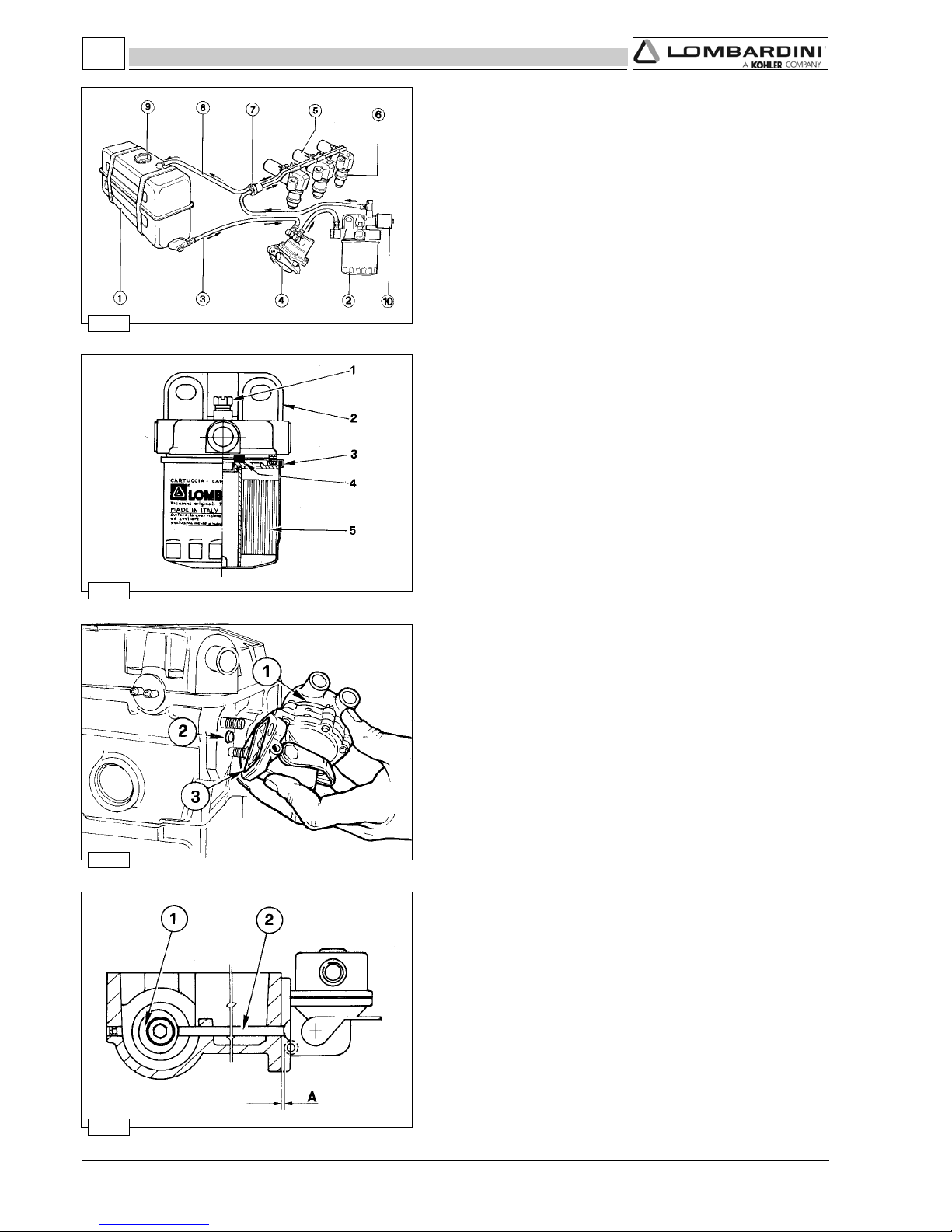
- 74 -
FOCS Workshop Manual_cod. 1.5302.351_7° ed_ rev. 06
164
165
166
167
8
Fuel feeding / injection circuit
Components: 1 Fuel Tank
2 Fuel filter
3 Fuel feeding tube
4 Fuel lift pump
5 lnjection pump
6 Injector
7 Fuel rail passage rubber joint
8 Injector exhaust pipe
9 Fuel tank cap
10 Solenoid valve
Note: The tank complete with filter is supplied on request.
Fuel pump drive rod projection
The protrusion A of drive rod 2 from the cylinder head surface is
1.66÷2.18 mm.
The check must be carried out with cam 1 idle as in the figure.
Block the two fuel pump fastening nuts simultaneously at 24 Nm.
Check the length of the drive rod and if it is not the right size,
replace it.
Drive rod length = 153.15÷153.35 mm.
Fuel lift pump
Components:
1 Fuel lift pump
2 Push rod
3 Seal ring
The fuel pump is membrane type. It is driven by camshaft cam via
a drive rod.
It is equipped with an external manual fuel lever.
Characteristics:
With the control cam at 1500 rpm the delivery rate is 75 l/hours and
the self-adjusting pressure is at 0.55 to 0.65 bar.
Fuel filter detached from the tank (on request)
1 Air relief valve
2 Bearing
3 Cartridge
4 Rubber element
5 Filtering element
Cartridge characteristics:
Filtering paper: ................................ PF 905
Filtering surface: .............................. 2400 cm
2
Degree of filtration: .......................... 2÷3
µµ
µµ
µ
Maximum operating pressure: ........ 4 bar
 See page 24 for periodic maintenance details.
FUEL SYSTEM
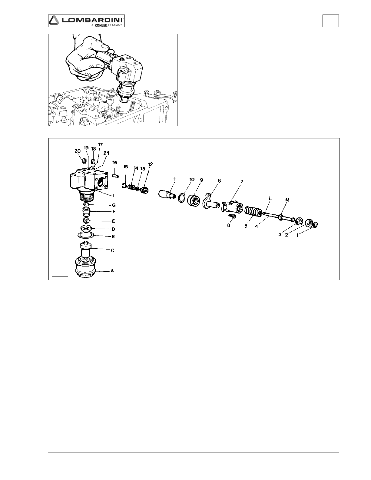
- 75 -
FOCS Workshop Manual_cod. 1.5302.351_7° ed_ rev. 06
168
169
8
Pump/injector unit
Designed by LOMBARDINI, the pump/injector is exclusive to FOCS
series engines.
The injection system includes two, three, four identical pumps/
injector units, each one of which feeds a cylinder.
Note: On pumps/injector units of recent construction (for serial
numbers and references see the table on page 78) the pump
has been modified (see fig. 174).
Following to this modification and others like the elimination
of cap 20 of fig. 169 the method of checking the static
injection advance has changed as well, fig. 187-188 as that of
injector setting, fig. 178.
Pump/injector unit, components
1 Seeger ring A Ring nut
2 Tappet B O-ring
3 Stop plate C Nozzle
4 Plunger D Spacer
5 Spring E Pressure rod
6 Screw F Spring
7 Bearing G Spacer
8 Lever I Casing
9 Ring nut L Control spiral
10 Plunger guide O-ring M Plunger guide
11 Cylinder
12 Delivery valve
13 Gasket
14 Spring
15 Filler
16 Pin When remounting the injector tighten ring nut A at 70 Nm
17 O-ring
18 Non-return valve
19 O-ring
20 Cap screw (old type)
21 Metal gasket (new type)
Fuel system

- 76 -
FOCS Workshop Manual_cod. 1.5302.351_7° ed_ rev. 06
170
171
172
8
Plunger barrel ring nut assembly/disassembly
To disassemble ring nut 9 fig. 169, use the suitable wrench A se.no.
7107-1460-029
When refitting tighten it a torque of 34 Nm.
Plunger injection pump reassembly
To be able to insert the plunger in its barrel press with a finger and
at the same time slowly rotate lever 8 fig. 171 until guide M of the
plunger fig. 172 enters the lever seating.
Note: If by mistake the plunger is mounted with the spiral in the
wrong direction the pump won’t function (there is no danger
that the engine runs away).
Injection pump assembly/disassembly
Disassemble the unit following the progressive order of fig. 169.
Reassemble following the same steps in reverse order.
During reassembly, turn the plunger spiral L towards the non-return
valve 19, as follows.
Fuel system

- 77 -
FOCS Workshop Manual_cod. 1.5302.351_7° ed_ rev. 06
8
AB C D E F
205
703.09565.5
05.1
÷
55.1
05.1
÷
35.1
569.9
÷
530.01
565.9
÷
536.9
9.0
206-205
4021-309
582.09560.6
T/4021
4041-3001-207
092.09565.6
5,9006332÷91
5,9002142÷51
00383÷53
A
5,5
B
30,2÷00,2
C
35,1÷05,1
D
00,01
E
6,9
F
7,0
173
174
175
Pumping element (old-type injection pump)
1 Plunger
2 Upper plunger section
3 Plunger barrel
4 Delay notch
5 Control slot
Dimensions (mm):
Pumping element
1 Plunger
2 Upper plunger section
3 Plunger barrel
4 Delay notch
5 Control slot
Pump/injector unit se.no. 6590.285 control data.
1 Delivery control lever on stop position.
2 Delivery control lever on maximum delivery position.
Injector setting pressure: 140÷155 bar
* Rpm rating is that of the crankshaft.
nominal value
inlet hole diameter
outlet hole diameter
Rod stroke form max delivery
position (mm)
start position
mm
3
/strokeRpm (*)
Aluminium
crankcase
INJECTION
PUMP
Dimensions
Fuel system

- 78 -
FOCS Workshop Manual_cod. 1.5302.351_7° ed_ rev. 06
231-2
272-0
235-2
272
272-1
272-
272+
235-4
235-4
235-3
235-4
6590.262
6590.283
6590.235
6590.272
6590.285
6590.286
6590.307
6590.290
6590.287
6590.290
502 - 602 - 903 - 1204
502 MINI CAR
1204/T
502 - 602 - 903 - 1204
502 - 602 - 903 - 1204
502 MINI CAR
1204/T
702 - 1003 - 1404
11° - 13°
11° - 13°
4° - 6°
8° - 10°
8° - 10° < 2999 g/min
12° - 14° > 3000 g/min
11° - 13°
6° - 8°
8° ÷ 10° < 2999 g/min
12° ÷ 14° 3000÷3600 g/min
13° ÷ 14° > 3600 g/min
8
176
Lombardini injection system is being steadily implemented, seeking the best performance of its engines.
For this reason the pump injector body has been modified three times in the course of its evolution.
Three different pump injectors are shown in the top figure.
Old type injector pump: it is characterised by its high pressure hole
Intermediate injector pump: is characterised by not having the high pressure hole (the hole can be there but it is only used
to control the injector and injection advance) and by the locating peg between inlet and outlet
holes.
Current pump injector: it is characterised by its offset inlet and outlet holes. These are also oversized, due to the
absence of the high pressure hole.
REFERENCE
N°
CODE N°
ENGINE TYPE
INJECTION
ADVANCE VALUE
SPECIAL TOOLS
LOCATING PEG
OFFSET HOLES
HIGH PREASSURE HOLE
REFERENCE NUMBER
OLD TYPE INJECTOR PUMP
INTERMEDIATE INJECTOR PUMP CURRENT PUMP INJECTOR
ADVANCE .......................... 1460.028 + 1460.024
INJECTOR SETTING ........ 1460.028
T.D.C. ................................. 1460.048
ADVANCE .......................... 1460.028 + 1460.024
INJECTOR SETTING ........ 1460.028
T.D.C. ................................. 1460.048
ADVANCE .......................... 1460.028 + 1460.024
INJECTOR SETTING ........ 1460.028
T.D.C. ................................. 1460.048
ADVANCE .......................... 1460.056
INJECTOR SETTING ........ 1460.028
T.D.C. ................................. 1460.048
ADVANCE / INJECTOR SETTING ........ 1460.074
T.D.C. ..................................................... 1460.048
ADVANCE / INJECTOR SETTING ........ 1460.074
T.D.C. ..................................................... 1460.048
ADVANCE / INJECTOR SETTING ........ 1460.074
T.D.C. ..................................................... 1460.048
ADVANCE / INJECTOR SETTING ........ 1460.074
T.D.C. ..................................................... 1460.048
Fuel system

- 79 -
FOCS Workshop Manual_cod. 1.5302.351_7° ed_ rev. 06
8
177
178
179
181
180
Injector, setting (old type)
Connect the injector to a hand pump after removing cap screw 20
fig. 169.
By means of the tool - se.no. 7107-1460-028 - check that the
setting pressure is 130÷145 bar.
Adjust, if necessary, by changing the spacer located under the
spring.
There are eleven different spare part spacers from 1 to 2 mm.
When you replace the spring, the setting should be made at a
pressure higher than 10 bar to compensate for adjustments in
operation.
Check the needle seal by slowly actuating the hand pump for 10
seconds, until you reach abt. 130 bar.
If the nozzle drips, replace it.
Injector, spark arrester
Every time you remove the pump/injector you must replace the
spark arrester, the copper gasket, the oil O-ring, as well as the 2 fuel
O-rings.
Insert the spark arrester in the injector housing with surface A
pointing upwards.
Tighten simultaneously both nuts that fasten it to the head at 20
Nm.
For engines with the injectors fixed with self-locking nuts, tighten
the nuts at 23 Nm.
 See page 24 for periodic maintenance details.
Injector, nozzle projection
To avoid excessive compression of the spark arrester A, fig. 181,
check projection B of the nozzle fig. 179.
B = 6.80÷7.05 mm.
If this measure is larger put spacer 2 between ring nut 1 and copper
gasket 3.
0.25 mm thick spacers are available.
Setting of injector according to current pump/injector unit
Remove the non-return valve leaving its metal gasket and fit a cap
screw in its place, that is part of tooling 7107-1460-074.
Mount then head 1 and coupling 2.
Then connect a hand pump as shown in the picture.
The pressure setting must be 140÷155 mm bar.
Fuel system

- 80 -
FOCS Workshop Manual_cod. 1.5302.351_7° ed_ rev. 06
ααααα
205WDL
)mm(
T/4021-4021-309-206WDL
)mm(
4041-3001-207WDL
)mm(
°81749.1763.2864.2
°71937.1511.2502.2
°61345.1678.1659.1
°51853.1156.1127.1
°41481.1044.1105.1
°31220.1242.1692.1
°21178.0950.1501.1
°11337.0198.0039.0
°01606.0737.0967.0
°9194.0795.0326.0
°8883.0274.0394.0
°7792.0263.0873.0
°6812.0662.0772.0
182
183
8
ααααα
206-205
4021-309
582-09561-2729992÷0051°01÷°8
206-205
4021-309
582-09561-2720003>°41÷°21
*205703-0956+2720063÷0003°21÷°01
3001-207
4041
092-09564-5329992÷0051°01÷°8
3001-207
4041
092-09564-5320063÷0003°41÷°21
3001-207
4041
092-09564-5320063÷>°51÷°31
T/4021092-09564-5320063÷0051°8÷°6
Injection advance control and regulation
-Dismount the rocker arm cover, see page 40.
-Position the device on the head, in contact with cylinder no. 1.
-Mount the dial gauge on the valve controlled by tool ref. 1460.048.
-Via lever 1 of the tool, open the valve until it comes into contact
with the piston.
-Then rotate the crankshaft until the TDC is read in the dial gauge.
Then reset the hundredths.
-Remove the fuel pipes.
-Remove the O-ring in contact with the non-return valve and
replace it with the appropriate gasket - equipment component part
ref. 1460.074. Once the check has been completed, remove the
gasket and refit the O-ring.
Connect tool 1460.074 on pump n° 1. This will automatically
position the control lever to the maximum delivery. The tool is
provided with 3÷4 couplings for connection to a tank that must be
not lower than 30 cm from the pumps level. Coupling 2 is
equipped with a plastic pipe with internal drip collecting wire.
-Put cylinder 1 under compression and open the tank tap. Fuel
diesel will start to flow out from coupling 2.
-Slowly rotate the engine towards TDC 1 until the diesel fuel stops
leaking out.
-At this point with lever 1 (of fig. 182) move again the valve until it
touches the piston and read on the dial gauge how many
hundredths are missing from the previously reset value (TDC).
-To convert hundredths into degrees, consult the table below.
-Repeat the operation on the other cylinders.
Injection advance for currently used pump/injector unit
* With aluminuim crankcase
Engine Code Reference n° Rpm
Fuel system

- 81 -
FOCS Workshop Manual_cod. 1.5302.351_7° ed_ rev. 06
8
184
185
186
187
Static injection advance tuning
If the injection advance value found does not correspond to the
previously described value, adjust the screw E and repeat the test.
Rotating screw E by ½ turn will change the injection advance by 5°.
If turned clockwise, injection is advanced.
In the opposite direction, injection is delayed.
Tester and special coupling for injection advance control (Oldtype injection pump)
1 Special coupling. Serial number: 7107-1460-028
2 Injection advance tester. Serial number: 7271-1460-024.
Remove the cap on the pump/injector casing and in its place screw
on coupling 1.
On this coupling tighten the tester 2.
Note: When reassembling the cap on the pump/injector unit, check
its seal.
TDC (Top Dead Center) references
D coincides with A =TDC of 1
st
cylinder of all series engines, of 4
th
cylinder LDW 1204-1204/T-1404, and of 2
nd
cylinder LDW 502.
E coincides with A =TDC of the 2nd cylinder LDW 903-1003.
F coincides with A =TDC of 2nd cylinder LDW 602-702., of 3
rd
and 2nd cylinder LDW 1204-1204/T-1404.
G coincides with A =TDC of 3rd cylinder LDW 903-1003.
Note: Following the arrow’s rotation direction, the combustion
order for LDW 903-1003 is D, G, E (1st - 3rd - 2nd cylinder
respectively. As to LDW 1204-1204/T-1404 the sequence is
D, F, D, F (1st– 3rd– 4th and 2nd cylinder).
Injection advance references on timing belt protector
The method of checking injection advance is essentially the same as
that described in fig. 182 with one difference: instead of using the
device se.no. 7107-1460-048 with which you measure piston
lowering with respect to the Top Dead Centre, you use references A
and C on the timing belt protector and reference D located on engine
pulley.
When D coincides with A the piston has reached its TDC.
When D coincides with C the piston is in injection advance position.
Fuel system

- 82 -
FOCS Workshop Manual_cod. 1.5302.351_7° ed_ rev. 06
188
189
8
190 191
Static injection advance regulation
Fill the tank and operate the fuel pump.
Set the pump/injector delivery control rod (ref. A fig. 187) at halfstroke.
Bring the piston to the top dead centre of compression. Fit a 13
mm hexagon wrench on the injection advance adjusting screw lock
nut. By turning the wrench forth and back you prime the injection
pump, thus enabling the tester to be drained.
With the piston at its TDC, operate lever 2 fig. 188 and bring the
drain valve into contact with the piston. Then reset dial gauge.
Go back ¼ of a turn moving the crankshaft anticlockwise. Then
turn forward again very slowly
observing the fuel level inside the tester. As soon as the level
changes, then stop. You reached the static injection advance.
By actuating lever 2 check piston lowering with respect to the TDC
that shall be between 0.89 and 1.24 mm for LDW 602-903-1204,
and between 0.73 and 1.02 for LDW 502 engine model.
The table on page 80 shows both piston lowering expressed in mm,
with respect to the TDC, and the corresponding rotation of the
crankshaft, expressed in degrees.
The static injection advance in degrees
αα
αα
α = 11° to 13° refers to all
engines for adjustments from 1500 / 3600 rpm.
Test head B assembly
Remove fuel pipe A and mount one test head B in its place per
pump/injector.
The test heads complete with pipes are supplied together with
instrument ref. 7104-1460-069.
Preliminary steps to pump/injector unit delivery balancing test
Closing the oilhole
To perform this test you must remove the rocker arms cover and
close hole 1 with an M 8x1.25 or M 10x1.5 screw (on latest model
engines) not longer than 8 mm. Also remove the copper gasket.
If the camshaft and rocker arms are dry, lubricate them with engine
oil.
Note: If you only want to check the nozzle it is not necessary to
balance the deliveries; provided that when you dismount the
rod you do not loosen adjusting screws 1 and 2 (fig. 193).
Fuel system

- 83 -
FOCS Workshop Manual_cod. 1.5302.351_7° ed_ rev. 06
8
192
193
Injection pumps delivery balancing
In case the balancing error read on the test pieces is greater than 2
cm³/min, then injection pumps deliveries should be adjusted.
Plate 4 and rod 3 are blocked by screws 1 and 2. Loosen them.
Move plate 4 rightwards with respect to rod 3 if you want to
increase delivery.
If moved leftwards delivery decreases. Make very small movements
with the plate.
Tighten screws 1 and 2 at a torque of 1,1 Nm.
Note: Each time a pump/injector is replaced it is necessary to
balance the deliveries.
Instrument connection
Place the instrument 1, se.no. 7104-1460-127 at least 20 cm above
the pump/injector level.
Connect pipe A (outlet from every instrument test piece) with pipe A
(inlet of every pump/injector) and pipe B (return to the instrument)
with pipe B (outlet from the pump/injector).
Open tap 2 and 3 of each pipe and fill the instrument with diesel.
Start the engine and bring it to 1500 rpm idle running.
Close the fuel supply to the engine from the instrument’s tank using
lever 4 and after 1 minute observe the levels in the test piece.
If a level goes down more than the others it is necessary to decrease
the delivery of the corresponding pump (see below) and vice versa
to increase the delivery if the level increases.
Fuel system

- 84 -
FOCS Workshop Manual_cod. 1.5302.351_7° ed_ rev. 06
4
12
2
10
7
6
5
9
9
ELECTRIC CONTROL PANEL WITH AUTOMATIC ENGINE STOP
(UPON REQUEST)
AUXILIARY TERMINALS
(+) Positive pole under key (6.3)
(-) Negative pole - Earth (6.3)
Signal for temp. water instrument (4.75)
Signal for electric rev. counter (4.75)
Oil pressure signal (4.75)
Protected socket available (4.75)
Protected socket available (4.75)
Rear connection – Jumper with 6 for alternator protection
Control panel auxiliary terminals 2, 4, 5, 6, 7, 10 and 12 are also accessible from
the front, under the fuse access door.
BLACK
BLACK
BLUE
RED
ORANGE
PURPLE
BLUE
RED
BLACK
GRAY
WHITE
GREEN
LIGHT BLUE
PINK
BROWN
PUSH-ON CONNECTION
STARTING
MOTOR
BATTERY C ONNECT ION
POST
GLOW-PLUGS
FUEL
SOLENOID
ALTERNATO R
CONNECTOR
EXCITATION TERMINAL
COOLANT
TEMP.THERMISTOR
(FOR GLOW TIMER/
RELAY)
COOLANT HIGH
TEMP. SWITCH
LOW FUEL
LEVEL SWITCH
LOW OIL PRESSURE
SWITCH
BLACK
BLACK
AIR FILTER RESTRICTION
INDICATOR
COOLANT TEMP.
SENDING UNIT
YELLOW
ELECTRIC SYSTEM

- 85 -
FOCS Workshop Manual_cod. 1.5302.351_7° ed_ rev. 06
9
194
195
Alternator, Iskra 14V 33A
Nominal voltage ................. 14V
Nominal current output ...... 33A
Maximum Rpm .................. 12.000 giri/1'
Maximum peak Rpm ......... 13.000 giri/1'
Voltage regulator AER 1503
Rotation (viewed at puley end): Clockwise
Tighten nut 1 at a torque of 35÷45 Nm.
Alternator, Iskra 14V 33A - Performance Curve
The curve was obtained at room temperature of +25°C with 13 V
battery voltage.
Note: The rpm shown on the table are referred to the alternator.
Engine rpm/alternator rpm ratio, with driving pulley diameter
88 mm = 1:1.23
Electric System

- 86 -
FOCS Workshop Manual_cod. 1.5302.351_7° ed_ rev. 06
205
2,14401266003
1,14401266003
207-206
1,14401266003
6,16600388033
3001-309
1,14401266003
6,16601388033
4041-4021
1,14401266003
6,16600388033
T/4021
1,15555266003
6,16600388033
196
9
Electric starting layout (12V) with Iskra alternator 14V 33A
1 Alternator
2 Starter Motor
3 Battery
4 Glow Plugs
5 Coolant temperature thermistor
6 Glow Plug Controller / Timer
7 Key Switch
8 System Fuse, 30A for LDW 502-602-702; 50 A for LDW 903-
1003; 80 A for LDW 1204-1204/T-1404.
9 Fuse (Accessory)- 5A
10 Fuel Solenoid Valve
11 Glow Plug Indicator Lamp
12 Coolant High Temperature Lamp
13 Coolant High Temperature Switch
14 Oil Pressure (Low) Lamp
15 Oil Pressure Switch
16 Alternator Charging Lamp
17 Air Filter High Restriction Indicator Lamp
18 Air Filter Restriction Switch
19 Low Fuel Level Lamp
20 Low Fuel Level Switch
A Accessory Position
B Off Position
C On Position
D Starting Position
Note: Battery 3 not supplied by LOMBARDINI.
For assembly we recommend a battery with the following
characteristics, see table below.
Engine type
Starter motor class
(epicyclic type) Kw
Capacity
K20 - Ah
Rapid discharge
intensity
(DIN Standards at
-18° C) A
Capacity
K20 - Ah
Rapid discharge
intensity
(DIN Standards at
-18° C) A
Normal starting conditions
Heavy-duty starting conditions
(max allowed)
Electric System

- 87 -
FOCS Workshop Manual_cod. 1.5302.351_7° ed_ rev. 06
9
197
198
Alternator, Marelli type AA 125 R 14V 45A
Characteristics:
Nominal voltage ........................................ = 14V
Nominal current output ............................. = 45A
Maximum Rpm ......................................... = 14000 giri/1'
Maximum peak Rpm (for 15') ................... = 15000 giri/1'
Bearing, Pulley End .................................. = 6203-2Z
Bearing, Voltage Regulator End ............... = 6201-2Z/C3
Voltage regulator ...................................... = RTT 119 A
Rotation (viewed at puley end): Clockwise
Note: Use only high temperature grease when servicing bearings
Tighten nut 1 at a torque of 60 Nm.
Alternator, Marelli type AA 125 R 14V 45A - Performance Curve
The curve was obtained at room temperature of +25°C with a costant
13 V battery voltage.
P1 = Power Output (KW)
I = Current Output (Amps)
ηη
ηη
η = Efficiency
Note: The RPM shown is that of the alternator. The value of the
rpm axis must be multiplied by 1000.
Alternator speed is a function of engine speed and the
crankshaft pulley diameter. If the engine pulley is 88 mm,
then the alternator speed ration is 1.3:1. If the engine pulley
is 108 mm, then the alternator speed ratio is 1.6 : 1.
Electric System

- 88 -
FOCS Workshop Manual_cod. 1.5302.351_7° ed_ rev. 06
199
200
9
Electric starting layout (12V) with Marelli type AA 125 R 14V 45A
alternator
1 Alternator
2 Starter Motor
3 Battery
4 Glow Plugs
5 Coolant temperature thermistor
6 Glow Plug Controller / Timer
7 Key Switch
8 System Fuse, 30A for LDW 502-602-702; 50 A for LDW 903-
1003; 80 A for LDW 1204-1204/T-1404.
9 Fuse (Accessory)- 5A
10 Fuel Solenoid Valve
11 Glow Plug Indicator Lamp
12 Coolant High Temperature Lamp
14 Oil Pressure (Low) Lamp
15 Oil Pressure Switch
16 Alternator Charging Lamp
17 Diode
18 Air Filter Restriction Switch
19 Air Filter Restriction Switch
20 Low Fuel Level Lamp
21 Low Fuel Level Switch
A Accessory Position
B Off Position
C On Position
D Starting Position
Note: Battery 3 not supplied by LOMBARDINI, for battery
characteristics see page 89.
Flywheel Alternator
12V 20A with three cables at output
12V 30A with two cables at output
1 Flywheel
2 Ring gear
3 Magnet ring (Rotor)
4 Stator
Electric System

- 89 -
FOCS Workshop Manual_cod. 1.5302.351_7° ed_ rev. 06
9
201
202
Alternator battery charger curve 12V 20A
(three cables at output)
This curve is obtained at 20°C.
The statistical charging output of the flywheel alternator is +10% to 5% of the values shown.
Alternator battery charger curve 12V 30A
(two cables at output)
This curve is obtained at 20°C.
The statistical charging output of the flywheel alternator is +10% to 5% of the values shown.
Electric System

- 90 -
FOCS Workshop Manual_cod. 1.5302.351_7° ed_ rev. 06
ASTEA
ASIRPAS
ASCIN
ITACUD
~G53,68,0
RR05,92,1
+B05,92,1
ELL57,45,0
C52,68,0
203
204 205
9
Electric starting layout (12V) with flywheel alternator
1 Alternator
2 Starter Motor
3 Battery
4 Glow Plugs
5 Coolant temperature thermistor
6 Glow Plug Controller / Timer
7 Key Switch
8 System Fuse, 40A
9 Fuse (Accessory)- 5A
10 Fuel Solenoid Valve
11 Glow Plug Indicator Lamp
12 Coolant High Temperature Lamp
13 Coolant High Temperature Switch
14 Oil Pressure (Low) Lamp
15 Oil Pressure Switch
16 Alternator Charging Lamp
17 Voltage regulator
18 Air Filter High Restriction Indicator Lamp
19 Air Filter Restriction Switch
20 Low Fuel Level Lamp
21 Low Fuel Level Switch
A Accessory Position
B Off Position
C On Position
D Starting Position
Note: Battery 3 not supplied by LOMBARDINI.
Cable
colour
Yellow
Red
Red
Green
Brown
Conncetion dimensions
Width Thickness
Voltage regulator connections
Electric System

- 91 -
FOCS Workshop Manual_cod. 1.5302.351_7° ed_ rev. 06
9
206
207
208
STARTER MOTOR - Bosch DW 12V 1,1 KW
Rotation: Clockwise
A = 17,5÷19,5 mm
(distance from starter mounting flange to ring gear face)
Note: Please refer to your local BOSCH distributor for service parts,
repair criterion and warranty service.
Starter motor, Bosch 12V 1,6 Kw
Rotation: Clockwise
A = 29,50÷31,5 mm
(distance from starter mounting flange to ring gear face)
Note: Please refer to your local BOSCH distributor for service parts,
repair criterion and warranty service.
Starter motor, Bosch DW 12V 1,1 KW - Performance Curve
The curve was obtained at room temperature of -20°C with a fully
charged 66Ah battery.
U =Starter Motor Voltag
n =Armature r/min
I =Absorbed Amperage
P =Starter Output Power (KW)
M =Starter Output Torque (Nm)
Electric System

- 92 -
FOCS Workshop Manual_cod. 1.5302.351_7° ed_ rev. 06
0007
0042
001
064
02-
0
02+
04+
5.92÷5.32
5.61÷5.31
5.01÷5.8
0.8÷0.6
0.7÷0.4
02305+
≤
210
212
211
9
209
Pre-heating plug control unit with coolant temperature sensor
To avoid white smoke immediately following start-up post-heat for
about 5 seconds, see table
 For electrical connections see figures 196-199-203.
Pre-heating glow plug
Characteristics:
Nominal voltage ........................................ 12,5V
Current absorption .................................... 12A÷14A after 5 seconds
Sheath surface temperature ..................... 850°C after 5 seconds.
Components:
1 Sheath
2 Primary Heating Coil
3 Secondary Heating Coil
When remounting tighten at a torque of 20 Nm.
Post-heat
Glow-plug heat time
(sec.)
Pre-heat
Coolant temp.
°C
Resistance
(ohm)
Thermistor input
Heating stop
Starter motor, Bosch DW 12V 1,6 KW - Performance Curve
The curve was obtained at room temperature of -20°C with a fully
charged 88 Ah battery.
U =Starter Motor Voltag
n =Armature r/min
I =Absorbed Amperage
P =Starter Output Power (KW)
M =Starter Output Torque (Nm)
Electric System

- 93 -
FOCS Workshop Manual_cod. 1.5302.351_7° ed_ rev. 06
213
215
214
216
9
Oil pressure switch (Fig. 215)
Characteristics:
Opening pressure: 0,15÷0,45 bar (for gen-sets: 1,4 bar).
Tightening torque 25 Nm.
Coolant high temperature lamp sensor (Fig. 216)
Characteristics:
Circuit ............................................. single pole
Voltage range ................................. 6÷24 V
Max. Power Absorption.................. 3 W
Closing temperature ...................... 107÷113°C
Tightening torque 25 Nm.
Temperature sensor for control unit
In engines fitted with the above-mentioned type of control unit, the
introduction of the glow plugs depends on a temperature sensor that
varies preheating temperature in relation to the coolant temperature.
Characteristics:
Temperature range ............... -30 ÷ +50°C
Voltage range ........................ 6÷24 V
Temperature max. ................ 150°C
Max. tightening torque. ......... 30 Nm.
Electric System

- 94 -
FOCS Workshop Manual_cod. 1.5302.351_7° ed_ rev. 06
217
218
10
219
SPEED SETTINGS
Setting the idle minimum (standard)
After filling the engine with oil, fuel and coolant, start it and let it
warm up for 10 minutes.
Turn the screw 1 to adjust the idle speed at 850 to 900 rpm.
Tighten then the locknut.
Note: If you loosen screw 1 speed decreases. To the opposite
direction speed increases.
Setting the idle maximum (standard)
After setting the idle speed turn screw 2 and regulate the idle
maximum at 3800 rpm.
Block then the locknut.
When the engine reaches its setting power, the maximum rpm will
stabilise at 3600 rpm.
Note: If you loosen screw 2 speed increases.
To the opposite direction speed decreases.
Pump injection delivery standard setting without
dynamometric brake
This adjustment must be performed with the dynamometric braked
engine.
Without this the regulation is approximate.
In this case proceed as follows:
-Unlock the maximum flow limiter lock nut.
-Fully screw in flow limiter C.
-Run the engine to the maximum speed, that is 3800 rpm.
-Loosen flow limiter C until the engine revs start to decrease.
-Screw flow limiter C by 2.5 turns.
-Tighten the lock nut.
Note: If the engine under maximum load emits too much smoke
unscrew C. Tighten C if at this load there is no smoke and if
the engine does not reach its maximum power.
SETTINGS

- 95 -
FOCS Workshop Manual_cod. 1.5302.351_7° ed_ rev. 06
220 221
222
223
10
Setting the stop
Remove the rocker arms cover and completely unloosen screw B.
Push rod A to the right and keep it in this position; see figure.
Tighten screw B until it touches rod A.
Release rod A and tighten again screw B by a 0.5÷1.0 turn.
Tighten the lock nut.
Pump/injector unit timing with speed governor
-Loosen the screws C of each pump/injector unit.
-If it is not connected, connect spring D to rod A (with this
operation the speed governor blocks are closed).
-Move plates B of each pump/injector unit rightwards; see figure
(with this operation the pumps/injector unit are at their maximum
delivery).
-Tighten screws C at 1.1 Nm. Re-balance the deliveries.
Note: Spring D is the start-up fuel supplement spring: with the
engine stopped pull rod A to the right by bringing the pump/
injector unit delivery to the maximum value, until the speed
governor comes into operation with the engine running
Injection pump flow limiter and engine torque gearing device
Flow limiter C has the function of limiting the injection pump’s
maximum delivery.
The same mechanism acts also as a torque gearing device.
Indeed, under torque, spring N operating lever L overcomes the
resistance of spring M located in the plunger barrel.
The stroke H that the torque gearing device allows to be carried out
by lever L, will increase the injection pump delivery and the torque
will hit its maximum value.
Important
The stroke H varies depending on which engine torque gearing
device is fitted on the engine.
Settings

- 96 -
FOCS Workshop Manual_cod. 1.5302.351_7° ed_ rev. 06
wKhwK/g
205
002215,5381÷291992÷582
006327,7511÷021043÷623
206
002253,7741÷551972÷562
006329,998÷39043÷623
309
002280,1199÷501472÷162
006360,5185÷06243÷823
4021
002287,4157÷97272÷852
006322,0244÷8,54043÷623
T/4021006305,9253÷63092÷482
224
10
Pump/injector unit delivery setting with braked engine
1)Run the engine to the maximum speed.
2) Screw flow limiter C (see fig. 219).
3) Load the engine up to the power and number of revs required by
the application’s manufacturer.
4) Check that consumption is within the values allowed for in the
settings table (see below).
If consumption is not within the given figures, it is necessary to
change the balance conditions shown to the brake, altering the
load and the speed governor. Redo the consumption check on the
stabilised engine.
5) Unscrew limiter C until the engine rpm start to decrease. Lock the
limiter using the lock nut.
6) Completely release the brake and check the rpm at which the
engine stabilises.
The performance of the speed governor must meet the class
required by the application’s manufacturer.
7) Stop the engine.
8) Recheck the valve clearance with the engine cold.
Specific fuel consumption
Time (sec) per
100 cm
3
Power*
( NB curve )
RpmEngine
Required settings (as most commonly applies)
* Refers to power curve NB, see pages 18÷20 and after run-in.
Settings

- 97 -
FOCS Workshop Manual_cod. 1.5302.351_7° ed_ rev. 06
225
10
E.G.R. calibration
Mount a T-branch on vacuum valve - E.G.R. valve connection pipe
(1), and connect it to a vacuum pressure gauge with 1 bar bottom
scale so as to be able to read the degree of vacuum within the pipe.
Note: It is also possible to use a mercury column, 1 metre long,
since the maximum suction pressure exerted by the vacuum
pump is 720 mmHg.
Adjust the position of the accelerator lever via the regulator block, so
that the internal adjusting nut (2), is about 5 mm from the end of the
thread.
Accelerate the engine up to 3.600 rpm (with valve closed: this
means that the value showed on the vacuum pressure gauge or on
the mercury column should be 0.
In case it is different from zero, adjust the regulator block nuts to
move it, in relation to the rod (3), in the direction that goes from the
flywheel to the timing.
With the brake at a braking curve N=constant, “load” the engine
slowing it down to 2.800 rpm.
Acting on the accelerator look for the E.G.R. valve closing point
(pressure of the vacuum pressure gauge or mercury gauge equal to
zero).
Note: Pay attention to determine the precise closing point: by
slightly accelerating the engine the vacuum value in the
E.G.R. operation pipe should immediately increase.
Measure the engine consumption in order to calculate the mm3/
stroke value.
If the calculated value is less than 18.8 mm3/stroke, adjust the
adjusting nut making it closer to the end of the rod (3) to “increase
the calibration”.
When the required value of 18.8 mm3/stroke has been reached (and
a power of around 7 KW) tighten the adjusting nuts.
Settings

- 98 -
FOCS Workshop Manual_cod. 1.5302.351_7° ed_ rev. 06
11
- If the engine is not to be used for long periods, check the storage environment, the type of packaging and make sure these
conditions will allow proper maintenance. If necessary, cover the engine with protective sheeting.
-Do not store the engine directly on the ground, in damp environments, in areas exposed to the elements, near sources of
danger, including less visible hazards such as high-voltage power lines, etc.
Caution - Warning
If the engine is not to be used for more than 1 month, it is necessary to apply protective measures that are valid for 6
months (see “Protective treatment”).
Important
If, after the first 6 months, the engine is still not to be used, it is necessary to carry out further measures to extend the
protection period (see “Protective treatment”).
1 -Check that the engine oil and coolant are up to level.
2 -Fill up with fuel containing 10% AGIP RUSTIA NT
3 -Run the engine at minimum idle speed for 15 minutes.
4 -Switch off the engine.
5 -Remove the lubrication oil.
6 -Fill the sump with protective oil: AGIP RUSTIA C.
7 -Start the engine and check for fuel and oil leaks.
8 -Bring the engine to ¾ of the maximum speed for 5-10 minutes.
9 -Switch off the engine.
10 -Empty the fuel tank completely.
11 -Spray SAE 10W oil on the exhaust and intake manifolds.
12 -Close all openings to prevent foreign bodies from entering.
13 -Thoroughly clean all external parts of the engine using suitable products.
14 -Treat non-painted parts with protective products (AGIP RUSTIA 100/F).
15 -Loosen the alternator/fan belt.
16 -If necessary, cover the engine with protective sheeting.
Caution - Warning
In countries in which AGIP products are not available, find an equivalent product.
AGIP RUSTIA NT: MIL-L-21260 P10, grade 2
AGIP RUSTIA C: MIL-L-644-P9
AGIP RUSTIA 100/F: MIL-C-16173D.
Important
After a year of engine inactivity, the coolant loses its properties and must be replaced.
ENGINE STORAGE (NOT INSTALLED)
PROTECTIVE TREATMENT
STORAGE

- 99 -
FOCS Workshop Manual_cod. 1.5302.351_7° ed_ rev. 06
11
PREPARING THE ENGINE FOR OPERATION AFTER PROTECTIVE TREATMENT
After a period of inactivity and before installing and running the engine, it is necessary to carry out a few measures in order to
ensure that it runs at maximum efficiency.
1 -Remove the protective sheeting.
2 -Eliminate any blockages in the exhaust and intake ducts.
3 -Use a cloth soaked in degreasing product to remove the external protective treatment.
4 -Remove the intake manifold.
5 -Inject lubrication oil (no more than 2 cm
3
) into the valves and install the intake manifold.
6 -Adjust the alternator/fan belt tension.
7 -Turn the flywheel manually to check the movement of the mechanical parts.
8 -Refill the tank with fresh fuel.
9 -Start the engine and run at ¾ of the maximum speed for 5-10 minutes.
10 -Switch off the engine.
11 -Remove the protective oil to replace with engine oil.
12 -Introduce new oil (see “Lubricants”) up to the correct level marked on the dipstick.
13 -Replace the filters (air, oil, fuel) with original spare parts.
14 -Empty the cooling circuit completely and pour in the new coolant up to the correct level.
Caution - Warning
Over time, a number of engine components and lubricants lose their properties, even when the engine is not in use,
and so it is important to consider whether they need replacing, based not only on the mileage, but also on age and wear.
15 -Install the engine and make the necessary connections and unions.
16 -Make sure that electrical contacts are intact and efficient.
17 -Check that the engine oil and coolant are up to level.
18 -Start the engine and keep at minimum speed for a few minutes.
19 -Check for leaks and, if necessary, find and eliminate the cause.
20 -Switch off the engine.
21 -Double check that the engine oil and coolant are up to level.
Storage

- 100 -
FOCS Workshop Manual_cod. 1.5302.351_7° ed_ rev. 06
1,1
40
12
20
15
10
9
60
10
10
5
24
40
8
20*
40
80
12
**
50
15
7
360
80
25
40
***
4
80
M 3 spec.
8x1
8x1,25
12x1,25
20X1,5
6
6x1
M 10
M 6
M 6
5x0,8
8x1,5
M 10
8x1,25
M 8
M 10
10x1,25
M 6
30x1,5
10x1,25
10
12x1,5
6x1
16x1,5 sin.
10x1,25
12x1,5
12x1,5
18
TCEI 4x1,5
10x1,5
62÷63 - p. 44
116 - p. 58
131÷132 - p. 61
210÷211 - p. 92
55 - p. 43
126÷130 - p. 60
97÷98 - p. 52
50 - p. 41
167 - p. 74
39 - p. 38
181 - p. 79
68 - p. 45
146 - p. 65
90÷96 - p. 51
13÷14 - p. 32
22÷24 - p. 34
34 - p. 37
215 - p. 93
152÷153 - p. 69
113÷115 - p. 57
64- p. 44
21 - p. 34
270
270
638
Silicon
7091
270
242
242
12
TORQUE SPECIFICATIONS AND USE OF SEALANT
Table of tightening torques for the main components
POSITION
Torque
( Nm )
Diam. & pitch
( mm )
Riference
(figure and page n°)
Sealant
Injection pump control rod
Connecting rod ****
Union for the nozzle (LDW 1204/T)
Glow-plugs
Oil filter cartridge (M 20x1,5 union)
Camshaft bearing (M 6 screws)
Rocker arm cover
Main bearing caps
Oil pan
Camshaft bearing support screw
Glow-plug cable nuts
Fuel lift pump nuts
Belt tensioner nut
External Stop control lever nut
Pump/injector unit fixing nut
Rocker arm assembly support nut
Fuel pump cam
Flywheel side oil seal ring flange
Pre-combustion chamber ring nut
Vacuum pump fixing screws
Belt tensioner
Crankcase
Speed governor lever screw
Driving pulley
Camshaft timing pulley
Oil pressure switch
Oil drain plug
Cylinder headù
Injection pipe
Flywheel
*Tighten the two nuts that fasten each pump/injector unit at the same time. For engines with the injectors fixed with self-
locking nuts, tighten the nuts at 23 Nm.
** Tighten these in two phases: the first phase at 100 Nm, the second phase at 180 Nm. See page 51, figures 95-96.
*** See page 57
**** Aluminium connecting rod with 35 Nm tightening torque.
 Loading...