

Page 1
LogTag Recorders Ltd
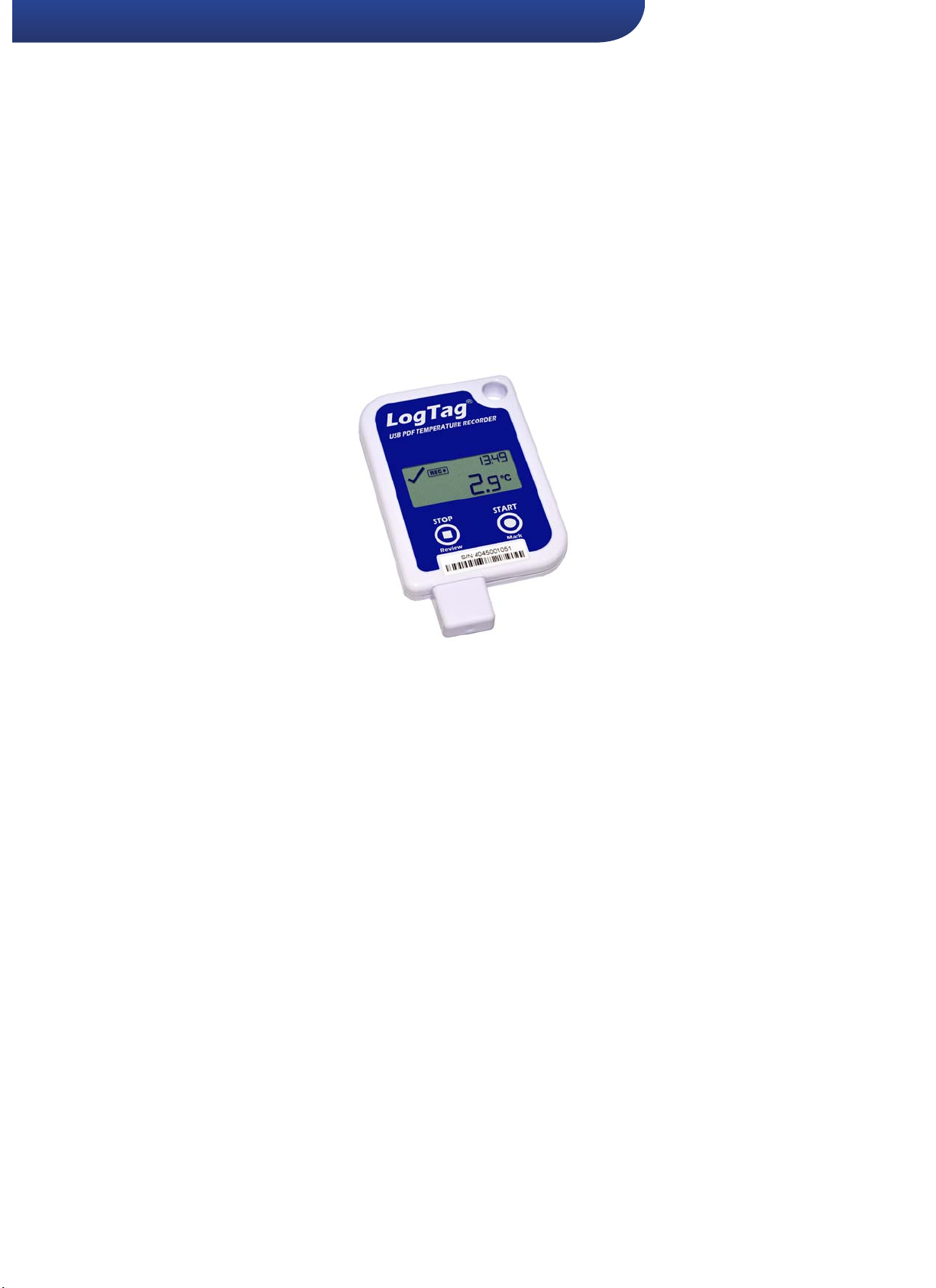
USB PDF Temperature Recorder with
UTRID-16
Display
Product User Guide
Document Release Version:1
Published 1 May 2016
Copyright © 2004-2016, LogTag®Recorders
Find Quality Products Online at: [email protected]
www.GlobalTestSupply.com
Page 2

Contents
Contents 2
Revision History 2
Safety Information 3
Liability 3
Useful Life 3
Disclaimer 3
Typographical Conventions 3
Introduction 4
Checklist - Required Equipment 4
Features 4
Case 4
Buttons 4
Display 4
Software Requirements 4
Configuring the UTRID-16 4
Standard Configuration Options 5
File Configuration Options 5
Advanced Configuration Options 5
Alarm Configuration Options 6
Finalising the configuration 6
UTRID-16 Start Options 7
Display Overview 8
Operating the Recorder 9
Configuring the Recorder 9
Starting the Recorder 9
During Recording 10
Stopping the UTRID-16 11
Reviewing Alarms 12
Plugging the UTRID-16 into a USB port 13
Accessing the files 14
Interpreting the Data 15
Data Evaluation - Report with multiple alarms 15
Data Evaluation - Data List 17
Tips and Tricks 17
UTRID-16 Factory Presets 18
Technical Specifications 21
Appendix 1 - Battery Replacement i
Revision History
Version Date Author Details
1.0 1 Sept 2016 Stefan Lenz Initial release.
Find Quality Products Online at: [email protected]
Page 2 o f 21 UTRID-16 Pro duct User Gui de, Revisio n 1, copyright © 2004- 2016, Lo gTag®Recorders . All rig hts reserved.
www.GlobalTestSupply.com
Page 3

Safety Information
The UTRID-16 PDF USB temperature recorder contains a user-replaceable Lithium Battery. When the
battery indicates “LOW”, you can replace it acc ording to the instructions in Appendix 1 - Battery
Replacement on pagei. The empty battery should be recycled or disposed of according to your local
regulations.
Do not expose the recorder to extreme temperatures as it may lead to the destruction of the battery and
may cause injuries.
Keep out of the reach of children.
Liability
LogTag®Recorders ’ standard warranty terms apply. A copy can be requested by e In addition LogTag
Recorders shall not be held liable:
l
If the device was used beyond LogTag®Recorders ’ stated limitations.
l
For any claims due to the improper storage and use of the device.
l
For any problems with refrigeration units.
l
For the bad quality of the monitored goods, if any.
l
For incorrect readings if the device was used with a low battery.
l
For consequential loss.
Useful Life
The operational life of the UTRID-16 is approx. 12 months after configuration, provided...
... the device was not stored for over 2 years12 months prior to activation,
... the device is not downloaded excessively (more than once a week),
... The recording interval is not shorter than 5 minutes,
... the device is stored and operated according to LogTag®Recorders ’ recommendations.
®
Disclaimer
The UTRID-16 monitors temperature exposure and not the quality of t he goods it accompanies. Its purpose is to signal if product quality
evaluation/testing is required.
Typographical Conventions
Text in this font refers to buttons on the UTRID-16.
Text in this font refers to option settings, dialogue boxes or actions to be taken in LogTag®Analyzer.
Text in this font describes features of the product.
Find Quality Products Online at: [email protected]
Page 3 o f 21 UTRID-16 Pro duct User Gui de, Revision 1, copyright © 2004- 2016, Lo gTag®Recorders . All rig hts reserved.
www.GlobalTestSupply.com
Page 4
Introduction
LogTag’s UTRID-16 is a fully configurable, multi-use USB PDF
temperature recorder with a built-in display, that can create
temperature reports without the need t o install proprietary software
or hardware at the destination. Select statistical data can be reviewed
directly on the display without the need for a PC. The recorder can be
configured using LogTag®Analyzer, and is t hen placed with the
goods to be monitored. At the destination the UTRID-16 can be
plugged straight into a computer’s USB port and generates a PDF file,
which can be accessed using PDF software such as Acrobat Reader.
Checklist - Required Equipment
l LogTag
l A computer running Windows XP or later, Mac OSX or Linux.
l For configuration - a PC running Windows XP SP3 or later and
®
UTRID-16 temperature recorder. It is recommended that
you connect each USB PDF Temperature Recorder with Display
via a permanently plugged in USB extension cable t o protect your
computer’s USB socket.
LogTag®Analyzer installed.
Features
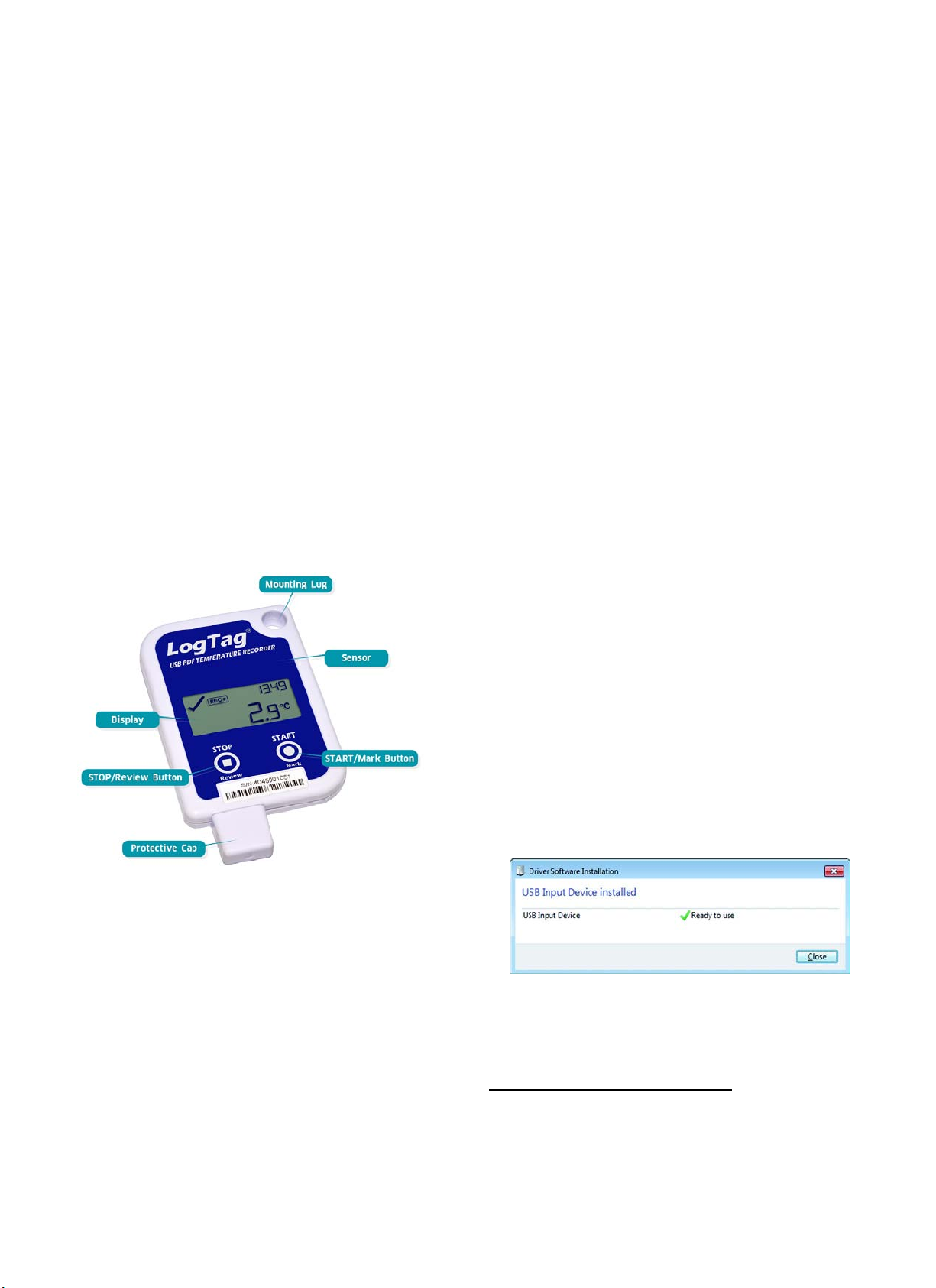
The UTRID-16 USB PDF temperature recorder features the familiar
LogTag case layout with an additional USB plug at the bottom.
Display
l Shows last recorded temperature and information about alerts
l Allows reviewing statistical data
Software Requirements
Software requirements vary depending on the type of file you want
the UTRID-16 to generate when plugged into a USB port.
l If you wish to configure UTRID-16 products you will need to
download the LogTag®Analyzer software from LogTag®’s web
site at http://www.logtagrecorders.com/software/download.php.
Follow the instruction t o install and start the software.
l
If you only plan on evaluating data, plug the UTRID-16 into a
computer‘s USB socket. Depending on the settings made during
configuration, a number of files will be generated1and made
available to you in a new drive:
o
A PDF file; you can open the file directly from the recorder‘s
USB memory storage with Acrobat Reader 4.0 or later, or any
other compatible PDF reader software of your choice.
o
A CSV file; this file can be imported into a spreadsheet
program such as Microsoft Excel.
o
An LTD file; LTD files are LogTag®Analyzer's native,
encrypted data files. You can open this file in LogTag
Analyzer, where you can analyze data in detail and generate
report files. Here, you can also combine charts from multiple
recorders for comparison.
l You can also download data directly into LogTag
without accessing the recorder‘s USB memory storage.
®
Analyzer
®
Case
l Mounting lug for secure fastening of recorder to fixtures
l USB plug with potective cap - shields USB connector from
moisture and dirt
l Temperature sensor located inside case
l Durable polycarbonate case, IP64
Buttons
l
START/Mark button; can be used to start the unit or place an
inspection mark in the data listing
l
STOP/Review button; can be used to stop the unit and to
review data recorded during the t rip.
Configuring the UTRID-16
UTRID-16 products can be ordered pre-configured, ready to start.
Different profiles are available; if none of these suit or the UTRID-16
needs different configuration settings to those already installed, the
unit can be configured using LogTag®Analyzer.
l
Start the LogTag®Analyzer software.
l
Remove the protective cap and insert the UTRID-16 into a USB
port. You will receive a message that a new USB device has been
found, and a generic driver will be installed2.
l
Once the driver is installed and the UTRID-16 is ready (indicated
by the letters USB blinking on t he display), it can receive
configuration data. Click LogTag - Configure; LogTag®Analyzer
will scan all USB ports and display the configuration options for
connected UTRID-16‘s. A lthough you can configure many devices
1
Depending on the conf iguration, the UTRID-16 may produce all, some or none of
the files.
2
Depending on the fac tory c onfiguration add itional d riversmay be installed at th is
time.
Find Quality Products Online at: [email protected]
Page 4 o f 21 UTRID-16 Pro duct User Guid e, Revisio n 1, copyright © 2004- 2016, Lo gTag®Recorders . All rig hts reserved.
www.GlobalTestSupply.com
Page 5
at the same time, it is practical to limit the number of devices to
about 10, using a powered USB hub. It is not possible to configure
different models at the same time.
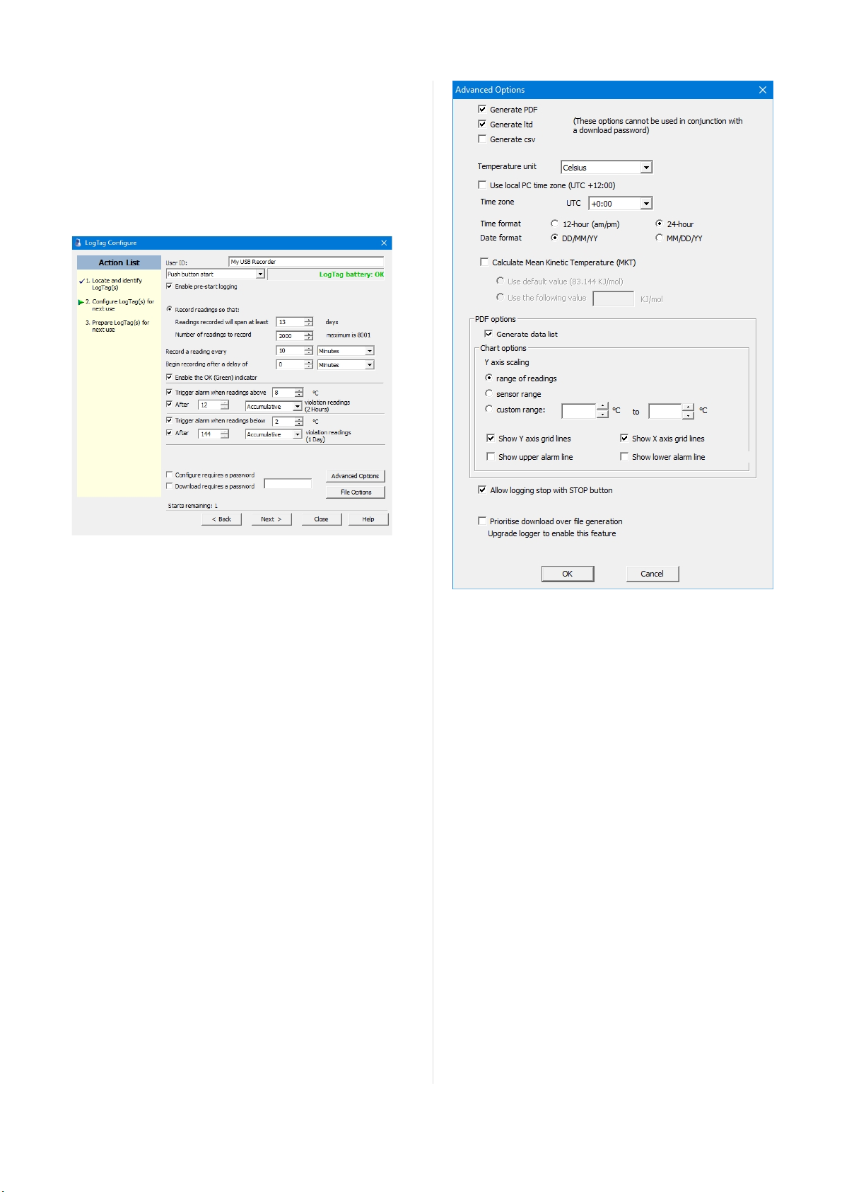
Standard Configuration Options
The standard configuration options are very similar to those of other
LogTag®recorder products and include settings such as User ID,
start method, pre-start recording, logging interval and duration,
start delay, temperature alarm parameters and password.
Figure 1: UTRID-16 S tand ard Configuration Options
For detailed information about each parameter please read the section
about Configuring a LogTag®for logging in LogTag®Analyzer’s
User Guide or press F1 for help.
File Configuration Options
Ckick File Options for additional configuration settings. These
settings decide which files -if any- are generated at the end of t he trip
and also determine the appearance and contents of the generated
files.
Figure 2: U TRID-16 advanced configuration screen
Parameters that influence t he appearance of all files are
l setting of the temperature units used in the files
l date and time format
l Time zone and MKT values
Parameters specifically influencing the appearance of the PDF file are
l scaling parameters for the chart
l showing or hiding gridlines
l showing or hiding alarm threshold lines
l creation of t he data list
You can also set whether or not the recorder can be stopped using the
STOP/Review button, and if the communication with LogTag
®
Analyzer should be prioritised over the generation of files when the
unit is plugged into a computer.
Enter the desired options and click Close to accept t he new values.
This returns you to the standard configuration dialogue.
Advanced Configuration Options
Select Advanced Options for additional display configuration
settings. These settings determine how some of the elements are
displayed on the screen and set certain options specific to the UTRID-
16.
Find Quality Products Online at: [email protected]
Page 5 of 21 UTRID-16 Product User Guide, Revisio n 1, copyright © 2004- 2016, Lo gTag®Recorders . All rig hts reserved.
www.GlobalTestSupply.com
Page 6
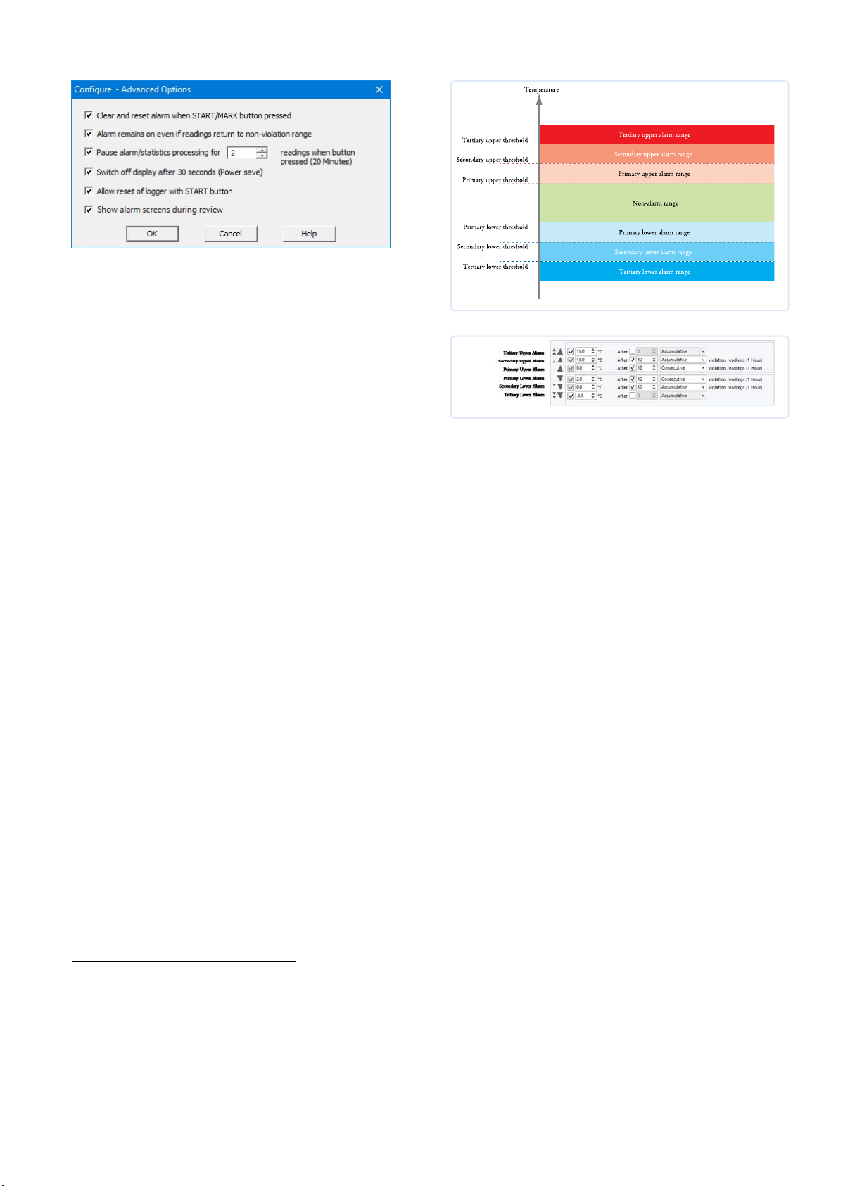
Figure 3: U TRID-16 advanced configuration screen
Parameters that influence t he appearance of the display are
l Pause alarm/statistics processing (see Paused Readings on page1)
l Switch off display after 30 seconds (Power save, see Power Save
on page1)
l showing the alarm screens during review (Reviewing Day
Statistics on the UTRID-16 on page1)
Parameters influencing specific behaviour of the UTRID-16 are
l
clear and reset alarm when the START/Mark button is pressed
l leaving the alarm turned on, even if readings return to the normal
temperature range again
l
allowing the user to reset the recorder with the START/Mark
butt on
Enter the desired options and click OK to accept the new values. This
returns you to the standard configuration dialogue.
Alarm Configuration Options
LogTag®Analyzer allows up to 6 different alarm trigger conditions
when configuring a UTRID-16 for recording, depending on the model.
Each alarm t rigger condition consists of a threshold temperature
value, an activation type (which can be instant, consecutive or
accumulative3) and a delay time, if it is not an instant alarm.
If an alarm trigger condition requires readings to exceed an upper
threshold temperature it is called an upper alarm. If an alarm trigger
condition requires readings to go below lower thresholds it is called a
lower alarm.
An alarm event is generated, when either of the entered alarm
conditions is triggered.
The UTRID-16 can have up to three upper alarms, and up to three
lower alarms.
Figure 4: Alarm ranges and thresholds
Figure 5: Represen tation in LogTag®Analyzer
You need to observe some basic rules when entering alarm conditions
into t he configuration screen in LogTag®Analyzer:
l A primary alarm condition must be entered before the
corresponding secondary alarm condition.
l Equally, primary and secondary alarm conditions must be entered
before the corresponding tertiary alarm condition.
l You can enter a different number of upper and lower conditions,
or only upper, or only lower conditions, or none at all.
l A secondary upper alarm cannot be entered with a lower
threshold value than the primary upper alarm.
l A tertiary upper alarm cannot be entered with a lower threshold
value than the secondary alarm. Threshold values can, however,
be equal and combined with different time-to-activation values.
For example, you can enter a primary upper alarm with 8°C
threshold and 10 accumulative readings, plus an alarm with 8°C
threshold and 5 consecutive readings. In this instance the alam
will be triggered, if either 10 readings in total are above 8°C, or 5
consecutive readings above 8°C have occurred.
Any alarm condition that is activated will be shown on the PDF, in
the software and on the display.
The sections about Recorders with Mult iple Alarms on page1 and
Reviewing Alarms on page12 show examples of how t his is
represented and reviewed on the display.
Finalising the configuration
l
Click Next to upload the c onfiguration data to the UTRID-16.
l
When the configuration is complete, unplug the UTRID-16 from
the USB socket and replace the protective cap.
If you wish to configure more UTRID-16 units with the same
configuration, insert the next recorder into t he USB socket, wait until
it is ready for configuration and click Again. Alternatively you can use
the Profile function to configure multiple units with the same
3
Instant = one temperature reading is above (below) the threshold
l
Consecutive = temperature readings are above (below) the threshold f or the
l
time defined in the activation delay without interruption
Accu mulative = temp erature readings are above (below) the threshold for the
l
total time define d in the ac tivation delay time, but may not necessarily be
sequential.
Find Quality Products Online at: [email protected]
Page 6 o f 21 UTRID-16 Pro duct User Guid e, Revisio n 1, copyright © 2004- 2016, Lo gTag®Recorders . All rig hts reserved.
www.GlobalTestSupply.com
settings.
You can upload t he configuration to a UTRID-16 recorder as often as
required.
Page 7

UTRID-16 Start Options
During configuration with LogTag®Analyzer you can decide when
the UTRID-16 starts taking t emperature readings.
l ... via Push button start: The recorder will start taking
temperature readings after you have gone through a specific start
sequence of pressing and releasing the START/Mark button (see
Starting the Recorder on page1).
l ... via Date/Time start : The recorder will start taking
temperature readings at the date and t ime you specify (local
time).
When you choose the push button start option, you can select to
record pre-start readings or Begin recording after a delay.
l If you select pre-start readings, the UTRID-16 starts recording as
soon as it is unplugged from the USB port4and will continue to do
so until you start the unit. No alarms are processed while prestart readings are being taken, pre-start readings will not appear
in the PDF file, and no PDF file will be generated. Using pre-start
readings is a good way do avoid data loss if you forget to start the
unit, as you can stillaccess the data using LogTag®Analyzer.
l If you configure the UTRID-16 to start after a delay period, the
recorder will not immediately record temperature readings after
you have pressed START/Mark, but start a countdown timer
instead, and record readings only after the timer has ended. It
will, however, continue t o take pre-start readings, if enabled.
You cannot combine a date/time start with pre-start readings or t he
start delay function.
4
The first p re-start read ing is taken one log interval after you unplu g the unit f rom
the USB port.
Find Quality Products Online at: [email protected]
Page 7 of 21 UTRID-16 Pro duct User Gui de, Revisio n 1, copyright © 2004- 2016, Lo gTag®Recorders . All rig hts reserved.
www.GlobalTestSupply.com
Page 8
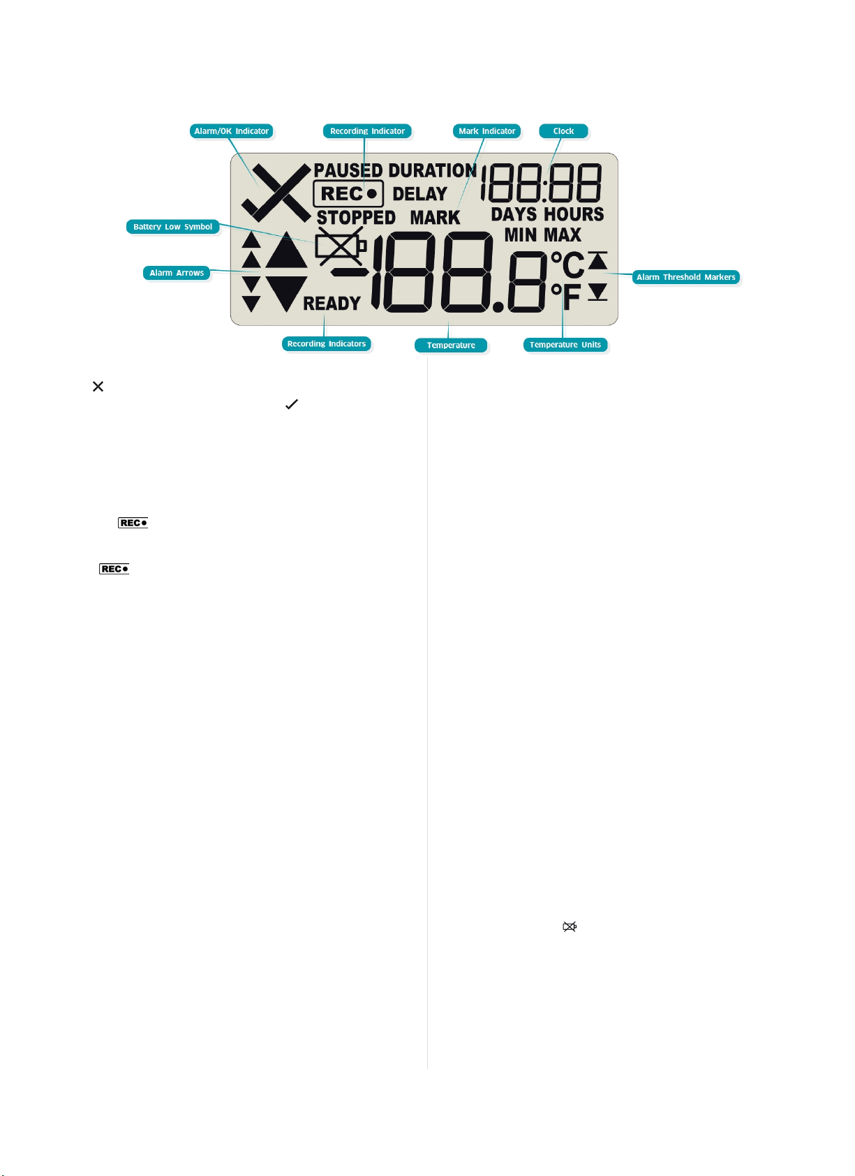
Display Overview
ALERT/OK indicator
The symbol is shown as soon as the UTRID-16 has registered an
alarm event. While there are no alarms, the symbol is shown.
Recording indicators
The recording indicators show what data the UTRID-16 is currently
collecting.
l
If the word READY is shown, the UTRID-16 is ready to be
started. Depending on the configuration it may record pre-start
readings.
l
If the symbol is shown, the UTRID-16 is recording
temperatures at the sample interval defined during configuration
with LogTag®Analyzer.
l
If is shown together with the word PAUSED, the product
is also recording, but the recorded values are not taken into
account when calculating alarm events and durations.
If the word STOPPED is shown, the UTRID-16 has finished
recording temperature data.
Mark indicator
The word MARK is shown when the next temperature reading is
identified with an inspection mark in the recorded data.
Clock
The clock display is used to show either
l
current time,
l
time remaining to start of a delayed start or
l
duration, for example of an alarm.
The display identifies which of t hose is displayed as follows:
l
If the word DELAY is shown, the time value represents a start
delay, or the time remaining until a date/time start will occur.
l
If the word DURATION is shown, the time value represents the
duration, for example the time above the upper alarm limit.
l
If the word DAYS is shown, the clock represents the number of
days in a delay or duration.
l
If the word HOURS is shown, the clock represents the number
of hours and minutes in a delay or duration. If none of the above 4
words are displayed, the clock shows the current time.
The word boo tappears in place of a clock, if new firmware is being
uploaded to the UTRID-16.
The word USb appears when the unit is plugged into a USB port.
MIN/MAX indicator
The word MAX is shown when the temperature on the display
represents t he maximum recorded temperature for the current trip.
The word MIN is shown when the t emperature on the display
represents t he minumum recorded temperature for the current trip.
Alarm Threshold Markers
The upper alarm threshold marker is shown if an alarm event
occurred at one of the upper temperature limits. It is also shown
when one of t he upper thrershold values is shown on the review
screen.
The lower alarm threshold marker is shown if an alarm event
occurred at one of the lower temperature limits. It is also shown when
one of the lower threshold values is shown on the review screen.
Temperature Units
Depending on the selected PDF temperature units, this shows either
°F or °C.
Temperature Value
This 4 character, 7-segment display shows the last recorded
temperature while the UTRID-16 is recording readings. Once the
recorder has stopped, nothing will be displayed.
Alarm Arrows
The up-arrow is shown when the temperature displayed is above the
specified upper temperature limit. The down-arrow is shown when
the temperature displayed is below the specified lower temperature
limit.
The four smaller up/down-arrows are secondary and tertiary alarm
symbols. They are used when more than one upper or more than one
lower alarm is defined and are shown then the current temperature is
above or below the corresponding alarm levels.
Battery Low
The battery low symbol will appear if the UTRID-16 has a low
battery. If the symbol is not shown while the display is turned on, the
battery is still OK.
Find Quality Products Online at: [email protected]
Page 8 o f 2 1 UTRID-16 Pro duct User Gui de, Revision 1, copyright © 2004- 2016, Lo gTag®Recorders . All rig hts reserved.
www.GlobalTestSupply.com
Page 9
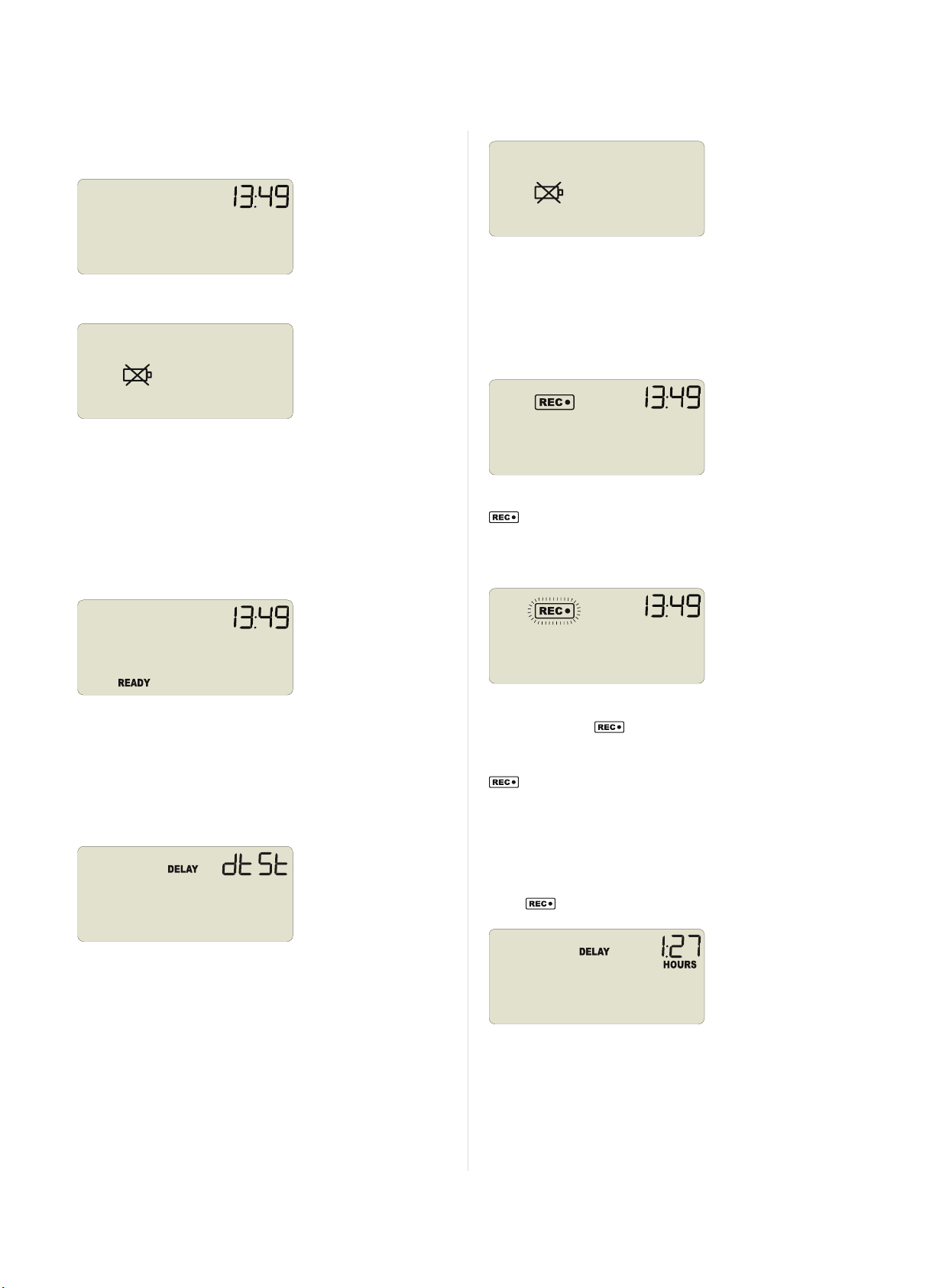
Operating the Recorder
You will receive your UTRID-16 hibernated, i.e. in a state of low
power consumption. Pressing either button will briefly show the time:
Should the battery be low, the display will show:
The following sections show how to operate the product, and what
information you can expect to see on the display.
The recorder cannot be started until the battery has been replaced.
Please see "Appendix 1 - Battery Replacement" on pagei for further
details.
Starting the Recorder
Push button start, quickstart enabled
Configuring the Recorder
Push Button Start
After configuration with LogTag®Analyzer for push button start the
word READY is shown, together with the current time in 24 hour
format.
Optionally you c an configure the unit with a start delay, and pre-start
readings. These opotions are not shown on the display.
Date and Time Start
The recorder can also be configured to start at a specific time and
date. You will see the word DELAY and the letters dt St instead of
the clock.
Press the START/Mark button until READY disappears and the
symbol is shown. The UTRID-16 now records temperature data.
This start option works the same as in LogTag®'s LED products.
Push button start, quickstart disabled
Press and hold the START/Mark button. READY immediately
disappears, and the symbol blinks for 4 seconds. The symbol
then shows permanently for 2 seconds. If you release the butt on
during this time, the recorder starts taking temperature readings. The
symbol remains shown. If t he button is released earlier than 4
seconds or later than 6 seconds, the display shows READY again, and
the recorder does not start.
Push Button Start with Start Delay
If the recorder was configured for push button start with a start delay
(regardless of quickstart settings), the word DELAY is shown instead
of the symbol.
Pre-start readings and start delay options are not available for a
date/time start.
Low Battery
If the recorder has a low battery after configuration, the low battery
symbol is shown instead of the time.
Find Quality Products Online at: [email protected]
Page 9 o f 21 UTRID-16 Pro duct User Guid e, Revisio n 1, copyright © 2004- 2016, Lo gTag®Recorders . All rig hts reserved.
www.GlobalTestSupply.com
The delay time is shown in hours and minutes, if it is less than 24:00
hours, and the word HOURS is shown.
The time counts down and the UTRID-16 starts recording when it
reaches 0 :0 0 .
If the start delay is greater than 24 hours the word DAYS is shown
along with the number of full days remaining.
Page 10
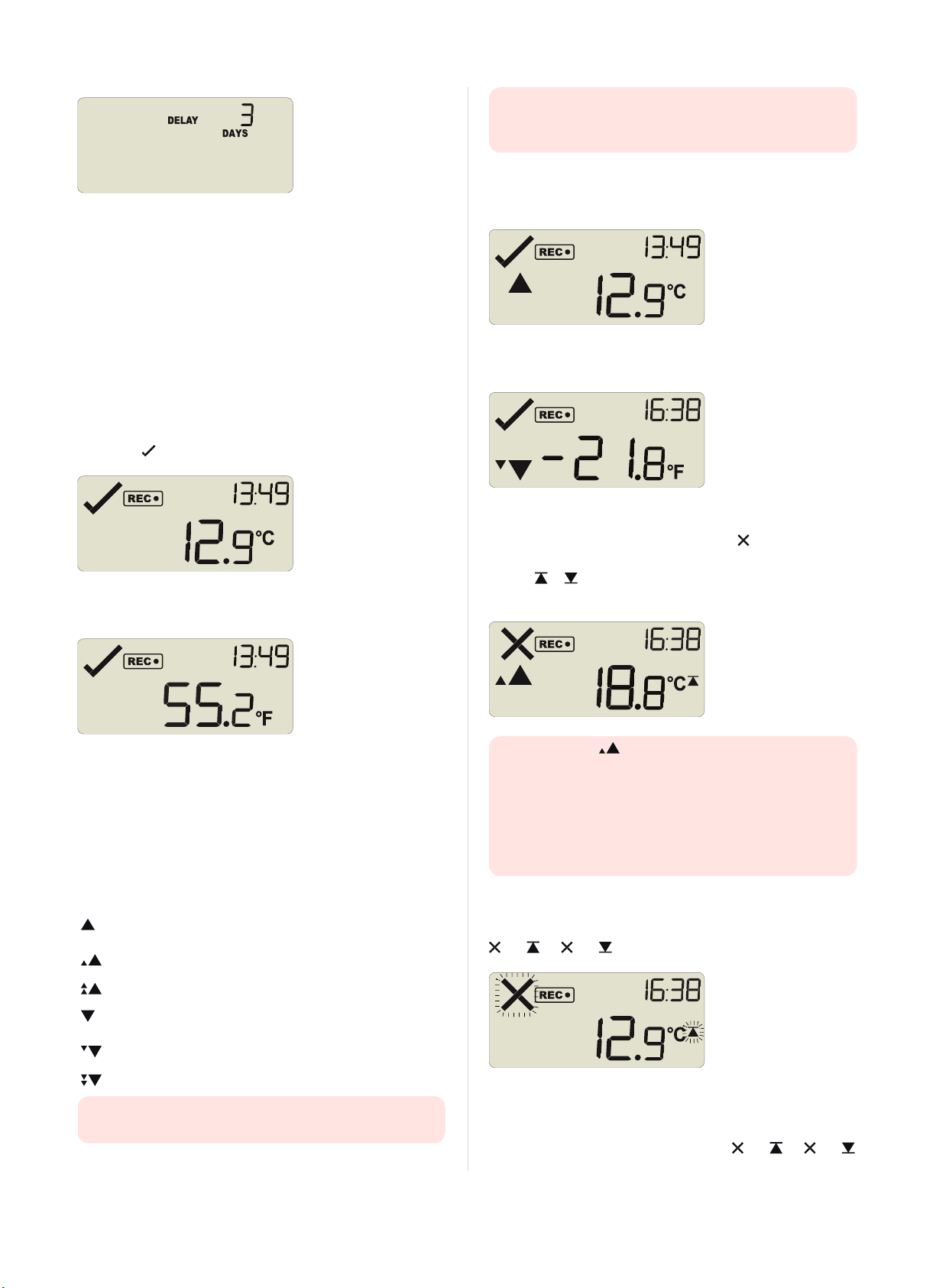
If a user presses the START/Mark button during the start delay
phase, the start delay value is reset to its originally configured value.
Automatic date/time start
If you configured the UTRID-16 for a date/time start, it will record
temperature values as soon as the entered date and time have passed.
If the recorder is still plugged into a USB port when the start time
passes, the recorded readings will show USB Paused on the PDFand
in the software.
During Recording
During normal operation the display shows the most recently recorded
temperature. The current time is also displayed in 24 hour format. A
tick symbol is shown as long as no alarm event has occured.
Temperatures can be shown in Celsius (as above) or Fahrenheit (as
below).
temperature recorded was above or below the corresponding
alarm threshold value, and the alarm was configured with a delay
value.
In this example the most recently recorded t emperature is above the
primary high alarm threshold, but below a secondary threshold; an
alarm event has not been triggered:
Here, the temperature was below the secondary alarm threshold, but
above the tertiary threshold; an alarm event has not been triggered:
An alarm event was triggered
If an alarm event occurred, the alarm indicator is displayed in the
upper left corner of the display. Additionally, one of the alarm limit
markers or is displayed, to show if the event was an upper or a
lower alarm.
The temperature unit on the display is the same as used for the PDF
and CSV files. It is set during configuration.
Readings above or below alarm thresholds
If the most recently recorded t emperature is above or below one of t he
alarm thresholds, one or more alarm markers will be shown on the
display.
This symbol is
displayed ...
The presence of an alarm marker on the display does NOT
indicate an alarm event. It only shows that the most recent
... when the most recent temperature recorded
is
above the primary upper alarm threshold, but
below the secondary
above the secondary upper alarm threshold, but
below the tertiary
above the tertiary upper alarm threshold
below the primary lower alarm threshold, but
above the secondary
below the secondary lower alarm threshold, but
above the tertiary
below the tertiary lower alarm threshold
The alarm marker in this screen does not indicate which
alarm threshold caused the alarm, only t hat the most recent
temperature recorded, which you see on the display (18.8°C) was
above the secondary threshold.
To identify which of the alarm conditions cause the alarm event
you will need to review the data on screen as described in
Reviewing Alarms on page12, or open the PDF file on your PC.
Clearing an alarm
A UTRID-16 can be configured so you can clear an alarm from the
display. To do this, press and hold the START/Mark button. The
and (or and ) symbols will start t o blink.
After approx. 4 seconds both symbols will remain permanently lit for
2 seconds. If you release the button during this time, the alarm will
be cleared. If the button is released earlier t han 4 seconds or later
than 6 seconds, the display continues to show and (or and
Find Quality Products Online at: [email protected]
Page 1 0 of 21 UTRID-16 Pro duct User Gui de, Revisio n 1, copyright © 2004- 2016, Lo gTag®Recorders . All rig hts reserved.
www.GlobalTestSupply.com
Page 11
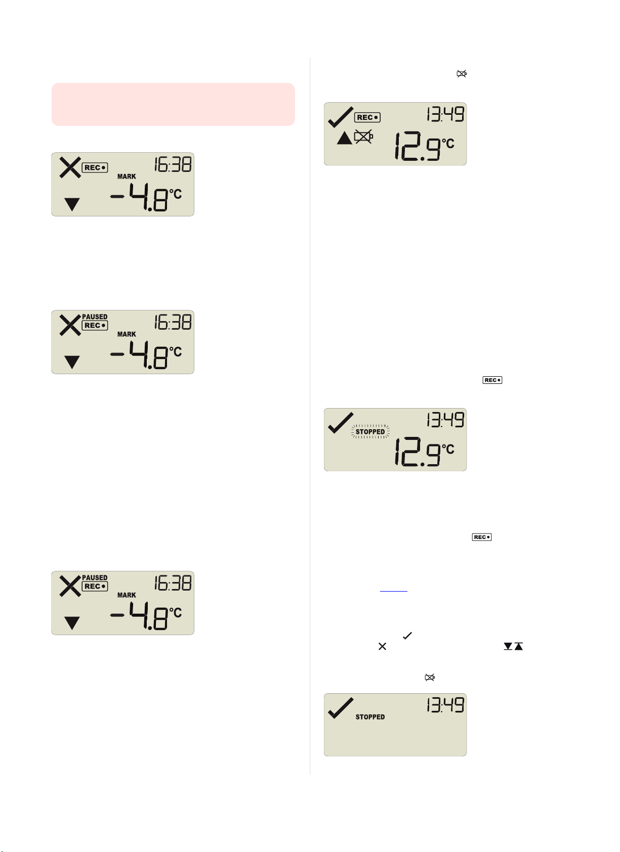
) symbols. In any case an inspection mark will be recorded against the
next temperature reading taken.
An alarm cannot be cleared once the UTRID-16 has stopped
recording. Alarms resulting from an accumulation of readings can
also not be cleared.
Setting an Inspection Mark
When you press the START/Mark button while the UTRID-16 is
recording temperature, an inspection mark is recorded against the
next temperature reading. The MARK symbol appears and remains
shown until the next reading is taken.
If the Paused Readings function is enabled, you will also see the
PAUSED symbol.
Paused Readings
During configuration of the UTRID-16 you can set the option to ignore
a set number of readings for alarm- and statistics calculations after
either button is pressed. The readings are still shown on the graph
and in the data listing, but their value is ignored when determining
alarm conditions, minimum/maximum values and MKT calculations.
This function is useful when you wish to review readings during the
recorder's operation (or clear an alarm), but you do not wish to trigger
an alarm due t o your handling the product. It allows the recorder to
acclimatise to the environmental conditions again, before further
readings are processed.
After a button press the display shows the word PAUSED above the
recording symbol. PAUSED will turn off as soon as the last ignored
reading has been recorded.
If the battery is low while the UTRID-16 is still recording
temperatures, the battery low symbol is shown in addition to any
other currently displayed information.
Stopping the UTRID-16
Automatically
The UTRID-16 automatically stops recording temperature when the
maximum number of readings specified during configuration has been
reached. Your unit can also be set up to stop when it is inserted into a
USB socket. This option needs to be set up at the factory and cannot
be changed during configuration with LogTag®Analyzer. Your
distributor can supply more information about this option.
Manually
You can configure a UTRID-16 so it can be stopped with the STOP
butt on. This feature is useful when you take the recorder out of a
shipment and don’t want to falsify the statistics with readings taken
after the shipment c ompletion. The stop function is enabled in the
Advanced Options dialogue during configuration.
Press and hold the STOP/Review button. immediately
disappears, and the ST OPPED symbol blinks for 4 seconds.
The symbol then shows permanently for 2 seconds. If you release the
butt on during this t ime, the recorder stops taking temperature
readings.
If the button is released while STOPPED is still blinking, or you
wait until it disappears, the display shows again, and the
recorder continues recording data. In this case an inspection mark
will be recorded in the data against the next temperature reading.
The MARK symbol will show, and the P AUSED symbol also shows
if this feature is enabled.
Recorder has stopped
Once the recorder has stopped, t he display will show:
l
The STOP PED symbol
l
The OK indicator ( )if no alarm was recorded
l
Paused readings are marked with a blue dot on the graph, and a $
sign next to the reading in the data list.
The option is set in the advanced options dialogue in LogTag
®
The alarm ( )and one or both alarm threshold( ) indicators,
if an alarm was recorded during the trip
l The current time
l
The battery low symbol ( ), if the battery is low.
Analyzer and is expressed in multiples of the logging interval.
The length of time t he recorder shows PAUSED is therefore
dependent on when during the log interval you press one of the
butt ons.
Battery Low while recording
Find Quality Products Online at: [email protected]
Page 1 1 of 21 UTRID-16 Pro duct User Gui de, Revisio n 1, copyright © 2004- 2016, Lo gTag®Recorders . All rig hts reserved.
www.GlobalTestSupply.com
Page 12
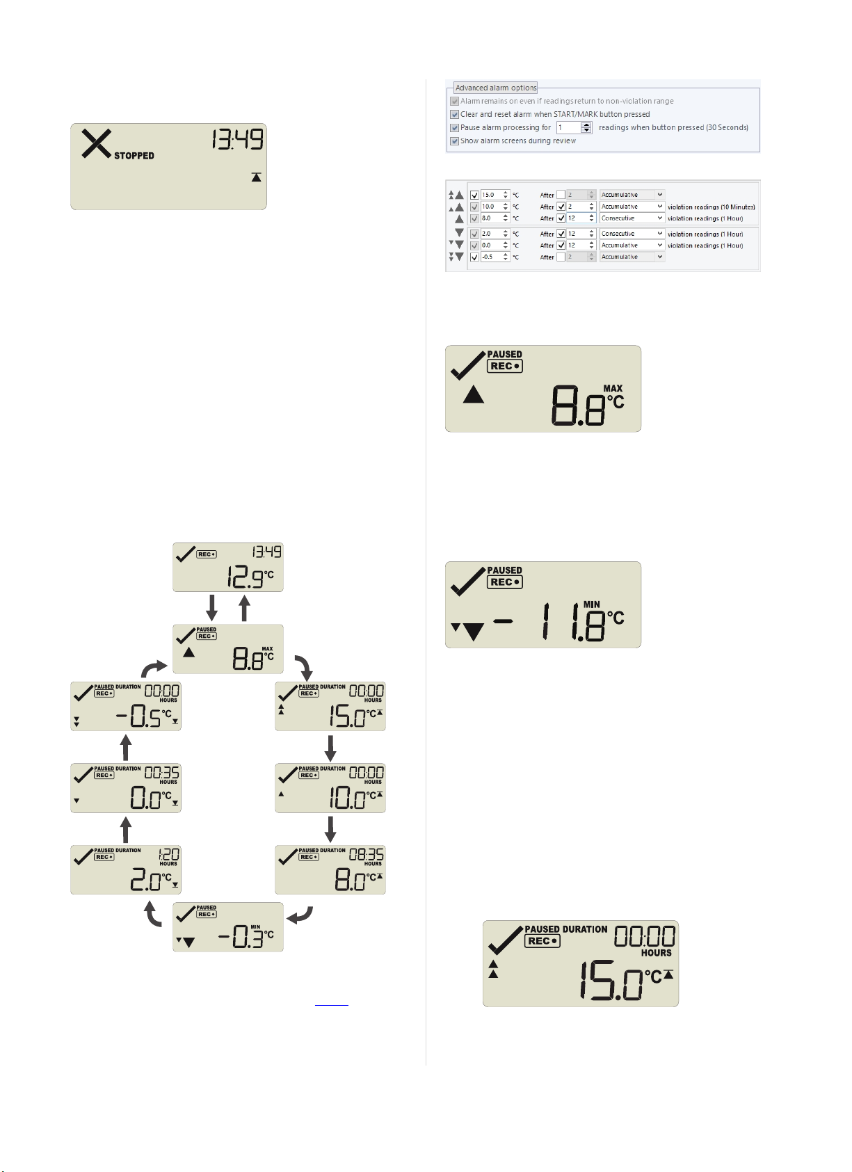
The recorder has stopped, and no alarms were recorded during the
STOP
Review
STOP
Review
STOP
Review
STOP
Review
STOP
Review
STOP
Review
STOP
Review
STOP
Review
STOP
Review
START
Mark
trip.
Here, the recorder has stopped, and an upper alarm was recorded
during the trip.
In the example following alarm settings are used:
Reviewing Alarms
At any time you can review the recorded statistics by briefly pressing
the STOP/Review button. You can do this while the recorder is
still taking t emperature readings, or when it has already stopped, but
not when it is plugged into a USB port.
After each subsequent press of STOP/Review the next review
screen is shown. The number of screens available for review depends
on the number of configured alarms, and whether or not the alarm
review screens have been enabled. If no alarms are configured, or the
alarm review screens are disabled, only t he MIN and MAX screens
appear. If 6 alarms are configured and the alarm review screens are
enabled (which is the maximum), 8 screens will appear.
You can terminate the review at any time by pressing
START/Mark, or by waiting 30 seconds without pressing any
butt on.
Figure 7: Alarm configuration settings in LogTag®Analyzer
On first press of STOP/Review the Maximum Reading screen
appears.
The clock disappears, and the MAX symbol is shown along with the
maximum temperature recorded. If this temperature was above or
below one of the alarm thresholds, the corresponding alarm marker is
also shown. Here, the maximum was above the primary threshold.
When you press STOP/Review again, the Minimum Reading
screen appears.
If this temperature was above or below one of the alarm thresholds,
the corresponding alarm marker is also shown. Here, the minimum
was below the tertiary threshold.
If the alarm review screens are enabled, the next screens show the
enabled alarm threshold values in descending order, starting with the
upper most alarm threshold. Up to six screens will be shown,
depending on how many alarms were enabled during configuration.
The Minimum Reading screen is shown after the primary upper and
before the primary lower alarm screen.
1.
In this example the tertiary upper alarm is enabled, indicated
by the alarm threshold marker shown in combination with
the two small alarm arrows. The DURATION symbol is
shown, and the clock shows t he total number of hours and
minutes above the threshold, instead of the time.
Figure 6: Review cycle with all alarms en abled
The sample screens assume you have activated the Paused
functionality and have enabled the alarm review screens:
www.GlobalTestSupply.com
Find Quality Products Online at: [email protected]
Page 1 2 of 21 UTRID-16 Product User Guide, Revisio n 1, copyright © 2004- 2016, Lo gTag®Recorders . All rig hts reserved.
Page 13
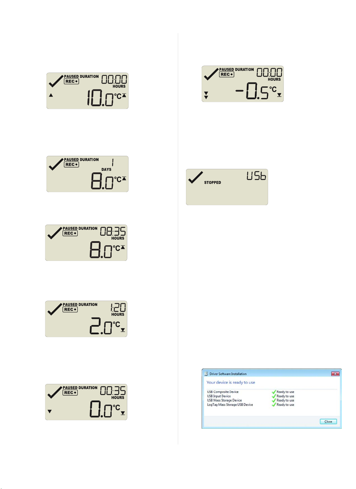
You can see how long the recorded temperature was above
this threshold. Here, the 15°C threshold was not exceeded.
2.
The secondary upper alarm is shown next, indicated by the
alarm threshold marker shown in combination with a single
small alarm arrow.
As with the previous alarm the 10°C threshold was not
exceeded.
3.
The primary upper alarm is shown next, indicated by the
alarm threshold marker shown without any small alarm
arrows.
In this example the temperature was above 8°C for 1 day, 8
hours and 35 minutes. If the duration is longer than 24 hours,
the display will alternate between showing days and hours.
In this example, the temperature was lower than the
secondary threshold for 35 minutes.
6.
The tertiary lower alarm is shown next, indicated by the
alarm threshold marker shown with two small alarm arrows.
In this example, the temperature was not lower than the
tertiary t hreshold.
Plugging the UTRID-16 into a USB port
As soon as you plug the UTRID-16 into a USB port, the word U S b
appears and remains permanently on until all files have been
generated.
When complete, U S b starts blinking once per second.
4.
The primary lower alarm is shown next, indicated by the
alarm threshold marker shown without any small alarm
arrows.
In this example, the temperature was lower than the primary
threshold for 1 hour and 20 minutes.
5.
The secondary lower alarm is shown next, indicated by the
alarm threshold marker shown without one small alarm
arrow.
What happens on your computer depends on the operating system of
the computer, the settings made during configuration and whether or
not LogTag®Analyzer is running.
Microsoft Windows
Up to four drivers will now be installed, depending on the UTRID-16's
configuration.
All drivers are part of the operating system and will typically not
require administrator privileges for your computer.
1. Mass Storage Device
2.
LogTag Mass Storage USB Device
These two devices are required so you can access the data files
in the same way as a USB memory stick. These drivers will
not be installed if the UTRID-16 does not generate files.
3.
USB Input Device (HID)
This device is used for c ommunication to LogTag®Analyzer
and its driver will always be installed, even if LogTag
Analyzer is not present on the computer.
4.
USB Composite Device
®
Find Quality Products Online at: [email protected]
Page 1 3 of 21 UTRID-16 Product User Guide, Revisio n 1, copyright © 2004- 2016, Lo gTag®Recorders . All rig hts reserved.
www.GlobalTestSupply.com
Page 14

If you have configured t he UTRID-16 to generate files, these will be
created every time you plug the recorder into the USB port.
Once finished, U S b will blink every second to indicate these files can
now be accessed.
a new drive or mounted device will appear. The device name will be
created from the serial number of the UTRID-16.
configuration.
While a UTRID-16 is plugged into USB, no t emperature readings
are taken. The graph will display a gap and the data list will
show --- followed by the # symbol. This also applies when the
recorder is connected to a USB power supply.
Accessing the files
If the recorder was configured to generated files, a new drive or
mounted device will appear. The device name will be created from
the serial number of the UTRID-16. You can access the files by
browsing to the newly created drive and double-clicking the PDF,
CSV or LTD files. For PDF files you need Adobe Acrobat Reader or a
similar PDF viewer. To open t he LTD file you need to install the free
LogTag®Analyzer software. CSV files can be opened with a text
editor, or imported into a spreadsheet program such as Microsoft
ExcelTM.
The file names contain information about t he recorded data, which is
detailed in the section about Interpreting the Data on page1. If a
recorder has only taken pre-start readings, PDF and CSV files will not
be created.
You should copy the files generated by the recorder to a
permanent storage location on your computer, such as the
Documents folder, as they are not automatically copied.
The data on the unit is retained, and each time you plug the
UTRID-16 back into the computer the files are re-generated,
albeit with a new file name. Once the battery is exhausted,
however, the real time clock on the unit stops and dates and
times may no longer be accurate.
Find Quality Products Online at: [email protected]
Page 1 4 of 21 UTRID-16 Product User Gu ide, Revision 1, copyright © 2004- 2016, Lo gTag®Recorders . All rig hts reserved.
www.GlobalTestSupply.com
Page 15
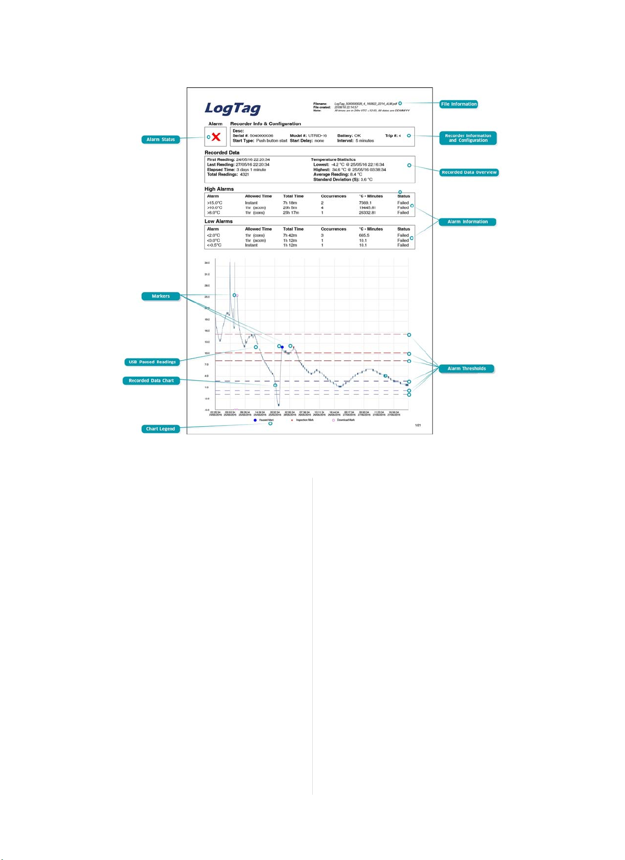
Interpreting the Data
Figure 8: Sample report page with Multiple Alarm Thresholds
Data Evaluation - Report with multiple alarms
Alarm Status
This shows at a glance if the UTRID-16 recorded alarm conditions
during the trip (showing a red✖) or if no alarms were recorded
(green✔).
File Information
This section shows general information about the PDF file, such as
generation time, date and time formats and the file name, which is
compiled from information about the data it contains:
LogTag_[se rial_num ber]_ [trip number ]_[file crea tion date]_file creation time ]_[OK or ALM].
Recorder Information and Configuration
On recorders with multiple alarms these sections are combined and
show general information such as serial and model numbers, trip
number, battery status and description. It shows how the recorder
was started, if a start delay was active and the interval used for taking
readings.
High Alarm and Low Alarm Information
These two sections summarize the alarm occurences during the trip,
includingstatistical data.
Recorded Data Chart
The chart shows a graphical representation of the data during the
trip. As part of the UTRID-16 configuration process you set the
parameters that influence how the chart is presented.
Markers
The chart will show marks where the UTRID-16 has been downloaded
(º) or where an inspection mark has been placed with t he
START/Mark or STOP button (•). It also shows Paused marks
(•) where a button press has prevented readings from being used for
statistics and alarm calculations.
USB Paused Readings
A gap is shown in the graph where the UTRID-16 was plugged into a
USB port at the time it would otherwise have taken a reading.
High Alarm and Low Alarm Information
These two sections summarize the alarm occurences during the trip,
includingstatistical data. You may see up to 5 alarms for each
direction, depending on configuration and zoom settings.
Upper Threshold values
The upper alarm thresholds are shown with red dashed lines ---- so
you can see at a glance where t emperatures went above set limits.
You may see up to three lines depending on configuration and zoom
settings.
Lower Threshold values
The lower alarm thresholds are shown with blue dashed lines ---- so
you can see at a glance where t emperatures went below set limits.
You may see up to three lines depending on configuration and zoom
settings.
Find Quality Products Online at: [email protected]
Page 1 5 of 21 UTRID-16 Product User Guide, Revision 1, copyright © 2004- 2016, L ogTag®Recorders . All rig hts reserved.
www.GlobalTestSupply.com
Page 16

Chart Legend
Shows the symbols for download marks, inspections marks and
paused marks if they appear in the readings.
Find Quality Products Online at: [email protected]
Page 1 6 of 21 UTRID-16 Product User G uide, Revision 1, copyright © 2004- 2016, Lo gTag®Recorders . All rig hts reserved.
www.GlobalTestSupply.com
Page 17
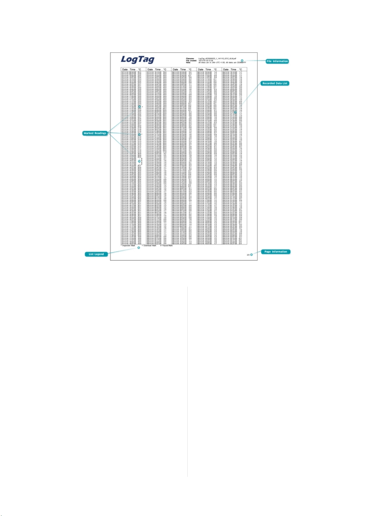
Figure 9: S ample Data List
Data Evaluation - Data List
File information
The information from the report page is repeated here.
Recorded Data list
The Data list shows a single row for each recorded reading, along with
the with date, time and t emperature values, plus any special events
that were recorded against t his reading.
Marked readings
In the data list readings are marked after the temperature value...
l ...with a + symbol where the UTRID-16 has been downloaded
with LogTag®Analyzer.
l ...with a * symbol where an inspection mark has been placed with
the START/Mark or STOP/Rev iew button.
l ...with a $ symbol where readings were paused as a result of a
butt on press.
l ...with a # symbol where the recorder was plugged into a USB
port at the time it would otherwise have taken a reading.
List legend
Shows the symbols for download marks, inspections marks,
paused and USB paused readings if they appear in the data.
Page information
Curent page number and total number of pages appear on every page.
Tips and Tricks
Configuration
When configuring a USB recorder, allow enough time for the unit to
acclimatise to the target environment, particularly if you have
configured an upper alarm. This can be best achieved with a start
delay, or a date/time start if you know when the shipment takes
place.
Make sure you remove your UTRID-16 from the USB socket when you
use a date/time start, so it starts at the time you want, rather than
when unplugged from the port.
During the trip
Always replace t he USB protect ive cap before placing the UTRID-16
with the goods. While recording, make sure the UTRID-16's protective
cap is facing down. The protection rating can only be achieved when
used in this orientation. For applications requiring a higher IP rating
the unit should be used in the protective case, available as an
accessory.
Find Quality Products Online at: [email protected]
Page 1 7 o f 21 U TRID-16 Pro duct User Guid e, Revisio n 1, copyright © 2004- 2016, Lo gTag®Recorders . All rig hts reserved.
www.GlobalTestSupply.com
Page 18
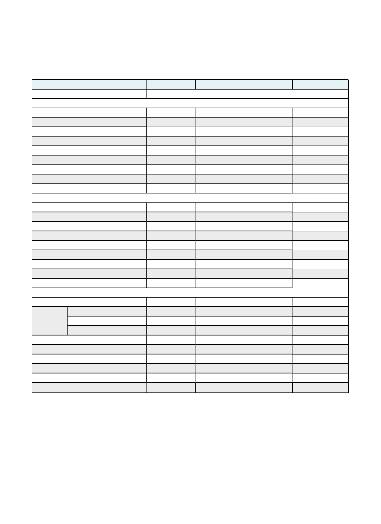
UTRID-16 Factory Presets
Description Default Profile Range/Option Your requirement
Profile Name
Standard Options
UserID - ASCII text up to 38 characters
1
-
Start method Push but ton start Push button start Push but ton start
Record pre-start readings enabled enabled or disabled
Number of readings to record 8,000 1-16,129
Sampling interval 5 minutes 1 minute t o 18 hours
Start Delay 60 minutes 1 minute to 72 hours, 0=no delay
Configure requires password disabled enabled or disabled
Download requires password disabled enabled or disabled
Password - Up to 6 ASCII characters
Advanced File Options
Generate PDF file enabled enabled or disabled
Generate LTD file enabled enabled or disabled
Generate CSV file disabled enabled or disabled
Temperature units °C °C or °F
Time Zone UTC +0:00 -12:00 to +14:00 in 15min steps
Time format 24-hour 24-hour or 12 hour (am/pm)
Date format DD/MM/YY DD/MM/YY or MM/DD/YY
Calculate MKT enabled enabled or disabled
Activation Energy default default or custom value (please specify)
PDF Options
Generate Data List enabled enabled or disabled
Y-Axis scaling
Range range of readings range of readings, range of sensor or custom
Custom upper
2
- -25°C to 60°C (-13°F to 140°F)
Custom lower - -25°C to 60°C (-13°F to 140°F)
Show Y-axis grid lines enabled enabled or disabled
Show X-axis grid lines enabled enabled or disabled
Show upper alarm line disabled enabled or disabled
Show lower alarm line disabled enabled or disabled
Allow stopping with STOP/Re view button
enabled enabled or disabled
Prioritise download over file generation disabled enabled or disabled
LogTag®UTRID-16 recorders can be client configured using LogTag®Analyzer. For an out-of-box solution they can also be ordered in volume, preconfigured with a factory profile, ready for starting.
If a default configuration does not suit, customers can compile their own profile by specifying the parameters in the tables below when ordering.
Please note that minimum order quantities apply for UTRID-16 recorders with profiles not stocked by LogTag®Recorders .
1
All units associated with a profile must have the same UserID. The text c annot be individually cu stomised per u nit. The text c annot c ontain characters f rom an extended ch aracter set
such as Chinese or Cyrillic
2
Upp er value must be above lower value
Find Quality Products Online at: [email protected]
Page 1 8 of 21 UTRID-16 Pro duct User Gui de, Revisio n 1, copyright © 2004- 2016, Lo gTag®Recorders . All rig hts reserved.
www.GlobalTestSupply.com
Page 19
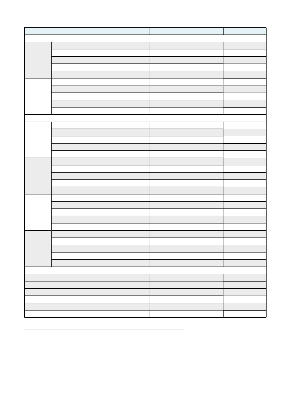
Description Default Profile Range/Option Your requirement
Standard Alarm Parameters
Upper Alarm
Alarm direction upper upper Upper
Trigger this alarm disabled enabled or disabled
Temperature threshold value
3
- -25°C to 60°C (-13°F to 140°F)
Alarm activation type
4
instant instant, accumulative or consecutive
Activation delay time - 1 minute t o 45 days
Lower Alarm
Alarm direction Lower Lower Lower
Trigger this alarm disabled enabled or disabled
Temperature threshold value - -25°C to 60°C (-13°F to 140°F)
Alarm activation type instant instant, accumulative or consecutive
Activation delay time - 1 minute t o 45 days
Multi-AlarmParameters
5
Alarm 3
Alarm direction - upper or lower
Trigger this alarm disabled enabled or disabled
Temperature threshold value - -25°C to 60°C (-13°F to 140°F)
Alarm activation type instant instant, accumulative or consecutive
Activation delay time - 1 minute t o 45 days
Alarm 4
Alarm direction - upper or lower
Trigger this alarm disabled enabled or disabled
Temperature threshold value - -25°C to 60°C (-13°F to 140°F)
Alarm activation type instant instant, accumulative or consecutive
Activation delay time - 1 minute t o 45 days
Alarm 5
Alarm direction - upper or lower
Trigger this alarm disabled enabled or disabled
Temperature threshold value - -25°C to 60°C (-13°F to 140°F)
Alarm activation type instant instant, accumulative or consecutive
Activation delay time - 1 minute t o 45 days
Alarm 6
Alarm direction - upper or lower
Trigger this alarm disabled enabled or disabled
Temperature threshold value - -25°C to 60°C (-13°F to 140°F)
Alarm activation type instant instant, accumulative or consecutive
Activation delay time - 1 minute t o 45 days
Advanced Display Options
Alarm remains active when readings return to spec enabled enabled or disabled
Clear alarm with START/Mark button
enabled enabled or disabled
Pause alarm/statistics processing for X readings 0 (disabled) 0 (disabled) t o 255
Switch off display after 30 seconds (Power save) enabled enabled or disabled
Show alarm screens during review disabled enabled or disabled
Allow reset of the recorder with the start button disabled enabled or disabled
3
Upp er value must be above lower value
4
l Instant = one temperature reading is above (below) the threshold
l Consecutive = temperature readings are above (below) the threshold f or th e time def ined in th e activation d elay without interruption
l Accu mulative = temp erature readings are above (below) the threshold for the total time defined in the act ivation delay time, but may not necessarily be sequent ial.
5
Only on model "M"with multip le alarms.
Find Quality Products Online at: [email protected]
Page 1 9 of 21 UTRID-16 Product User G uide, Revision 1, copyright © 2004- 2016, Lo gTag®Recorders . All rig hts reserved.
www.GlobalTestSupply.com
Page 20

For rules regarding setting up mult iple alarms please see Alarm Configuration Options on page6.
Find Quality Products Online at: [email protected]
Page 2 0 of 21 UTRID-16 Pro duct User Gui de, Revisio n 1, copyright © 2004- 2016, Lo gTag®Recorders . All rig hts reserved.
www.GlobalTestSupply.com
Page 21

Technical Specifications
Model Number
UTRID-16
Temperature Sensor Measurement Range
-25°C to +60°C (-13°F to +140°F)
Operating T emperature Range
-25°C to +60°C (-13°F to +140°F)
Storage Temperature Range
0°C to +40°C (32°F to +104°F)
Ambient humidity range during transport and us e
0 to 95%RH
Rated Temperature Resolution
0.1°C (0.1°F) across entire range
Rated Temperature Accuracy
l Better than ±0.5°C (±0.9°F) for -20°C to +40°C (-4°F to 104°F)
l Better than ±0.7°C (±1.3°F) for -25°C to -20°C (-13°F to -4°F)
l Better than ±0.7°C (±1.3°F) for +40°C to +60°C (104°F to 140°F)
Sensor Type
Precision thermistor
Sensor Reaction Time
Typically less than 7 minutes (T90) in moving air (1m/s), method as detailed
in EN12830:1999.
Cloc k accuracy
Quartz crystal locked real tim e clock, rated accuracy ±25ppm @ 25°C (equiv to
2.5 seconds/day)
Rated temperature coeffi cient is -0.034±0.006ppm/°C (i.e. typically +/-
0.00294seconds/day/°C)
Recording Capacity
16,129 real tim e temperature values, giving
l 112 days @ 10min logging or
l 168 days @ 15min logging.
Environmental
IEC 60529: IP64 with USB cap fitted
Fits into IP67 Protective Enclosure 200-000020
Case Material
Polycarbonate
Power source
CR2032 3V Li -MnO2battery – User replaceable coin cell, non-rechargeable
Battery life
Typically 1 year of operation with normal use (6 m inute logging, statistics
reviewed on the display no m ore than once dai ly for no longer than 30
seconds each tim e, download data monthly) provided recorder is kept within
the storage temperature range when not in use.
Size
93mm(H) x 54.5mm (W) x 8.6mm (T) including USB cap
Weight
39g
Calibration
Calibration traceable to an ISO/IEC 17025 accredited testing laboratory
PDF features
l compliant with standard 1.6 and later
l Single page report with trip and alarm summary
l Multi page report with list of readings including date/time
Download time
l Typically with full memory ( 16,129 readings) less than 30 seconds
from time of insertion to ava ilability of PDF report.
l Typically less than 10 seconds from time of insertion to avai lability
of LTD file in LogTag®Analyzer (if configured)
Software requirements
l LogTa g
l PDF reader software to access onboard PDF fi les
®
Analyzer version 2.8 or later to configure and download
Statistics memory
for displaying statistics on LCD
l Max/Min values
l Alarm duration values.
Memory type
Non volatile
Sampling Interval
Configurable from 30 seconds to 18 hours.
Start options
l Push button start with optional configurable start delay from 1
minute to 72 hours
l Date/time start
Alarm functions
l three configurable upper alarms
l three configurable lower alarms
l OK tick and Alarm cross on display, linked to alarms
Vibration
Withstands vibration specifi cation as detailed in EN12830:1999
Shock
l Withstands shock specification a s detailed in EN12830:1999
l Withstands 5 drops from 1m onto smooth concrete floor without loss
of function or calibration
EMC compliance
l EC E MC directives (EN 61000-6-1:2005 & EN 61000-6-3:2006)
l Includes electrostatic discharge as prescribed in E N 61000-4-2
l Complies with FCC Part 15 Subparts A and B
USB compatibility
USB 2.0, type A plug
Accessories
l Wall holder 200-000010
l IP67 Protective Enclosure 200-000020
l Replacement protective cap 200-000425
Find Quality Products Online at: [email protected]
Page 2 1 of 21 UTRID-16 Product User Guide, Revisio n 1, copyright © 2004- 2016, Lo gTag®Recorders . All rig hts reserved.
www.GlobalTestSupply.com
Page 22
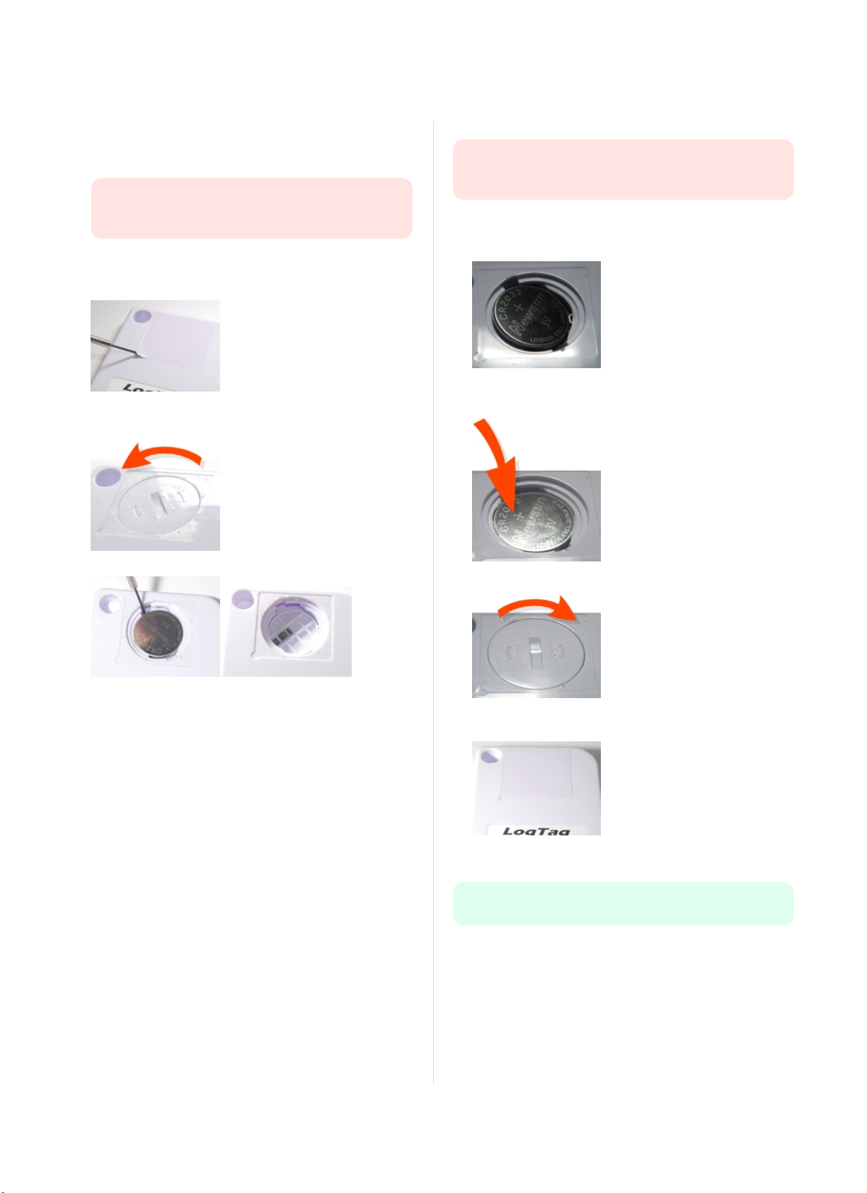
Appendix 1 - Battery Replacement
Prepare the recorder
l
Download the unit to save any recorded data.
l
Hibernate the unit using LogTag®Analyzer.
Failing to hibernate the recorder may result in serious
memory corruption. As a result you may no longer be able to
use this product.
Remove the old battery
l
Carefully remove the rear label covering the battery door using a
small-bladed screwdriver or knife:
l
Use a coin to turn the battery door anti-clockwise; remove it from
the case:
Insert the new battery
Only use batteries from a reputable manufacturer! Check the
operational temperature range of the battery and make sure it
covers the range of the UTRID-16.
l
Put a new CR2032 cell into the battery compartment as shown;
the right hand edge of the batt ery is inserted first against the
contact:
l
Press firmly down on the left hand side of the battery to click the
battery into place:
l
Remove the battery using a small-bladed screwdriver, as shown:
l
Replace the battery door; turn clockwise to lock it into place.
l
Cover the battery door with either a new label (Part # 100-
000502) or reuse the old one.
l
Re-configure the recorder with LogTag®Analyzer.
Please recycle or dispose of the old battery according to your local
environmental regulations.
Find Quality Products Online at: [email protected]
Page i o f 1 UTRID-16 Pro duct User Gui de, Revisio n 1, copyright © 2004- 2016, Lo gTag®Recorders . All rig hts reserved.
www.GlobalTestSupply.com
 Loading...