

Page 1
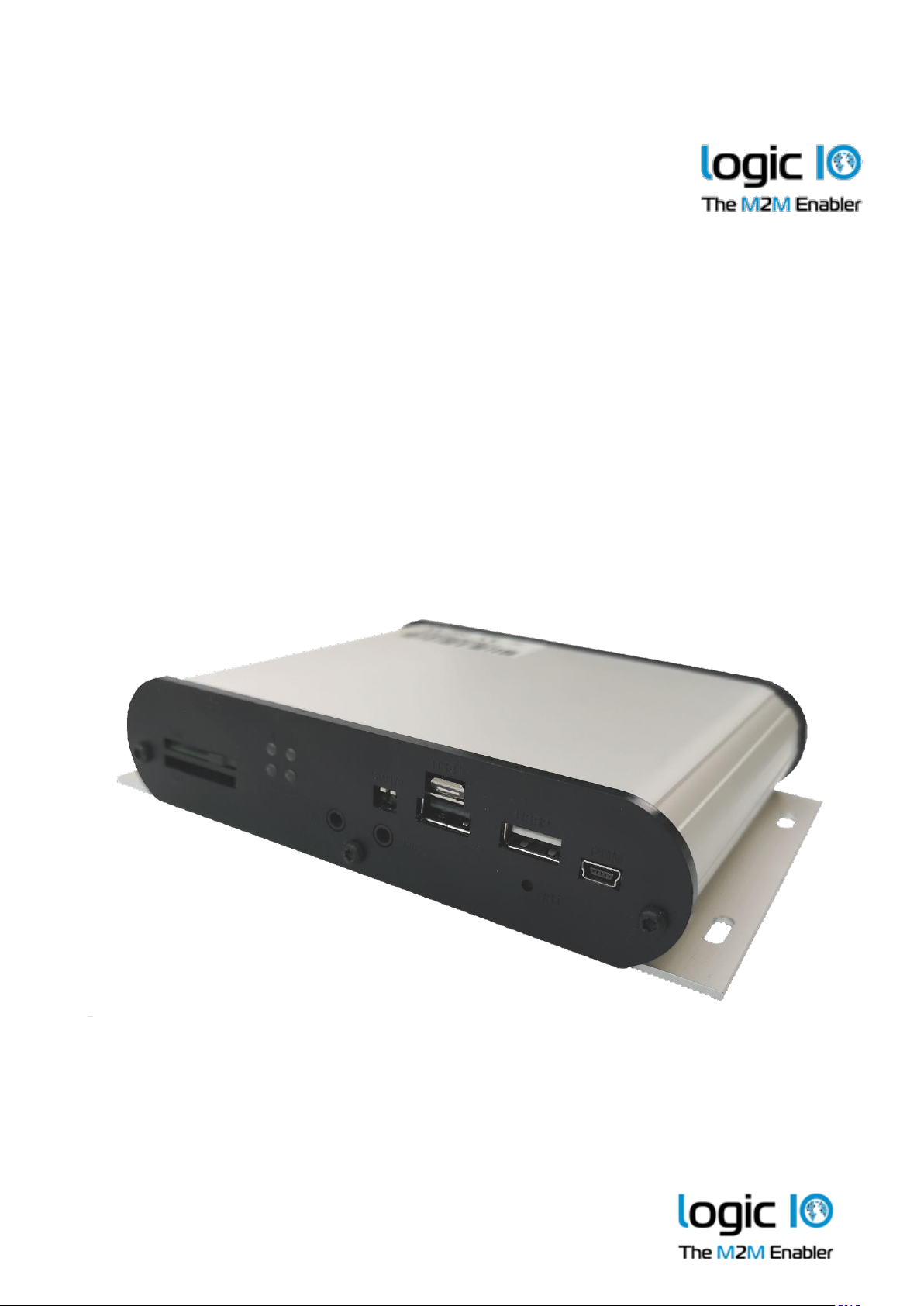
RTCU NX-200
Advanced Automotive M2M/IoT Gateway
Technical Manual
Version 1.00
Page 2

RTCU NX-200 Technical Manual V1.00
Advanced Automotive M2MI/IoT Gateway
Logic IO ApS. Ph: (+45) 7625 0210
Holmboes Allé 14 Fax: (+45) 7625 0211
8700 Horsens Page 2 of 45 Email: [email protected]
Denmark www.logicio.com
Introduction
The RTCU NX-200 is the most advanced automotive IIoT Gateway product available on the
market today. Based on the successful hardware architecture from the RTCU NX-400, it features an
added range of sophisticated automotive features like a full-motion sensor suite, dual CAN bus
interfaces, Worldwide LTE, and a slick aluminium encapsulation with a clear reference to the
popular RTCU MX2 turbo!
The device is based on the new NX32L (NX32 for Linux) architecture, which embraces many new
technologies and at the same time maintains full backward compatibility, which ensures already
implemented and tested NX32 applications can execute without changes.
The RTCU NX-200 is designed to meet the ever-increasing challenges on security, in that it offers
full TLS on all major protocols and includes a hardened protected execution environment with
dual-boot and automatic fallback and recovery.
The RTCU NX-200 device is an automotive-grade device that is designed from the ground up for
professional M2M / IIoT applications with its strong on-board I/O capabilities and multiple
communication interfaces such as World-wide cellular LTE, WLAN, Bluetooth Classic / LowEnergy, dual CAN bus, Ethernet, dual RS232, RS485, and 1-Wire.
The RTCU NX-200 also sports two USB host port interfaces allowing for the expansion of the
device with accessories such as RFID reader, additional Ethernet port, and additional RS232/RS485
ports
The on-board I/O system can be expanded almost indefinitely and completely transparently by
adding Modbus I/O modules.
The RTCU NX-200 is fully software and hardware compatible with the RTCU MX2 turbo.
The advanced power-management features on the RTCU NX-200 combined with the on-board
high-capacity Li-Ion battery allows the device to stay in a power-saving mode for a longer period
still being connected to the cellular network and capable of waking up on for example cellular
activity, change of digital inputs or a vibration sensor
This manual contains technical documentation on the installation and usage of the RTCU NX-200
device. For detailed information on the programming and software configuration of the product,
please refer to the RTCU IDE documentation.
For detailed information on the powerful RTCU M2M Platform, please refer to the
RTCU M2M Platform datasheet and the RTCU IDE documentation.
Page 3

RTCU NX-200 Technical Manual V1.00
Advanced Automotive M2MI/IoT Gateway
Logic IO ApS. Ph: (+45) 7625 0210
Holmboes Allé 14 Fax: (+45) 7625 0211
8700 Horsens Page 3 of 45 Email: [email protected]
Denmark www.logicio.com
* * * * THIS PAGE IS INTENTIONALLY LEFT BLANK * * *
Page 4

RTCU NX-200 Technical Manual V1.00
Advanced Automotive M2MI/IoT Gateway
Logic IO ApS. Ph: (+45) 7625 0210
Holmboes Allé 14 Fax: (+45) 7625 0211
8700 Horsens Page 4 of 45 Email: [email protected]
Denmark www.logicio.com
Table of contents
Introduction ...................................................................................................................................................... 2
Important Information .................................................................................................................................... 6
Technical Highlights ....................................................................................................................................... 7
Graphical overview: ........................................................................................................................................ 9
External connections ..................................................................................................................................... 10
Overview .................................................................................................................................................... 10
Signal Overview ........................................................................................................................................ 11
Power supply ............................................................................................................................................. 15
Digital outputs ........................................................................................................................................... 16
Digital Inputs / Ignition Input ................................................................................................................. 17
Analog Inputs ............................................................................................................................................ 18
Flex Inputs .................................................................................................................................................. 19
CAN communication port ....................................................................................................................... 21
RS232 port 1 ............................................................................................................................................... 22
RS232 port 2 ............................................................................................................................................... 22
RS485 communication ports (EIA/TIA-485-A compatible) ................................................................. 23
1-Wire bus .................................................................................................................................................. 23
DC-Out ........................................................................................................................................................ 24
Ethernet ....................................................................................................................................................... 24
USB Host interface .................................................................................................................................... 24
Audio interface .......................................................................................................................................... 24
3D movement sensor ..................................................................................................................................... 26
LED Indicators ............................................................................................................................................... 27
User LED A and B ..................................................................................................................................... 27
System LED S1 and S2 .............................................................................................................................. 28
Switches .......................................................................................................................................................... 29
DIP-switch .................................................................................................................................................. 29
System switch (RST).................................................................................................................................. 29
Internal Li-Ion battery ................................................................................................................................... 30
World-wide LTE Cat. 4 Cellular Engine ..................................................................................................... 31
WLAN and Bluetooth ................................................................................................................................... 31
WLAN Technical Data .............................................................................................................................. 31
Bluetooth Technical Data ......................................................................................................................... 31
99-channels multi-GNSS receiver ................................................................................................................ 32
Internal / External SIM-Card readers .......................................................................................................... 33
Antennas ......................................................................................................................................................... 33
Cellular antenna ........................................................................................................................................ 33
GNSS antenna ............................................................................................................................................ 33
WLAN / Bluetooth Antenna .................................................................................................................... 33
SD-CARD reader ........................................................................................................................................... 34
Approved SD-CARDs ............................................................................................................................... 34
Product Identification Label with Barcode ................................................................................................ 35
Power consumption ...................................................................................................................................... 35
Page 5

RTCU NX-200 Technical Manual V1.00
Advanced Automotive M2MI/IoT Gateway
Logic IO ApS. Ph: (+45) 7625 0210
Holmboes Allé 14 Fax: (+45) 7625 0211
8700 Horsens Page 5 of 45 Email: [email protected]
Denmark www.logicio.com
Appendix A – Installing the external SIM-Card ....................................................................................... 37
Appendix B – Installing the internal SIM-Card ......................................................................................... 38
Appendix C – Installing the SD-CARD ...................................................................................................... 41
Appendix D - Enabling the CAN bus channel 1 write capability ........................................................... 41
Appendix E - Open Source Disclaimer ....................................................................................................... 42
RTCU NX-200 Specifications ....................................................................................................................... 43
Page 6

RTCU NX-200 Technical Manual V1.00
Advanced Automotive M2MI/IoT Gateway
Logic IO ApS. Ph: (+45) 7625 0210
Holmboes Allé 14 Fax: (+45) 7625 0211
8700 Horsens Page 6 of 45 Email: [email protected]
Denmark www.logicio.com
Important Information
Thank you very much for using a product from Logic IO Aps. Our products are designed for
professional use, and therefore, this manual assumes technical knowledge and practice working
with such products.
This documentation does not entail any guarantee on the part of Logic IO Aps with respect to
technical processes described in the manual or any product characteristics set out in the manual.
We do not accept any liability for any printing errors or other inaccuracies in the manual, unless it
can be proven, that we are aware of such errors or inaccuracies, or that we are unaware of these as
a result of gross negligence and Logic IO Aps has failed to eliminate these errors or inaccuracies
for this reason.
This product is a complex and sensitive electronic product. Please act carefully and ensure
that only qualified personnel will handle and use the device. In the event of damage to the device
caused by failure to observe the information in this manual and on the device, Logic IO Aps shall
not be required to honor a warranty claim even during the warranty period and shall be exempted
from the statutory accident liability obligation. Any attempts to repair or modify the product also
voids all warranty claims. Do not open the product. There are no user-serviceable parts inside.
Please contact Logic IO for any technical or commercial inquiries:
Logic IO Aps.
Holmboes Alle 14
8700 Horsens
Denmark
Phone: +45 76250210
Support: [email protected]
URL: www.logicio.com
Page 7

RTCU NX-200 Technical Manual V1.00
Advanced Automotive M2MI/IoT Gateway
Logic IO ApS. Ph: (+45) 7625 0210
Holmboes Allé 14 Fax: (+45) 7625 0211
8700 Horsens Page 7 of 45 Email: [email protected]
Denmark www.logicio.com
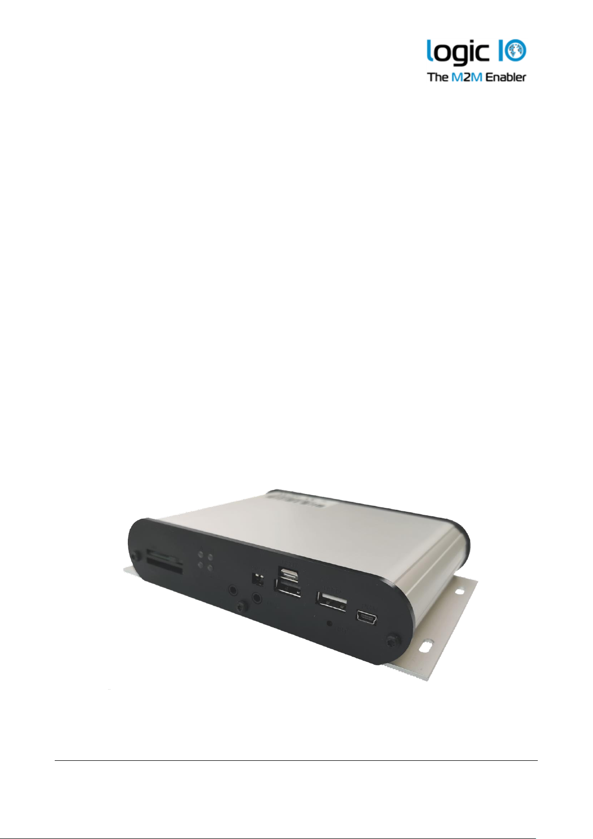
Technical Highlights
Platform:
➢ Based on the RTCU M2M Platform.
➢ NX32L (NX32 for Linux) execution architecture.
▪ RTCU IDE development tool.
▪ Operates under a full and highly optimized Linux variant.
▪ Open and extendable with Platform SDK.
Hardware Core:
➢ Cortex-A5 32-bit ARM processor operating at 500 Mhz.
➢ Hardware floating-point and DSP instructions.
➢ 128 MByte LP-DDR RAM.
➢ 512 MByte NAND Flash (file-system).
➢ 16 MByte NOR flash (system boot).
➢ 8 MB Dataflash (persistent memory/datalogger).
➢ 128 KB SRAM with battery back-up (unlimited endurance).
➢ Real-time clock with battery back-up.
Security:
➢ Embedded firewall.
➢ TLS/SSL support with full certificate management.
➢ TLS/SSL support for all major TCP protocols, such as SMTP, MQTT, and sockets.
➢ Hardware assisted encryption/authentication: AES-128, AES-192, AES-256, DES, TripleDES, HASH,
RND and RSA signature.
Wireless Communication:
➢ Worldwide LTE Cat. 4 Multi-Band Cellular Engine.
➢ Dual SIM-card readers and support for eSIM.
➢ Wireless LAN (Wi-Fi).
➢ Classic and Low-Energy Bluetooth.
➢ Multi-constellation GNSS with GPS, GLONASS, and GALILEO.
➢ Optional: GNSS with Dead Reckoning.
Wired Communication:
➢ 100 Mbps Ethernet LAN interface.
➢ 2 x full CAN 2.0B controller with hardware filtering and multi-speed support.
➢ 1-Wire bus for accessories such as ID-button reader, temperature sensors, etc.
➢ 2 x USB host port for expandability.
➢ 2 x RS232 channels and 1 x RS485 channels.
I/O Interfaces:
➢ 5 x digital inputs and 4 x high-power solid-state digital outputs.
➢ 4 x flex inputs with dual-mode analog /digital operation.
➢ 2 x analog inputs with 12 bits resolution.
➢ Expandable I/O with standard Modbus modules.
Page 8
RTCU NX-200 Technical Manual V1.00
Advanced Automotive M2MI/IoT Gateway
Logic IO ApS. Ph: (+45) 7625 0210
Holmboes Allé 14 Fax: (+45) 7625 0211
8700 Horsens Page 8 of 45 Email: [email protected]
Denmark www.logicio.com
User Interaction:
➢ High-speed Mini-USB service-port connector.
Audio:
➢ Fully digitized audio system.
➢ Transfer, store, and play audio.
➢ Amplified speaker output.
➢ Microphone input.
➢ Digitized cellular audio.
➢ DTMF support for Interactive Voice Response applications.
Storage:
➢ Internal flash drive with up-to 512 MByte capacity.
➢ Persistent memory and circular datalogger.
➢ Standard SD-CARD reader.
➢ USB flash media.
Power and Battery:
➢ Operating voltage from 8 to 36VDC.
➢ Onboard 2.6 Ah Li-Ion battery with intelligent charging.
Encapsulation:
➢ Exclusive and durable aluminum encapsulation.
Regulatory Approvals:
➢ 2007/46/EC UN ECE R10 Rev. 05 (E1).
➢ 2014/53/EU Radio Equipment Directive.
➢ 2011/65/EU RoHS Directive.
Page 9
RTCU NX-200 Technical Manual V1.00
Advanced Automotive M2MI/IoT Gateway
Logic IO ApS. Ph: (+45) 7625 0210
Holmboes Allé 14 Fax: (+45) 7625 0211
8700 Horsens Page 9 of 45 Email: [email protected]
Denmark www.logicio.com
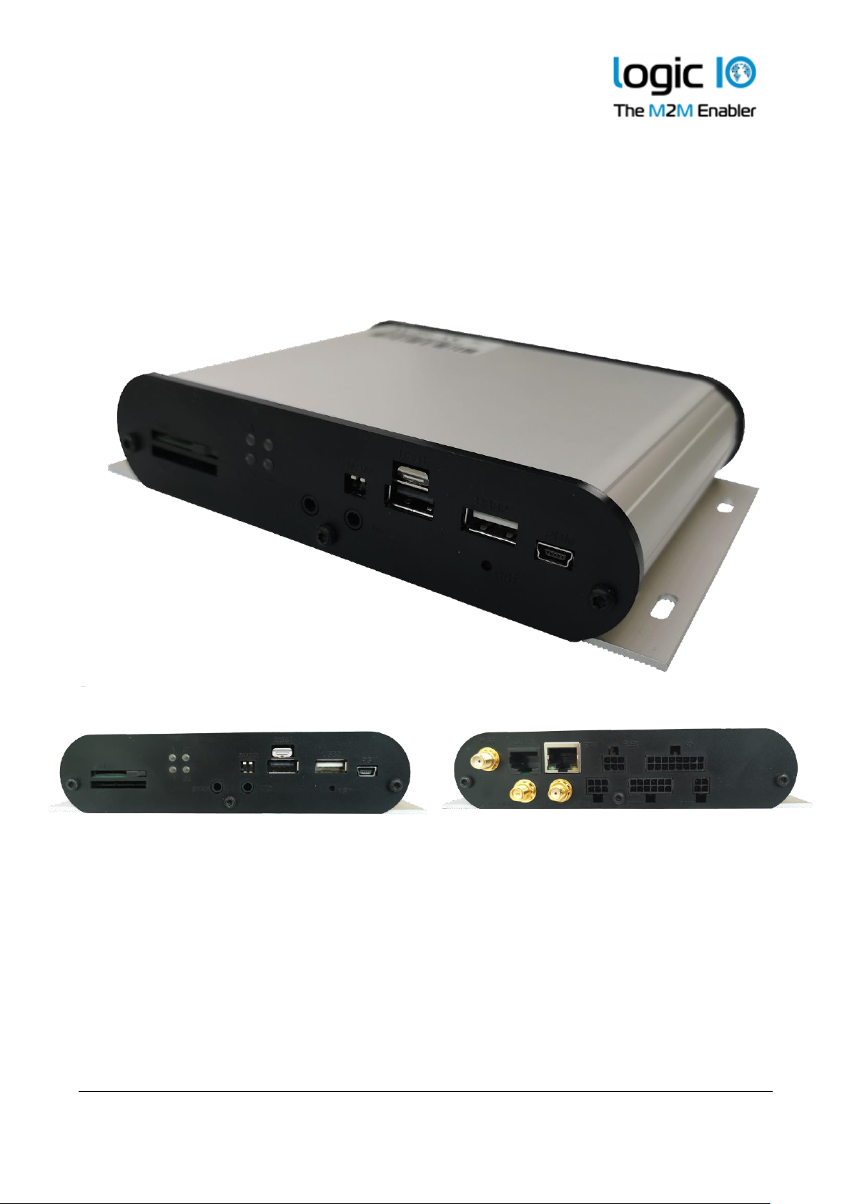
Graphical overview:
Page 10
RTCU NX-200 Technical Manual V1.00
Advanced Automotive M2MI/IoT Gateway
Logic IO ApS. Ph: (+45) 7625 0210
Holmboes Allé 14 Fax: (+45) 7625 0211
8700 Horsens Page 10 of 45 Email: [email protected]
Denmark www.logicio.com
External connections
Overview
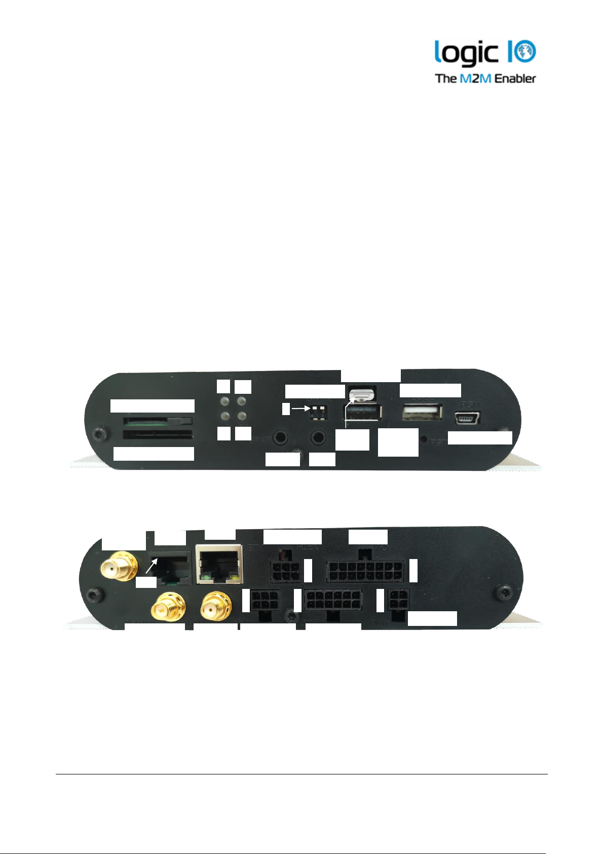
Connections to external equipment are made via the connectors that are located on the back and
front sides of the product.
The front panel is equipped with connectors commonly accessed by the user: SIM-Card, SD-Card,
DIP-Switches, audio input and output, LEDs, dual USB host ports, and USB slave service port.
The back panel holds all connectors necessary for installation: 4-pin (X1) power and ignition, 6-pin
(X4) for RS232 and CAN (channel 2), 12-pin (X2) for different communications interfaces, 16-pin
(X3) for analog and digital I/O, and 6-pin (X5) flex-inputs.
A graphical overview of the front- and back are shown below:
Front-side view
Back-side view
SIM card reader
SD card reader
DIP-Switch
1
USB Host 1
USB Host 2
MIC
SPKR
System
Switch
USB Service
A
B
S1
S2
Locking
Tab
WLAN/BT
antenna
Cell
antenna
SER2
ETH
X5: FLXIN
X1: PWR
X4: COM2
X2: COM1
X3: I/O
9
1
4
1
1
3
1
7
1
4
GNSS
antenna
Pin 1
Page 11
RTCU NX-200 Technical Manual V1.00
Advanced Automotive M2MI/IoT Gateway
Logic IO ApS. Ph: (+45) 7625 0210
Holmboes Allé 14 Fax: (+45) 7625 0211
8700 Horsens Page 11 of 45 Email: [email protected]
Denmark www.logicio.com
Signal Overview
X4: COM2
RD1
4 1 TD1
SGND
5 2 CAN2-H X5: FLXIN
SGND
6 3 CAN2-L
AGND
3 6 AGND
FLXIN3
2 5 FLXIN4
FLXIN1
1 4 FLXIN2
X2: COM1
1-WIRE LED
7 1 1-WIRE
SGND
8 2 SGND
X3: I/O
CAN1-L
9 3 CAN1-H
AIN2
8
16
AGND
SGND
10 4 NC
AIN1
7
15
AGND
SGND
11 5 RS485+
DIN5
6
14
SGND
DC-Out
12 6 RS485-
DIN3
5
13
DIN4
SGND
4
12
SGND
DIN1/IGN
3
11
DIN2
DOUT3
2
10
DOUT4
X1: PWR
DOUT1
1 9 DOUT2
SUPPLY
3 1 SUPPLY
PGND
4 2 D1/IGN
Page 12
RTCU NX-200 Technical Manual V1.00
Advanced Automotive M2MI/IoT Gateway
Logic IO ApS. Ph: (+45) 7625 0210
Holmboes Allé 14 Fax: (+45) 7625 0211
8700 Horsens Page 12 of 45 Email: [email protected]
Denmark www.logicio.com
Connector X1: 4 pin PWR connector overview
Pin
Name
Description
1
SUPP
Power supply, positive (+) connection
2
DI1/IGN
Digital input 1 / Ignition input (Shared with X3)
3
SUPP
Power supply, positive (+) connection
4
PGND
Power Ground
Connector X2: 12 pin COM1 connector overview
Pin
Name
Description
1
1Wire
1-Wire bus
2
SGND
Signal Ground
3
CAN1-H
CAN-bus channel 1 H-signal
4
NC
Internally not connected
5
RS485+
RS485 non-inverting signal
6
RS485-
RS485 inverting signal
7
1W-LED
1-Wire ID-Button LED
8
SGND
Signal Ground
9
CAN1-L
CAN-bus channel 1 L-signal
10
SGND
Signal Ground
11
SGND
Signal Ground
12
DC-OUT
5V/500mA DC-Out for external equipment
Connector X3: 16 pin I/O connector overview
Pin
Name
Description
1
DOUT1
Digital output 1
2
DOUT3
Digital output 3
3
DIN1/IGN
Digital input 1 / Ignition input (Shared with X1)
4
SGND
Signal Ground
5
DIN3
Digital input 3
6
DIN5
Digital input 5
7
AIN1
Analog input 1
8
AIN2
Analog input 2
9
DOUT2
Digital output 2
10
DOUT4
Digital output 4
11
DIN2
Digital input 2
12
SGND
Signal Ground
13
DIN4
Digital input 4
14
SGND
Signal Ground
15
AGND
Analog Ground
16
AGND
Analog Ground
Page 13
RTCU NX-200 Technical Manual V1.00
Advanced Automotive M2MI/IoT Gateway
Logic IO ApS. Ph: (+45) 7625 0210
Holmboes Allé 14 Fax: (+45) 7625 0211
8700 Horsens Page 13 of 45 Email: [email protected]
Denmark www.logicio.com
Connector X4: 6 pins COM2 connector overview
Pin
Name
Description
1
TD
Transmit Data from serial port 1, RS232 compatible
2
CAN2-H
CAN-bus channel 2 H-signal
3
CAN2-L
CAN-bus channel 2 L-signal
4
RD
Receive Data for serial port 1, RS232 compatible
5
SGND
Signal Ground
6
SGND
Signal Ground
Connector X5: 6 pins FLXIN connector overview
Pin
Name
Description
1
FLXIN1
Flex input 1
2
FLXIN3
Flex input 3
3
AGND
Analog Ground
4
FLXIN2
Flex input 2
5
FLXIN4
Flex input 4
6
AGND
Analog Ground
Connector SER2: RJ45 connector overview, fully RS232 compatible
Pin
Name
Description
1
DSR
Data Set Ready
2
DCD
Data Carrier Detect
3
DTR
Data Terminal Ready
4
SGND
Signal Ground
5
RD
Receive Data for serial port 2
6
TD
Transmit Data from serial port 2
7
CTS
Clear To Send
8
RTS
Request To Send
Page 14

RTCU NX-200 Technical Manual V1.00
Advanced Automotive M2MI/IoT Gateway
Logic IO ApS. Ph: (+45) 7625 0210
Holmboes Allé 14 Fax: (+45) 7625 0211
8700 Horsens Page 14 of 45 Email: [email protected]
Denmark www.logicio.com
Accessories for cable assembly.
Order-code
Name
RT-O-TYCO-H4
TYCO p/n: 794617-4
Tyco, Connector house 4 pins. Bag with 10 pcs
RT-O-TYCO-H6
TYCO p/n: 794617-6
Tyco, Connector house 6 pins. Bag with 10 pcs
RT-O-TYCO-H12
TYCO p/n: 1-794617-2
Tyco, Connector house 12 pins. Bag with 10 pcs
RT-O-TYCO-H16
TYCO p/n: 1-794617-6
Tyco, Connector house 16 pins. Bag with 10 pcs
RT-O-TYCO-CR
TYCO p/n: 794606-1
Tyco, Crimp Contacts for connector house. Wire size 0.2 to 0.5 mm2.
Bag with 100 pcs.
RT-O-TYCO-TOOL
TYCO p/n: 91501-1
Tyco, Crimp hand tool for easy assembly of TYCO crimp contacts.
Wire size 0.2 to 0.5 mm2
Recommended tool:
Alternative tools:
Tyco 91501-1 (0.20 to 0.50mm2) RS 495-9675, Farnell 1111475
Tyco 91502-1 (0.05 to 0.15mm2) RS 495-9675, Farnell 1111476
Extraction tool:
Tyco 843996-6 extraction tool. RS 495-9704, Farnell 1111477
Connector Mini USB-B
The USB port is for programming and communication with the RTCU IDE (RACP compliant
application). A standard USB cable with a connector length of 10mm on the USB-B end can be used
between the device and the PC
Connector Ethernet
This is a standard 10Base-T/100Base-TX IEEE 802.3 compliant Ethernet connector. Please use an
appropriate connector and cable, such as a standard CAT-5 twisted pair patch cable
Connector USB-Host
These are standard full-speed USB-A host port connectors and used for communication with
accessories connected to the host port. These ports are supplied internally, and current
consumption is limited to 500mA
Page 15

RTCU NX-200 Technical Manual V1.00
Advanced Automotive M2MI/IoT Gateway
Logic IO ApS. Ph: (+45) 7625 0210
Holmboes Allé 14 Fax: (+45) 7625 0211
8700 Horsens Page 15 of 45 Email: [email protected]
Denmark www.logicio.com
Power supply
The RTCU NX-200 device must be supplied with 8..36 VDC from an external DC power source
connected to the 4 pin power connector. Positive power is applied to the SUPP pin, and the ground
is connected to the PGND pin.
The connector has two “SUPP” supply pins as these also supplies power to the digital outputs. If
the total current consumption on the digital outputs exceeds 1.5A, then power must be applied to
both pins. Otherwise, one pin is sufficient.
There are three different labels for the ground connections: Power Ground (PGND), Signal Ground
(SGND) and Analog Ground (AGND). The signal and analog grounds are filtered from the power
ground. Power ground must only be used as a power supply return path. The signal ground is
used as a ground reference for digital I/O’s and serial interfaces, and the analog ground is used as
a low noise analog ground reference for the analog inputs.
The RTCU NX-200 is protected against wrong polarity. If a chassis or system grounds are
connected to either SGND or AGND, a wrong polarity on the supply lines will destroy the internal
GND connection. For the avoidance of such a scenario, a fuse can be installed on the positive
supply.
The RTCU also contains an internal high capacity backup battery that will supply the RTCU, if the
external power supply should fail or be disconnected. By default, the RTCU is powered down
when a power failure occurs. This setting, however, can be changed. Please consult the RTCU IDE
documentation for additional information.
Disabling the external DC power from the application interface and forcing the device to operate
on the internal backup battery is supported. Please consult the RTCU IDE documentation for
additional information.
When the ignition input is activated with a logical high, the RTCU device will wake-up if it was in
power-down mode. The ignition input (digital input 1) is available on the power connector to
minimize the need for connectors in minimal installations, but it is also available on the X3
connector (digital I/O and analog Inputs) - only one should be used at a time.
X1: 4 pin PWR connector overview.
Pin
Name
Description
1
SUPP
Power supply, positive (+) connection
2
DI1/IGN
Digital input 1 / Ignition input (Shared with 16 pin connector)
3
SUPP
Power supply, positive (+) connection
4
PGND
Power Ground
Page 16
RTCU NX-200 Technical Manual V1.00
Advanced Automotive M2MI/IoT Gateway
Logic IO ApS. Ph: (+45) 7625 0210
Holmboes Allé 14 Fax: (+45) 7625 0211
8700 Horsens Page 16 of 45 Email: [email protected]
Denmark www.logicio.com
Digital outputs
The digital outputs control four “high-side” switches. They function like a contact, where one side
is connected to the positive supply of the RTCU unit, and the other is the output. The switches are
protected against short circuit, ESD and electronic kickback from inductive loads such as relays,
etc. The maximum switch-able inductance is 20mH and must not be exceeded.
The digital outputs are supplied through the X1 power connector that also supplies the rest of the
RTCU unit. As this power is also the RTCU NX-200 main power, a power-fail would also affect
the digital outputs.
The RTCU unit offers a very advanced power management that makes it possible to have one or
more outputs enabled while the RTCU is in low power mode. Please consult the RTCU IDE
documentation for additional information.
X3: 16 pin I/O connector overview.
Pin
Name
Description
1
DOUT 1
Digital output 1
9
DOUT 2
Digital output 2
2
DOUT 3
Digital output 3
10
DOUT 4
Digital output 4
Specification for each digital output
Type
Min.
Max.
Unit
Solid state
5.5
36
VDC
Short-circuit, Overload, Overvoltage, ESD,
Inductive kick-back protected up to 20mH (single pulse).
-
1.5
A -
280
mΩ
On-state resistor per channel
Please note: Special attention to wiring must be taken; if the total current consumption of the
digital outputs exceeds 1.5A, then PGND must be used as a return path for the output(s).
If the total current consumption of the digital outputs exceeds 5A, the two SUPP pins and PGND
must be used for supply.
Page 17
RTCU NX-200 Technical Manual V1.00
Advanced Automotive M2MI/IoT Gateway
Logic IO ApS. Ph: (+45) 7625 0210
Holmboes Allé 14 Fax: (+45) 7625 0211
8700 Horsens Page 17 of 45 Email: [email protected]
Denmark www.logicio.com
Digital Inputs / Ignition Input
The digital inputs are all low pass filtered and transient protected. To activate the inputs, connect a
positive voltage between the input and the GND connector.
Please note: The DIN 1/IGN input is special as it also functions as the ignition input. If the ignition
input is activated with a logically high or low (Wait For Event mode only), when the RTCU is in
low power mode, it will wake-up the unit. A power apply will also wake-up the unit, if it is in
power-down mode or WaitForEvent mode with power Apply and/or ignition selected for wakeup. The ignition is de-bounced with a period between 1-2 ms, when used as a digital input. So, any
logical level applied to this input must be greater than 2 ms to be valid. The DIN 1/IGN input is
available on both the X1 power connector and the X3 connector together with the other digital
inputs – only one should be used at a time.
The power management allows the possibility to configure a wake-up on one or more digital
inputs with individually configured falling- or rising edge detection. Please consult the RTCU IDE
documentation for additional information.
X3: 16 pin I/O connector overview.
Pin
Name
Description
3
DIN 1/IGN
Digital input 1 / Ignition input. (Shared with X1)
11
DIN 2
Digital input 2
5
DIN 3
Digital input 3
13
DIN 4
Digital input 4
6
DIN5
Digital input 5
4
SGND
Signal Ground
12
SGND
Signal Ground
14
SGND
Signal Ground
Specification for each digital input:
Min.
Typ.
Max.
Unit
Logic “High”
8
12
40
VDC
Protected against transients and
low-pass filtered
Logic “Low”
-5 - 3
VDC
Cut-off frequency
-
25 - kHz
Input impedance
-
14 - kΩ
Page 18
RTCU NX-200 Technical Manual V1.00
Advanced Automotive M2MI/IoT Gateway
Logic IO ApS. Ph: (+45) 7625 0210
Holmboes Allé 14 Fax: (+45) 7625 0211
8700 Horsens Page 18 of 45 Email: [email protected]
Denmark www.logicio.com
Analog Inputs
The analog inputs are voltage inputs specified with an operating range of 0V to 10V DC. The
conversion resolution is up to 12 bit (0..4095). Please consult the RTCU IDE documentation for
further details.
The input signal is connected between AINx and AGND. AGND must be connected to the
reference of the connected equipment. Please be aware that deviations may occur, as the system is
very noise sensitive. Avoid long unshielded wires, and large fast-changing signals routed parallel
to the analog signals.
The inputs are low-pass filtered, ESD- and transient protected.
X3: 16 pin I/O connector overview.
Pin
Name
Description
7
AIN 1
Analog input 1
8
AIN 2
Analog input 2
15
AGND
Analog Ground
16
AGND
Analog Ground
Specification for each analog input:
Min.
Typ.
Max.
Unit
0 - 10
VDC
Protected against transients and
low-pass filtered
Precision is based on
measurements @ 25 ˚C
Resolution
- - 12
Bit
Precision
-
0.15
0.3
%FSR
Cut-off frequency
-
4.5 - kHz
Input impedance
-
40 - kΩ
Page 19
RTCU NX-200 Technical Manual V1.00
Advanced Automotive M2MI/IoT Gateway
Logic IO ApS. Ph: (+45) 7625 0210
Holmboes Allé 14 Fax: (+45) 7625 0211
8700 Horsens Page 19 of 45 Email: [email protected]
Denmark www.logicio.com
Flex Inputs
The flex inputs are multi-mode inputs that can be configured to operate as either analog or as
digital inputs. The operating range is from 0V to 30V DC and is configurable as digital inputs with
customized threshold values.
The flex inputs can also be used as digital inputs, either behaving the same way as the normal
digital inputs with the same threshold values or by using different threshold values for more
advanced features.
The same flex input can be used for multiple digital inputs with different settings, e.g., different
threshold values or debounce timing.
Configuring the flex input for band matching allows triggering the digital inputs at specific values,
making it possible to connect circuits that generate different voltages for different states and then
read the state directly.
An example could be using switches and resistors to create an R2R ladder that allows for
connecting multiple switches to a single flex input.
See the RTCU IDE documentation for more details about how to configure the flex inputs as digital
inputs.
The input signal is connected between FLXINx and AGND. AGND must be connected to the
reference of the connected equipment. Please be aware that deviations may occur, as the system is
very noise sensitive. Avoid long unshielded wires, and large fast-changing signals routed parallel
to the analog signals.
The inputs are low-pass filtered, ESD- and transient protected.
X5: 6 pin FLXIN connector overview
Pin
Name
Description
1
FLXIN1
Flex input 1
4
FLXIN2
Flex input 2
2
FLXIN3
Flex input 3
5
FLXIN4
Flex input 4
3
AGND
Analog Ground
6
AGND
Analog Ground
Page 20

RTCU NX-200 Technical Manual V1.00
Advanced Automotive M2MI/IoT Gateway
Logic IO ApS. Ph: (+45) 7625 0210
Holmboes Allé 14 Fax: (+45) 7625 0211
8700 Horsens Page 20 of 45 Email: [email protected]
Denmark www.logicio.com
Specification for each flex input:
Min.
Typ.
Max.
Unit
0 - 30
VDC
Protected against transients and
low-pass filtered
Precision is based on
measurements @ 25 ˚C
Resolution
- - 12
Bit
Precision
-
0.4
0.5
%FSR
Cut-off frequency
-
4.5 - kHz
Input impedance
-
120 - kΩ
Page 21

RTCU NX-200 Technical Manual V1.00
Advanced Automotive M2MI/IoT Gateway
Logic IO ApS. Ph: (+45) 7625 0210
Holmboes Allé 14 Fax: (+45) 7625 0211
8700 Horsens Page 21 of 45 Email: [email protected]
Denmark www.logicio.com
CAN communication port
The RTCU provides the physical layer for the CAN (Controller Area Network) serial
communication interface in accordance with the ISO 11898 standard. The CAN bus is designed for
high-speed (up to 1Mbit) robust communication in especially harsh environments like those found
in the automotive industry.
The CAN interface can be connected to an existing CAN network with a common protocol like the
J1939 standard, to retrieve information for surveillance or information purposes. The interface can
also be used as a robust serial data link with a non-standard protocol. Please consult the RTCU IDE
documentation for more information.
The physical layer consists of a two-wire (CAN-H and CAN-L) differential bus and a signal
ground for reference.
If the RTCU is connected to a “non-existing” network, a 120 ohm resistor must be connected
between CAN-H and CAN-L on each end of the transmission line in order to terminate it and
avoid signal reflections. This resistor can be connected by activating the software jumper in the
user application. Please consult the RTCU IDE document for the software jumper for a detailed
description.
Be aware that connecting the RTCU to a CAN network can be dangerous. If the RTCU is not
configured with the correct network parameters, it will lead to network corruption and may
interfere with other connected equipment on the bus. Especially in vehicles, great precautions
must be observed to prevent communication interruptions.
By default, the write capability on the CAN bus channel 1 is disabled. This can be enabled by the
jumper that is located at the front-side of the device.
By default, the write capability on the CAN bus channel 2 is enabled and it is not possible to
disable
A wide range of software functions is available for easy access to the network. Please consult the
RTCU IDE documentation for further information.
X2: 12 pin COM1 connector overview.
Pin
Name
Description
3
CAN1-H
CAN-bus channel 1 H-signal
9
CAN1-L
CAN-bus channel 1 L-signal
8
SGND
Signal Ground
X4: 6 pin COM1 connector overview.
Pin
Name
Description
2
CAN2-H
CAN-bus channel 2 H-signal
3
CAN2-L
CAN-bus channel 2 L-signal
6
SGND
Signal Ground
Page 22
RTCU NX-200 Technical Manual V1.00
Advanced Automotive M2MI/IoT Gateway
Logic IO ApS. Ph: (+45) 7625 0210
Holmboes Allé 14 Fax: (+45) 7625 0211
8700 Horsens Page 22 of 45 Email: [email protected]
Denmark www.logicio.com
RS232 port 1
This port can be used as a general-purpose RS232 serial port and does not support handshaking.
This port can also be used for communication with the RTCU accessories.
X4: 6 pin SER1 connector overview.
Pin
Name
Description
1
TD
Transmit Data from serial port 1, RS232 compatible
4
RD
Receive Data for serial port 1, RS232 compatible
5
SGND
Signal Ground
RS232 port 2
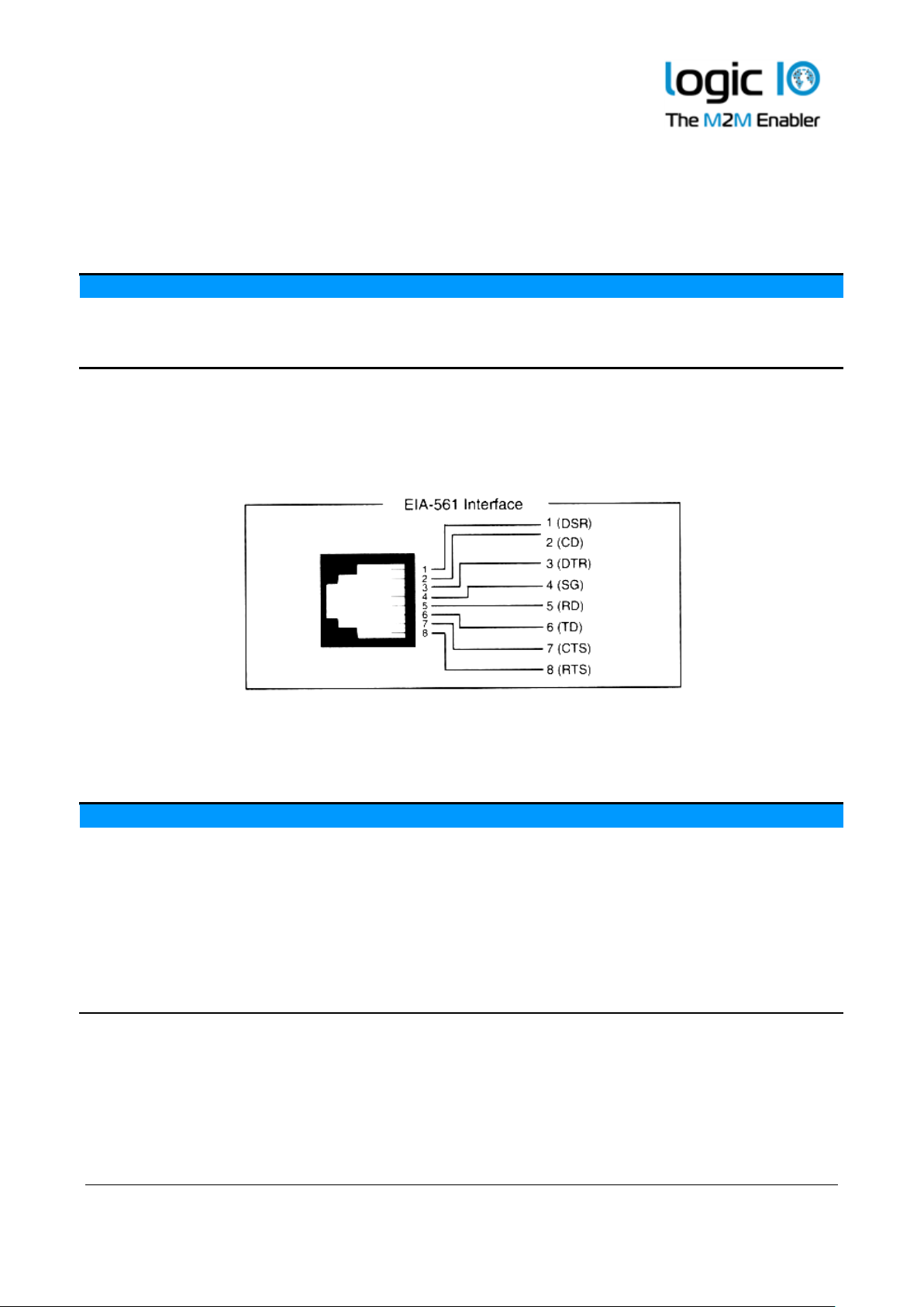
The port is a general-purpose RS232 port with all control signals according to EIA-561 which
defines RS232 on a modular connector.
The signals are available on the RJ-45 connector located on the top side of the RTCU NX-200
device.
Connector SER2: RJ-45 connector overview, fully RS232 compatible
Pin
Name
Description
1
DSR
Data Set Ready
2
DCD
Data Carrier Detect
3
DTR
Data Terminal Ready
4
GND
Signal Ground
5
RD
Receive Data for serial port 2
6
TD
Transmit Data from serial port 2
7
CTS
Clear To Send
8
RTS
Request To Send
Page 23
RTCU NX-200 Technical Manual V1.00
Advanced Automotive M2MI/IoT Gateway
Logic IO ApS. Ph: (+45) 7625 0210
Holmboes Allé 14 Fax: (+45) 7625 0211
8700 Horsens Page 23 of 45 Email: [email protected]
Denmark www.logicio.com
RS485 communication ports (EIA/TIA-485-A compatible)
RS485 is a multi-drop network with a maximum of 32 nodes connected simultaneously to the bus.
The RS485 bus contains an RS485+ ( also known as RS485 A, non-inverting) and an RS485- (also known
as RS485 B, inverting) signal as well as a signal ground which must always be connected to the
common signal ground for all nodes connected to the RS485 bus!
The maximum cable length for the RS485 bus is according to the EIA/TIA-485-A standard (max.
1000m @ <100kbit); this limit is highly influenced by the quality of the cable, signaling rate, noise
etc.
At longer cable lengths, noisy environments, or high communication speeds, it might be necessary
to terminate the transmission line with a 1201 ohm resistor at each end of the transmission line to
terminate it and avoid signal reflections. If the RTCU NX-200 is used as an endpoint node, the
software jumper for both RS485 ports separately can be activated through the user application in
order to terminate the RS485 communication lines with 120Ω.
By default, the RS485 communication lines are not terminated with 120 Ω. Please consult the RTCU
IDE documentation for further information on how to use the software jumpers.
Please note: For best performance, protection and noise immunity shielded cable advised to be
used to connect the device to the RS485 communications bus.
X2: 12 pin COM connector overview.
Pin
Name
Description
5
RS485+
RS485 non-inverting signal (A)
6
RS485-
RS485 inverting signal (B)
11
SGND
Signal Ground
1-Wire bus
The 1-Wire bus is available on the X2 connector. All 1-Wire communication goes through a single
connection, and all 1-Wire devices connected to this connection retrieves its power directly from
the bus (called parasitic power). For this, only two wires are needed – the 1-wire signal and the
ground reference – allowing minimal cable installations.
For 1-Wire ID-Button readers, which include a built-in LED, a dedicated output is available for this
purpose. Please consult the RTCU IDE documentation for further information.
2 Assuming use of a CAT5 twisted pair cable
Page 24
RTCU NX-200 Technical Manual V1.00
Advanced Automotive M2MI/IoT Gateway
Logic IO ApS. Ph: (+45) 7625 0210
Holmboes Allé 14 Fax: (+45) 7625 0211
8700 Horsens Page 24 of 45 Email: [email protected]
Denmark www.logicio.com
X2: 12 pin COM connector overview.
Pin
Name
Description
1
1Wire
1-Wire bus for ID-Button / Temperature sensor
7
1W-LED
1-Wire ID-Button LED
2
SGND
Signal Ground
DC-Out
A 5V DC output is available on the X2 connector. It is possible to control the output in order to
save power. The output is short circuit- (to ground), ESD- and transient protected. Make sure not
to exceed the current specification of the output and be aware that inrush currents of the external
equipment may exceed the specifications. It is recommended to install a fuse to protect the output.
This output must be enabled from the application. Please consult the RTCU IDE on-line manual for
more information.
X2: 12 pin COM connector overview.
Pin
Name
Description
12
DC-Out
+5V/500mA DC-Out for external equipment.
11
SGND
Signal Ground
Ethernet
The RTCU NX-200 offers an onboard IEEE 802.3 compatible 100BASE-T Ethernet MAC controller
and transceiver for communication with peripherals and back-end systems over standard Ethernet.
Please refer to the RTCU IDE documentation for details on the usage of this interface.
USB Host interface
The RTCU NX-200 offers two high-speed USB host ports on the standard USB A connector for
connection of various USB devices. The host port 1 connector includes locking latch that locks the
USB cable connector in position. To remove the USB cable, the locking tab needs to be pushed
slightly until the locking latch is released. The USB host ports can supply the external USB device
with up to 500mA each.
Please notice: To reduce the total power consumption then DC-Out, USB host 1 and USB host 2
can not be enabled at the same time. Only two out of these three interfaces can be simultaneously
enabled. Please consult the RTCI IDE online help for further information.
Audio interface
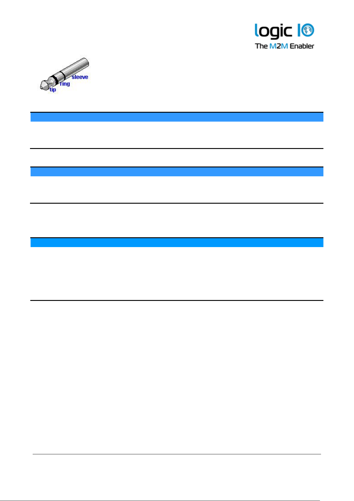
The audio interface is available on the three 3.5mm jack connectors on the front side of the device.
The audio interface includes a microphone input and speaker output.
Page 25
RTCU NX-200 Technical Manual V1.00
Advanced Automotive M2MI/IoT Gateway
Logic IO ApS. Ph: (+45) 7625 0210
Holmboes Allé 14 Fax: (+45) 7625 0211
8700 Horsens Page 25 of 45 Email: [email protected]
Denmark www.logicio.com
3 pin SPK Out
Pin
Name
Description
Tip
SPK_OUT_P
Differential speaker positive (+) output
Ring
SPK_OUT_N
Differential speaker negative (-) output
Sleeve
N.A.
Not connected internally
3 pin MIC In
Pin
Name
Description
Tip
MIC_BIAS
Bias voltage to the microphone
Ring
MIC_IN
Audio signal from the microphone
Sleeve
GND
Signal ground
The specifications on the audio interface connectors are as following:
Parameter
Min.
Typ.
Max.
Unit
Description
Impedance
4 - -
Ω
Output power
- - - - 2.1
1.4
W W @ 4 ohm 50pF load
@ 8 ohm 50pF load
Headphone impedance
16 - -
Ω
AC coupled
Full -scale input voltage
- - 0.74
Vrms
Mic. bias voltage
-
2.5
-
V
±10%
Page 26
RTCU NX-200 Technical Manual V1.00
Advanced Automotive M2MI/IoT Gateway
Logic IO ApS. Ph: (+45) 7625 0210
Holmboes Allé 14 Fax: (+45) 7625 0211
8700 Horsens Page 26 of 45 Email: [email protected]
Denmark www.logicio.com
3D movement sensor
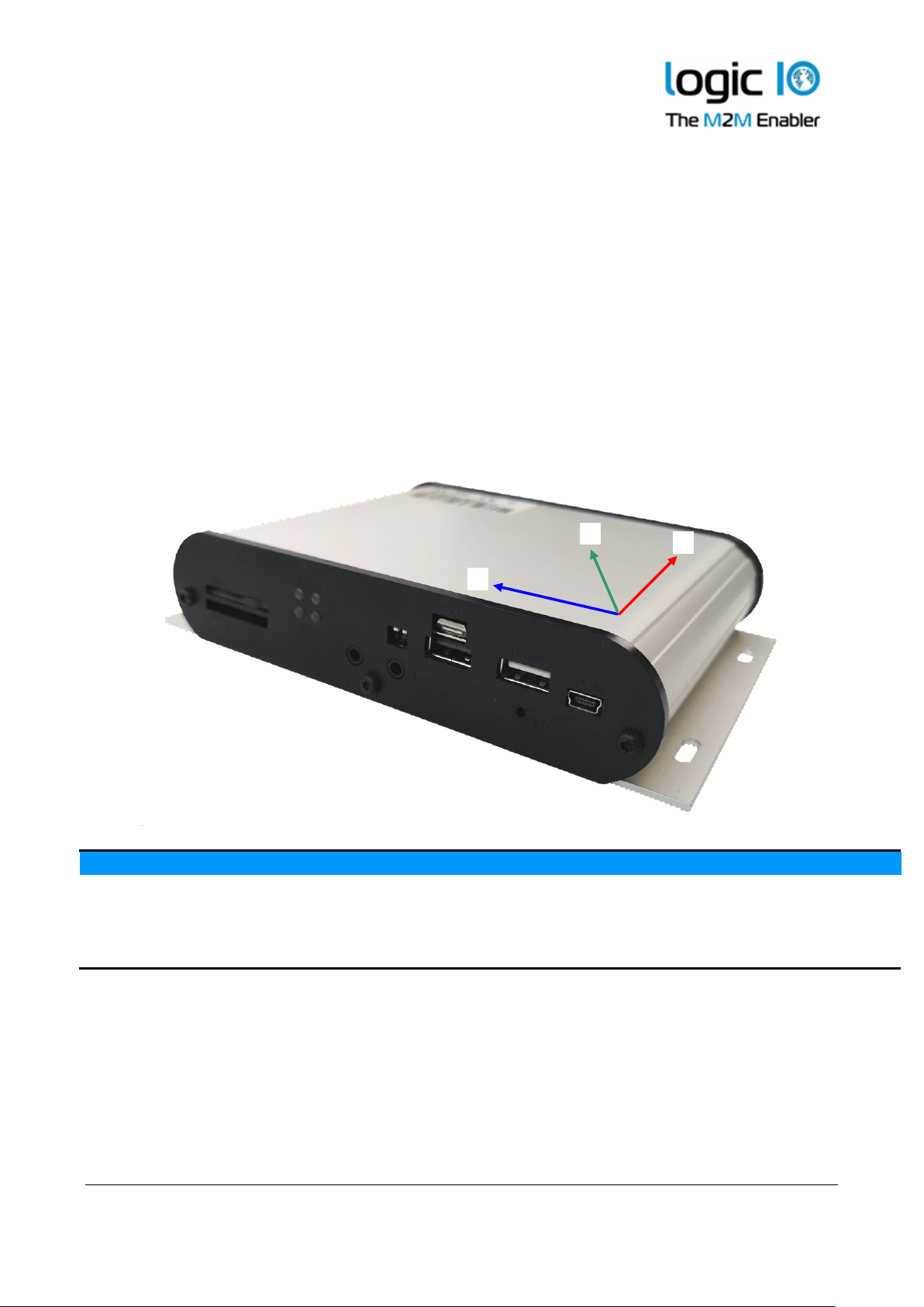
The RTCU NX-200 device contains a 3-axis accelerometer, 3-axis gyroscope, and 3-axis
magnetometer in order to detect vibration and motion. This sophisticated range of movement
sensors allows to detect movement and position change in 3 directions, X-Y-Z with a force as high
as 16g in acceleration, 2000 dps in rotation and 50 gauss in magnetic field. The simplest use is with
the power management detecting when the vehicle is moved and the most advanced analytical
applications such as driving behavior/eco-driving.
Please consult the RTCU IDE documentation for more detailed information.
The positions of the 3-axis are as following:
Specification:
Unit
Resolution
Accelerometer
±16
g
The acceleration can be set as relative to motion,
or relative to earth gravity
Gyroscope
±2000
dps Magnetometer
±50
gauss
+X
+Z
+Y
Page 27

RTCU NX-200 Technical Manual V1.00
Advanced Automotive M2MI/IoT Gateway
Logic IO ApS. Ph: (+45) 7625 0210
Holmboes Allé 14 Fax: (+45) 7625 0211
8700 Horsens Page 27 of 45 Email: [email protected]
Denmark www.logicio.com
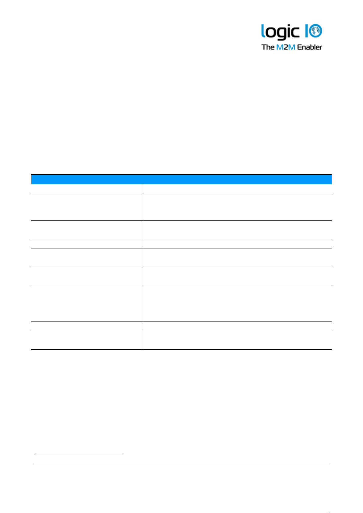
LED Indicators
Four bi-colored (red and green) LED indicator is present on the front of the device (see graphical
overview).
Two bi-colored LED’s (A and B) are available to the user, and the remaining two LED’s (S1 and S2)
are signaling the status and possible errors of the RTCU device.
User LED A and B
LED A and B are composed of four individually controllable LEDs:
• LED named A on the front consists of LED 1 (green) and LED 2 (red).
• LED named B on the front consists of LED 3 (green) and LED 4 (red).
They are easily accessed from within the application program, and it is possible to mix the LED’s
to obtain a third color: yellow. Please consult the RTCU IDE documentation for more information.
Page 28
RTCU NX-200 Technical Manual V1.00
Advanced Automotive M2MI/IoT Gateway
Logic IO ApS. Ph: (+45) 7625 0210
Holmboes Allé 14 Fax: (+45) 7625 0211
8700 Horsens Page 28 of 45 Email: [email protected]
Denmark www.logicio.com
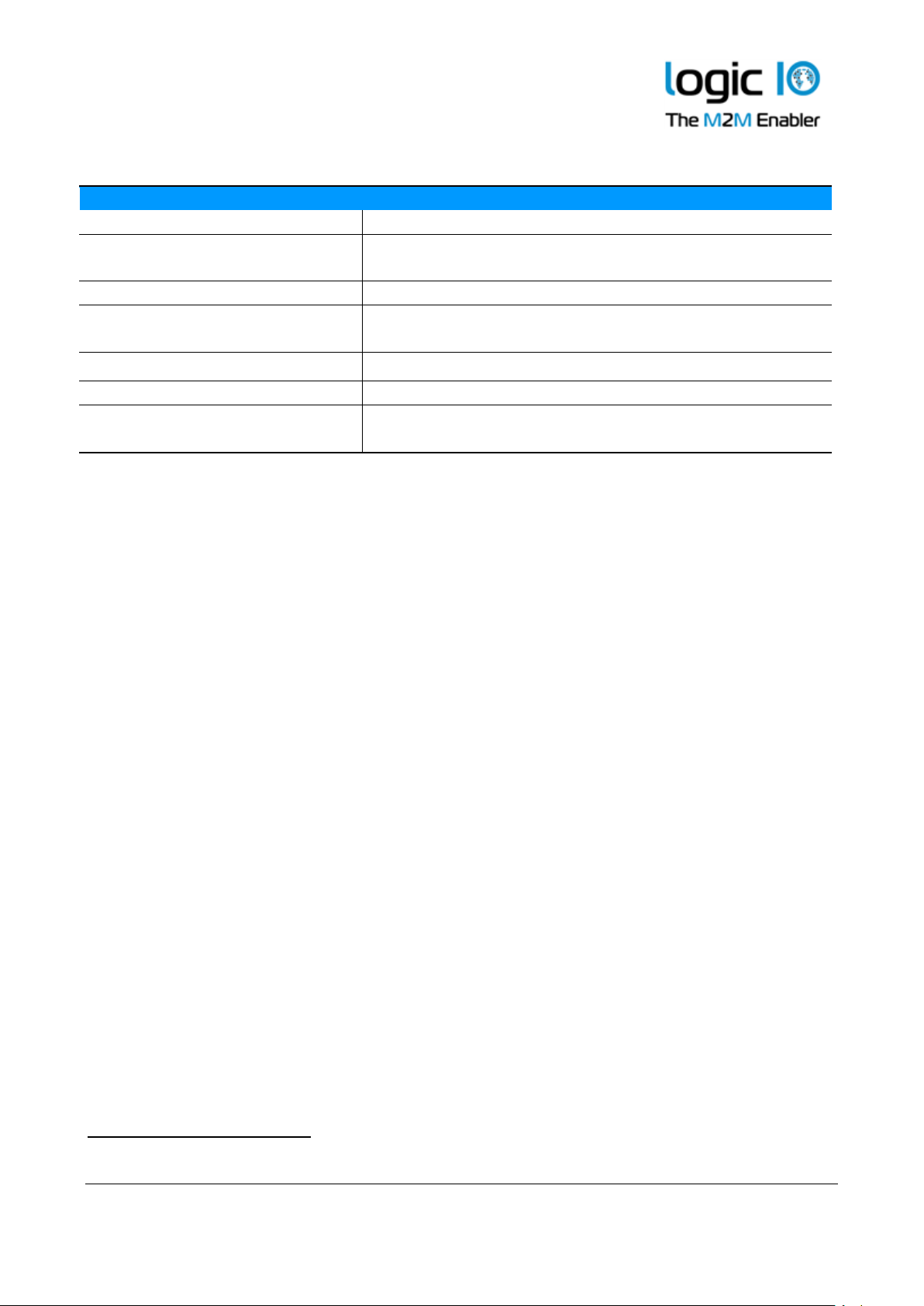
System LED S1 and S2
The RTCU is equipped with two system LED’s, which shows the status and possible errors of the
RTCU device.
The different patterns are listed in the table below. If the color of the system LED S1 is yellow, the
device is actively communicating with the RTCU IDE (or another program, supporting the RTCU
RACP protocol).
The LED S2 is signaling either the cellular module activity or if all other LED’s are off, that the
RTCU is in the “wait for event” low power state.
S1: System LED1 pattern overview
Pattern
Description
Fastest blinking, green
The device is initializing, preparing to start the application.
Fast blinking, green
S2 On, green
The device is installing an update. Depending on the kind of
update, it may take some time. The progress can also be
observed on the display.
Fast blinking, green1
The device has been forced into recovery mode with the use
of the system switch. The application is not executing.
500ms On / 500ms Off green2
The device is executing the application program
1.5s On / 0.5s Off. green2
The device is executing the application program, while
charging the internal back-up battery.
Fast blinking, red2
A runtime error has been detected in the program.
Use the RTCU IDE to obtain the fault log.
Alternating Fast/Slow, red2
The device has lost its firmware! This can only happen if,
during a firmware upgrade, the RTCU device loses power or
the communication is lost completely. In this case, simply
upload the firmware to the device again.
75ms On / 925ms Off, green
Execution speed is different from full-speed.
On yellow (and all other LEDs
OFF)
The device is booting, initializing the system
3 Or yellow when communicating with the RTCU IDE or another program, supporting the RTCU RACP protocol).
Page 29
RTCU NX-200 Technical Manual V1.00
Advanced Automotive M2MI/IoT Gateway
Logic IO ApS. Ph: (+45) 7625 0210
Holmboes Allé 14 Fax: (+45) 7625 0211
8700 Horsens Page 29 of 45 Email: [email protected]
Denmark www.logicio.com
S2: System LED2 pattern overview (Cellular activity and “Wait For Event”)
Pattern
Operating Status
Off
The cellular engine is turned off
600 ms On / 600 ms Off green
Missing SIM card or PIN code.
Network search and logon in progress.
75 ms On / 3 s Off green
Logged on to the network.
75 ms On / 75 ms Off /
75 ms On / 3 s OFF green
A Packet/GPRS session is active.
Flashing green
Indicates Packet/ GPRS data transfer.
On green (and all other LEDs OFF)
The system is booting into recovery mode
10 s OFF / 50 ms ON green
(and all other LEDs OFF)
The RTCU device is in low-power “Wait For Event” state.
Switches
DIP-switch
The RTCU NX-200 device contains two dip-switches. The dip switches are located on the front side
of the device for easy user access (see graphical overview).
System switch (RST)
The RTCU NX-200 device contains a combined reset/diagnostic switch. This switch is accessible
from the front of the unit (see graphical overview). It is necessary to use a small thin object with a
diameter of approx. 2 mm, for example, a straightened-out paper clip for this purpose.
By activating the switch shortly, the RTCU device will do a complete reset as if the power was
removed and reapplied.
If the reset switch is held down for approx. 3 seconds1 the device will instead enter recovery mode2
where the application will not be started. In recovery mode, the system will automatically turn on
any communication channel and establish a connection to the RTCU Gateway (if configured).
Pressing reset will also activate the device when in power-down mode. If external power is
removed and the backup battery is disabled, the reset switch can still be used to boot into recovery
mode, as long as there is enough power left on the battery.
5 System LED S2 will flash green three times when this state is entered.
6 System LED S1 will indicates this state by fast blinking green or yellow.
Page 30

RTCU NX-200 Technical Manual V1.00
Advanced Automotive M2MI/IoT Gateway
Logic IO ApS. Ph: (+45) 7625 0210
Holmboes Allé 14 Fax: (+45) 7625 0211
8700 Horsens Page 30 of 45 Email: [email protected]
Denmark www.logicio.com
Internal Li-Ion battery
The RTCU contains an internal Li-Ion battery for operation even when the external power is
absent, making it possible to report power loss etc. Please note that when external power is
removed, the device will be powered down by default. This setting can be changed as documented
in the RTCU IDE documentation.
The analog outputs will be disabled when power failure occurs as the internal battery cannot
provide the supply voltage needed.
The battery charging is completely automated and handled internally by the RTCU device –
leaving no need for user interaction. Different kinds of functions (Battery low, Charger enable,
Charging status, etc.) are available to the user application.
The charge current is relatively high, for shorter charge time, as specified in the technical
specification. Make sure both power supply and cables can handle the high current.
The battery will be charged whenever a power fail occurred to establish the capacity, thus making
the battery ready for the next power failure. A maintenance charge will start every 20 days after
the last charge. This is to compensate for the battery self-discharge etc.
By default, the battery cannot be charged above 45C or below 0C. The RTCU offers to charge
down to -10 ˚C using a specialized algorithm to protect the battery.
If the temperature is above 45C the charging will not start and will be postponed until it is below
this threshold.
The temperature has a very strong influence on the battery capacity. At 0C the capacity has
dropped to 60% of the initial capacity, and it falls dramatically at lower temperatures.
The battery cycle (numbers of charges and discharges) also influences the capacity. After 300 cycles
the capacity has dropped to approximately 80% of the initial capacity.
Warning
Misusing the RTCU device may cause the built-in battery security circuit to be damaged.
• Do not place the RTCU device in high-temperature locations such as in direct sunlight or near
engines. Using the RTCU device in this environment may result in loss of battery performance and
a shortened life expectancy.
• Do not expose the device to water, saltwater or allow the battery to get wet.
• Avoid strong impacts and shocks.
For more information regarding the environmental limitations, see “Specifications for RTCU NX-
200” below or consult the RTCU NX-200 datasheet.
Page 31

RTCU NX-200 Technical Manual V1.00
Advanced Automotive M2MI/IoT Gateway
Logic IO ApS. Ph: (+45) 7625 0210
Holmboes Allé 14 Fax: (+45) 7625 0211
8700 Horsens Page 31 of 45 Email: [email protected]
Denmark www.logicio.com
World-wide LTE Cat. 4 Cellular Engine
The RTCU NX-200 uses an LTE/UMTS/HSPA engine with the following features:
• Max. 150Mbps down / 50Mbps upload (Cat 4)
• LTE-FDD: B1/ B2/ B3/ B4/ B5/ B7/ B8/ B12/ B13/ B18/ B19/ B20/ B25/ B26/ B28.
• LTE-TDD: B38/ B39/ B40/ B41
• WCDMA: B1/ B2/ B4/ B5/ B6/ B8/ B19
• GSM: 850/900/1800/1900 MHz
• SMS (Text and PDU)
• UMTS release 7, max. 42Mbps down / 5.76Mbps upload, (Cat 6)
• Digitized audio / DTMF capability.
WLAN and Bluetooth
The RTCU NX-200 device contains a combined WLAN (Wi-Fi) and Dual-mode Bluetooth radio
that shares the same antenna interface.
WLAN Technical Data
• 2.4 GHz ISM band
• IEEE 801.11b/g/n/d/e/h/i
• WPA/WPA2 certification
• Up-to 150 Mbps
Bluetooth Technical Data
• Classic and Low-Energy (LE) Bluetooth
• Bluetooth 2.1 + EDR up-to 3Mbps
• Bluetooth 3.0 and 4.0 Dual-mode
• Intelligent co-existence with WLAN
Page 32

RTCU NX-200 Technical Manual V1.00
Advanced Automotive M2MI/IoT Gateway
Logic IO ApS. Ph: (+45) 7625 0210
Holmboes Allé 14 Fax: (+45) 7625 0211
8700 Horsens Page 32 of 45 Email: [email protected]
Denmark www.logicio.com
99-channels multi-GNSS receiver
MediaTek MT3333 Single Chip Super Sensitivity
General:
99 acquisition / 33 tracking / up to 210 PRN channels.
Multi GNSS engine for GPS, GLONASS, GALILEO and QZSS
Support DGPS, SBAS (WAAS, EGNOS, MSAS, GAGAN).
A-GPS capable.
Anti-jamming, Multi-tone Active Interface Canceller.
Update Rate:
NMEA @ up-to 4 Hz
Accuracy:
Position
<2.5m CEP
Velocity
<0.1m/s
DGPS/SBAS
<2.5m CEP1
Sensitivity:
Tracking/navigation
-165 dBm
Reacquisition
-160 dBm
Cold Start (Autonomous)
(GPS chipset reference parameters)
-148 dBm
Time-To-First-Fix2:
Autonomous Operation in Standard Sensitivity Mode
Reacquisition3
< 1 sec.
Hot Start4
< 1 sec.
Aided start5
< 3 sec.
Warm start6
< 30 sec.
Cold start7
< 35 sec.
Interface protocol:
NMEA 0183 v3.01 with GGA, VTG, GLL, GSA, GSV and RMC.
1
Depends on accuracy of correction data provided by the SBAS service.
2
All satellites at -130 dBm.
3
Time to get a fix when signal has been blocked for a short period of time.
4
The GPS has been powered down for less than 2 hours and the stored position and time are valid.
5
The GPS has valid A-GPS information. A-GPS is currently unsupported in the standard firmware.
6
The GPS has been powered down for more than one hour, but has stored information about its current position and time.
7
The GPS has no valid navigation data.
Page 33

RTCU NX-200 Technical Manual V1.00
Advanced Automotive M2MI/IoT Gateway
Logic IO ApS. Ph: (+45) 7625 0210
Holmboes Allé 14 Fax: (+45) 7625 0211
8700 Horsens Page 33 of 45 Email: [email protected]
Denmark www.logicio.com
Internal / External SIM-Card readers
The RTCU NX-200 device contains both an internal and an external reader. The external reader is
located on the front side of the unit (see graphical overview) for easy access. The SIM card reader
has a push/push eject system and a mechanical lock for secure installation of the SIM card. The
internal reader is located on the top side of the PCB board. It is possible to install a SIM-card in
both readers at the same time and switch programmatically between them from the application1.
Please refer to Appendix A for a SIM card installation guide. The RTCU NX-200 is prepared for
eSIM internally, which shares the SIM-card signals with the external SIM-reader. Please contact
Logic IO for this option.
It is possible to detect the state of both the SIM Insert and SIM lock status from the application.
Please consult the RTCU-IDE on-line manual for more information.
If the SIM-card is removed during the cellular operation, the device will be rejected from the
network shortly after.
Antennas
Cellular antenna
The RTCU NX-200 device contains an SMA female connector for connecting a suitable antenna.
When installing the antenna, please make sure that the antenna is not in close proximity to metallic
parts or anything else that can influence the efficiency of the antenna.
Please consult the installation guide that follows the antenna.
GNSS antenna
The RTCU NX-200 supports GPS, GLONASS, and QZSS so a suitable GNSS antenna must,
therefore, be used. The connection is with an SMA connector, and the GNSS antenna must be a 3V
active antenna with an SMA male connector.
Failing to use a suitable antenna may result in inferior performance, or spurious antennas shortcircuit detection.
When installing the antenna, please make sure that the antenna has a reasonable view of the sky,
so that it can receive the weak signals from the satellites. Please also consult the installation guide
that follows the antenna.
WLAN / Bluetooth Antenna
The RTCU NX-200 device contains an RP-SMA connector for connecting a suitable WLAN /
Bluetooth antenna. The WLAN and Bluetooth communication circuit shares the same antenna, so
only one single antenna is required.
7 The GSM module restarts automatically after switching the active SIM-card reader
Page 34

RTCU NX-200 Technical Manual V1.00
Advanced Automotive M2MI/IoT Gateway
Logic IO ApS. Ph: (+45) 7625 0210
Holmboes Allé 14 Fax: (+45) 7625 0211
8700 Horsens Page 34 of 45 Email: [email protected]
Denmark www.logicio.com
When installing the antenna, please make sure that the antenna is not in close proximity to metallic
parts or anything else, that can influence the efficiency of the antenna. Please consult the
installation guide, that follows the antenna
SD-CARD reader
The RTCU NX-200 device has a standard SD-CARD reader which is located on the bottom side of
the device (see graphical overview) The RTCU NX-200 supports a FAT filesystem for standard PCcompatibility with up to 32 GB capacity support.
The SD-CARD features a push/push eject system for reliable insertion and operation. Please refer
to Appendix B for an SD-Card installation guide.
Approved SD-CARDs
To ensure the highest performance and compatibility, it is important to use SD-CARDs that has
been approved and tested by Logic IO.
Commercial grade SD-CARDs can be used in applications where the limited write endurance is
acceptable - for example, if the SD-CARD is often replaced. Commercial grade SD-CARDs should
not be used in applications where a potential failure on the media is considered mission-critical.
For applications that use the SD-CARD media extensively and where failure is critical, it is
recommended to use approved Industrial Grade SD-CARDs.
Logic IO has approved and recommends industrial-grade SD-CARDs from ATP that is available in
capacities from 512 MB to 32 GB.
ATP Industrial Grade SD/SDHC Cards are optimized for demanding industrial applications with
consistent performance in all conditions. ATP uses reliable SLC flash technology with a flash
endurance more than 20 times higher than commercial grade products with MLC flash.
The differences in write endurance between commercial-grade MLC flash and ATP Industrial
grade SLC flash is quite remarkable for write-intensive applications:
Product Line
Details
Total Writeable Data
Prediction @ 1GB
Time Prediction
@ 500 writes a day (1GB)
ATP Industrial
Grade
SLC Flash
+ Advanced Wear Leveling
80,000GB
or
2,800,000 writes
5,740 days
or
15.7 years
Commercial
Grade
Grade A MLC
(2 bits per cell)
+ Advanced Wear Leveling
4,000GB
or
140,000 writes
280 days
Page 35
RTCU NX-200 Technical Manual V1.00
Advanced Automotive M2MI/IoT Gateway
Logic IO ApS. Ph: (+45) 7625 0210
Holmboes Allé 14 Fax: (+45) 7625 0211
8700 Horsens Page 35 of 45 Email: [email protected]
Denmark www.logicio.com
Product Identification Label with Barcode
The RTCU NX-200 product identification is found on the exterior of the device and contains a
unique serial-number in readable form and as a barcode.
The first three digits in the serial number identify the device type, and for the RTCU NX-200
device, this unique code is 321 or 322.
The barcode format used: 2/5 Interleaved with Check Digit
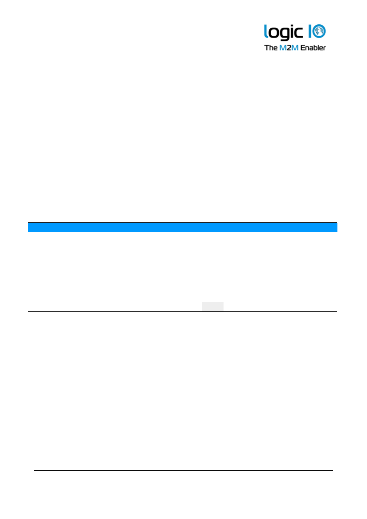
Power consumption
The table below shows detailed information about the typical power consumption for the RTCU
NX-200 device while it is running.
Power consumption: Device operating in normal mode
12V
24V
BAT
Device active
85
35
225
mA
Device active with Cellular on LTE*
110
55
300
mA
Cell idle @ -65 dBm*
Device active with GPRS on LTE*
300
150
700
mA
Cell @ -65 dBm.
Active communication.
Battery not charging*
Device active with GNSS on
100
45
280
mA
Mode 4
Device active with WLAN on
100
55
305
mA
Connected to AP, in idle
Device active with Ethernet on
100
45
310
mA
Connected to switch, in idle
Device active while charging
600
300
-
mA
Note: Values marked with (*) is an average and should be considered as guidelines as they may
vary depending on the Cellular signal level.
Note: Power consumption was measured from a fully charged battery.
Page 36
RTCU NX-200 Technical Manual V1.00
Advanced Automotive M2MI/IoT Gateway
Logic IO ApS. Ph: (+45) 7625 0210
Holmboes Allé 14 Fax: (+45) 7625 0211
8700 Horsens Page 36 of 45 Email: [email protected]
Denmark www.logicio.com
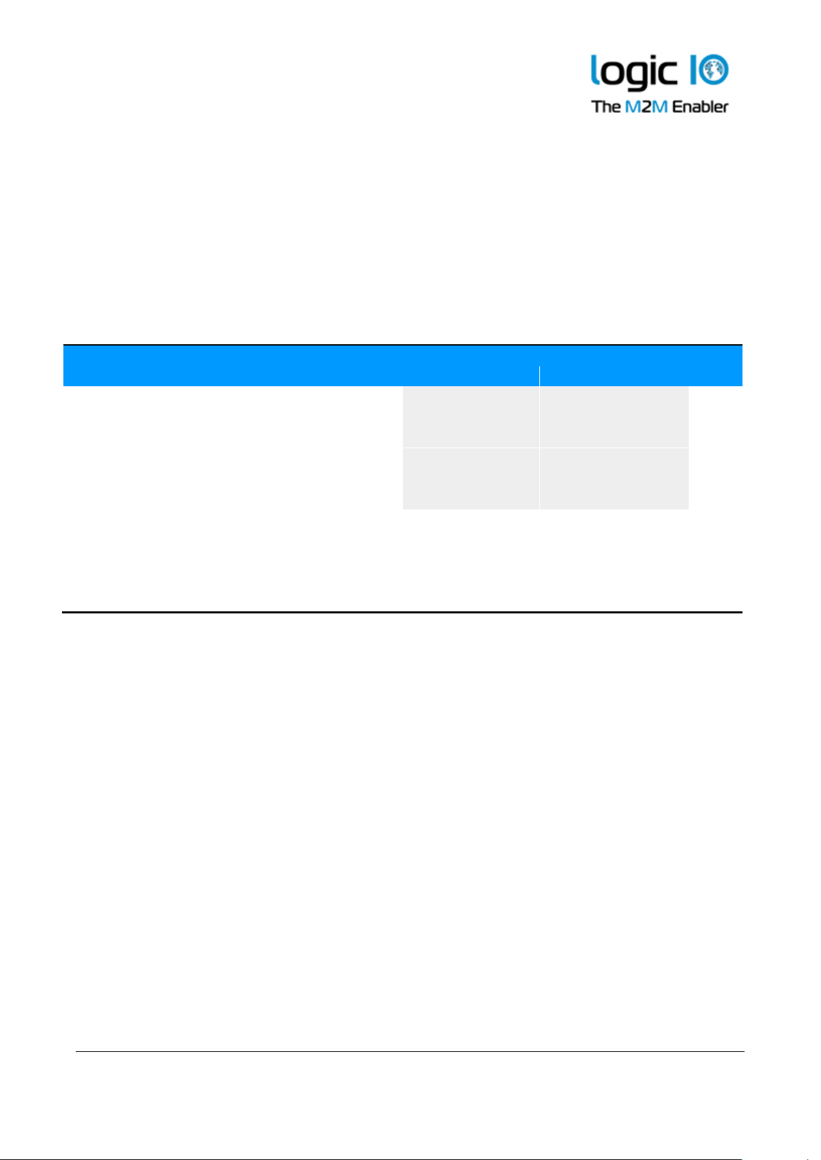
The table below shows detailed information about the typical power consumption for the RTCU
NX-200 device when it is in power-saving modes.
The following power-saving modes are used:
• Mode 1: LED blinks every ~10 s, resumes the application when it is awoken.
• Mode 2: Does not blink, resumes the application when it is awoken.
• Mode 3: Does not blink, resets the device when it is awoken.
See the RTCU IDE on-line manual for information about how to use the power saving modes.
Power consumption: Device operating in power-saving modes
Mode 1
Mode 2
Mode 3
Wake-up source:
12V
24V
BAT
12V
24V
BAT
12V
24V
BAT
Cellular
20
10
50 - - - - - -
mA
CAN 1
4.5
2.5
15 - - - - - -
mA
CAN 2
8.5
4.5
24 - - - - - -
mA
RS232 1 mode 0 / 1
4.5 / 4
2.4 / 2.2
14 / 13
- - - - - - mA
RS232 2 mode 0 / 1
5 / 4.5
2.7 / 2.5
15 / 14
- - - - - - mA
RS485
4.5
2.5
14 - - - - - -
mA
Time
1.1
0.7
2.9
0.7
0.4
1.6
0.4
0.3
0.7
mA
Din 1-5
1.1
0.7
2.9
0.7
0.4
1.6
0.4
0.3
0.75
mA
Power Failure
1.1
0.7
2.9
0.7
0.4
1.6
0.4
0.3
0.75
mA
Power Apply
1.1
0.7
2.9
0.7
0.4
1.6
0.4
0.3
0.75
mA
Vibration
1.2
0.7
3.2
0.7
0.4
1.9
0.5
0.5
1.1
mA
Note: If wake-up on both power fail and power apply are enabled, mode 2 and 3 are not
supported.
Note: Power consumption was measured from a fully charged battery.
Note: The RS232 ports have support for two different wake-up configurations. Mode 0 will wake
on valid data while mode 1 will wake on any change on the interface.
Note: The power consumption for CAN 1 has been measured with write disabled.
Page 37
RTCU NX-200 Technical Manual V1.00
Advanced Automotive M2MI/IoT Gateway
Logic IO ApS. Ph: (+45) 7625 0210
Holmboes Allé 14 Fax: (+45) 7625 0211
8700 Horsens Page 37 of 45 Email: [email protected]
Denmark www.logicio.com
Appendix A – Installing the external SIM-Card
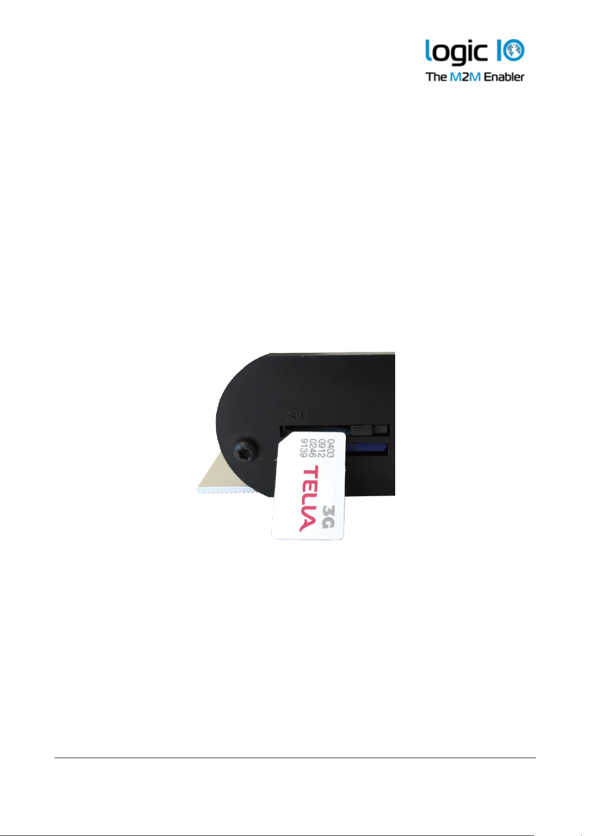
The external accessible SIM card reader has a push/push eject system and a mechanical lock for
secure installation of the SIM card.
Orientate the card as shown below and insert it into the card reader. Push the card into the reader
until a click sound occurs – the card will now stay in its position. It might be necessary to use a
small tool or pencil as the card, for protection purposes it is placed underneath the enclosure
surface. Furthermore, a mechanical slide lock can be used to prevent it from being removed
accidentally.
To remove the card, slide the lock to its unlocked position and push the card into the reader until a
small click sound occurs. The reader will now eject the card. It might be necessary to use a small
tool or pencil to push the card into the reader.
SIM card orientation
Page 38
RTCU NX-200 Technical Manual V1.00
Advanced Automotive M2MI/IoT Gateway
Logic IO ApS. Ph: (+45) 7625 0210
Holmboes Allé 14 Fax: (+45) 7625 0211
8700 Horsens Page 38 of 45 Email: [email protected]
Denmark www.logicio.com
Appendix B – Installing the internal SIM-Card
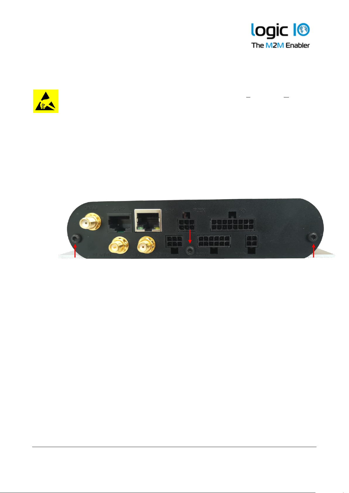
WARNING: Disassembling the device must be performed by a professional personal.
ATTENTION: The device internal electronics are sensitive to Electrostatic Discharge
(ESD) and must be handled only in an ESD safe environment.
Avoid touching the electronics components and parts.
The internal accessible SIM card reader is a hinged reader with a mechanical lock for secure
installation of the SIM card.
To gain access to the internal card reader, the circuit board must be pushed out. This operation is
described in the following steps:
1. Remove the three screws on the backplate.
2. Pull gently and slowly the backplate near the GNSS antenna connector. The circuit board is
fixed inside the encapsulation due to the internal battery holder and may require a small
amount of force. You may push from the front side, through the USB Host port 1 connector;
please do not push hard, nor use any tools that can damage the connector.
3. It's important to pull the circuit board evenly on both sides.
Page 39
RTCU NX-200 Technical Manual V1.00
Advanced Automotive M2MI/IoT Gateway
Logic IO ApS. Ph: (+45) 7625 0210
Holmboes Allé 14 Fax: (+45) 7625 0211
8700 Horsens Page 39 of 45 Email: [email protected]
Denmark www.logicio.com
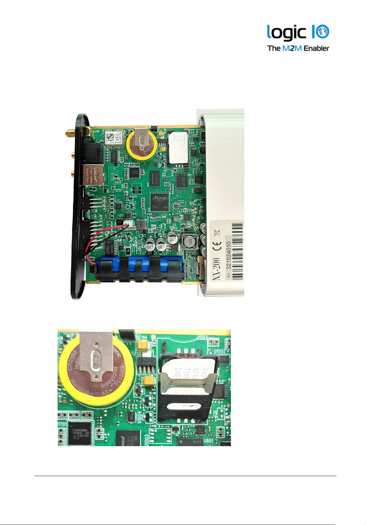
4. The circuit board will not have to be completely removed from the housing.
The SIM-card orientation on the reader is as follows:
5. Insert the SIM-card in the hinge
Page 40
RTCU NX-200 Technical Manual V1.00
Advanced Automotive M2MI/IoT Gateway
Logic IO ApS. Ph: (+45) 7625 0210
Holmboes Allé 14 Fax: (+45) 7625 0211
8700 Horsens Page 40 of 45 Email: [email protected]
Denmark www.logicio.com
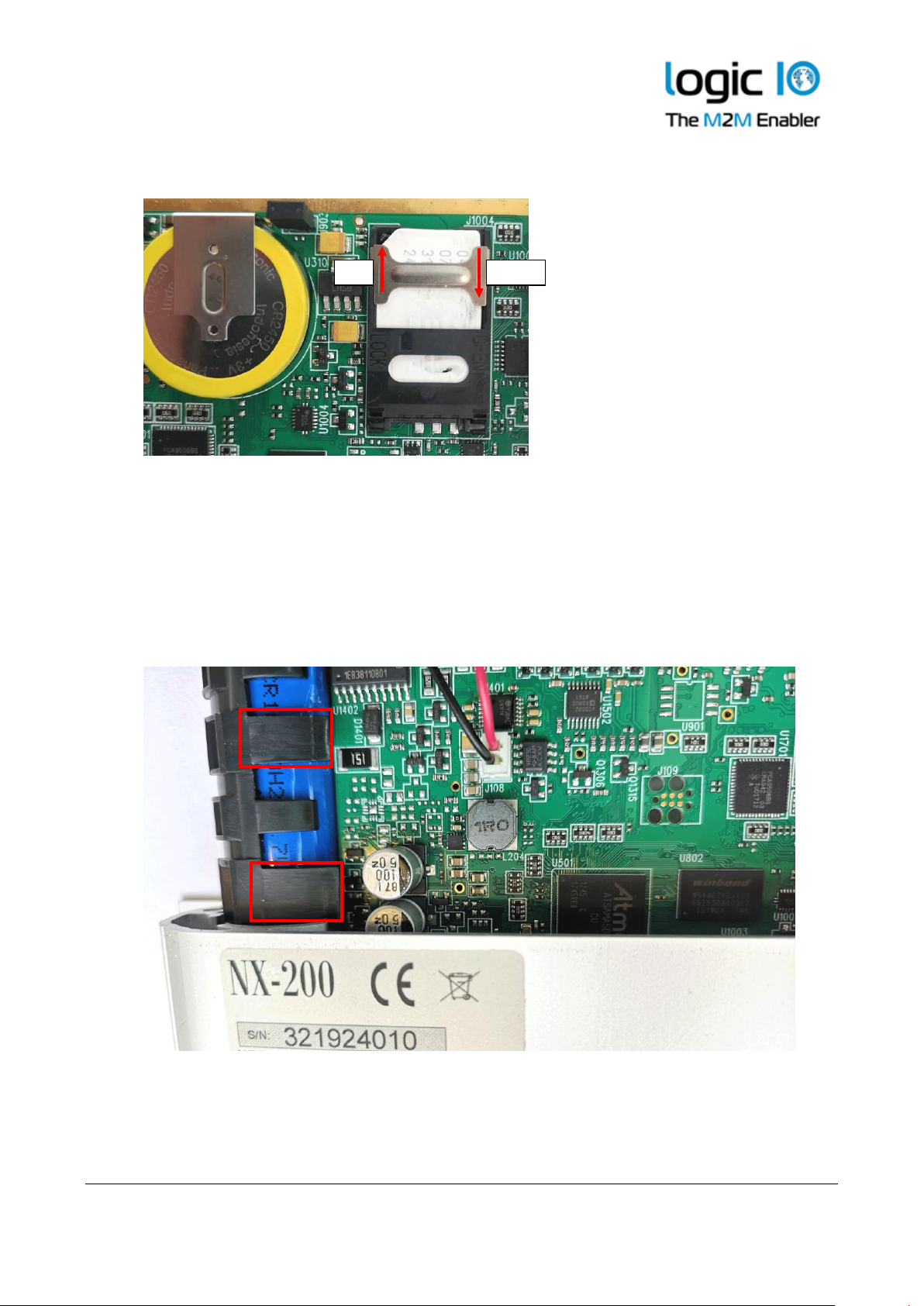
6. Close and lock the card reader
7. Push the circuit board into the encapsulation gently until the internal battery holder hits
the battery compartment of the encapsulation. The circuit board can't be pushed further
until the fixing flaps of the battery holder are squeezed inside the battery compartment of
the encapsulation.
8. Squeeze the first of the two flaps with two fingers on both top and bottom side of the
battery holder, push into the encapsulation, then squeeze the second flap.
9. When the baseboard is pushed into the encapsulation, align the backplate with the
connectors, and then secure the endplate with the three screws, that were removed in step
1.
Lock
Unlock
Page 41
RTCU NX-200 Technical Manual V1.00
Advanced Automotive M2MI/IoT Gateway
Logic IO ApS. Ph: (+45) 7625 0210
Holmboes Allé 14 Fax: (+45) 7625 0211
8700 Horsens Page 41 of 45 Email: [email protected]
Denmark www.logicio.com
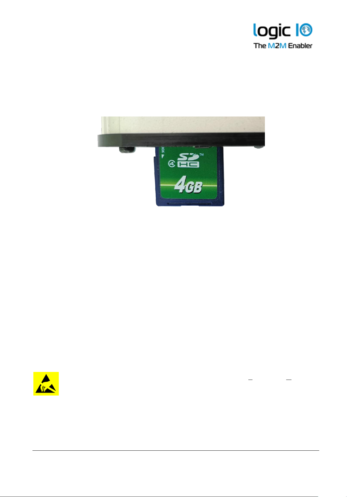
Appendix C – Installing the SD-CARD
To insert a card into the reader, orientate it as shown below and push the card into the reader until
a click sound occurs. Remove the card by pushing it into the reader until it clicks, and the reader
will eject the card. Avoid removing the SD-CARD during access to the card.
SD-CARD orientation
Appendix D - Enabling the CAN bus channel 1 write capability
Connecting the RTCU to a CAN network can be dangerous. If the RTCU is not configured with the
correct network parameters, it can lead to network corruption and may interfere with other
connected equipment on the bus. Especially in vehicles, great precautions must be observed to
prevent interruption of communication.
By default, reading from the CAN bus is enabled and writing to the CAN bus is disabled by a
hardware jumper inside the unit.
Installing this jumper, and thereby enabling the CAN-bus Write capability of the unit, is done on
the sole responsibility of the user. Logic IO can not be held responsible for any problems, or
damage due to the decision to enable the CAN-bus Write capability.
The following steps must be taken to enable the CAN bus Write capability of the unit:
ATTENTION: The device internal electronics are sensitive to Electrostatic Discharge
(ESD) and must be handled only in an ESD safe environment.
Avoid touching the electronics components and parts.
Page 42
RTCU NX-200 Technical Manual V1.00
Advanced Automotive M2MI/IoT Gateway
Logic IO ApS. Ph: (+45) 7625 0210
Holmboes Allé 14 Fax: (+45) 7625 0211
8700 Horsens Page 42 of 45 Email: [email protected]
Denmark www.logicio.com
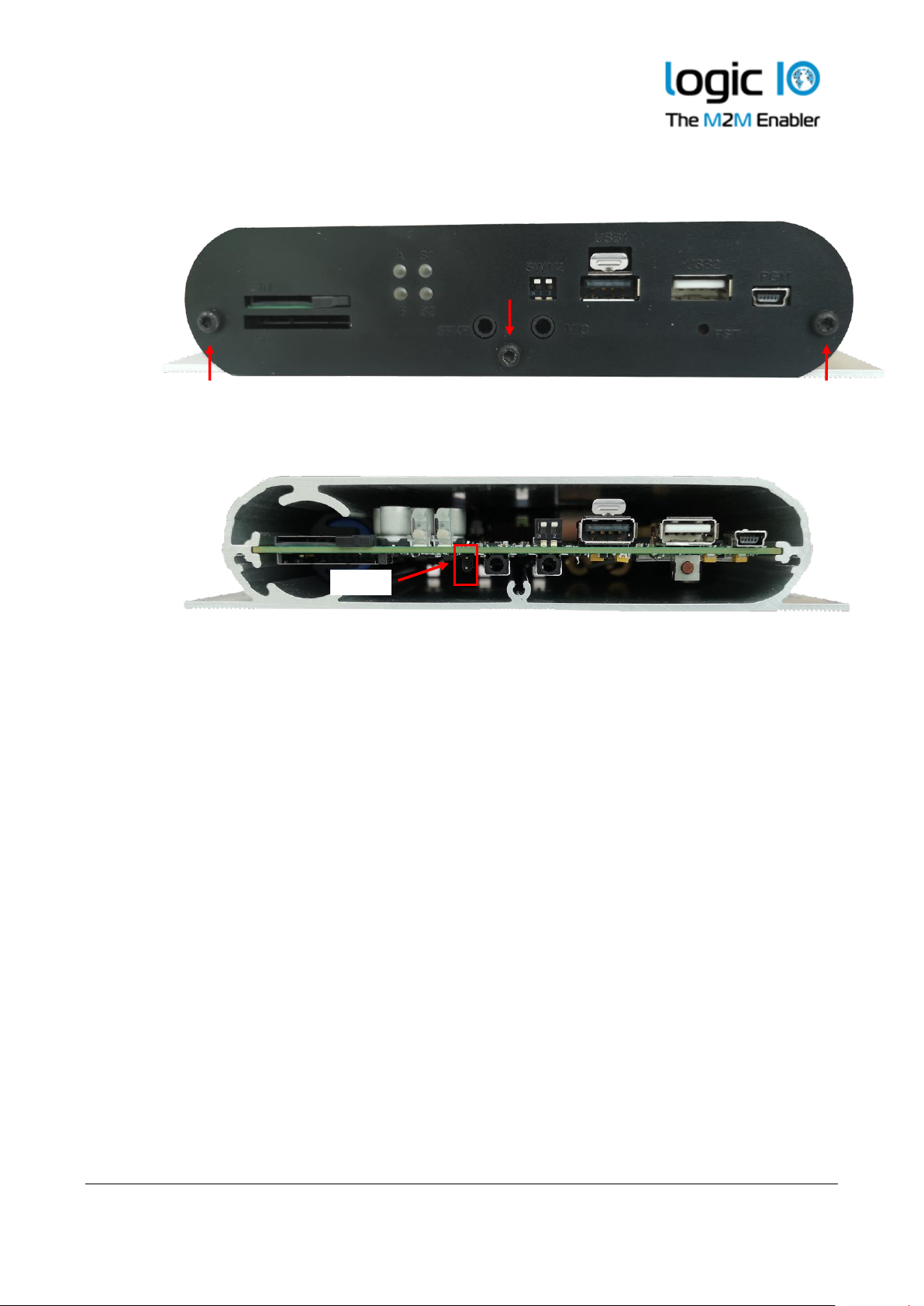
1. Remove the frontplate by removing the three screws.
2. The jumper is located on the bottom side of the circuit board, near the audio jack connector.
3. Insert the jumper. Please pick a suitable jumper, that is not too long to conflict with the
endplate.
4. Place the frontplate, so the connectors fit the openings, then tighten the two screws.
Be careful not to tighten the screws too much, thereby damaging the aluminum.
Appendix E - Open Source Disclaimer
The RTCU NX-200 products include several open-source software tools. This open-source software
is governed by the terms and conditions of the applicable open source license, and you are bound
by the terms and conditions of the applicable open source license in connection with your use and
distribution of the open-source software in this product.
Please refer to the separate document "RTCU Open Source Licenses.pdf" for detailed information
about the packages used in the RTCU NX-200 product.
Jumper
Page 43

RTCU NX-200 Technical Manual V1.00
Advanced Automotive M2MI/IoT Gateway
Logic IO ApS. Ph: (+45) 7625 0210
Holmboes Allé 14 Fax: (+45) 7625 0211
8700 Horsens Page 43 of 45 Email: [email protected]
Denmark www.logicio.com
RTCU NX-200 Specifications
Storage
• Persistent data flash.
• Non-volatile SRAM.
• Internal flash drive (Up-to 512 MByte).
• Circular datalogger.
• SD-CARD.
• USB flash media.
Wired Communication
• 100BASE-T Ethernet interface.
• 2 x Full CAN2.0B with hardware
filtering and multi-speed support.
• 2 x RS232. One with control signals.
• 1 x RS485.
• 1-Wire bus.
• 2 x USB host port. One with lock.
• USB service/programming port.
Cellular Engine
• LTE Cat.4 Engine(World Wide).
Max 150 Mbps(DL)/Max 50 Mbps(UL).
LTE FDD: 15 bands.
LTE-TDD: 4 bands.
WCDMA: 7 bands.
GSM: Quad-band.
• DTMF decoding / transmission.
• Digitized voice playback / IVR.
• Dual SIM card reader, with Mini-SIM
1.8/3 volt.
• Application controlled SIM card.
• Optional eSIM.
User Interaction
• 4 x bi-colour LED.
• DIP-switches.
• Virtual jumpers for RS485 and CAN
termination.
• CAN write enable jumper on one port.
• Reset / recovery switch.
RTCU M2M Platform
• NX32L Execution Architecture.
• Fully NX32 compatible.
• Larger capacity and higher
performance compared to NX32.
• Open and user-extendable API.
• RTCU M2M Platform SDK.
Wireless LAN
• WiFi at 2,4 GHz ISM bands.
• IEEE 801.11b/g/n/d/e/h/i.
• WPA/WPA2 certification.
• Up-to 150 Mbps.
Bluetooth
• Classic and Low Energy (LE).
• Bluetooth 2.1 + EDR up-to 3 Mbps
• Bluetooth 3.0 and 4.0 Dual mode.
• Intelligent co-existence with WLAN.
Audio
• Fully digitized audio system.
• Transfer, store and play audio.
• Amplified speaker output.
• Microphone input.
• Digitized GSM audio.
GNSS
• Multi-GNSS chip.
• GPS, GLONASS and GALILEO.
• 99 acquisition / 33 tracking
channels.
• SBAS (WAAS,EGNOS,MSAS,GAGAN).
• A-GPS capable.
• Anti-jamming, Noise cancellation.
• Active 3 volt GNSS antenna.
• Optional: Dead Reckoning.
NX32L Hardware Core
• Cortex-A5 32-bit ARM processor.
• Hardware floating point and DSP.
• 128 MByte LP-DDR RAM.
• 512 MByte NAND flash.
• 16 MByte NOR flash.
• 8 MByte Dataflash.
• 128 KByte SRAM with battery-backup.
• Real-time clock with battery-backup.
Security
• Embedded firewall.
• TLS/SSL support with full certifcate
management.
• TLS/SSL support for SMTP, MQTT, FTP,
HTTP, Gateway 2, and TCP/IP sockets.
• Hardware assisted strong encryption/
authentication: AES-128, AES-192, AES
256, DES, TripleDES, HASH, RND, and
RSA signature.
Page 44

RTCU NX-200 Technical Manual V1.00
Advanced Automotive M2MI/IoT Gateway
Logic IO ApS. Ph: (+45) 7625 0210
Holmboes Allé 14 Fax: (+45) 7625 0211
8700 Horsens Page 44 of 45 Email: [email protected]
Denmark www.logicio.com
Power Management
• Low-power modes.
• Wait for Event: Timer, Digital input,
accelerometer, RS232, RS485, CAN,
Cellular, Power change state.
• Wait for event, from: 0.4 mA@12V.
• Supervision of supply voltage / type.
Environmental Specification
• Operating temperature: -40 to 65°C.
• Battery charge temperature:
-10 to 45 °C.
• Recommended storage temperature:
0 to 45°C.
• Humidity: 5..90% (non condensing).
• Ingress Protection: IP20 .
Physical Characteristics
• Encapsulation: Aluminium profile.
• Colour: Anodized natural grey.
• Material: Aluminum and plastic.
• Approx. 500 gram without accessories.
• W 148 x H 34 x D 122 mm.
(without connectors / mounting flange).
Warranty
• Two-years return to factory parts and
labor.
• Optional warranty up to 5 years.
(restrictions apply).
Approvals
• 2007/46/EC UN ECE R10 Rev. 05 (E1).
• 2014/53/EU Radio Equipment Directive.
• 2011/65/EU RoHS Directive.
• Cellular:
GCF/CE/FCC/PTCRB/IC/Anatel/SRRC/NAL/
CCC/KC/NCC/JATE/TELEC/RCM/IFETEL/
FAC/NBTC/ICASA.
Battery and Charger
• On-board 2.6Ah (nominal) Li-Ion
battery.
• Intelligent charger with temperature
throttle and sub-zero degrees support.
Expandable
• I/O expansion Modbus modules.
• RFID-Reader*.
• Additional Ethernet port.
• Additional RS232 / RS485 ports.
• Industrial USB hub.
• Camera with HD video streaming.
• Speaker and microphone.
Electrical
• Operating voltage: 8 to 36 VDC.
• Short and reverse power protected.
• 5 VDC-out @ 300 mA.
• Dual USB 5 VDC @ 500 mA.
I/O Interface
• 4 x digital solid-state digital output.
Max. 36 volt / 1.5 A per. channel.
Short-circuit, ESD, Inductive kick-back
protected up to 20 mH.
• 5 x digital inputs with ignition.
Logic high: 8 to 40 VDC.
Logic low: -5 to 3 VDC.
Impedance: 14 kohm @ 12V.
• 4 x flex-inputs. Dual mode operation:
Analog mode: 0..30VDC
Digital mode: 0..30VDC.
Impedance: 120 kohm @ 12V.
Multi configuration support.
• 2 x analog inputs.
Range is 0..10VDC.
Resolution: 12 bit
Accuracy: Typ. ±0.3% FSR @ 25°C.
Impedance: 40 kohm (V).
• Protected against transients and low-
pass filtered.
Sensors
• Temperature sensor.
• 3-axis Accelerometer. ±16g@16b.
• 3-axis Gyroscope. ±2000dps @16b.
• 3-axis Magnetometer. ±50 gauss @16b.
External Interfaces
• Plug-compatible with the MX2 turbo.
• SIM-card slots for mini-SIM card.
• SD-CARD slot.
• 2 x mini-jack for audio in/out.
• 4 x LED indicators and 2 x DIP switches.
• Reset/recovery switch.
• RJ45 for RS232 with full control signals.
• SMA Female connector for cellular.
• SMA-RP connector for WLAN and BT.
• SMA Female connector for GNSS.
• USB 2.0 Host port connectors.
• USB 2.0 Slave mini-USB connector.
• TE-Connectivity ”Mate’n’Lok’:
RS232, RS485, CAN I/O, Power,
Communicaton.
Technical data are subject to changes.
Page 45

RTCU NX-200 Technical Manual V1.00
Advanced Automotive M2MI/IoT Gateway
Logic IO ApS. Ph: (+45) 7625 0210
Holmboes Allé 14 Fax: (+45) 7625 0211
8700 Horsens Page 45 of 45 Email: [email protected]
Denmark www.logicio.com
* * * * END OF DOCUMENT * * * *
 Loading...