

Loewe Xemix 5106-DO Service manual
General Description
Adjustment Procedures
Block / Schematic Diagrams
Exploded Views / Parts List
TITLE
CHAPTER
TRACK
A -B REPEAT
SHUFFLE
FTS
CHAPTER
SCAN
VCD
Digital Versatile Disc
CLASS 1
LASER PRODUCT
LOEWE.
DVD-Player
Xemix 5106 DO
TIMETRACKTOTAL
TRACKTITLE
Art.-Nr. 61551
GB 230-90373.906
Anschlüsse:
Euro-AV
FBAS-Video Cinch (vernickelt)
S-Video
Audio-Stereo (vernickelt)
Subwoofer-Ausgang (vernickelt)
Digitalausgang koaxial (vernickelt)
Digitalausgang optisch
Front-Kopfhörer (6,3 mm) regelbar
Sonstiges:
Netzspannung/Frequenz 230 V,50/60 Hz
Leistungsaufnahme 20 W
Leistungsaufnahme im Stand-by-Betrieb
max. 5 Watt
Empf.Umgebungstemperatur +5º bis +40º
Abmessungen:
43,5 x 9 x 31 cm (B x H x T)
Masse:
4,1 kg
Zubehör:
Scart-Kabel 1,5 m
Video-/Audio-Cinch-Kabel 1,5 m
Frontblenden (Farben:Graphit,Platin)
1
DTS ist ein eingetragenes Warenzeichen der Digital
Theatre Systems,Inc.
2
Dolby Digital ist ein eingetragenes Warenzeichen der
Dolby Laboratories Licensing Corporation
3
Abhängig von DVD Software
Ausstattung:
Dual Laser
Digital Link
Virtuell 3-D-Sound
Sonderfunktionen:
Blickwinkel (Kameraposition):max. 9
3
Synchronsprache/Untertitel:
max. 8/max. 32
3
Favorite Track Selection
Persönliche Farbeinstellung
Resume
Kindersicherung: Player/Disk
On Screen Display (OSD) D-GB-I-F-ENL-S-P-FIN-DK-N
Wiedergabefunktionen:
Kapitel-,Titelsprung
Repeat: Kapitel, Titel, DVD/CD
Perfektes Standbild
Einzelbildfortschaltung
Variable Zeitlupe
Variabler Zeitraffer
Technische Daten
Allgemeines:
Disc-Formate
DVD,Audio-CD,CD-R,CD-RW,
VCD,SVCD,DVD + RW
Bild:
Norm: PAL/NTSC
Horizontale Auflösung (DVD):
>500 TV-Zeilen
Bildformat: 16 : 9, Letterbox 4 : 3,
Pan & Scan 4 :3
Digitale Bildverarbeitung:10 bit
Ton:
DTS
1
Dolby Digital
2
MPEG-1/-2
PCM
MP3-Wiedergabe
Digitale Audiosignalverarbeitung:24 bit
Signal-/Rauschabstand: min. 90 dB
Dynamikumfang: min. 90 dB
Kanaltrennung (1kHz): min. 105 dB
Artikelnummer EAN Farbausführungen
61551 L00 4011880030298 Graphit
61551 A00 4011880030304 Platin
MP3-Wiedergabe möglich.
Mit nachrüstbaren Frontblenden perfekt
auf das Design der Loewe Fernsehgeräte
abgestimmt.
2 Digitalausgänge (koaxial,optisch).
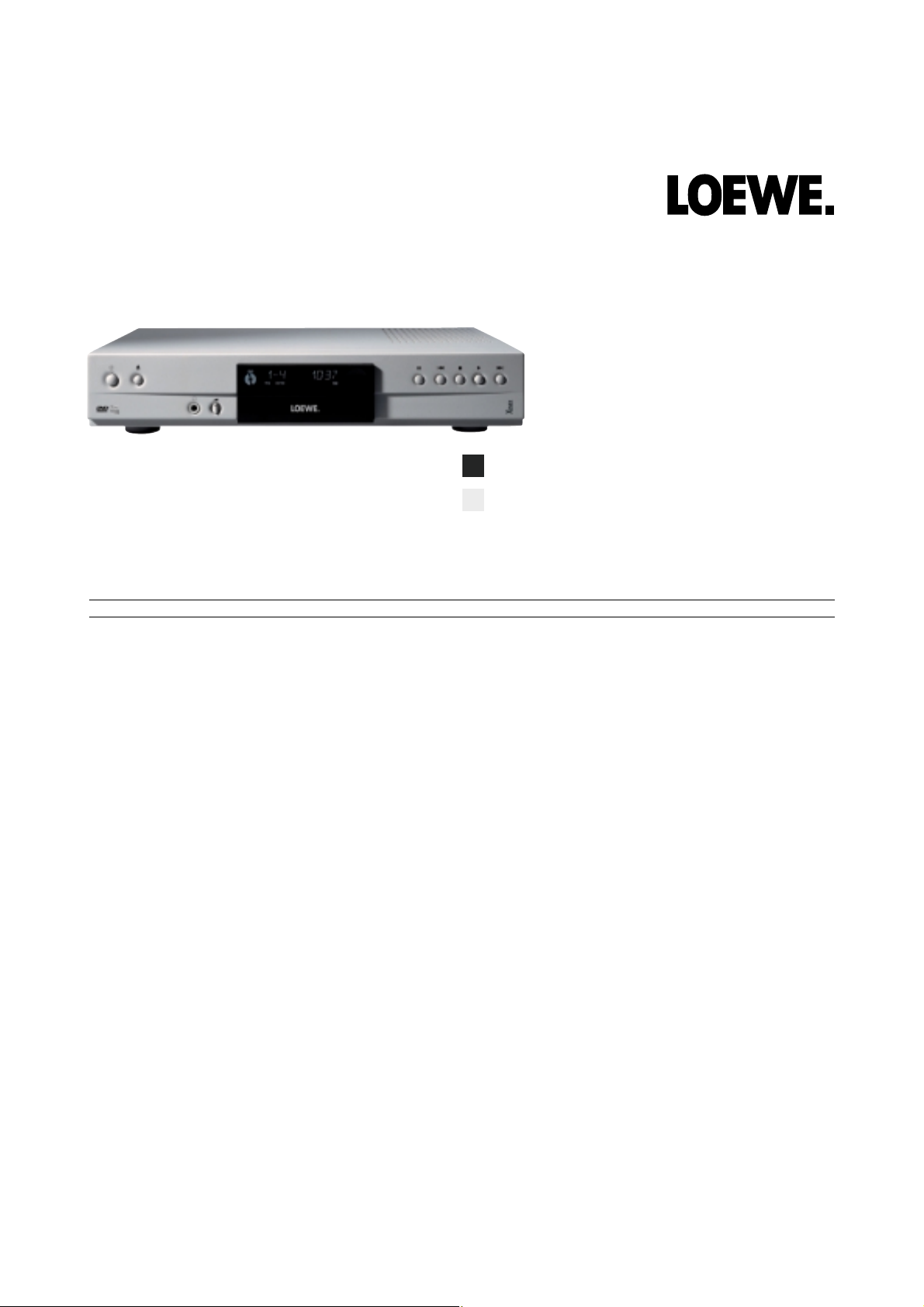
Platin
Graphit
Technische Spezifikationen
Xemix 5106 DO
MP3 - Wiedergabe
Folgende MP3-CD Formate werden nach ISO 9660 unterstützt:
· Maximal 30 Zeichen für Dateiname
· Maximal 8 Subordner möglich
· Variable Bit-Rate (VBR)
· Mögliche Sampling-Frequenzen für mp3:
ü 32 kHz
ü 44,1 kHz
ü 48 kHz
Tonqualität Bit-Raten Komressions-
verhältnis
AM 32 kbps 40 : 1 40 Std schlechte Tonqualität, die
FM 64 kbps 20 : 1 20 Std nicht zu empfehlen ist
fast CD Qualiät 96 kbps 15 : 1 15 Std gute Tonqualität mit diesen
CD 128 kbps 10 : 1 10 Std Bitraten
CD * 192 kbps 5 : 1 5 Std sehr hohe Kompression
CD * 256 kbps 2 : 1 2 Std findet kaum Verwendung
*àHierbei treten keine wesentlichen Verbesserungen auf.
Folgende MP3-CD Formate werden nicht unterstützt:
· *.WMA, *.AAC, *.DLF, *.M3U, *.PLS
· Chinesische Dateinamen
· Keine abgeschlossenen CD´s
· CD´s unter UDF-Format
Laufzeit
Ø Der digitale Ausgang ist während einer MP3 Wiedergabe gemutet.
Ø Bei Digital Audio MP3 ´s (DAM) kann nur ein digitales Signal wiedergegeben
werden.
Ø Die normale Einlesezeit von bis zu 10 Sekunden kann überschritten werden,
wenn eine CD mit großer Liederanzahl eingelegt wird.
Ø Bei einer in Multisession produzierten MP3-Disc, kann nur die erste Session
wiedergegeben werden.
Ø Bei der Wiedergabe von MP3 Discs ist ein gelegentliches „hüpfen“ oder
„springen“ aufgrund der Datenkompression wahrzunehmen. Dies ist normal!
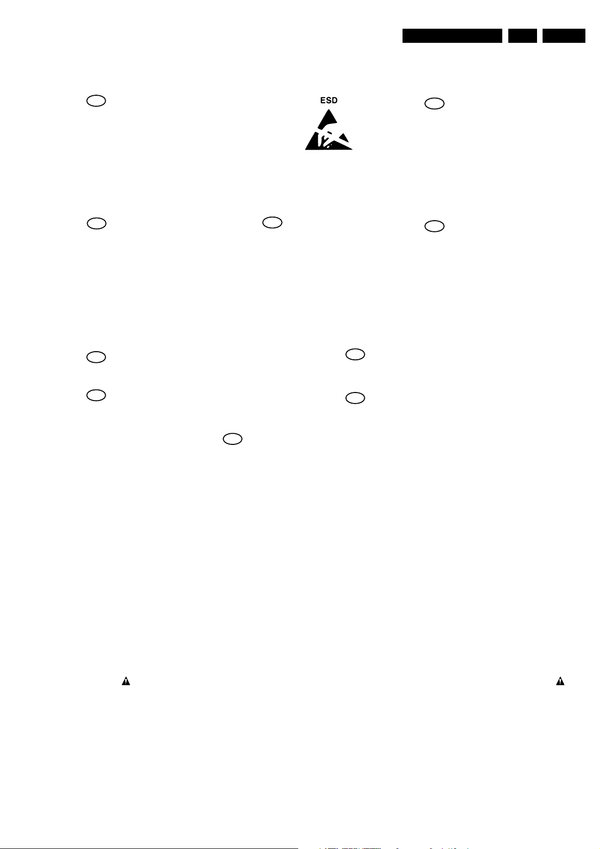
Warnings and Laser safety instructions
2. Warnings and Laser safety instructions
GB
WARNING
All ICs and many other semi-conductors are
susceptible to electrostatic discharges (ESD).
Careless handling during repair can reduce
life drastically.
When repairing, make sure that you are
connected with the same potential as the
mass of the set via a wrist wrap with
resistance.
Keep components and tools also at this
potential.
F
ATTENTION
D
WARNUNG
GB 3DVD 61551 2.
I
WAARSCHUWING
AVVERTIMENTO
NL
Alle IC’s en vele andere halfgeleiders zijn
gevoelig voor elektrostatische ontladingen
(ESD).
Onzorgvuldig behandelen tijdens reparatie
kan de levensduur drastisch doen
verminderen.
Zorg ervoor dat u tijdens reparatie via een
polsband met weerstand verbonden bent met
hetzelfde potentiaal als de massa van het
apparaat.
Houd componenten en hulpmiddelen ook op
ditzelfde potentiaal.
Tous les IC et beaucoup d’autres semiconducteurs sont sensibles aux décharges
statiques (ESD).
Leur longévité pourrait être considérablement
écourtée par le fait qu’aucune précaution
n’est prise a leur manipulation.
Lors de réparations, s’assurer de bien être
relié au même potentiel que la masse de
l’appareil et enfiler le bracelet serti d’une
résistance de sécurité.
Veiller a ce que les composants ainsi que les
outils que l’on utilise soient également a ce
potentiel.
Alle IC und viele andere Halbleiter sind
empfindlich gegen elektrostatische
Entladungen (ESD).
Unsorgfältige Behandlung bei der Reparatur
kann die Lebensdauer drastisch vermindern.
Sorgen sie dafür, das Sie im Reparaturfall
über ein Pulsarmband mit Widerstand mit
dem Massepotential des Gerätes verbunden
sind.
Halten Sie Bauteile und Hilfsmittel ebenfalls
auf diesem Potential.
GB
Safety regulations require that the set be restored to its original condition
and that parts which are identical with those specified be used.
NL
Veiligheidsbepalingen vereisen, dat het apparaat in zijn oorspronkelijke
toestand wordt terug gebracht en dat onderdelen, identiek aan de
gespecifieerde worden toegepast.
F
Les normes de sécurité exigent que l’appareil soit remis a l’état d’origine et
que soient utilisées les pièces de rechange identiques à celles spécifiées.
Tutti IC e parecchi semi-conduttori sono
sensibili alle scariche statiche (ESD).
La loro longevita potrebbe essere fortemente
ridatta in caso di non osservazione della piu
grande cauzione alla loro manipolazione.
Durante le riparazioni occorre quindi essere
collegato allo stesso potenziale che quello
della massa dell’apparecchio tramite un
braccialetto a resistenza.
Assicurarsi che i componenti e anche gli
utensili con quali si lavora siano anche a
questo potenziale.
D
Bei jeder Reparatur sind die geltenden Sicherheitsvorschriften zu beachten.
Der Originalzustand des Gerats darf nicht verandert werden.
Fur Reparaturen sind Original-Ersatzteile zu verwenden.
I
Le norme di sicurezza esigono che l’apparecchio venga rimesso nelle
condizioni originali e che siano utilizzati pezzi di ricambiago idetici a quelli
specificati.
SHOCK, FIRE HAZARD SERVICE TEST:
CAUTION: After servicing this appliance and prior to returning to customer, measure the resistance between
either primary AC cord connector pins (with unit NOT connected to AC mains and its Power switch ON), and the
face or Front Panel of product and controls and chassis bottom,
Any resistance measurement less than 1 Megohms should cause unit to be repaired or corrected before AC
power is applied, and verified before return to user/customer.
Ref.UL Standard NO.1492.
NOTE ON SAFETY:
Symbol
: Fire or electrical shock hazard. Only original parts should be used to replace any part with symbol
Any other component substitution(other than original type), may increase risk or fire or electrical shock hazard.
“Pour votre sécurité, ces documents
doivent être utilisés par des
spécialistes agrées, seuls habilités à
réparer votre appareil en panne.”
CL 96532065_002.eps
120799
GB 4 DVD 615512.
Warnings and Laser safety instructions
LASER SAFETY
This unit employs a laser. Only a qualified service person should remove the cover or attempt to service this
device, due to possible eye injury.
LASER DEVICE UNIT
Type: Semiconductor laser GaAlAs
Wave length: 650 nm (DVD)
780 nm (VCD/CD)
Output Power: 7 mW (DVD)
10 mW (VCD/CD)
Beam divergence: 60 degree
USE OF CONTROLS OR ADJUSTMENTS OR PERFORMANCE OF PROCEDURE OTHER THAN THOSE
SPECIFIED HEREIN MAY RESULT IN HAZARDOUS RADIATION EXPOSURE.
AVOID DIRECT EXPOSURE TO BEAM
WARNING
The use of optical instruments with this product will increase eye hazard.
Repair handling should take place as much as possible with a disc loaded inside the player
WARNING LOCATION: INSIDE ON LASER COVERSHIELD
CAUTION VISIBLE AND INVISIBLE LASER RADIATION WHEN OPEN AVOID EXPOSURE TO BEAM
ADVARSEL SYNLIG OG USYNLIG LASERSTRÅLING VED ÅBNING UNDGÅ UDSÆTTELSE FOR STRÅLING
ADVARSEL SYNLIG OG USYNLIG LASERSTRÅLING NÅR DEKSEL ÅPNES UNNGÅ EKSPONERING FOR STRÅLEN
VARNING SYNLIG OCH OSYNLIG LASERSTRÅLNING NÄR DENNA DEL ÄR ÖPPNAD BETRAKTA EJ STRÅLEN
VARO! AVATT AESSA OLET ALTTIINA NÄKYVÄLLE JA NÄKYMÄTTÖMÄLLE LASER SÄTEILYLLE. ÄLÄ KATSO SÄT EESEEN
VORSICHT SICHTBARE UND UNSICHTBARE LASERSTRAHLUNG WENN ABDECKUNG GEÖFFNET NICHT DEM STRAHL AUSSETSEN
DANGER VISIBLE AND INVISIBLE LASER RADIATI ON WHEN OPEN AVOID DIRECT EXPOSURE TO BEAM
AT TENTION RAYO NNEMENT LASER VISIBLE ET INVISIBLE EN CAS D'OUVERTURE EXPOSITION DANGEREUSE AU FAISCEAU
!
Warning for powersupply on position 1005
The primary side of the powersupply including the heatsink carries live mains voltage when the
player is connected to the mains even when the player is swiched off !
This primary area is not shielded so it is possible to touch copper tracks and/or components when
servicing the player. Service personnel have to take precautions to prevent touching this area or
components in this area .
The primary side of the powersupply has been indicated with a lightning stroke and a stripe-marked
printed on the printed wiring board
CL06532096_022.eps
060700

Warnings and Laser safety instructions
2.1 Notes
2.1.1 DVD-Module
For repair of the DVD-module SD3, the service manual 230-
90375.912 has to be used.
2.1.2 ComPair
Software-update abrufbar vom Loewe-FTP-Server
GB 5DVD 61551 2.
GB 14 DVD 615513.
Directions For Use
Personal Notes:
English
– Check if there is power at the AC outlet by plugging in another appliance.
– Check the video connection.
from the centre to the edge in a straight line.
malfunction.
– Sometimes a small amount of picture distortion may appear .This is not a
signal of your television.
– If your TV video signal is NTSC , select the NTSC setting at the DVD player.
– If your video signal is PAL, select the PAL setting - see NTSC/PAL SETTINGS.
21
ERVICE
S
EQUESTING
R
EFORE
B
PCM.
– If you are using a HiFi amplifier, try another sound source.
– Check the settings menu to make sure the digital output is set to ALL or
receiver capabilities.
– Check if the audio format of the selected audio language matches your
– Not applicable for MP3
– Clean the disc.
– Check if the disc is defective by trying another disc.
– Check to see if the disc is defective, badly scratched or warped (not flat)
outlet. (Please ensure that the set is not in Initial Setup mode)
– Inspect or replace the batteries in the remote control.
Before Requesting Service
If it appears that the DVD Video player is faulty, first consult this checklist. It may be that something has been overlooked. Under
no circumstances attempt to repair the system yourself; this will invalidate the warranty.
Look for the specific symptom(s). Then perform only the actions listed to remedy the specific symptom(s).
Symptom Remedy
No power – Make sure the power cord is properly connected.
No picture – Check if the TV is switched on.
Distorted picture – Check the disc for fingerprints and clean the disc with a soft cloth, wiping
Completely distorted picture – If the picture is distorted completely or if the picture rolls vertically,
or no colour with player menu. make sure the NTSC/PAL setting at the DVD player matches the video
Distorted or Black/White picture – The disc format does not match your TV’s video signal (PAL/NTSC) - see
No sound – Check audio connections.
with DVD or Video CD. NTSC/PAL Conversion.
Distorted sound from HiFi – Check to make sure that no audio connections are made to the amplifier
amplifier. phono input.
No audio at digital output. – Check the digital connections.
Disc can’t be played. – Ensure the disc label is facing up.
No return to start-up screen when – Reset the unit by switching the player off, then on again.
disc is removed. – Check to see if the programme requires another disc to be loaded.
The player does not respond to – Aim the remote control directly at the sensor on the front of the player.
the remote control. – Remove any obstacles between the player and the remote control.
Buttons do not work. – In order to completely reset the player, unplug the AC cord from the AC
Player does not respond to some – Operations may not be permitted by the disc. Refer to the instructions of
operating commands during the disc.
playback.
DVD Video player cannot read – Use a commonly available cleaning CD/DVD to clean the lens before
CDs/DVDs sending the DVD Video player for repair.
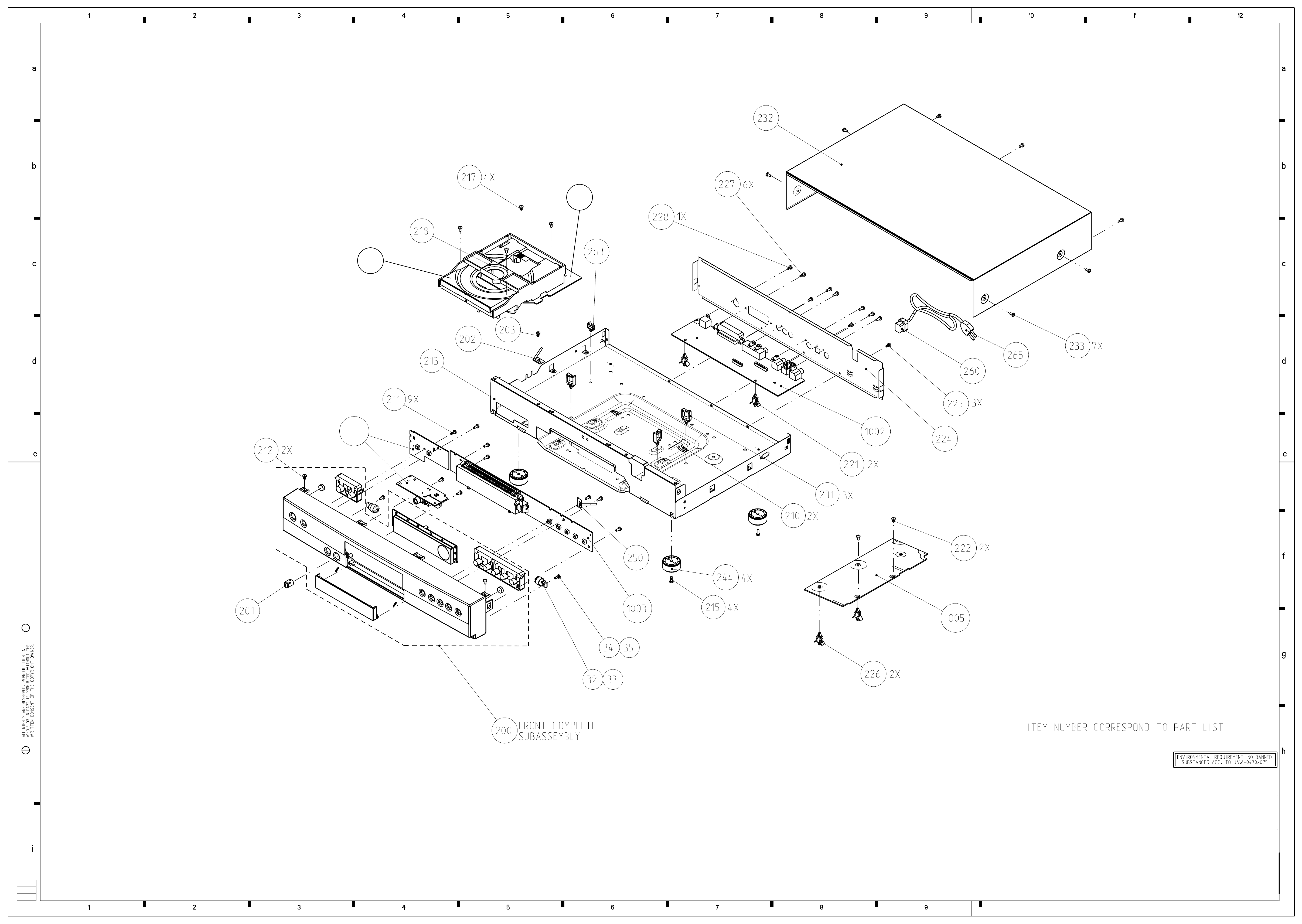
4. Mechanical instructions
4.1 Dismantling instrutions
(board to frame)
226 (board to frame)
-> Remove 2 screws 222
-> Release snaps of 2 spacer
-> Demount board
(skt cinch to back-plate)
and screw 228 ( S-video
to back-plate )
-> Remove screws 227
221
-> Release snaps of 2 spacers
-> Demount board
Mounting
Demounting
Power supply unit 1005
-> Remove connections
A/V board 1002
-> Remove connections
Mechanical instructions
GB 15DVD 61551 4.
240401
CL 16532007_057.eps
Cover 232
-> Remove 7 screws 233
remove
-> Lift cover at rearside to
Mono-board
DVD module 218
Front assy 200
( See instruction below )
-> Remove connections to
-> Open Tray
( front to frame )
-> Remove 2 screws 212
-> Unlock front from frame by
(module to frame)
-> Remove 4 screws 217
-> Demount module
releasing successively 6
snaps ( 2 each on the side,
top and bottom )
the set ( service position )
-> Place front assy in front of
DVD Mono board
-> See also exploded view of
DVD module
turntable motor and sledge
motor
-> Remove flex connections to
Standby board and switch
assy 1003B
-> Remove 2 screws 211
Headphone board 1006
-> Remove connections
-> Remove 3 knobs 208
(mono-board to VAL6011)
connection to OPU and wire
-> Remove carefully flex
(board to front) ,pay
-> Remove 3 screws 209
attention to earth spring
to the tray motor
252
-> Remove 4 screws 10 to 13
-> Demount board
by pulling it forward
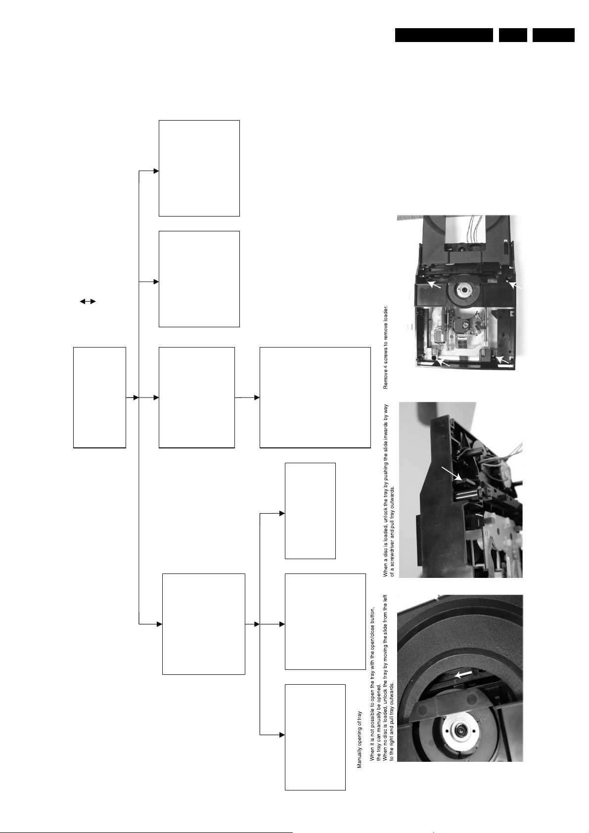
Remove 4 screws to remove loader.
-> Demount the board
When a disc is loaded, unlock the tray by pushing the slide inwards by way
of a screwdriver and pull tray outwards.
-> Demount board
DISMANTLING INSTRUCTIONS DVD7 SERIES
See exploded view for item numbers and diversity table for items used
Display board 1003A
-> Remove connections
-> Remove 7 screws 211
(board to front) ,pay attention
to earth spring 250
-> Demount board
Manually opening of tray
When it is not possible to open the tray with the open/close button,
the tray can manually be opened.
When no disc is loaded, unlock the tray by moving the slide from the left
to the right and pull tray outwards.
GB 16 DVD 615514.
Mechanical instructions
CL06532147_001.eps
151100
0001
1001
1004
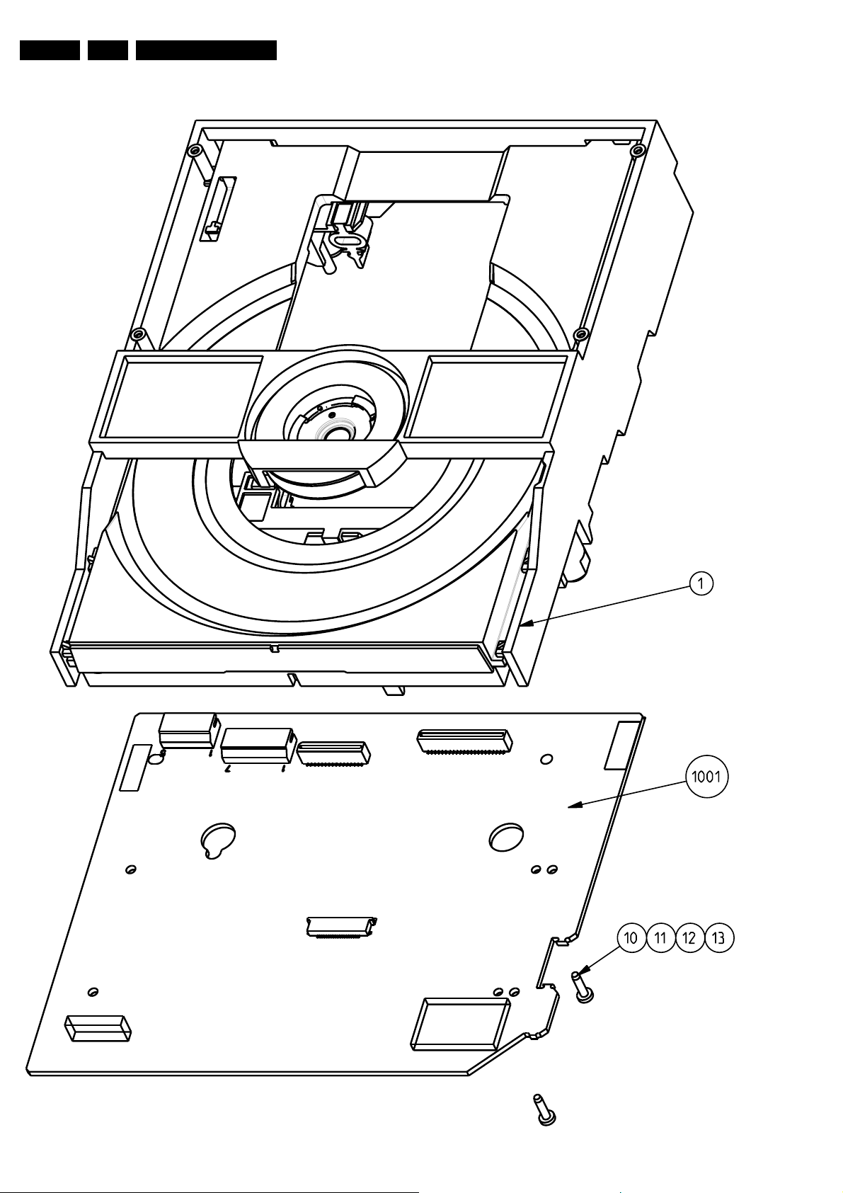
Note: Not all items in
exploded view are service parts!
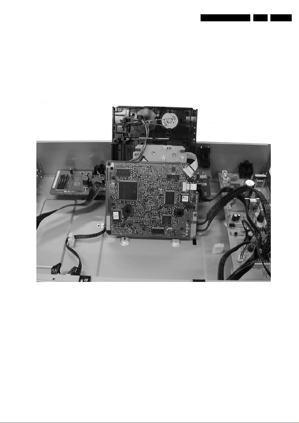
4.3 Service position
See figure 4-1 for the service position
1. Remove the cables from the cable tie housing.
2. Remove 4 screws that mount the DVD module to the
bottom frame.
3. Move the DVD module backward slightly and flip the
module over, so that the component side of the
board faces upwards, and the module is in the
service position.
Mechanical instructions
GB 19DVD 61551 4.
Figure 4-1
GB 20 DVD 615515.
Diagnostic Software Descriptions And Troubleshooting
5. Diagnostic Software Descriptions And Troubleshooting
5.1 Dealerscript
5.1.1 Purpose Of Dealer Script
The dealer script can give a diagnosis on a standalone DVD
player; no other equipment is needed to perform a number of
hardware tests to check if the DVD player is faulty. The
diagnosis issimply a "error" or "pass"message; no indication
is given of faulty hardware modules. Only tests within the
scope of the diagnostic software will be executed hence only
faults within this scope can be detected.
Nucleus Description
VideoColSetupComm
Checks the I2C interface with the RGB video processor on the Audio/Video
7
board (only for DVD players with RGB video processor).
PapChksFl
PapI2cDisp
PapS2bEcho
PapI2cNvram
PapNvramWrR
CompSdramWrR
Calculate and verify checksum of FLASH memory.
6
Checks the I2C interface with the slave processor on the display PCB.
5
Checks the I2C interface to the basic engine.
4
Checks the I2C interface with the NVRAM.
3
Pattern test of all locations in the NVRAM
2
Pattern test of all locations in the SDRAM(s).
1
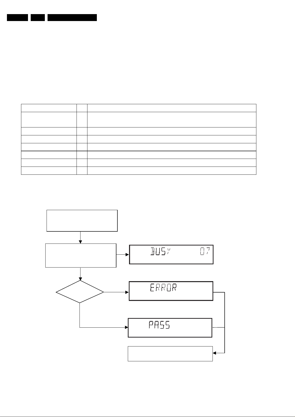
5.1.2 Contents Of Dealer Script
The dealer script executes all diagnostic nuclei that do not
need any user interaction and are meaningful on a
standalone DVD player.
The nuclei called in the dealer script are the following (the
number after each nucleus name corresponds with the
number being on the local display when the nucleus is
executed during the dealer script):
CL06532096_001.eps
050700
Press 2 keys simultaneously
<OPEN/CLOSE> + <PAUSE>
Connect to mains.
During the test, the following display
is shown: the counter counts down
from the number of nuclei to be run
before the test finishes. Example:
SET O.K.?
YES
NO
Figure 5-1
To exit DEALER SCRIPT ,disconnect from mains.
Figure 5-2
CL 96532065_004.eps
120799
Diagnostic Software Descriptions And Troubleshooting
s
GB 21DVD 61551 5.
5.2 Player Script
5.2.1 Purpose Of Player Script
The Player script will give the opportunity to perform a test
that will determine which of the DVD player's modules are
faulty, to read the error log and error bits and to perform an
endurance loop test. To successfully perform the tests, the
DVD player must be connected to a tv set to check the output
of a number of nuclei. For DVDv2b a multi-channel amplifier,
a set of 6 boxes and an external video source are necessary
to test. To be able to check results of certain nuclei, the
player script expects some interaction of the user (i.e. to
approve a test picture or a test sound). Some nuclei (e.g.
nuclei that test functionality of the Basic Engine module)
require that the DVD player itself is opened, to enable the
user to observe moving parts and approve their movement
visually. Only tests within the scope of the diagnostic
software will be executed hence only faults within this scope
can be detected.
5.2.2 Contents Of Player Script
The player script contains all nuclei that are useful on a DVD
player that is connected to a tv-set and help to determine
which module of the DVD player is faulty, as well as to read
out the contents of the error logs.
5.2.3 Structure Of Player Script
The player script consists of a set of nuclei testing the three
hardware modules in the DVD player: the Display PWB, the
Digital PWB and the Basic Engine.
Nuclei run by the player test need some user interaction; in
the next paragraph this interaction is described. The player
test is done in two phases:
1. Interactive tests: this part of the player test depends
strongly on user interaction and input to determine
nucleus results and to progress through the full test.
Reading the error log and error bits information can be
useful to determine any errors that occurred recently
during normal operation of the DVD player.
2. The loop test will loop through the list of nuclei
indefinitely, till theNEXT key is pressed. The list ofnuclei
is as follows:
• VideoColSetupComm
• VideoScartSwComm
• PapChksFlash
• PapI2cNvram
• CompSdramWrR
• PapS2bEcho
• PapI2cDisp
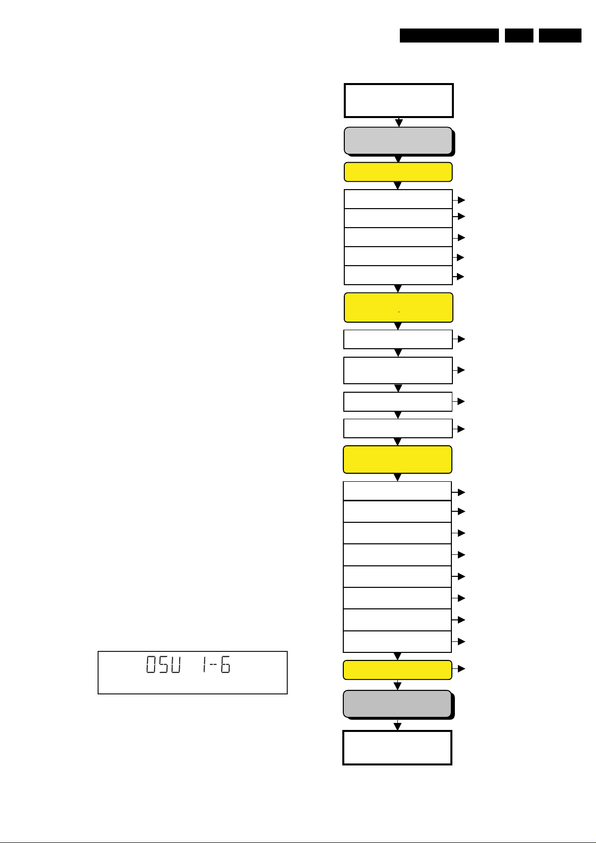
For DSW version 1.6 and above. the DSW version number
will be displayed on the local display. Press NEXT to
continue to the display test.
The display should look like the following:
5.2.4 Survey
Press 2 keys simultaneously
<OPEN/CLOSE> + <STOP>
Connect to main
INTERACTIVE TESTS
DISPLAY PCB
DISPLAY TEST
LED TEST
KEYBOARD TEST
REMOTE CONTROL
P50 LOOP BACK TEST
MONO PCB
DIGITAL PART
PICTURE TEST
SOUND 1 TEST
SCART DVD TEST
SCART LOOP TEST
SOUND 2 TEST
MONO PCB(SERVO)
& BASIC ENGINE
VERSION NUMBER
TRAY TEST
SLEDGE TEST
DISC MOTOR TEST
FOCUS TEST
RADIAL TEST
JUMP TEST
TRAY TEST
DispDisplay(30)
DispLed(29)
DispKeyb(27)
DispRc(28)
DispP50(60)
VideoColDencOn(23a)
AudioPinkNoiseOn(20a)
VideoScartSwDvd(54a)
VideoScartSwPass(54b)
AudioSineOn(21a)
BeVer(37)
BeTrayOut/In(43ab)
BeSledgeOut/In(41ab)
BeDiscMotorOn(39a)
BeFocusOn(38a)
BeRadialOn(40a)
BeGroovesIn/Mid/Out(42abc)
BeTrayOut/In(43ab)
ERROR LOG & BITS
CL 16532007_002.eps
010201
Figure 5-3
LOOP TEST
To exit player test,
disconnect from mains
Figure 5-4
LogReadErr(31)
LogReadbits(32)
= Dealer script exclusive of test2
CL 16532007_003.eps
300101
GB 22 DVD 615515.
5.3 Display PCB
5.3.1 Display Test
The display test is performed by nucleus DispDisplay. By
putting a series of test patterns on the local display, the local
display is tested. To step through all different patterns, the
user must either press PLAY (pattern is ok) or PAUSE
(pattern was incorrect) to proceed to the next pattern. The
display of patterns is continued in a cyclic manner until the
user presses NEXT. If the user presses NEXT before all
display patterns are tested, the DispDisplay nucleus will
return TRUE (display test successful).
5.3.2 LED Test
Diagnostic Software Descriptions And Troubleshooting
key id. key
0PLAY
1NEXT
2 PREVIOUS
3 PAUSE
4STOP
5 OPEN/CLOSE
6 3D-SURROUND
7 KEY- (Mic Control)
8 Once More (Mic Control)
9 KEY+(Mic Control)
A STAND BY
CL16532007_007.eps
300101
The LED(s) on the DVD player is (are) tested by nucleus
DispLed. The user must check if the LED(s) is (are) lighted;
ifitis,pressPLAY,ifitisnot,pressPAUSE.Bypressing
NEXT the script will proceed to the next test. If the user
presses NEXT before PLAY or PAUSE, the DispLed nucleus
will return TRUE (LED test successful).
If OK, press PLAY If NOK, press PAUSE
If OK, press PLAY If NOK, press PAUSE
If OK, press PLAY If NOK, press PAUSE
press NEXT to continue
CL 96532065_006.eps
120799
Figure 5-5
Figure 5-7
If any keys are detected more than once (due to hardware
error), the key-code is displayed twice (or more), with the
second digit increased by 1.
If the user does not press all keys minimally once (in any
order), theDispKeys nucleus will return FALSE and causean
error in the overall result of the player script.
The test will also pass if all buttons, except the microphone
key buttons, are pressed.
The user can leave the keyboard test by pressing the NEXT
key on the local display of the DVD player for at least one full
second.
The result of the keyboard test is shown on local display as
follows:
CL 96532065_009.eps
120799
Figure 5-8
Or
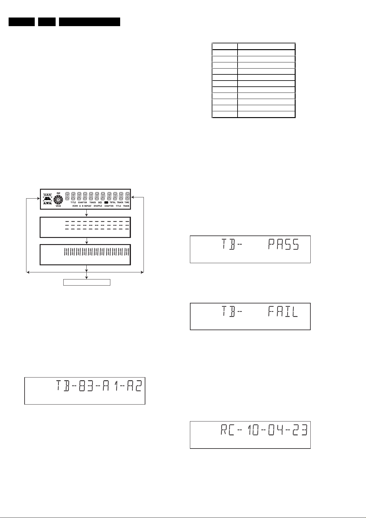
5.3.3 Keyboard Test
The keyboard of the DVD player is tested by nucleus
DispKeyb. The user is expected to press all keys on the local
keyboard once. The code of the key pressed is shown on the
local display (1 hexadecimal digit) immediately followed by a
(hexadecimal) number indicating how many times that key
has been pressed. Example of the local display during this
test:
Figure 5-6
The key-codes displayed on the local display will scroll from
right toleft whenthe displaygets full,the text "tb-" will remain
on display.
CL 96532065_007.eps
120799
Figure 5-9
Pressing NEXT on the local keyboard again will proceed to
the next text.
5.3.4 Remote Control Test
The remote control of the DVD player is tested by nucleus
DispRc. The user must press any key on the remote control
just once. The codes of the key pressed will be shown on the
local display in hexadecimal format. Example:
Figure 5-10
In this example 23 is the hexidecimal code ofthe pressed RC
key. The user can leave the remote-control test by pressing
NEXT on the local keyboard of the DVD player. The remote
CL 96532065_010.eps
120799
CL 96532065_011.eps
120799
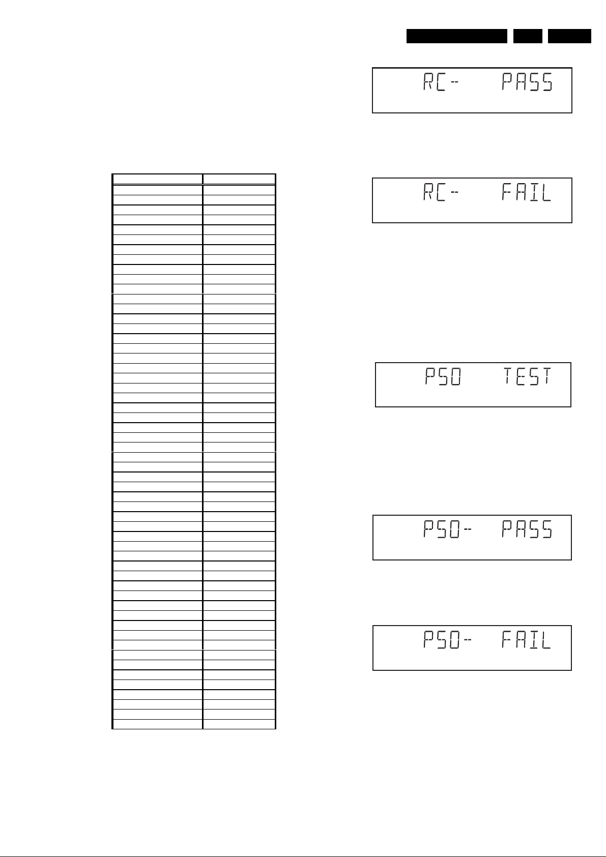
Diagnostic Software Descriptions And Troubleshooting
control test is successful if a code was received before the
user pressed the NEXT key; pressing the NEXT key before
pressing a key on the remote control gives an error in the
remote control test (note that the remote control test will also
fail if a key on the remote control was pressed but no code
was received). The remote control test does not check upon
the contents of the received code, that is it will not be
checked if the received code matches the key pressed. If
desired, the user can manually check this code by using a
code-table for the remote control key-codes.
C Key id Hexadecimal code
STANDBY 0C
STOP 31
PLAY
PLAY BACKWARD 2D
PAUSE 30
STEP FORWARD F6
STEP BACKWARD F5
FORWARD 28
FORWARD 4X DF
FORWARD 8X E0
BACKWARD 29
BACKWARD 4X DE
BACKWARD 8X DD
SLOW 22
SLOW 2 D9
SLOW BACKWARD 23
SLOW BACKWARD 2 DA
NEXT 20
PREVIOUS 21
CURSOR UP 58
CURSOR DOWN 59
CURSOR LEFT 5A
CURSOR RIGHT 5B
OK 5C
0 0
1 1
2 2
3 3
4 4
5 5
6 6
7 7
8 8
9 9
TOGGLE C8
ANGLE 85
AUDIO 4E
SUBTITLES 4B
SUBTITLE ON/OFF E3
ROOT MENU 54
TITLE MENU 71
MENU D1
SETUP MENU 82
OSD ON/OFF F
RETURN 83
RESUME D7
SCAN 2A
SHUFFLE 1C
REPEAT 1D
A/B REPEAT 3B
TOGGLE SCART 43
OPEN/CLOSE 42
FTS FB
KARAOKE E4
OPTION FA
Figure 5-11
After pressing NEXT, the result of the remote control test is
displayed on the local display of the DVD player as follows:
2C
CL06532096_003.eps
050700
Figure 5-12
Or
Figure 5-13
Pressing NEXT on the local keyboard again will proceed to
the next test.
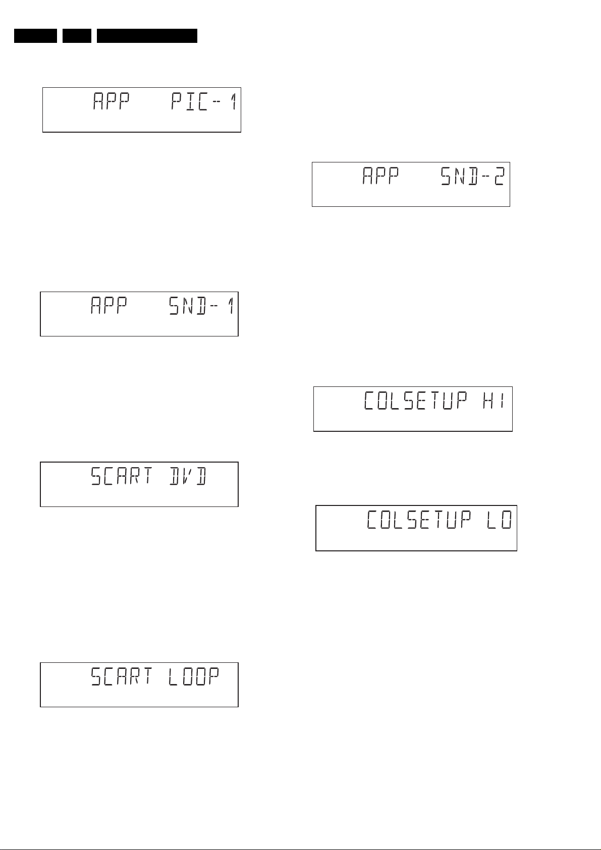
5.3.5 P50 Loop-Back Test
For the P50 loop-back test, the user must first press a key to
decide if the test is to be performed.
The display will show the following message:
Figure 5-14
If the user presses PAUSE, the P50 test will be skipped.
If the user presses PLAY, the P50 test is performed and the
result is displayed as follows:
Test successfull:
Figure 5-15
Test fails:
Figure 5-16
Press the NEXT key to continue to the next text
5.4 Mono PCB Digital Part
5.4.1 Picture Test
The picture test is performed by putting a predefined picture
(colour bar) on the display (nucleus VideoColDencOn) and
GB 23DVD 61551 5.
CL 96532065_013.eps
120799
CL 96532065_014.eps
120799
CL 16532007_004.eps
010201
CL 16532007_005.eps
010201
CL 16532007_006.eps
010201
GB 24 DVD 615515.
Diagnostic Software Descriptions And Troubleshooting
asking the user for confirmation. The display will show the
following message:
Figure 5-17
By pressing PLAY the user confirms the test, pressing
PAUSE will indicate the picture was invisible or incorrect.
Pressing NEXT will proceed to the next test
5.4.2 Sound 1 & SCART DVD Test
The first soundtest is performed by starting a pink noise
sound that needs confirmation from the user (nucleus
AudioPinkNoiseOn); the display will show the following
message very shortly:
Figure 5-18
This sound will only be audible from version cut3.1 of
Sti5505(item7503 on mono board) onwards. After starting up
sound 1, SCART loop-trough will be simultaneously active
during this test. SCART loop-trough will be measured with
the aid of an external video source.
When entering the SCART loop-trough, the local display
indicates:
CL 96532065_015.eps
120799
CL 96532065_016.eps
120799
The test can be left by pressing the NEXT key for more than
one second.
5.4.3 Sound 2 Test
The second soundtest is performed by producing a sine
sound (nucleus AudioSineOn). The signalcan be stopped by
pressing the STOP-key. The display will show the following
message:
Figure 5-21
By pressing PLAY the user confirms the test, pressing
PAUSE will indicate that something went wrong. Pressing
NEXT will proceed to the next; if the user presses NEXT
without pressing PLAY or PAUSE first, the result of this test
will be TRUE (sound ok).
5.4.4 Colour Setup Test
The colour setup test is performed by putting the internally
generated colour bar in different settings on the TV screen.
The first colour bar will be displayed in setting 1. the display
will show the following message:
Figure 5-22
CL 96532065_019.eps
120799
CL06532096_004.eps
050700
CL 96532065_017.eps
120799
Figure 5-19
On the TV screen a colour bar (generated by nucleus
VideoColDencOn) is visual and the internally generated
pinknoise is audible. By pressing PLAY the user confirms the
test, pressing PAUSE will indicate the sound was inaudible or
incorrect. Pressing NEXT will proceed to the next test; if the
user presses NEXT without pressing PLAY or PAUSE first,
the result of this test will be TRUE (sound ok). By pressing
the NEXT button there will be switched over to the external
source, this must become now visible on the TV screen
(using the SCART). The local display indicates:
CL 96532065_018.eps
120799
Figure 5-20
The internally generated colour bar is still available on the
CVBS and Y/C outputs. And the pinknoise-signal is still
available on the cinch audio outputs. By pressing the PREV
button, the internal generated colour bar becomes visual
again.
By pressing the NEXT button, you can go to the second
setting. The local display indicates:
Figure 5-23
By pressing the PREVIOUS button, the colour bar with the
first setting becomes visual again.
By pressing PLAY the user confirms the test, pressing
PAUSE will indicate that something went wrong.
The test can be left by pressing the NEXT key for more than
one second;if theuser pressesNEXT without pressing PLAY
or PAUSE first, the result of the test will be TRUE )colour setup ok).
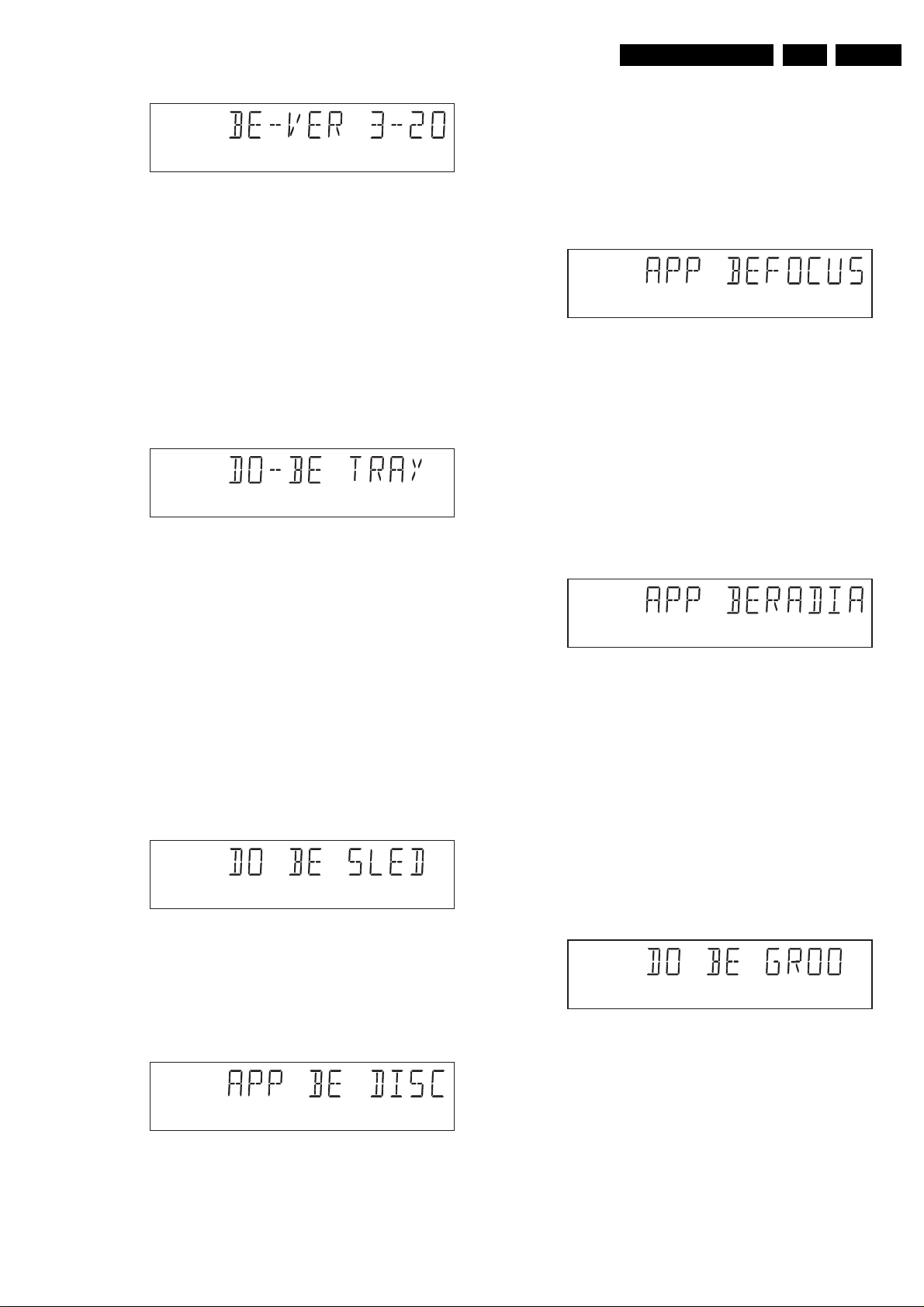
5.5 Basic Engine
5.5.1 Version Number
In the basic engine tests, the version number of the Basic
Engine will be shown first, as the following example:
CL06532096_005.eps
050700
Diagnostic Software Descriptions And Troubleshooting
Figure 5-24
By pressing the NEXT key, the Basic Engine tests are
started.
5.5.2 Tray Test
First, the tray is tested. The purpose of this test is also to give
the user the opportunity to put a disc in the tray of the DVD
player. Some tests on the Basic Engine require that a
disc(e.g. DVD MPTD test disc) is present in the player. At the
end of the Basic Engine tests this tray test will be repeated
solely to enable the user to remove the disc in the tray. The
local display will look as follows:
Figure 5-25
CL 96532065_020.eps
120799
CL 96532065_021.eps
120799
of the disc motor (nucleus BeDiscMotorOff). If the user
presses NEXT before pressing PLAY or PAUSE, the result of
this test will be TRUE (disc motor is running).
5.5.5 Focus Test (Visual Test)
The fourth Basic Engine test tests the focussing; first
focussing is turned on by calling nucleus BeFocusOn. The
display will look as follows:
Figure 5-28
By pressing PLAY the user confirms that the focussing was
succesful; pressing PAUSE indicates a focussing failure.
Pressing NEXT proceeds to the next test after a reset of the
focussing (nucleus BeFocusOff); if NEXT is pressed before
PLAY or PAUSE, the result of this test will be TRUE (focus
successful).
5.5.6 Radial Test (Visual & Listening Test)
The fifth Basic Engine test tests the radial functionality
(nucleus BeRadialOn); the local display looks as follows:
GB 25DVD 61551 5.
CL 96532065_024.eps
120799
By pressing PLAY or PAUSE the user can togglethe position
of the tray. Note that this test will not contribute to the test
result of the Basic Engine. Pressing NEXT will proceed to the
next test, after the tray has been closed (by the software) if it
was open.
5.5.3 Sledge Test (Visual Test)
The second Basic Engine test tests the sledge; the user can
move the sledge as many times as desired by using PLAY
(nucleus BeSledgeOut) and PAUSE (nucleus BeSledgeIn).
Pressing NEXT on the local keyboard proceeds to the next
test. Note that this test will not contribute to the test result of
the Basic Engine. The local display will look as follows during
the sledge test:
Figure 5-26
5.5.4 Disc Motor Test (Visual Test)
The third Basic Engine test tests the disc motor (nucleus
BeDiscMotorOn); the local display looks as follows:
CL 96532065_022.eps
120799
Figure 5-29
By pressing PLAY the user confirms that the radial function
worked; pressing PAUSE indicates the function does not
work. Pressing NEXT proceeds to the next test, after a reset
of theradial (nucleus BeRadialOff). If the user presses NEXT
before pressingPLAY or PAUSE, the resultof this test will be
TRUE (radial successful).
5.5.7 Jump Test (Listening Test)
The sixth and last Basic Engine test tests the jumping by
calling nuclei BeGroovesIn, BeGroovesMid and
BeGroovesOut. During this test, the local display looks as
follows:
Figure 5-30
CL 96532065_025.eps
120799
CL 96532065_026.eps
120799
CL 96532065_023.eps
120799
Figure 5-27
By pressing PLAY the user confirms that the disc motor is
running; pressing PAUSE indicates the disc motor does not
work. Pressing NEXT proceeds to the next test, after a reset
The user can switch between the three different types of
groove settings by pressing PLAY (forward to next nucleus in
the list In-Mid-Out) or PAUSE (backward in the list In-MidOut). This is done in a cyclic manner; note that this test will
not contribute to the test result of the Basic Engine. Pressing
NEXT proceeds to the next test, after the disc motor has
been shut off with a call to nucleus BeDiscMotorOff.
GB 26 DVD 615515.
5.5.8 Tray Test
As a last action for the Basic Engine tests, the tray test is
repeated. The local display will look as follows:
Diagnostic Software Descriptions And Troubleshooting
Figure 5-34
CL 96532065_030.eps
120799
Figure 5-31
This test is meant to give the user the opportunity to remove
the discin the tray. The tray position canbe toggled using the
PLAY and PAUSE key. The tray will be closed (by the
software, ifit isopen) beforeproceeding to the next test when
the user presses the NEXT key.
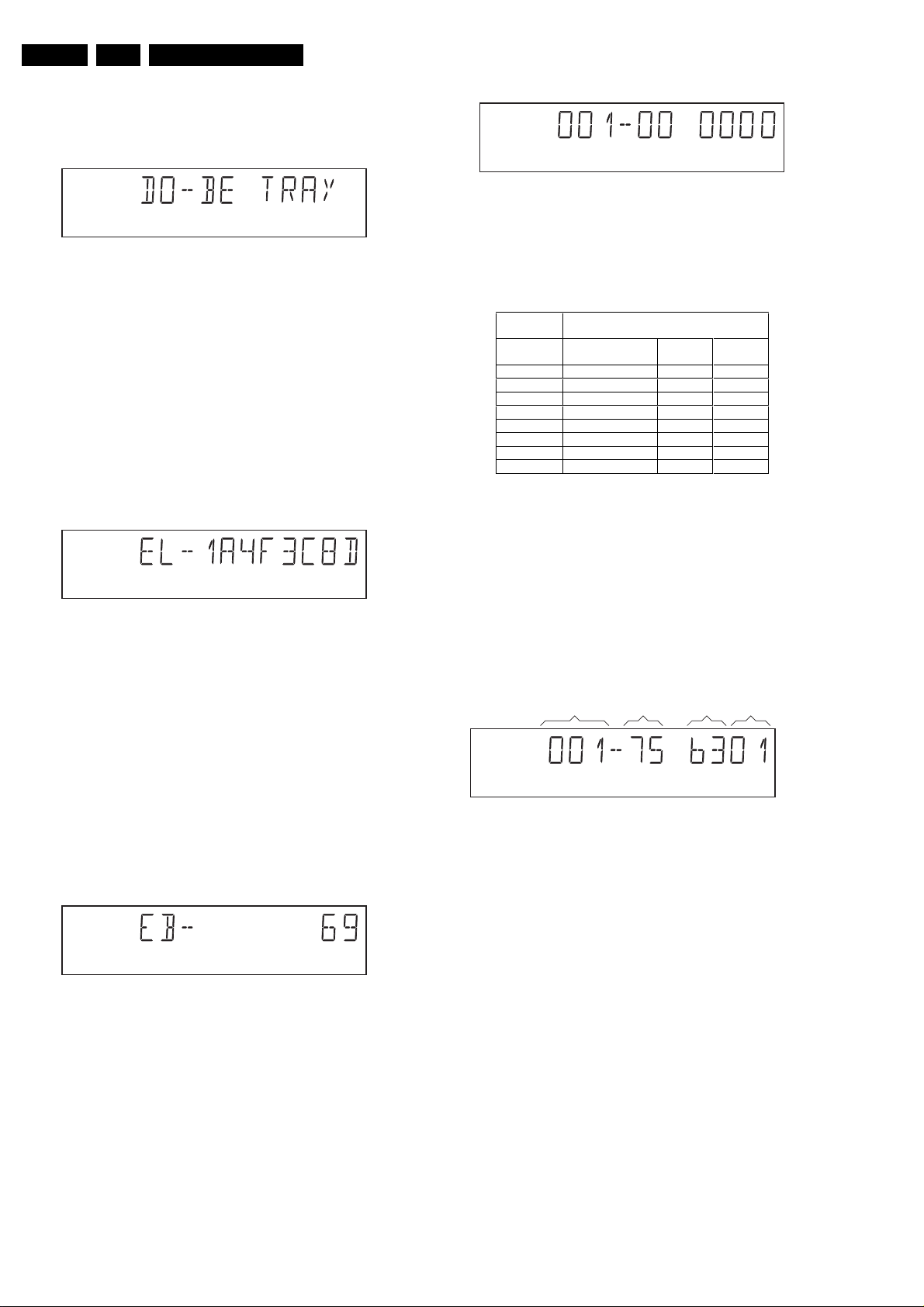
5.5.9 Error Log (See Table On Page 30)
Reading the error log anderror bits information canbe useful
to determine any errors that occurred recently during normal
operation ofthe DVD player. Reading the error log is doneby
nucleus LogReadErr. The display during the errorlogreadout
looks as follows :
Figure 5-32
By pressing PLAY or PAUSE the user can move forward or
backward (respectively) through the logged error codes. The
highlighted number indicates which errorcode is currently on
display (in the example above, errorcode number 4 is
displayed). If "0000" is displayed at all positions, the error log
is empty. Display of the logged errors is done in a cyclic
manner. The errorcode withthe lowest highlighted number is
the most recent. By pressing NEXT on the local keyboard,
the user can proceed to the next test.
5.5.10 Error Bits (See Table On Page 30)
Reading the error bits is done by nucleus LogReadBits. The
display during the errorbits readout looks as follows:
CL 96532065_027.eps
120799
CL 96532065_028.eps
120799
CL 96532065_029.eps
120799
The left side of the display contains a 3-digit code, which can
have a value between 000 and 111. These values are to be
interpreted as follows:
Displayed
Value
000 ok ok ok
001 ok ok faulty
010 ok faulty ok
011 ok faulty faulty
100 faulty ok ok
101 faulty ok faulty
110 faulty faulty ok
111 faulty faulty faulty
Indication for each module
Basic Engine Mono
PCB
Display
PCB
CL 96532065_031.eps
120799
Figure 5-35
The loop test will perform the same nuclei as the dealer test,
but it will loop through the list of nuclei indefinitely. The
display of the DVD player will display not onlythe three digits
indicating correct/faulty modules and the last found error
code (as mentioned, faults are detected as far as theycan be
within the scope of the diagnostic software), but also a loop
counter indicating how many times the loop has been gone
through. Example:
FAULTY
MODULE(S)
LOOP
COUNTER NUCLEUS ERROR
CL 96532065_032.eps
120799
Figure 5-36
The number after the hyphen indicates the number of times
the loop test has beenperformed; the 4 digits at the right side
of the display show the last error that was found when
running the loop test: the leftmost two digits of this code
indicate which nucleus resulted in a fault; the rightmost two
digits refer to the faultcode within that nucleus. For further
explanation of this error code, see list of error codes below.
Figure 5-33
Only the set errorbits will be shown by their (decimal)
number. Refer to the appropriate documentation for the
explanation of each bit number. If the display only shows
"EB-0", no error bits were set. By pressing NEXT the user
can continue to the next test.
5.6 Loop Test (See Table Below)
At the start of the loop test, the display will show the result of
the interactive player test:
 Loading...