

Page 1

Serviceanleitung.
Service Manual. Manuel de Service.
M 1000
M 1001
Xelos M55 VT 57493
Xelos M37 VT
Art.-Nr. 57483
Xelos M55 VT
Art.-Nr. 57493
Xelos M37 L
Art.-Nr. 57484
Xelos M55 L
Art.-Nr. 57494
Page 2

Allgemeiner Teil / General Section / Partie générale M 1000 / M 1001
D
Inhaltsverzeichnis
Seite
Allgemeiner Teil .................................1-2... 1-16
Modulübersicht............................................................................. 1-3
Technische Daten ........................................................................ 1-4
Sicherheitshinweise ..................................................................... 1-5
Schaltplansymbole....................................................................... 1-8
Hinweise zu den Oszillogrammen.............................................. 1-12
Hinweise zu den Bauteilen......................................................... 1-12
Normen- und Kanaltabelle ......................................................... 1-13
Service- und Sonderfunktionen.................................................. 1-15
Abgleich ................................................2-1... 2-2
Chassisplatte ............................................................................... 2-1
Platinenabbildungen
und Schaltpläne .................................3-1... 3-36
Chassisplatte ............................................................................... 3-1
Oszillogramme Chassis ............................................................... 3-7
Chassisplatte vergrößert (Meßpunkte) ........................................ 3-9
GB
Table of Contents
Page
General Section..................................1-2... 1-18
Module List................................................................................... 1-3
Technical Data ............................................................................. 1-4
Service Notes............................................................................... 1-6
Circuit Diagram Symbols ............................................................. 1-8
Hints to the Oscillograms ........................................................... 1-12
Hints to Components ................................................................. 1-12
Tables of Norms and Channels ................................................. 1-13
Service and Special Functions................................................... 1-17
Seite
Teilschaltplan Netzteil ................................................................ 3-13
Teilschaltplan Ablenkung ........................................................... 3-15
Teilschaltplan Prozessor............................................................ 3-17
Teilschaltplan Tuner/Buchsen.................................................... 3-19
Teilschaltplan Video................................................................... 3-21
Teilschaltplan Audio................................................................... 3-23
Bildrohrplatte.............................................................................. 3-25
Prozessorplatte .......................................................................... 3-27
SAT-Baustein............................................................................. 3-30
Ersatzteillisten......................................4-1... 4-5
Loewe Service ...................................... 4-6…4-7
Loewe-Vertragswerkstätten ......................................................... 4-6
Loewe-Service und Logistik ......................................................... 4-6
Loewe Service Europa................................................................. 4-7
Loewe Service Übersee............................................................... 4-7
Page
Circuit Diagram Mains Section................................................... 3-13
Circuit Diagram Deflection Section ............................................ 3-15
Circuit Diagram Processor Section ............................................ 3-17
Circuit Diagram Tuner/Socket Section....................................... 3-19
Circuit Diagram Video ................................................................ 3-21
Circuit Diagram Audio ................................................................ 3-23
CRT Panel ................................................................................. 3-25
Processor Board ........................................................................ 3-27
SAT Module ............................................................................... 3-30
Adjustment ........................................... 2-3…2-4
Chassis Board.............................................................................. 2-3
Layout of the PCBs
and Circuit Diagrams .........................3-1... 3-36
Chassis Board.............................................................................. 3-1
Oscillograms Chassis .................................................................. 3-7
Chassis Board Enlarged (Testpoints) .......................................... 3-9
F
Sommaire
Page
Partie générale ...................................1-2... 1-20
Composition des appareils........................................................... 1-4
Caractéristiques techniques....................................................... .1-5
Informations sur la sécurité.......................................................... 1-7
Symboles des schémas ............................................................... 1-8
Indications pour les Oscillogrammes ......................................... 1-12
Precautions a observer .............................................................. 1-12
Tableaux des normes et des canaux ......................................... 1-13
Fonctions de service et fonctions spéciales............................... 1-19
Alignement............................................2-5... 2-6
C.I. châssis .................................................................................. 2-5
Circuits imprimés
et schémas électriques......................3-1... 3-36
C.I. châssis .................................................................................. 3-1
Oscillogrammes C.I. châssis........................................................ 3-7
Châssis agrandissement (points de mesures)............................. 3-9
Spare Parts Lists..................................4-1... 4-5
Loewe Service ...................................... 4-6…4-7
Loewe-Establishments................................................................. 4-6
Loewe-Service and Logistics ....................................................... 4-6
Loewe Service Europe................................................................. 4-7
Loewe Service Overseas ............................................................. 4-7
Page
Schéma de la partie Alimentation .............................................. 3-13
Schéma de la partie Déviation ................................................... 3-15
Schéma de la partie Circuit Microprocesseur ............................ 3-17
Schéma de la partie Tuner/Embases......................................... 3-19
Schéma de la partie Vidéo......................................................... 3-21
Schéma de la partie Audio......................................................... 3-23
C.I. Tube .................................................................................... 3-25
C.I. du processeur...................................................................... 3-27
Module SAT ............................................................................... 3-30
Liste de pièces détachées...................4-1... 4-5
Loewe Service ...................................... 4-6…4-7
Succursale Loewe........................................................................ 4-6
Loewe-Service et Logistics .......................................................... 4-6
Loewe Service Europe................................................................. 4-7
Loewe Service Overseas ............................................................. 4-7
1 - 2 LOEWE.-Service
Page 3

M 1000 / M 1001 Allgemeiner Teil / General Section / Partie générale
Modulübersicht / Module List / Composition des appareils
Sachnummer
Part Number
Référence N°
Chassis
Tuner PLL 81406 016 1200
29504 301 0100
Bildrohrplatte
CRT Panel
C.I. tube
Prozessorplatte
Processor Board
C.I. du processeur
CONTROL 100 87382.L00
Mono SAT 2 (nachrüstbar)
Mono SAT 2 (retrofittable)
Mono SAT 2 (montable ultéherieurement)
29305 022 1900
29305 022 2000
29305 319 0500
58480.000
Xelos M55 VT
M 1000
29704 006 0900 29704 006 2100 29704 006 1000 29704 006 2200
Xelos M37 VT
M 1000
Xelos M55 L
M 1001
Xelos M37 L
M 1001
••••
wahlweise
optionally
en option
•
–
wahlweise
optionally
en option
–
•
wahlweise
optionally
en option
•
–
wahlweise
optionally
en option
–
•
••••
••••
••••
D
.
Bestellung von Ersatzteilen:
Benutzen Sie für die Bestellung von Ersatzteilen nicht die in den
Schaltplänen oder Platinenabbildungen verwendeten Sachnummern,
sondern die Ersatzteil-Materialnummern aus der Ersatzteilliste.
GB
Ordering of Spare Parts:
For ordering spare parts do not use the part numbers indicated on the
circuit diagrams or figures of the circuit boards but the spare part
numbers specified in the spare parts list.
F
Commande de pièces détachées.
N’utilisez pas les références indiquées sur les schémas ou les vues de
platines pour commander des pièces, mais utilisez uniquement les
références contenues dans la liste de pièces.
LOEWE.-Service 1 - 3
Page 4

Allgemeiner Teil / General Section / Partie générale M 1000 / M 1001
Technische Daten / Technical Data / Caractéristiques techniques
XELOS M55 VT
(M 1000)
Bildröhre / Picture Tube / Tube image
Sichtbares Bild
Visible picture
Taille de I'image
Bildschirmdiagonale
Screen diagonale
Taille du tube
Ablenkwinkel
Deflection angle
Angle de déviation
Bildwechselfrequenz
Vertical frequency
Fréquence image
Elektronik / Electronic / Electronique
Programmspeicherplätze
Programme positions
Nombre de programmes mémorisables
AV-Auswertung
AV evaluation
Commutation AV
Tuner
TV-Normen
TV-Standards
Normes de réception TV
Videotext
Teletext
Télétexte
Musikleistung
Music power
Puissance musicale
Anschlüsse Front / Connections Front / Connexions en façade
Kopfhörer
Headphones
Casque
Anschlüsse Rückwand / Connections Rear Panel / Connexions au dos
syntonisateur fréquence PLL
51cm 34cm 51cm 34cm
55cm (21")
Black Matrix
90° 90° 90° 90°
50Hz 50Hz 50Hz 50Hz
99 TV + 1 AV 99 TV + 1 AV 99 TV + 1 AV 99 TV + 1 AV
PLL-Frequenzsynthesizer
Abstimmung UHF/VHF
PLL frequency synthesizer
tuning UHF/VHF
syntonisation UHF/VHF
PAL
B/G
1 Seitentext
1-page text
télétexte 1 page
Mono 8W Mono 6W Mono 8W Mono 6W
XELOS M37 VT
(M 1000)
37cm (14")
Black Matrix
auf jeden Programmplatz programmierbar
programmable for every programme position
Programmable sur chaque position de programme
PLL-Frequenzsynthesizer
Abstimmung UHF/VHF
PLL frequency synthesizer
tuning UHF/VHF
syntonisateur fréquence PLL
syntonisation UHF/VHF
PAL
B/G
1 Seitentext
1-page text
télétexte 1 page
Mono 3,5mm Buchse, schaltet internen Lautsprecher ab
Mono 3.5mm jack, switches off internal LS
Embase Mono 3,5mm, coupe le haut-parleur interne
XELOS M55 L
(M 1001)
55cm (21")
Black Matrix
PLL-Frequenzsynthesizer
Abstimmung UHF/VHF
PLL frequency synthesizer
tuning UHF/VHF
syntonisateur fréquence PLL
syntonisation UHF/VHF
PAL, Secam
B/G,I, L/L'
1 Seitentext
1-page text
télétexte 1 page
XELOS M37 L
(M 1001)
37cm (14")
Black Matrix
PLL-Frequenzsynthesizer
Abstimmung UHF/VHF
PLL frequency synthesizer
tuning UHF/VHF
syntonisateur fréquence PLL
syntonisation UHF/VHF
PAL, Secam
B/G,I, L/L'
1 Seitentext
1-page text
télétexte 1 page
Euro AV 1 (schwarz, black, noire)
Lautsprecherbuchse
Loudspeaker socket
Embase casque
Antennenanschluß terrestrisch
Antenna for terrestial reception
Embase antenne terrestre
Antennenanschluß SAT
Antenna for SAT reception
Embase antenne satellite
Netzanschluß
Power supply plug
Embase secteur
Netzteil / Mains Stage / Alimentation
Netzspannung (Regelber.)
Mains voltage (variable)
Tension secteur (Plage de variation)
Netzfrequenz
Mains frequency
Fréquence
Leistungsaufnahme
Power consumption
Consommation normale
Leistungsaufnahme Standby
Standby consumption
Consommation en veille
FBAS-Ein/Ausgang,
S-Video-Eingang, RGB-Eingang,
Digital Link
CCVS in-/output,
S-Video input, RGB input,
Digital Link
Entrée/sortie FBAS,
Entrée S-Vidéo, Entrée RVB,
Digital Link
optional
en option
Koaxialbuchse
Coaxial socket
Embase coaxiale
nachrüstbar
retrofittable
montable ultérieurement
Netzkabel steckbar
Power cord plug-in type
cordon secteur enfichable
150…265V 150…265V 150…265V 150…265V
50 / 60Hz 50 / 60Hz 50 / 60Hz 50 / 60Hz
ca. / env. 60W ca. / env. 38W ca. / env. 60W ca. / env. 38W
ca. / env. 5W ca. / env. 5W ca. / env. 5W ca. / env. 5W
FBAS-Ein/Ausgang,
S-Video-Eingang, RGB-Eingang,
Digital Link
CCVS in-/output,
S-Video input, RGB input,
Digital Link
Entrée/sortie FBAS,
Entrée S-Vidéo, Entrée RVB,
Digital Link
optional
en option
Koaxialbuchse
Coaxial socket
Embase coaxiale
nachrüstbar
retrofittable
montable ultérieurement
Netzkabel steckbar
Power cord plug-in type
cordon secteur enfichable
S-Video-Eingang, RGB-Eingang,
Entrée S-Vidéo, Entrée RVB,
FBAS-Ein/Ausgang,
Digital Link
CCVS in-/output,
S-Video input, RGB input,
Digital Link
Entrée/sortie FBAS,
Digital Link
optional
en option
Koaxialbuchse
Coaxial socket
Embase coaxiale
nachrüstbar
retrofittable
montable ultérieurement
Netzkabel steckbar
Power cord plug-in type
cordon secteur enfichable
1 - 4 LOEWE.-Service
Page 5

M 1000 / M 1001 Allgemeiner Teil / General Section / Partie générale
Hinweis zum Schutz gegen Elektrostatik
1. Elektrostatisch gesicherte MOS-Arbeitsplätze
Der Umgang mit gegen Elektrostatik empfindlichen Bauteilen muß
an einem elektrostatisch gesicherten MOS-Arbeitsplatz erfolgen.
Ein elektrostatisch gesicherter MOS-Arbeitsplatz erdet über
Entladungswiderstände sämtliche leitende Materialien einschließlich der Person. Nichtleiter werden durch Luftionisation entladen.
Die Integration von Lötkolben und Meßgeräten in den gesicherten
MOS-Arbeitsplatz ist nur mit Trenntrafo in jedem der verwendeten
Geräte möglich. Die Meßgeräte-Massen werden ebenfalls mit
Entladungswiderständen geerdet.
2. Gesicherte Verpackung durch leitfähige Materialien
Zum Schutz gegen Elektrostatik werden elektrisch leitende Kunststoffe für Verpackung und Transportmittel verwendet. Leitende
Kunststoffe gibt es als schwarze oder transparente Schutzbeutel,
Schaumstoff, Folien und als Behälter.
Empfindliche Bauteile dürfen nur am gesicherten MOS-Arbeitsplatz
aus der Verpackung entfernt bzw. verpackt werden.
Sicherheitsvorkehrungen
Allgemeine Richtlinien
1. Diese Geräte sind über einen Wandler-Trafo vom Netz getrennt. Bei
Service-Arbeiten an der Primärseite dieses Trafos ist ein Trenntransformator erforderlich.
2. Bei der Durchführung von Servicearbeiten dürfen die ursprünglichen Kabelanschlüsse nicht vertauscht werden. Dies gilt insbesondere für die Anschlüsse im Hochspannungsteil. Hat sich ein Kurzschluß ereignet, dann sind alle Teile, an denen Spuren von Überhitzung sichtbar sind, auszuwechseln.
3. Da verschiedene Teile dieser Geräte Sicherheitsfunktionen aufweisen nur Original-Hersteller-Ersatzteile verwenden.
Kritische Teile im Netzteil sollten nicht durch ähnliche Teile anderer
Hersteller ersetzt werden. Alle kritischen Teile sind im Schaltbild und
in der Platinendarstellung mit dem Symbol S gekennzeichnet.
4. Nach Beenden der Servicearbeiten ist sicher zustellen, daß alle
Sicherheitsvorrichtungen, wie Isolationsstege, Isolationspapiere,
Abschirmungen und Isolations R-C Glieder wieder richtig eingesetzt
sind.
5. Wenn der Fernseher während längerer Zeit nicht in Betrieb gesetzt
wird, sollte der Netzstecker aus der Netzsteckdose gezogen werden.
6. Im Betrieb sind Spannungen bis zu 29,9kV in diesem Gerät vorhanden. Die Inbetriebnahme des Fernsehers ohne aufgesetzte Rückwand bringt die Gefahr eines elektrischen Schlages der Fernsehstromversorgung mit sich. Servicearbeiten sollten daher auch nicht
von Personen durchgeführt werden, die nicht in vollem Umfang mit
den Sicherheitsvorkehrungen beim Umgang mit Hochspannungsgeräten vertraut sind. Vor der Handhabung mit der Bildröhre ist die
Anode der Bildröhre immer an dem Empfängerchassis zu entladen.
7. Nach Beenden der Servicearbeiten sind die folgenden KriechstromPrüfungen durchzuführen, um den Kunden vor der Gefahr eines
elektrischen Schlages zu schützen.
Messung des Isolationswiderstandes im
abgeschalteten Zustand
1. Den Netzstecker aus der Netzsteckdose ziehen und die beiden
Steckerstifte kurzschließen.
2. Den Geräteschalter des Fernsehgerätes einschalten.
3. Mit einem Ohmmeter den Widerstandswert zwischen dem überbrückten Netzkabelstecker und jedem zugänglichen Metallteil am
Gehäuse des Fernsehgerätes, wie Schraubenköpfe, Antennen,
Achsen der Regler, Griffassungen usw. messen. Wenn ein zugängliches Metallteil eine Rückleitung zum Chassis hat, sollte die Anzeige zwischen 4MΩ und 20MΩ betragen. Wenn ein zugängliches
Metallteil keine Rückleitung zum Chassis hat, muß die Anzeige
unendlich betragen.
Messung des Kriechstromes im eingeschalteten Zustand
1. Den Netzstecker direkt in eine Netzsteckdose stecken. Für diese
Messung keinen Trenntransformator verwenden.
2. Einen 2kΩ/10W-Widerstand in Serie mit einem von außen zugäng-
lichen Metallteil am Fernsehgerät und einer guten Erdung, z.B.
Wasserleitung, anschließen (Abb.1a).
3. Ein Wechselstrom-Voltmeter mit einem Eingangswiderstand von
1000 Ω/Volt oder größer verwenden, um die Spannung über dem
Widerstand zu messen.
4. Jedes zugängliche Metallteil prüfen, und an jedem Punkt die Spannung messen.
5. Den Netzstecker umgekehrt in die Steckdose stecken und jede der
obigen Messungen wiederholen.
6. Die Spannung darf an keinem der Punkte 1,4Veff. überschreiten.
Wird dieser Wert nicht eingehalten, besteht die Gefahr eines elektrischen Schlages, und das Fernsehgerät sollte daher repariert und
nachgeprüft werden, bevor es an den Kunden zurückgegeben wird.
Schaltungsaufbau für Prüfung im eingeschalteten Zustand
Wechselstrom-Voltmeter
An zugängliche
Metallteile des
Wasserleitung
(Erdung)
TV-Gerätes
2KΩ / 10W
Abb.1a Messung des Kriechstromes
Achtung, Röntgenstrahlung!
1. Potentielle Quellen von Röntgenstrahlung in Fernsehgeräten sind
das Hochspannungsteil und die Bildröhre.
2. Bei Verwendung eines Bildröhren-Prüfgerätes für den Service ist
sicherzustellen, daß es für die Belastung von 31,0kV geeignet ist,
ohne daß eine Röntgenstrahlung verursacht wird.
Messung der Hochspannung
1. Helligkeit auf Minimum stellen.
2. Die Hochspannung messen. Die Anzeige des Instrumentes sollte
29,0kV ± 0,7kV betragen. Falls die Anzeige diese Toleranzgrenzen
überschreitet, ist die sofortige Behebung nötig, um die Möglichkeit
vorzeitigen Komponentenausfalls zu verhüten.
3. Um die Möglichkeit von Röntgenstrahlung zu begrenzen, ist es
wichtig, daß nur die vorgeschriebene Bildröhre verwendet wird.
Anmerkung: Es ist wichtig, daß ein präzises, regelmäßig geprüftes
Voltmeter verwendet wird.
LOEWE.-Service 1 - 5
Page 6

Allgemeiner Teil / General Section / Partie générale M 1000 / M 1001
Note on electrostatic shielding
1. Electrostatically shielded MOS workstations
Components sensitive to electrostatic discharge must be handled at
workstation with electrostatic shielding. An electrostatically shielded
MOS workstation is fitted with discharge resistor which earth all
conductive materials, including the technician working there.
Dielectrics are discharged by air ionisation. The use of soldering
irons and measuring equipment at shielded workstation is only
possible in conjunction with isolating transformer in each of the
devices used. Measuring equipment chassis are also earthed with
discharge resistors.
2. Shielded packaging using conductive materials
To protect against electrostatic charges, electrically conductive
plastics are used for packaging and transport purposes. Conductive
plastics are available in the form of transparent protective bags,
foam plastic, film sheeting or containers. Sensitive components
requiring the use of protective packaging must only be packed and
unpacked at shielded workstations.
Safety Precautions
General Guide Lines
1. These television sets are isolated from the electric power mains by
the power transformer. An additional isolation transformer is
necessary for servicing work on the primary side of the power
transformer.
2. When servicing, observe the original lead dress in the high voltage
circuits. If a short circuit is found, replace all parts which have been
overheated or damaged by the short circuit.
3.Since many parts in the unit have special safely related
characteristics, always use genuine producer replacement parts.
Especially critical parts in the power circuit block should not be
replaced with other makers. Critical parts marked with S in the
circuit diagram and printed wiring board.
4. After servicing, see that all the protective devices such as insulation
barriers, insulation papers, shields and isolation R-C combinations
are correctly installed.
5. When the receiver is not being used for a long period of time, unplug
the power cord from the AC outlet.
6. Potentials as high as 29.9kV are present when this receiver is in
operation. Operation of the receiver without the rear cover involves
the danger of a shock hazard from the receiver power supply.
Servicing should not be attempted by anyone who is not familiar with
the precautions necessary when working on high voltage
equipment. Always discharge the anode of the picture tube to the
chassis before handling the tube.
7. After servicing make the following leakage current checks to prevent
the customer from being exposed to shock hazards.
Leakage current cold check
1. Unplug the AC cord and connect a jumper between the two prongs
of the plug.
2. Turn on the receiver’s power switch.
3. Measure the resistance value with an ohmmeter, between the
jumpered AC plug and each exposed metallic cabinet part on the
receiver, such as screw heads, aerials, connectors, control shafts
etc. When the exposed metallic part has a return path to the chassis
the reading should be between 4MΩ and 20MΩ. When the exposed
metal does not have are turn path to the chassis the reading must
be infinite.
Leakage current hot check
1. Plug the AC cord directly into the AC outlet. Do not use an isolation
transformer for this check.
2. Connect a 2kΩ/10W resistor in series with an exposed metallic part
on the receiver and an earth such as a water pipe (fig.1a).
3. Use an AC voltmeter with high impedance to measure the potential
across the resistor.
4. Check each exposed Metallic part and check the voltage at each
point.
5. Reverse the AC plug at the outlet and repeat each of the above
measurements.
6. The potential at any point should not exceed 1.4Vrms. In case a
measurement is outside the limits specified, there is a possibility of
a shock hazard, and the receiver should be repaired and rechecked
before it is returned to the customer.
Hot check circuit
A.C. Voltmeter
To instrument`s
exposed
Water Pipe
(Earth)
metallic parts
2KΩ / 10W
Fig.1a Leakage current hot check
X-Radiation warning
1. The potential sources of X-Radiation in TV sets are the high voltage
section and the picture tube.
2. When using a picture tube test jig for service ensure that the jig is
capable of handling 31.0kV without causing X-Radiation.
Measuring high voltage
1. Set the brightness to minimum.
2. Measure the high voltage. The meter should indicate 29.0kV ± 0.7kV
if the meter indication is out of tolerance, immediate service and
correction is required to prevent the possibility of premature
component failure.
3. To prevent any X-Radiation possibility, it is essential to use the
specified tube.
NOTE: It is important to use an accurate periodically calibrated high
voltage meter
1 - 6 LOEWE.-Service
Page 7

M 1000 / M 1001 Allgemeiner Teil / General Section / Partie générale
Recommandations pour la protection con tre
les charges électrostatiques
1. Postes de travail MOS protégés électrostatiquement
La manipulation de composants sensibles aux charges
électrostatiques doit impérativement se faire a un poste de travail
MOS protégé électrostatiquement. Un tel poste de travail MOS
protégé électrostatiquement met tous les matéraux conducteurs à
la masse par l’intermédiaire de résistances de décharge, y compris
la personne qui y travaille. Les nonconducteurs sont déchargés par
ionisation de l’air. L’intégration de fers 3 souder et d’appareils de
mesure dans le poste de travail MOS protégé électrostatiquement
n’est admissible que par l’intermédiaire de transformateurs de
séparation intégrés à chacun des appareils. Les terres des appareils
de mesure sont également mises 3 la masse par l’intermédiaire de
résistance de décharge.
2. Emballages de sécurité faits de matériaux conducteurs
Pou les protéger contre les charges électrostatiques, les
composants sensibles sont emballes et transportes dans des
matières plastiques conductrices d’électricité. Les matières
plastiques conductrises existent en tant que sachets de protection
noirs ou transparents, mousses, feuilles et aussi en tant que
conteneurs. Les composants sensibles ne doivent être sortis de leu
emballage conducteur ou y être emballes qu’au poste de travail
MOS électrostatiquement protégé.
Consignes de sécurité
Généralités
1. Ces appareils sont séparés du secteur par un transformateurconvertisseur. Pour les travaux d’entretien côté primaire de ce
transformateur, un transformateur de séparation est nécessaire.
2. Pendant les travaux d’entretien, les raccords de câbles initiaux ne
doivent pas être intervertis. Ceci s’applique en particulier aux
raccords dans la partie haute tension. En cas de court-circuit, toutes
les pièces portant des traces visibles de surchauffe doivent être
remplacées.
3. Comme diverses pièces de ces appareils ont des fonctions de
sécurité, n’utiliser que des pièces de rechange d’origine. Les pièces
critiques dans le bloc d’alimentation secteur ne doivent pas être
remplacées par des pièces d’autres constructeurs. Dans le schéma
des connexions et sur la figure illustrant la carte, toutes les pièces
critiques portent le symbole S.
4. A la fin des travaux d’entretien, s’assurer que tous les dispositifs de
sécurité tels que les baguettes et papiers isolants, les écrans et les
éléments d’isolation R-C sont bien remis en place.
5.Quand le téléviseur reste longtemps inutilisé, débrancher le
connecteur de a prise secteur.
6. En service, des tensions allant jusqu’à 20,9 kV sont en présence
dans l’appareil. La mise en service du téléviseur sans le cache
arrière entraîne un risque de choc électrique dans l’alimentation en
courant du téléviseur. Les travaux d’entretien ne doivent pour cette
raison pas être exécutés par les personnes non entièrement
informées des consignes de sécurité et non familiarisées avec les
appareils haute tension. Avant de toucher aux tubes images, leur
anode doit toujours être déchargée sur le châssis du récepteur.
7. Une fois les travaux d’entretien achevés, réaliser les tests de
courant de fuite pour protéger le client contre les dangers d’un
éventuel choc électrique.
Mesure du courant de fuite quand l’appareil est
en service
1. Brancher le connecteur directement à une prise secteur. Pour cette
mesure, ne pas utiliser de transformateur de séparation.
2. Raccorder une résistance 2kΩ/10W en série à une pièce métallique
accessible de l’extérieur du téléviseur et réaliser une mise à la terre
appropriée, p. ex. tuyauterie d’eau (fig.1a).
3. Utiliser un voltmètre a courant alternatif avec une résistance
d’entrée de 1000 Ω/volt ou plus pour mesurer la tension par la
résistance.
4. Tester chaque pièce métallique accessible et mesurer la tension
àchaque point.
5. Brancher le connecteur de façon inversée dans la prise et répéter
toutes les mesures précédentes.
6. A aucun des points, la tension ne doit dépasser 1,4Veff. Si cette
valeur n’est pas observée, un danger de choc électrique existe et le
téléviseur doit être réparé et contrôlé avant de le rendre au client.
Configuration du circuit pour le contrôle une fois
i'appareil en service
Voltmètre C.A.
Pièses métalliques accesibeles
du téléviseur
2KΩ / 10W
Fig.1a Mesure du courant de fuite
Tuyauterie
d'eau
(mise à
la terre)
Attention, Rayons X!
1. La partie haute tension et le tube image sont des sources potentielles d’émission de rayons X dans les téléviseurs.
2. Quand on utilise un instrument de test des tubes images pour
l’entretien, s’assurer qu’il peut supporter une charge de 31,0kV sans
entraîner de rayonnement X.
Mesurer la haute tension
1. Régler la luminosité au minimum.
2. Mesurer la haute tension. L’affichage de l’instrument doit indiquer
29,0kV ± 0,7kV. En cas de dépassement de cette tolérance, une
réparation immédiate est nécessaire pour éviter un
endommagement précoce des composants.
3. Pour limiter une émission éventuelle de rayons X, il est essentiel de
n’utiliser que des tubes images prescrits.
Remarque: Il est essentiel d’utiliser un voltmètre précis et
régulièrement contrôlé.
Mesure de la résistance d’isolement quand
l’appareil est arrêté
1. Débrancher le connecteur de la prise secteur et court-circuiter les
deux broches du connecteur.
2. Actionner l’interrupteur du téléviseur.
3. Avec un ohmmètre, mesurer la résistance entre le connecteur de
câble secteur ponte et chaque pièce métallique accessible du
téléviseur, tels que les têtes de vis, les antennes, les axes du
régulateur, les poignées, etc. Quand une pièce métallique
accessible possède une ligne de retour au châssis, I’affichage doit
indiquer entre 4MΩ et 20MΩ. Dans le cas contraire, I’affichage doit
indiquer l’infini.
LOEWE.-Service 1 - 7
Page 8

Allgemeiner Teil / General Section / Partie générale M 1000 / M 1001
+
-
REF
A-AM
ABK
AUDIO
AUDIO-L
AUDIO-R
AUDIO
MAC
AUDIO
L-MAC
AUDIO
R-MAC
AUDIO
SUB
AUDIO
TV
AUDIO
VCR
A-ZF 1
A-ZF 2
B
BB
B EXT
B
OSD
B PIP
Schaltplansymbole
D
Simboli sullo schema
I
Feinabst. + / Fine tuning + / Réglage fine + / Sint. fine + / Sint. fina +
Feinabst. - / Fine tuning - / Réglage fine - / Sint. fine - / Sint. fina -
Lautstärke / Volume / Volume / Volume sonore / Volumen
Referenz Lautstärke / Volume ref. volt. / Tens. de réf. vol. sonore /
Tens di rif. volume / Tens. ref. volumen
Balance / Balance / Balance / Balanciam. / Balance
Suchlauf / Self seek / Recherche autom. / Sint. autom. / Sintonia
automatica
Farbton / Tint / Teinte / Tinta / Tinte
Helligkeit / Brightness / Luminosité / Luminosita / Brillo
Kontrast / Contrast / Contraste / Contrasto / Contraste
Farbkontrast / Colour contrast / Contraste des coleurs / Contrasto
colore / Contraste de color
Schutzschaltung / Protection circuit / Circuit de sécurité / Circuito di
protezione / Circuito de protección
Audio AM
(Burst Key): Burstaustastimpuls / Burst blanking pulse / Impulsion de
suppress. de burst / Imp. di soppress. del burst / Imp. supresion burst
Ton-Signal / Audio signal / Signal audio / Segnale audio / Señal audio
Ton-Signal links / Audio signal left / Signal audio gauche / Segnale
audio sinistra / Señal audio izquierda
Ton-Signal rechts / Audio signal right / Signal audio droit / Segnale
audio destra / Señal audio derecha
Tonsignal D2 Mac / Audio signal D2MAC / Signal audio D2MAC /
Segnale audio D2MAC / Señal de sonido D2MAC /
Tonsignal links D2 Mac / Audio signal left D2MAC / Signal audio
gauche D2MAC / Segnale audio sinistro D2MAC / Señal de sonido
izquirdo D2MAC
Tonsignal rechts D2 MAC / Audio signal right D2MAC / Signal audio
droit D2MAC / Segnale audio destro D2MAC / Señal de sonido
derecho D2MAC /
Audio Tieftöner / Audio sub woofer / Audio haut-parleur pour les
frequences basses / Audio toni bassi / Audio sonido bajo
Audio-Signal FS Gerät / Audio signal TV set / Signal audio
téléviseur / Segnale audio TV / Señal audio TV
Tonsignal VCR Gerät / Audio signal VCR unit / Signal audio
magnetoscope / Segnale audio VCR / Señal audio VCR
Audio ZF 1 / Audio IF 1 / Audio FI 1 / Audio FI 1 / Audio FI 1
Audio ZF 2 / Audio IF 2 / Audio FI 2 / Audio FI 2 / Audio FI 2
Blau-Signal / Blue signal / Signal bleu / Segnale blu / Señal azul
Basisband / Baseband / Bande de base / Banda base / Banda base
Blau-Signal extern / Signal blue external /Signal bleu externe /
Segnale blu esterno / Señal azul externa
OSD-Einblendung blau / OSD blue / Eblouissement OSD bleu /
Visualizzazione OSD blu / Visualisacione OSD azul
Blau-Signal PIP / PIP Blue signal / Signal bleu PIP / Segnale blu
PIP / Señal azul PIP
GB
Circuit Diagram Symbols
F
Simbolos en los esquemas
E
B/50
B/100
B-Y 50
B-Y 100
CENTER
CINCH
AUDIO L
CINCH
AUDIO R
CHROMA
CHROMA
CLK
CL 1
CL 2
CSY
CS 100
DATA
ENA
ENABLE
ENABLE
ENABLE
EURO-AV
AUDIO-L
EURO-AV
AUDIO-R
EURO-AV
VIDEO
Blau - Signal - 50Hz vert.,15625Hz hor. / Blue signal - 50Hz vert.,
15625Hz hor. / Signal bleu - 50Hz vert., 15625Hz hor. / Segnale bleu
- 50Hz vert., 15625Hz hor. / Señal azul - 50Hz vert., 15625Hz hor.
Blau-Signal -100Hz vert., 31250Hz hor. / Blue signal -100Hz vert.,
31250Hz hor. / Signal bleu -100Hz vert., 31250Hz hor. / Segnale blu
-100Hz vert., 31250Hz hor. / Señal azul -100Hz vert., 31250Hz hor.
B-Y -Signal - 50Hz vert., 15625Hz hor. / B-Y -Signal - 50Hz vert.,
15625Hz hor. / Signal B-Y - 50Hz vert., 15625Hz hor. / Segnale BY - 50Hz vert., 15625Hz hor. / Señal B-Y - 50Hz vert., 15625Hz hor.
B-Y -Signal - 100Hz vert., 31250Hz hor. / B-Y -Signal - 100Hz vert.,
31250Hz hor. / Signal B-Y - 100Hz vert., 31250Hz hor. / Segnale BY - 100Hz vert., 31250Hz hor. / Señal B-Y - 100Hz vert., 31250Hz hor.
Kanalwahl / Channel selection / Sélection de canaux / Selez.
C
canale / Seleccion canal
Mittelpunkt-Lautsprecher / Center loudspeaker / Haut-parleur de
centre / Alto parlante punto centrale / Altavoz del centro
CHIP
Chip Adresse / Chip adress / Chip direction / Indiri. del chip /
ADR
Direccion chip
Ton-Signal Cinch links / Audio signal cinch left / Signal audio cinch
gauche / Segnale audio cinch sinistra / Señal audio cinch izquierda
Ton-Signal Cinch rechts / Audio signal cinch right / Signal audio
cinch droit / Segnale audio cinch destra / Señal audio cinch derecha
Chroma Signal / Chroma signal / Signal dégree / Croma segnale /
Señal croma
Chroma S-VHS-Signal / Chroma S-VHS-Signal / Signal dégree de
S-VHS
S-VHS / Croma segnale S-VHS / Señal croma S-VHS
Clock
Composite Sync. Imp. für VT / Composite sync pulse for TT / Imp. de
sync. vidéo-composite pour TXT / Imp. hor. para Video Comp.
Kombiniertes Hor./vert. Sync. Signal 31250Hz/100Hz (Composite
Sync.) / Combined hor./vert. sync signal 31250Hz/100Hz (Composite Sync) / Signal synchr. hor./vert. combiné 31250Hz/100Hz
(Synchr. composité) / Segnale sincr. orizz./vert. 31250Hz/100Hz
(Sincr. Composito) / Señal combinada sincr. hor./vert. 31250/100Hz
(Sincr. compuesto)
Daten / Data / Données / Dati / Datos
Verzögerungsleitung / Delay line / Ligne à retard / Linea di ritardo /
DL
Linea de retardo
Freigabe / Enable / Autorisation / Consenso / Habilitacion
ENA
Freigabe ZF / IF Enable / Validation FI / Consenso FI / Autorizacón FI
ZF
Freigabe FT / Finetuning enable / Autorisation Réglage fin / Abilitaz.
FT
Sintonia fine / Habilitacion Sintoinia fina
Freigabe LED / LED enable / Autorisation LED / Abilitaz. LED /
LED
Habilitacion LED
Freigabe Ton / Sound enable / Autorisation son / Abilitaz. audio /
TON
Habilitacion sonido
Audio-Signal EURO-AV links / Audio signal EURO-AV left / Signal
audio EURO-AV gauche / Segnale audio EURO-AV sinistra / Señal
audio izquierda EURO-AV
Audio-Signal EURO-AV rechts / Signal audio EURO-AV right /
Signal audio EURO-AV droit / Segnale audio EURO-AV destra /
Señal audio derecha EURO-AV
Video-Signal EURO-AV / Video signal EURO-AV / Signal video
EURO-AV / Segnale video EURO-AV / Señal video EURO-AV
Farb-Signal / Chroma signal / Signal chroma / Segnale chroma /
F
Señal croma
Symboles schéma
1 - 8 LOEWE.-Service
Page 9

M 1000 / M 1001 Allgemeiner Teil / General Section / Partie générale
FBAS
FBAS
CINCH
FBAS
MAC
FBAS
TON
FBAS
TXT
FBAS
TEXT
FBAS
SYNC.
FBAS
S-VHS
F
H
FRM
FT
F
U
F
V
G
G
OSD
G PIP
G EXT
G/50
G/100
GND - H
HA
HDR
HC
H
SYNC
HFB
HS
I2S CL
I2S TER
I2S IN
I2S WS
I BEAM
ICL
FBAS-Signal / CCVS signal / Signal vidéo composite / Segnale video
composito / señal video compuesta
FBAS-Signal-Cinch Buchse / CCVS signal-cinch socket / FBASprise à cinch / FBAS-presa cinch / FBAS-cinch
FBAS-D2 MAC / D2MAC CCVS signal / Signal vidéo compositeD2MAC / FBAS-D2MAC / FBAS-D2MAC
Basisband / Baseband / Bande de base / Banda base / Banda base
FBAS-Videotext / CCVS videotext / Signal vidéo compositeTélétexte / FBAS-Televideo / FBAS-Teletexto
FBAS Sync. Signal / CCVS sync signal / Signal sync. vidéo col.
comp. / Segnal sincr. video col. comp. / Señal sincr. video
compuesta
FBAS Signal S-VHS / CCVS signal S-VHS / Signal vidéo col. comp. SVHS / Segnal video col. comp. S-VHS / Señal video compuesta S-VHS
Hochspg. / EHT voltage / Haute tens. / Alta tens. / MAT
Rahmensignal / Frame signal / Signal d'encadrement / Segnale
cornice / Señal de marco
Feinabstimmung / Fine tuning / Reglage fin / Sint. fine / Sint. fina
FU-Signal / FU-signal / Signal FU / Segnale FU / Senal FU
FV-Signal / FV-signal / Signal FV / Segnale FV / Senal FV
Grün-Signal / Green signal / Signal green external / Signal vert /
Segnale verde / Señal verde
OSD-Einblendung grün / OSD green / Eblouissement OSD vert /
Visualizzazione OSD verde / Visualisacione OSD verde
Grün-Signal PIP / Green signal PIP / Signal green PIP/ Signal vert
PIP / Segnale verde PIP / Señal verde PIP
Grün-Signal extern / Green signal vertical / Signal vert externe /
Segnale verde esterno / Señal verde externa
Grün-Signal - 50Hz vert.,15625Hz hor. / Green signal - 50Hz vert.,
15625Hz hor. / Signal vert - 50Hz vert., 15625Hz hor. / Segnale
verde - 50Hz vert., 15625Hz hor. / Señal verde -50Hz vert., 15625Hz hor.
Grün-Signal -100Hz vert., 31250Hz hor. / Green signal -100Hz vert.,
31250Hz hor. / Signal vert -100Hz vert., 31250Hz hor. / Segnale
verde -100Hz vert., 31250Hz hor. / Señal verde -100Hz vert.,
31250Hz hor.
Nullpunkt Heizung / Ground filament / Point neutre-Chauffage /
Punto zero-Filamento / Punto medio filamento
Horiz. Sync. Impuls / Horiz. Sync pulse / Impulsion synchro. horiz. /
Impulso sincro orizzontale / Impulso de sinc. horiz.
Horiz. Ansteuerimpuls / Horiz. drive pulse / Impulsion de commande
horiz. / Impulso comando orizzontale / Impulso de control horiz.
Horiz. Klemmimpuls / Horiz. clamp pulse / Impulsion de serrage
horiz. / Impulso comando orizzontale / Impulso de garras horiz.
Horizontaler Sync-Impuls / Horizontal Sync impuls / Sync impuls
horizontale / Sinc impulso orrizontale / Impulso sync horizontal
Horiz. Rückschlagimpuls / Horiz. flyback / Impulsion de retour
horiz. / Impulso rotorno orizzontale / Impulso de retroceso horiz.
Hor. Sync. Implus für VT / Hor. sync pulse for TT / Imp. de sync. hor. pour
TXT / Imp. sincr. orizz. per Televideo / Imp. hor. para Video Comp.
Digitale Datensignale / Digtital data signals / Signal donneé digital /
Segnali dati digitali / Señal datos digital
Strahlstrom / Current beam / Current rayon / Corrante del irradire /
Corriente de haz
I2C Bus -Clock
IR
IM
CLOCK
IM
IDENT
IM
RESET
IR CLK
IR DATA
IR
VIDEO
KB
KH
AUDIO-L
KH
AUDIO-R
L
LED
M
MEGA
LOGIC
MODE
NIC CLK
NORM
OWA
P
P/C
PIP
P1
R
REMOTE
R
OSD
R PIP
R EXT
R-Y 50
R-Y 100
S
Infrarot-Signal / Signal infrared / Signal infra-rouge / Segnale
infrarosso / Señal infrarojo.
I2C Bus -Clock
I2C Bus -Kennung / I2C-Bus Identification / Identification I2C-Bus /
2
Ident. I
C-Bus, Identification I2C-Bus
I2C Bus -Reset
Infrarot Clock / Infrared clock / Signal I.R. horloge / Clock segnale
R.I. / Clock infrarojos
Infrarot Signal / Infrared signal / Signal I.R. / Segnale infrarosso /
Data infrarrojos
Infrarot Signal Video / Infrared signal video / Signal I.R. video /
Segnale infrarosso video / Data infrarrojos video
Keyboard
Tonsignal Kopfhörer links / Audio signal headphone left / Signal
audio gauche de casque / Segnale audio sinistra cuffia / Señal audio
izquierda auriculares
Tonsignal Kopfhörer rechts / Audio signal headphone right / Signal
audio droit de casque / Segnale audio sinistra cuffia / Señal audio
derecha auriculares
Lautstärke / Volume / Volume / Volume sonore / Volumen
Leuchtdiode / Light emitting diode / Diode lumineuse / Diodo
luminoso / Diodo luminescente
Speicher Taste / Memory button / Touche mémoire / Tasto di
memoria / Puls. memoria
Megalogic Daten / Megalogic data / Megalogic dates / Dati
Megalogic / Megalogic datas
Modus / Mode / Mode / Modo / Modo
NICAM Clock / Clock NICAM / Horloge NICAM / Clock NICAM /
Clock NICAM
Norm Taste / TV standard select button / touche de norme / Tasto
norma / Puls. de norma
Ost-West Ansteuerimpuls / East-west drive impuls / Impulsion de
commande Est-Ouest / Impulso comando Est-Ovest / Impulso de
control Este-Oeste
Programm / Program / Programme / Programma /Programa
Programm-Kanalwahl / Program channel selection / Progr. sélection
de canaux / Progr. selez.canale / Progr. selec. canal
Bild im Bild / Picture in picture / Image dans l'image / PIP / Imagen
en la imagen
Progr. Taste / Progr. button / Touche Progr. / Tasto Progr. / Puls.
Progr.
Rot-Signal / Red signal / Signal rouge / Segnale rosso / Señal rojo
Fernbedienung / Remote control / Telecommande / Telecomando /
Mando a distancia
OSD-Einblendung rot / OSD red / Eblouissement OSD rouge /
Visualizzazione OSD rosso / Visualisacione OSD rojo
Rot-Signal PIP / Red signal PIP / Signal rouge PIP / Segnale rosso
PIP / Señal rojo PIP
Rot-Signal extern / Signal red external / Signal rouge externe /
Segnale rosso esterno / Señal rojo externa
R-Y -Signal - 50Hz vert., 15625Hz hor. / R-Y -Signal - 50Hz vert.,
15625Hz hor. / Signal R-Y - 50Hz vert., 15625Hz hor. / Segnale RY - 50Hz vert., 15625Hz hor. / Señal R-Y - 50Hz vert., 15625Hz hor.
R-Y -Signal - 100Hz vert., 31250Hz hor. / R-Y -Signal - 100Hz vert.,
31250Hz hor. / Signal R-Y - 100Hz vert., 31250Hz hor. / Segnale
R-Y - 100Hz vert., 31250Hz hor. / Señal R-Y - 100Hz vert., 31250Hz hor.
Sonderkanal / Special channel / Canal special / Canale speciale /
Canal especial
LOEWE.-Service 1 - 9
Page 10

Allgemeiner Teil / General Section / Partie générale M 1000 / M 1001
SB
SCL
SCL 100
SDA
SHIFT
VIDEO
SHIFT
TEXT
SS
SSB
SSC
SSC
PIP
SSC 100
SSC 50
SUR-
ROUND
SYNC
SYNC.
BTX
SYNC.
VT
SW
TE
T1
T2
TT
U
FOC
U
G1
U
H
U
G2
VA
VB
VCL
VDR
VG
Strahlstrombegrenzung / Beam current lim. / Lim. cour. de faisceau /
Lim. corr. di raggio / Corriente media de haz
I2C-Bus Clock
Schneller I2C-Bus Clock / I2C-Bus clock high speed / I2C-Bus grande
2
vitesse / I
I2C-Bus Daten / I2C-Bus data / I2C-Bus données / I2C-Bus dati /
I
Dynamische vert. Versch. 25Hz, aktiv bei Video u. Mix Betrieb /
Dynam. vert. shift 25Hz, active on video and mix operation / Decal
dynam. de l'image 25Hz, actif sur video et fonction. mixte / Spostam.
vert. dinam. 25Hz, attivo con video e. funzionam. misto / Desplaz.
dinamico vert. 25Hz, activo con video Y funciones mixtas
Dynamische vert. Versch. 25Hz, aktiv bei Standbild u. VT / Dyn. vert.
shift 25Hz, active on freeze-frame and Teletext / Decal dynam. de
l'image 25Hz, actif sur arret immage et Vidéotext (Antiope) / Spostam.
vert. dinam. 25Hz, attivo con fermo immag. e Televideo / Desplaz.
dinamico vert. 25Hz, activo con imagen parada Y Videotexto
Schutzschaltung / Protection circuit / Cablage protecteur / Pot. de
prot. / Circuito de proteccion
Spitzenstrahlstrombegrenzung / Peak beam current limiting / Lim.
de faisceau crete / Lim. corr. catod. di pico / Corrente pico de haz
Supersandcastle
Supersandcastle PIP
Supersandcastle 100Hz vert., 31250Hz hor.
Supersandcastle 50Hz vert., 15625Hz hor.
Surround
Sync.-Signal / Sync.-Signal / Signal sync / Segnale sync. / Señal de sync.
Sync. BTX / Viewdata Sync / Sync. Télétext / Sincr. Videotel / Sincr.
Videotexto
Sync. VT / Sync. Teletext / Sync Vidéotexte / Sincr. Televideo / Sincr.
Videotexto
Schwarzwert / Black level / Niveau du noir / Livello del nero / Nivel de negro
TEXT-Freigabe / TEXT enable / Autorisation TEXTE / Abilitaz.
TELEVIDEO / Habilatation TEXTE
Bei Zweiton, Ton 1 / On two channel sound, sound 1 / Pour double
son, son 1 / In bicanale, audio 1 / En dual, sonido 1
Bei Zweiton, Ton 2 / On two channel sound, sound 2 / Pour double
son, son 2 / In bicanale, audio 2 / En dual, sonido 2
Tieftöner / Woofer / Haut-parleur pour les frequences basses / Toni
bassi / Sonido bajo
Fokusspg. / Focussing volt. / Tens. de focalis. / Tens di focalizz. /
Tens focalizacion
Spg. Gitter G 1 / Volt. grid G1 / Tens grille G 1 / Tens. griglia G1 / Tens.
rejillas G 1
Hochspannung / High voltage / Haute tension / EAT / Alte tension
Schirmgitter Spg. / Screen-grid volt. / Tens. de grille - écran / Tens.di
griglia schermo / Tens. de rejilla
Vertikaler Ansteuerimpuls / Vert. drive pulse / Impulsion de commande
verticale / Impulso di comando verticale / Impulso de control vertical
VCR - Clock
Freigabe Anzeigebaustein / Display enable / Autorisation pour module
indicateur / Modulo indicazione / Habilitacion modulo indicacion
Vert. Gegenkopplung / Vert. feedback / Contre-reaction verticale /
Controreazione vert. / Aliment. neg. vert.
C-Bus veloce / Clock del I2C-Bus de alta velocida
2
C-Bus datos
VIDEO
VT DATA
VT SCL
VT SDA
V SYNC
Y 50
Y 100
U
U
U
U
U
U
U
U
U
U
U
U
U
U
U
U
U
U
Video Signal / Video signal / Signal vidéo / Segnale video / Señal video
Videotext Daten / Teletext data / Données Teletexte / Linea dati
Televideo / Data Teletexto
Videotext Clock / Teletext clock / Signal horloge Vidéotext / Clock
Televideo / Clock Teletexto
I2C Bus: VT Daten / Teletext data / Données Vidéotext / Dati
Televideo / Data Teletexto
Vertikaler Sync-Impuls / Vertical Sync impuls / Sync impuls vertical
/ Sinc impulso vertical / Impulso sync vertical
Y
Y-Signal / Y Signal / Signal Y /Segnale Y / Señal Y
Y -Signal - 50Hz vert., 15625Hz hor. / Y -Signal - 50Hz vert., 15625Hz
hor. / Signal Y - 50Hz vert., 15625Hz hor. / Segnale
Y - 50Hz vert., 15625Hz hor. / Señal Y - 50Hz vert., 15625Hz hor.
Y - Signal - 100Hz vert., 31250Hz hor. / Y -Signal - 100Hz vert.,
31250Hz hor. / Signal Y - 100Hz vert., 31250Hz hor. / Segnale
Y - 100Hz vert., 31250Hz hor. / Señal Y - 100Hz vert., 31250Hz hor
Zwischenfrequenz / IF / FI / FI / FI
ZF
AFC
Schaltspg. AFC / AFC switching volt. / Tens. de commut. AFC/ Tens.
di commut. AFC / Tens. conmut. CAF
AV
Schaltspg. AV / Switching volt. AV / Tens. de commut. AV / Tens. di
commut. AV / Tens. conmut. AV
B1
Schaltspg. Band 1 / Switching volt. band 1 / Tens. de commut.
bande 1 / Tens. di commut. banda 1 / Tens. conmut. de banda 1
B2
Schaltspg. Band 3/ / Switching volt. band 3 / Tens. de commut.
bande 3 / Tens. di commut. banda 3 / Tens. conmut. de banda 3
BA
Schaltspg. Bildamplitude / Switching voltage vertical amplitude /
Tension de coupure amplitude dìmage / Tensione di commutaz.
ampiezza d'imagine / Tension de conm. amplitude de imagen di
commut. PAL / Tens. conmut. PAL
BTX
Schaltspg. BTX / Switching volt. BTX (Viewdata) / Tens. commut.
Télétext / Tens. commut. VIDEOTEL / Tens. conmut. Teletexto
C-AV
Schaltspg. Camera Wiederg. über Camera-AV Eingang / Switching
volt. cam. playback via Camera-AV input / Tens de commut pour lec.
de camera par l'entree Camera-AV / Tens.de commut. in riproduz.
camera tramite ingresso Camera-AV / Tens. de serv. reprod. camera
a traves de la entrada Camera-AV
DATA
Schaltspg. Datenbetr. / Switching volt. data mode / Tens. de commut. fonct. données / Tens. di commut. dati / Tens conmut. datos
DATA
Schaltspg. U Data extern / Switching volt Data ext. / Tension de
EXT
commutation U Data externe / Tens. di commutazione U-Data
esterno / Tensión de conmutatón externa U
DATA
Schaltspg. für Bildschirm-Einblendung / Switching volt. for On
OSD
Screen Display / Tens. commut. pour eblouissement On Screen
Display / Tens. commut. per di visualizzazione On Screen Display /
Tens. conmut. para On Screen Display
DEEM
Schaltspg. Deemphasis / Switching volt. deemphasis / Tens. commut. desaccent. / Tens. commut. deenfasi / Tens. conmut. deenfasis
DS
Schaltspg. Dolby-Surround / Switching volt. Dolby-Surround / Tens.
commut. Dolby-Surround / Tens. commut. di Dolby-Surround / Tens.
de conmut. Dolby-Surround
EURO-
Schaltspg. EURO-AV / Switching volt. EURO-AV / Tens. de commut.
AV
EURO-AV / Tens. di commut. EURO-AV / Tens. conmut. EURO-AV
EU-AV
Schaltspg. EURO-AV-Cinch-Buchse / Switching volt. EURO-AV-
CINCH
Cinch socket / Tens. commut. prisa Scart - Cinch / Tens. commut.
presa Scart -Cinch / Tens. conm. EURO-AV - Cinch
FBAS
Schaltspannung für Video-Ausgang EURO-AV Buchse / Switch.
voltage for video output EURO-AV socket / Tension de commut.
pour sortie vidéo EURO-AV / Tension commut. per presa d'uscita
video EURO-AV / Tension de conmut. para salida EURO-AV
HIFI
Schaltspg. HIFI / Switching voltage HIFI / Tens. de commut. HIFI /
Tens di commut. HIFI / Tens. conmut. HIFI
HIFI
Stummschaltung HiFi / Muting volt. HiFi / Commutation de silence
MUTE
HiFi / Silenzametno HiFi / Muting HiFi
HUB
Schaltspg. HUB / Switching volt. deviation / Tens. commut.
déviation / Tens. commut. deviazione / Tens. conmut. deviacion
1 - 10 LOEWE.-Service
Page 11

M 1000 / M 1001 Allgemeiner Teil / General Section / Partie générale
U
U
U
U
50/60Hz
U
IDENT
Schaltspg. Signalkennung AV 3 / Switching volt. signal identification
AV 3 / Tens de commut.identification de signal AV3 / Tens. commut.
identificazione segnale / Tens. conmut. identifi. segñal AV3
KH
Stummschaltung Kopfhörer / Muting volt. headphone / Commutation
MUTE
de silence casque / Silenzamento cuffia / Muting auriculares
KLEMM
Gleichspannung für SAT-Basissignal / DC for SAT basic signal /
Tens. continue pour SAT base signal / Tens continua per segnale
SAT base / Tens. continua para segñal SAT base
KOIN
Schaltspg. Koinz. / Switching volt. coinc. / Tens de commut. coinc. /
Tens di commut. coinc. / Tens. conmut. coinc.
KOIN
Schaltspg. Koinz. mit Videoquelle verknüpft / Coinc. switching volt.
VQ
linked with video source / Signal de coincid. combiné avec source
video / Tens. di commut. a coinc. combinata con sorg video segñal
U
U
U
U
U
WISCH
Schaltspg. Wischerkontakt / Schwitching voltage temp. contact /
Tens. de commut. contact fugitif / Tens. commut. contatto temporaneo / Contacto supresor tens. de conmut.
W/N
Schaltspg. ZF breit - schmal / IF switching volt. wide - narrow / Tens.
commut. FI large - etroit / Tens. commut. FI larga - stretta / Tens. FI
ancho - estrecho
I / III
Schaltspg. Bandwahl / Band sel. switching volt. / Tens. de commut.
select. bande / Tens. di commut. selez. banda / Tens. conmut. selec.
banda
14V
14V Schaltspg. / 14V switching volt. / Tens. commut. 14V / Tens.
commut. 14V / Tens. de conm. 14V
22kHz
22kHz Schaltspg. / 22kHz switching volt. / Tens. commut. 22kHz /
Tens. commut. 22kHz / Tens. de conm. 22kHz
de coincidencia combinada con video
U
U
U
U
U
U
U
U
U
U
U
U
U
U
U
U
U
U
U
U
U
U
U
LED
Schaltspg. LED / Switching volt. LED / Tens de commut. LED / Tens.
commut. LED / Conmut. LED
Leucht-
Schaltspg. Leuchtpunktunterdrückung / Switching volt. beam spot
punkt
suppression / Tens. de commut. suppress. du spot lumineux / Tens.
soppr. punto luminoso / Tens. de conmut. filtro supresor del punto luz
LNC
Schaltspg. LNC "Aus" / Switching volt. LNC "OFF" / Tens. de
OFF
commut. LNC "OFF" / Tensione di commut. "Spento" LNC / Tension
LNC "OFF"
MAC
Schaltspg. D2MAC / Switching volt. D2MAC / Tension de
commutation D2MAC / Tens. di commutazione D2MAC / Tensión de
conmutación D2MAC
MUTE
Stummschaltung / Muting / Silencieux / Silenziamento /Muting
NF 1
Schaltspg. NF 1 / Switching volt. AF 1 / Tension commut. BF 1 / Tens.
commut BF 1 / Tens. conm. BF 1
NF 2
Schaltspg. NF 2 / Switching volt. AF 2 / Tension commut. BF 2 / Tens.
commut BF 2 / Tens. conm. BF 2
NIC
Schaltspg. NICAM / Switching volt. NICAM / Tens. de commut.
NICAM / Tens. commut. NICAM / Tens. de conmut. NICAM
NORM
Schaltspg. Norm / Switching volt. Norm / Tens. de commut.
standard / Tens. di commut. Norma / Tens. conmut. Norma
PAL
Schaltspg. PAL / Switching volt. PAL / Tens. de commut. PAL / Tens.
di commut. PAL / Tens conmut. PAL
POL.
Schaltspg. Polarität / Switching volt. polarity / Tension commut.
polarite / Tens. commut. polarita / Tens. conmut polarizacion
POWER
Schaltspg. Ökoschalter / Switching volt. eco switch / Tens. de
OFF
commut. interr. eco. / Tens. commut. interr. ecologico / Tens.
conmut. interr. ecol.
PV
Schaltspg. Panorama View / Switching volt. Panorama View / Tens.
de commut. Panorama View / Tens. commut. Panorama View /
Tens. conmut. Panorama View
RESET
Schaltspg. Reset / Switching volt. Reset / Tens. commut. Reset /
Tens. commut. Reset / Tens. conmut. Reset
RGB
Schaltspg. RGB1 - RGB2 / Switching volt. RGB1 - RGB2 / Tens. de
commut. RGB1 - RGB2 / Tens. di commut. RGB1 - RGB2 / Tens.
conmut. RGB1 - RGB2
SCHUTZ
Schaltspg.-Schutzfunktion / Switching volt.-protective func. / Tens
de commut.-sécurité / Tens. di commut.-funz di protez. / Tens.
conmut.-proteccion
SEC
Schaltspg. SECAM / Switching volt. SECAM / Tens. de commut.
SECAM / Tens. di commut. SECAM / Tens. conm. SECAM
STBY
Schaltspg. Standby / Switching volt. Standby / Tens. commut.
Veille / Tens. commut. Standby / Tens. conmut. Standby
S-VHS
Schaltspg. S-VHS / Switching volt. S-VHS / Tens.de commut.
S-VHS / Tens. de commut. S-VHS / Tens. de conmut. S-VHS
TON
Schaltspg. Ton 1-2 / Switching volt. sound 1-2 / Tens. commut. audio
1/2
1-2 / Tens. commut. son 1-2 / Tens. conmut. son 1-2
UHF
Schaltspg. UHF / UHF switching volt. / Tens. de commut. UHF / Tens
di commut. UHF / Tens. conmut. UHF
VHF
Schaltspg. VHF / VHF switching volt. / Tens. de commut. VHF / Tens
di commut. VHF / Tens. conmut. VHF
VQ
Schaltspg. Videoquelle / Switching volt. video source / Tens. de
commut. source video / Tens. di commut. sorg. video / Tens conmut.
0/3/6/9V
U
U
U
U
U
U
U
U
HOR.2FH
VERT.
VERT.
VER.2FV
VERT.
VERT. 100
VERT. 100
PULSE
0/3/6/9V Schaltspg. / 0/3/6/9V switching volt. / Tens. commut.
0/3/6/9V / Tens. commut. 0/3/6/9V / Tens. de conm. 0/3/6/9V
4.5MHz
Schaltspg. 4,5MHz / Switching volt. 4.5MHz / Tens. de commut.
4,5MHz / Tens. di commut. 4,5MHz / Tens conmut. 4,5MHz
50/60
Schaltspg. 50-60Hz / Switching volt. 50-60Hz / tens. de commut.
Hz
50-60Hz / Tens. di commut. 50-60Hz / Tens. conmut. 50-60Hz
Regelspg. AFC / AFC contr. volt. / Tens. de regul. AFC / Tens. di
AFC
contr. AFC / Tens. regul. CAF
AFC
Regelspg. AFC Satellitentuner / AFC contr. volt. SAT tuner / Tens.
SAT
de regul. AFC tuner SAT / Tens. di contr. AFC Tuner SAT / Tens.
regul. CAF Tuner SAT
Feldstärkeabhängige Spg. / Fieldstrength-depent volt. / Contr. auto-
AGC
matique de gain / Tens. dipent. intens. campo / Contr. autom. de gain
tens. CAG
Regelspg. / Contr. volt. / Tens. de regul. / Tens. di contr. / Tens regul.
RE
Abstimmspg. Tuner / Tuning volt. tuner / Tens. d'accord tuner / Tens.
TUN.
di sintonia tuner / Tens. sintonia tuner
Regelspg. Verzög. / Delayed contr. volt. / Tens. de regul. retardee /
τ
Tens. regul. retardada
Horizontale Ansteuerung / Horiz. drive / Synchr. lignes / Pilotaggio
HOR.
orizz. / Exitación horiz.
31250Hz Ansteuerimp. für Zeilenendstufe / 31250Hz Triggering
pulse for horiz. output / 31250Hz commande pour l'étage final
lignes / Imp. Pilotaggio di 31250Hz per stadio finale di riga / Impulso
de exitación 31250Hz para paso final de lineas
Vert. Parabel / Vert. parabolic signal / Signal parabolique vert. /
Segnale parab. vert. / Senal parabolica vert.
Vert. Tastimpuls / Vert. Gating pulse / Imp. trame / Imp. a cadenza
vert. / Imp. cuadro
Vert. Tastimpuls 100Hz / Vert. Gating pulse 100Hz / Imp. trame
100Hz / Imp. a cadenza vert. 100Hz / Imp. cuadro 100Hz
Vert. Sägezahn / Vert. saw tooth / Signal dent de scie / Dente di sega
vert. / Dientede sierra vert.
Vert. Tastimpuls / Vert. Gating pulse / Imp. trame / Imp. a cadenza
VERT.
vert. / Imp. cuadro
Vert Sägezahn 100Hz / Vert saw tooth 100Hz / Signal dent de scie
100Hz / Dente di sega vert. 100Hz / Dientede sierra vert. 100Hz
Vert. Parabel 100Hz / Vert. parabolic 100Hz signal / Signal parabo-
lique 100Hz vert. / Segnale parab. vert. 100Hz / Senal parabolica
vert. 100Hz
Tastimpuls / Gating pulse / Impuls de declenchement / Impulso a
cadenza / Imp. puerta
Ref. Impuls hor. / Reference impulse hor. / Imp. de refer.hor. / Imp.
REF.
di rifer. hor. / Imp. refer. horiz.
Klemmung Ein-Aus / Clamping On-Off / Clampage Marche-Arrêt /
Clamping Ins.-Disins. / Clamping Enc.-Apag.
Pulse für Polarotor / Pulses for Polar-Rotor / Impulsions Rotor de
Polariastion / Impulsi per Rotore Polarizzazione / Impulsos dara
Polarrotor
O-W Amplitude / E-W amplitude / Amplitude E-O / Ampiezza E-O /
O/W
Amplitud E-O
video
LOEWE.-Service 1 - 11
Page 12

Allgemeiner Teil / General Section / Partie générale M 1000 / M 1001
Hinweise zu den Oszillogrammen / Hints to the Oscillograms / Note relative agli Oscillogr./
Indications pour les Oscillogrammes / Observaciones con respecto a los Oscilogramas
D
Die Spannungswerte an den Oszillogrammen entsprechen Näherungswerten!
The voltages indicated in the oscillograms
are approximates!
I valori delle tensioni indicati sugli oscillogrammi sono approssimativi !
Les valeurs de tension indiquées pour les
oscillogrammes sont des valeurs approximatives!
Los valores de tensión en los oscilogramas
son aproximados!
GB
. . . V
ss
. . . ms/cm
. . . Hz
I
. . . V Gleichspannungswert / DC voltage / Valore tensione continua / Tension
continue / Valor de tensión continua
Spitze-Spitze - Wert / Peak to peak value / Valore picco-picco / Crêtecrête / Valor pico a pico
Zeitbasis des Oszilloskops / Time base of the oscilloscope / Base del
tempo dell´oscilloscopio / Base de temps de l´oscilloscope/ Base de
tiempo del oscilocopio
Frequenz / Frequency / Frequenza / Fréquence / Frecuencia
F
E
Hinweise zu den Bauteilen / Hints to Components / Istruzioni sui Componenti /
Observaciones sobre los Componentes / Precautions a observer
Metallschichtwiderstände
Metal film resistors
Resistenza a strato metallico
Resistencia de capa metálica
Film métallique
DIN 0204
DIN 0207
Kohleschichtwiderstände
Carbon film resistors
Resistenza a strato di carbone
Resistencia de capa de carbón
Film carbonique
DIN 0204
DIN 0207
Metalloxidwiderstand
Metal oxid resistor
Resistenza ad ossido metallico
Resistencia de óxido metálico
Métaloxide
Schwer entflammbarer Widerstand
Flame resistant resistor
Resistenza anti-infiammabile
Resistencia ininflamable
Ininflammable
DIN 0414
DIN 0414
DIN 0617
Sicherungswiderstand
SI-R
Safety resistor
Resistenza di sicurezza
Resistencia con resorte de seguridad
SI-R
Rés. fusible
Drahtwiderstand m. Wattangabe
Wire wound resistor w. wattage
Resistenza a filo
Resistencia bobinada (Disipación)
Bobinée avec ind. puissance
Heißleiter / NTC resistor
NTC
Termistore NTC / Resistencia CNT
Varistor (CTN)
Kaltleiter / PTC resistor
PTC
Termistore PTC / Resistencia CPT
Varistor (CTP)
K
Keramikkondensator
Ceramic capacitor
Condensatore ceramico
Condensador cerámico
Céramique
Kondensator, Capacitor
Condensatore, Condensador
Condensador, 250 V=
T
Kondensator, Capacitor
Condensatore, Condensador
Condensador, 630 V=
+
Elektrolytkondensator
Electrolytic capacitor
Condensatore elettrolitico
Condensador electrolitico
Electrolytique
Tantal-Elektrolytkondensator
+
Tantalum electrolytic capacitor
Condensatore elettro. al tantalio
Condensador de tantalio
Tantale
bipolarer Elektrolytkondensator
bipolar electrolytic capacitor
Condensatore elettrolitico bipolare
Condensador electrolitico bipolar
Electrolytique bipolaisé
Kondensator, Capacitor
Condensatore, Condensador
Condensador, 400 V=
Kondensator, Capacitor
Condensatore, Condensador
Condensador, 1000 V=
1 - 12 LOEWE.-Service
Page 13

M 1000 / M 1001 Allgemeiner Teil / General Section / Partie générale
Normen- und Kanaltabelle / Tableaux des normes et des canaux / Tables of Norms and Channels
Bande III / Band III, Norme K 1 / Norm K 1
Ecart son/image / Sound/vision spacing: 6,5MHz
Pas des canaux / Channel bandwidth: 8MHz
Affichage /
Display
C4
C5
C6
C7
C8
C9
Bande IV et V / Band IV and V, Norme L / Norm L
Ecart son/image / Sound/vision spacing: 6,5MHz
Pas des canaux / Channel bandwidth: 8MHz
Affichage /
Display
C21
C22
C23
C24
C25
C26
C27
C28
C29
C30
C31
C32
C33
C34
C35
C36
C37
C38
C39
C40
C41
C42
C43
C44
C45
C46
C47
C48
C49
C50
C51
C52
C53
C54
C55
C56
C57
C58
C59
C60
C61
C62
C63
C64
C65
C66
C67
C68
C69
N° canal / Channel no.
4
5
6
7
8
9
N° canal / Channel no.
21
22
23
24
25
26
27
28
29
30
31
32
33
34
35
36
37
38
39
40
41
42
43
44
45
46
47
48
49
50
51
52
53
54
55
56
57
58
59
60
61
62
63
64
65
66
67
68
69
Fréquence image /
Vision carrier frequency
175,25MHz
183,25MHz
191,25MHz
199,25MHz
207,25MHz
215,25MHz
Fréquence image /
Vision carrier frequency
471,25MHz
479,25MHz
487,25MHz
495,25MHz
503,25MHz
511,25MHz
519,25MHz
527,25MHz
535,25MHz
543,25MHz
551,25MHz
559,25MHz
567,25MHz
575,25MHz
583,25MHz
591,25MHz
599,25MHz
607,25MHz
615,25MHz
623,25MHz
631,25MHz
639,25MHz
647,25MHz
655,25MHz
663,25MHz
671,25MHz
679,25MHz
687,25MHz
695,25MHz
703,25MHz
711,25MHz
719,25MHz
727,25MHz
735,25MHz
743,25MHz
751,25MHz
759,25MHz
767,25MHz
775,25MHz
783,25MHz
791,25MHz
799,25MHz
807,25MHz
815,25MHz
823,25MHz
831,25MHz
839,25MHz
847,25MHz
855,25MHz
Bande I / Band I, Norme L´ / Norm L´
Ecart son/image / Sound/vision spacing: 6,5MHz
Pas des canaux / Channel bandwidth: 8MHz
Affichage /
Display
C2
C3
C4
Bande III / Band III, Norme L´ / Norm L´
Ecart son/image / Sound/vision spacing: 6,5MHz
Pas des canaux / Channel bandwidth: 8MHz
Affichage /
Display
C5
C6
C7
C8
C9
C10
Interbande / Special channels, Norme L / Norm L
Ecart son/image / Sound/vision spacing: 6,5MHz
Pas des canaux / Channel bandwidth: 12MHz
Affichage /
Display
S5
S6
S7
S8
S9
S10
S11
S12
S13
S14
S15
S16
S17
S18
S19
S20
Hyperbande Euro / Special channels, Norme L / Norm L
Ecart son/image / Sound/vision spacing: 6,5MHz
Pas des canaux / Channel bandwidth: 8MHz
Affichage /
Display
S21
S22
S23
S24
S25
S26
S27
S28
S29
S30
S31
S32
S33
S34
S35
S36
S37
S38
S39
S40
S41
N° canal / Channel no.
2
3
4
N° canal / Channel no.
5
6
7
8
9
10
N° canal / Channel no.
B
C
D
E
F
G
H
I
J
K
L
M
N
O
P
Q
N° canal / Channel no.
S21
S22
S23
S24
S25
S26
S27
S28
S29
S30
S31
S32
S33
S34
S35
S36
S37
S38
S39
S40
S41
Fréquence image /
Vision carrier frequency
55,75MHz
60,50MHz
63,75MHz
Fréquence image /
Vision carrier frequency
176,00MHz
184,00MHz
192,00MHz
200,00MHz
208,00MHz
216,00MHz
Fréquence image /
Vision carrier frequency
116,75MHz
128,75MHz
140,75MHz
152,75MHz
164,75MHz
176,75MHz
188,75MHz
200,75MHz
212,75MHz
224,75MHz
236,75MHz
248,75MHz
260,75MHz
272,75MHz
284,75MHz
296,75MHz
Fréquence image /
Vision carrier frequency
303,25MHz
311,25MHz
319,25MHz
327,25MHz
335,25MHz
343,25MHz
351,25MHz
359,25MHz
367,25MHz
375,25MHz
383,25MHz
391,25MHz
399,25MHz
407,25MHz
415,25MHz
423,25MHz
431,25MHz
439,25MHz
447,25MHz
455,25MHz
463,25MHz
LOEWE.-Service 1 - 13
Page 14

Allgemeiner Teil / General Section / Partie générale M 1000 / M 1001
Bande I / Band I, Norme B / Norm B
Ecart son/image / Sound/vision spacing: 5,5MHz
Pas des canaux / Channel bandwidth: 7MHz
Affichage /
Display
C2
C3
C4
N° canal / Channel no.
E2
E3
E4
Fréquence image /
Vision carrier frequency
48,25MHz
55,25MHz
62,25MHz
Bande IV et V / Band IV and V, Norme G / Norm G
Ecart son/image / Sound/vision spacing: 5,5MHz
Pas des canaux / Channel bandwidth: 8MHz
Affichage /
Display
C21
C22
C23
C24
C25
C26
C27
C28
C29
C30
C31
C32
C33
C34
C35
C36
C37
C38
C39
C40
C41
C42
C43
C44
C45
C46
C47
C48
C49
C50
C51
C52
C53
C54
C55
C56
C57
C58
C59
C60
C61
C62
C63
C64
C65
C66
C67
C68
C69
N° canal / Channel no.
21
22
23
24
25
26
27
28
29
30
31
32
33
34
35
36
37
38
39
40
41
42
43
44
45
46
47
48
49
50
51
52
53
54
55
56
57
58
59
60
61
62
63
64
65
66
67
68
69
Fréquence image /
Vision carrier frequency
471,25MHz
479,25MHz
487,25MHz
495,25MHz
503,25MHz
511,25MHz
519,25MHz
527,25MHz
535,25MHz
543,25MHz
551,25MHz
559,25MHz
567,25MHz
575,25MHz
583,25MHz
591,25MHz
599,25MHz
607,25MHz
615,25MHz
623,25MHz
631,25MHz
639,25MHz
647,25MHz
655,25MHz
663,25MHz
671,25MHz
679,25MHz
687,25MHz
695,25MHz
703,25MHz
711,25MHz
719,25MHz
727,25MHz
735,25MHz
743,25MHz
751,25MHz
759,25MHz
767,25MHz
775,25MHz
783,25MHz
791,25MHz
799,25MHz
807,25MHz
815,25MHz
823,25MHz
831,25MHz
839,25MHz
847,25MHz
855,25MHz
Bande III / Band III, Norme B / Norm B
Ecart son/image / Sound/vision spacing: 5,5MHz
Pas des canaux / Channel bandwidth: 7MHz
Affichage /
Display
C5
C6
C7
C8
C9
C10
C11
C12
N° canal / Channel no.
E5
E6
E7
E8
E9
E10
E11
E12
Fréquence image /
Vision carrier frequency
175,25MHz
182,25MHz
189,25MHz
196,25MHz
203,25MHz
210,25MHz
217,25MHz
224,25MHz
Interbande / Special channels, Norme B / Norm B
Ecart son/image / Sound/vision spacing: 5,5MHz
Pas des canaux / Channel bandwidth: 7MHz
Affichage /
Display
S1
S2
S3
S4
S5
S6
S7
S8
S9
S10
S11
S12
S13
S14
S15
S16
S17
S18
S19
S20
N° canal / Channel no.
S1
S2
S3
S4
S5
S6
S7
S8
S9
S10
S11
S12
S13
S14
S15
S16
S17
S18
S19
S20
Fréquence image /
Vision carrier frequency
105,25MHz
112,25MHz
119,25MHz
126,25MHz
133,25MHz
140,25MHz
147,25MHz
154,25MHz
161,25MHz
168,25MHz
231,25MHz
238,25MHz
245,25MHz
252,25MHz
259,25MHz
266,25MHz
273,25MHz
280,25MHz
287,25MHz
294,25MHz
Hyperbande Euro / Special channels, Norme G / Norm G
Ecart son/image / Sound/vision spacing: 5,5MHz
Pas des canaux / Channel bandwidth: 8MHz
Affichage /
Display
S21
S22
S23
S24
S25
S26
S27
S28
S29
S30
S31
S32
S33
S34
S35
S36
S37
S38
S39
S40
S41
N° canal / Channel no.
S21
S22
S23
S24
S25
S26
S27
S28
S29
S30
S31
S32
S33
S34
S35
S36
S37
S38
S39
S40
S41
Fréquence image /
Vision carrier frequency
303,25MHz
311,25MHz
319,25MHz
327,25MHz
335,25MHz
343,25MHz
351,25MHz
359,25MHz
367,25MHz
375,25MHz
383,25MHz
391,25MHz
399,25MHz
407,25MHz
415,25MHz
423,25MHz
431,25MHz
439,25MHz
447,25MHz
455,25MHz
463,25MHz
1 - 14 LOEWE.-Service
Page 15

M 1000 / M 1001 Allgemeiner Teil / General Section / Partie générale
Service- und Sonderfunktionen
1. Einschaltfunktionen
1.1 Initial Mode (ATS-Reset – Automatic Tuning System)
Mit der Taste "M" die Dialogzeile "Initial Mode" über "TV-Menü" –>
"Einstellungen" –> "Sonderfunktionen" –> "Service" –> "OK" –> Service
Code "8640" aufrufen.
Drücken der Taste "OK" aktiviert den Initial Mode, das Gerät läßt sich
nicht mehr bedienen. Gerät mit Netzschalter ausschalten.
Beim nächsten Einschalten wird automatisch der ATS euro plus
aufgerufen. Es beginnt bei der Sprachauswahlseite und am Ende des
ATS-Suchlaufs wird die Programmbelegung automatisch gespeichert.
Das Menü "Sort./Löschen" wird eingeblendet.
Tastendruck "M" bricht den ATS-Suchlauf ab.
1.2 Mittelwerte / Notdatensatz laden (ROM-Daten)
Fernbedientaste o gedrückt halten und das Gerät mit dem Netzschalter einschalten. Dadurch wird z. B. nach Austausch des IC82005
(NVM) das Gerät mit dem Notdatensatz gestartet.
Mit diesem Vorgang werden die Grund-Daten aus dem ROM des
Prozessors IC81050 in den NVM IC82005 kopiert:
IC82005: (gerätespezifische Daten, über das TV-Menü einstellbar)
- Farb- und Ton-Normen
- Decodereinstellungen
- Umkehrpunkt
- OSD Position
- Blue Screen, Black Screen
- ATS-Reset
- Hotel-Mode
- AGC und AFC
- Bildröhrentype
- Analogwerte (Lautstärke, Helligkeit usw.)
- Bildschärfe
- Security
- Geometrieabgleich
- Programmdaten (Kanal-Feinabstimmung, Senderkennung)
Danach über das TV-Menü die persönlichen Werte und die Bild-
geometrie eingeben.
1.3 Kindersicherung aufheben
Durch Eingabe der Zahl 3001 wird die Sperre aufgehoben.
2. Sonderfunktionen im TV-Menü
2.1 Sleep Timer
Mit der Taste "M" die Dialogzeile "Sleep Timer" über "TV-Menü" –>
"Einstellungen" –> "Sonderfunktionen" aufrufen. Mit der Taste i oder u
kann die Ausschaltzeit in 10 Minuten-Schritten zwischen 0:10 und 4:00
Stunden eingestellt werden.
Mit der "roten" Taste der Fernbedienung wird Sleep Timer gelöscht.
2.2 Einblendzeit
Mit der Taste "M" die Dialogzeile "Einblendzeit" über "TV-Menü" –>
"Einstellungen" –> "Sonderfunktionen" aufrufen. Mit der Taste i oder u
kann die Einblendzeit zwischen 2…9s eingestellt werden.
2.3 Video AV
Mit der Taste "M" die Dialogzeile "Video AV" über "TV-Menü" –>
"Einstellungen" –> "Sonderfunktionen" aufrufen. Mit der Taste i oder u
kann zwischen VHS und SVHS der Signalquelle gewählt werden.
3. Bild-Einstellungen
Grundeinstellung
Mit der Taste "M" die Dialogzeile "Bild" über "TV-Menü" aufrufen.
Die Analogwerte für Kontrast, Farbe, Helligkeit und Schärfe werden
beim Verlassen des Menüs automatisch gespeichert.
4. Offene Service-Einstellungen
4.1 Maximale Programmnummer (Umkehrpunkt)
Programmnummer aufrufen, ab der die Programmplätze gesperrt
werden sollen. Mit der Taste "M" die Dialogzeile "Manuell einstellen"
über "TV-Menü" –> "Einstellungen" –> "Programme" aufrufen. Über
die Menüführung in der Dialogzeile Kanal "00" einstellen. Dialogzeile
"Speichern" mit "OK" bestätigen und Menü beenden. Danach können
im Programm-Mode mit den Tasten o p die nachfolgenden Programme nur bis zu dem mit "00" belegten Programmplatz fortgeschaltet
werden.
Wird der Umkehrpunkt auf einen Programmplatz ≤ 10 gelegt ist nur
eine einstellige Programmwahl möglich.
4.2 AFC Nachregelung
Die letzten zwei belegten Programmplätze vor dem Umkehrpunkt sind
mit einer AFC-Regelung ausgestattet (Videorecorder über HF)
4.3 Decoder
Mit der Taste "M" die Dialogzeile "AV-Eing." über "TV-Menü" –>
"Einstellungen" –> "Programme" –> "Manuell einstellen" aufrufen. Mit
der Taste i oder u können Sie programmplatzbezogen Videorecorder/Decoderbetrieb auf ein/aus stellen. Dialogzeile "Speichern" mit
"OK" bestätigen.
4.4 Farb-Zwangsumschaltung
Mit der Taste "M" die Dialogzeile "Farbnorm" über "TV-Menü" –>
"Einstellungen" –> "Sonderfunktionen" –> "Service" aufrufen. Mit der
Taste i oder u können Sie die Farbumschaltung zwangsweise auf
"PAL", "SECAM" oder "auto" einstellen.
4.5 Blauen Bildschirmhintergrund abschalten (nicht in AV)
Mit der Taste "M" die Dialogzeile "Blauer Bildschirm" über "TV-Menü"
–> "Einstellungen" –> "Sonderfunktionen" –> "Service" aufrufen. In
Stellung "aus" ist der blaue Hintergrund bei fehlender Koinzidenz
abgeschaltet.
4.6 Schwarzer Bildschirm bei der Programmumschaltung
Mit der Taste "M" die Dialogzeile "Schwarz. Bildschirm" über "TVMenü" –> "Einstellungen" –> "Sonderfunktionen" –> "Service" aufrufen. In Stellung "ein" wird der Bildschirm bei Programmwechsel dunkel
geschaltet.
4.7 Werksauslieferwerte
Mit der Taste "M" die Dialogzeile "Werksauslieferwerte" über "TVMenü" –> "Einstellungen" –> "Sonderfunktionen" –> "Service" aufrufen und mit "OK" aktivieren.
SW-Kontrast 50 maximal 63
Helligkeit 32 maximal 63
Farbkontrast 26 maximal 63
Lautstärke 22 maximal 63
Bildschärfe 2 maximal 5
4.8 TV-Programmer (entfällt bei SAT-Nachrüstung)
Mit der Taste "M" die Dialogzeile "TV-Programmer" über "TV-Menü" –>
"Einstellungen" –> "Sonderfunktionen" –> "Service" aufrufen.
Mit der Taste i oder u können Sie zwischen "aus", "Ext >> TV" und
"TV >> Ext" wählen.
Ext >> TV: Die im Programmer abgespeicherten Daten werden
zum Gerät übertragen und das Gerät damit programmiert.
TV >> Ext: Die programmplatzbezogenen Daten werden vom Gerät
zum Programmer übertragen und dort gespeichert.
4.9 VT-Sprachgruppe
Mit der Taste "M" die Dialogzeile "VT-Sprachgruppe" über "TVMenü" –> "Einstellungen" –> "Sonderfunktionen" –> "Service" aufrufen.
Mit der Taste i oder u können Sie die Sprachgruppe auswählen.
LOEWE.-Service 1 - 15
Page 16

Allgemeiner Teil / General Section / Partie générale M 1000 / M 1001
5. Service-Einstellungen für den Fachhandel
5.1 Service Menü
Mit der Taste "M" die Dialogzeile "Service Code" über "TV-Menü" –>
"Einstellungen" –> "Sonderfunktionen" –> "Service" aufrufen.
Nach Eingabe der Codezahl "8640" kann der Fachhändler den Geräteabgleich lt. Menüführung durchführen für:
- GEOMETRIE
- WHITE ADJUSTMENT (Weißabgleich)
- AGC
- OSD horizontal
- OSD vertical
- Hotel
- Tube
- Initial Mode
- Ende
Abgleich: Seite 2-1
5.2 OSD-Lage
Mit der Taste "M" die Dialogzeile "OSD" über "TV-Menü" –> "Einstellungen" –> "Sonderfunktionen" –> "Service" –> "OK" –> Service Code
"8640" aufrufen.
Mit der Taste i oder u können Sie die horizontale, oder vertikale Lage
des Einblend-Menüs verschieben.
Über Dialogzeile "Ende" mit "with mem." sichern.
5.3 Hotel-Mode
5.3.1 Hotel-Mode aktivieren
Mit der Taste "M" die Dialogzeile "Hotel" über "TV-Menü" –> "Einstellungen" –> "Sonderfunktionen" –> "Service" –> "OK" –> Service Code
"8640" aufrufen.
Bei aktiviertem "Hotel-Mode" ist:
- der Aufruf des "TV-Menü" mit der Taste "M" nicht mehr möglich.
- die zuletzt eingestellte Lautstärke im Ton-Menü wird als maximale
Lautstärke gespeichert.
5.3.2 Hotel-Mode ausschalten
Taste "6" der Fernbedienung gedrückt halten und das Gerät mit dem
Netzschalter einschalten. Im Menü "Service" Hotel-Mode wieder ausschalten.
5.4 Schutzschaltung deaktivieren
Taste "6" der Fernbedienung gedrückt halten und das Gerät mit dem
Netzschalter einschalten. Die Schutzschaltung des Gerätes wird am
Videoprozessor IC34015-(50) nicht ausgewertet. Das Videosignal an
der Bildröhre wird dunkelgetastet, das Netzteil nicht abgeschaltet. Die
Menüeinblendung ist je nach Fehler möglich.
7. Audio-/Video-Anschlüsse
AV-Buchsenbeschaltung
Buchse Eingang Ausgang Schaltsignal
AV1 schwarz RGB – 12V Schaltspannung
(Pin 7,11,15) (Pin 8)
1V Fastblanking
(Pin 16)
FBAS FBAS 12V
(Pin 20) (Pin 19) (Pin 8)
Stift Signal
1 = Audio Ausgang rechts
2 = Audio Eingang rechts
3 = Audio Ausgang links
4 = Audio Masse
5 = Blau Masse
6 = Audio Eingang links
7 = RGB Blau Eingang
Chroma Ein-/Ausgang bei SVHS
8=Schaltspannung
9 = Grün Masse
10 = Datenleitung MEGALOGIC
11 = RGB Grün Eingang
12 = Daten
13 = Rot Masse
14 = Masse
15 = RGB Rot Eingang
Chroma Aus- / Eingang bei SVHS
16 = RGB Schaltspannung
(1V Fastblanking)
17 = Video Masse
18 = RGB Schaltspannung Masse
19 = FBAS Ausgang
20 = FBAS / Y Eingang
21 = Abschirmung / Masse
220
6. Einstellung der Analogwerte
Maximalwert Optimalwert
TDA 884x
Helligkeit 63 32
Farbkontrast 63 26
SW-Kontrast 63 50
Lautstärke 63 22
Bildschärfe 5 2
Automatische Speicherung der Analogwerte:
- Nach ca. 8 Sekunden,
- nach Schalten in Standby,
- nach Wechsel von TV zu AV.
Bei Netztrennung stellen sich die Normalwerte ein (individuelle Einstellung).
21
119
1 - 16 LOEWE.-Service
Page 17

M 1000 / M 1001 Allgemeiner Teil / General Section / Partie générale
Service and Special Functions
1. Switching-on Options
1.1 Initial Mode (ATS Reset – Automatic Tuning System)
Press button "M" to call up the dialog line "Initial Mode" via "TV-menu"
–> "Settings" –> "Special functions" –> "Service" –>"OK" –> Service
code "8640".
Pressing the "OK" button activates the Initial Mode, the TV receiver
does no longer accept any commands. Switch the receiver off with the
mains switch.
When switching on the next time, the ATS euro plus function will be
called up automatically. The tuning system starts automatically with
the language selection page. At the end of the search, the programs
found are stored automatically and the "Sort/Cancel" menu will be
displayed.
Pressing the "M" button stops the ATS function.
1.2 Loading the Average Values / Emergency Data Set (ROM Data)
Press and hold the o button on the Remote Control and switch the TV
on with the mains button. After replacement of IC82005 (NVM) for
example, the TV set is started with the emergency data set.
In doing so, the basic data is read out from the ROM of processor
IC81050 and loaded into the NVM IC82005:
IC82005: (data specific to the TV can be set via the TV-menu):
- chroma and audio standards
- decoder settings
- reversing point
- OSD position
- blue screen, black screen
- ATS reset
- Hotel Mode
- AGC and AFC
- type of picture tube
- analog values (volume, brightness etc.)
- picture sharpness
- security
- geometry adjustment
- program data (channel finetuning, station ident)
Subsequently enter your personal values, picture geometry via the
TV-menu.
1.3 Cancelling the Parental Lock
To cancel the parental lock enter the number 3001.
2. Special Functions in the TV Menu
2.1 Sleep Timer
Press button "M" to call up the dialog line "Sleep timer" via "TV-menu"
–> "Settings" –> "Special functions". With the i or u button the switchoff time can be set in steps of 10 minutes from 0:10 to 4:00 hours.
The Sleep Timer can be cancelled by pressing the "red" button on the
Remote Control.
2.2 Display Time
Press button "M" to reach the "Display time" menu via "TV-menu" –>
"Settings" –> "Special functions". With the i or u button it is possible
to set the display time to 2...9s.
2.3 Video AV
Press button "M" to reach the "Video AV" dialog line via "TV-menu" –>
"Settings" –> "Special functions". With the i or u button it is possible
to choose between the VHS and SVHS signal sources.
4. Open Service Settings
4.1 Maximum Program Number (reversing point)
Call up the program number which is to be the lowest of the program
positions to be blocked. With button "M" select the dialog line "Manual
adjustment" via "TV-menu" –> "Settings" –> "Special functions"
–> "Programs". Following the menu guide, enter Channel "00". Confirm dialog line "Store" with "OK" and terminate the menu. After this
setting only those program positions can be selected with the o p
buttons in Programme Mode which are lower than the "00" position.
When setting the reversing point to a program position ≤ 10 it will be
possible to select only the program positions from 1 to 9.
4.2 AFC (Automatic Frequency Control)
Only the last two program positions used before the reversing point are
provided with the AFC function (video recorder via HF).
4.3 Decoder
By pressing button "M" call up the dialog line "AV input" via "TV-menu"
–> "Settings" –> "Special functions" –> "Programs" –> "Manual adjustment". With the i or u button it is possible to choose between "VCR/
Dec" and "off" on a per-programme basis. Confirm the dialog line
"Store" with "OK".
4.4 Forced Chroma Switching
By pressing button "M" call up the dialog line "Colour" via "TV-menu" –>
"Settings" –> "Special functions" –> "Service". With the i or u button
it is possible to force the chroma standard switching function into
"PAL", "SECAM" or "auto".
4.5 Switching off the Blue Screen Background (not in AV)
By pressing button "M" call up the dialog line "Blue screen" via
"TV-menu" –> "Settings" –> "Special functions" –> "Service". When
this function is set to "off" the blue background is switched off if there
is no coincidence.
4.6 Black Screen when Changing the Programme
By pressing button "M" call up the dialog line "Black screen" via
"TV-menu" –> "Settings" –> "Special functions" –> "Service". When
this function is set to "on" the screen is blanked when changing the
program.
4.7 Values Preset in the Factory
By pressing button "M" call up the dialog line "Preset" via "TV-menu"
–> "Settings" –> "Special functions" –> "Service" and activate with
"OK".
B/W contrast 50 maximum 63
Brightness 32 maximum 63
Colour contrast 26 maximum 63
Volume 22 maximum 63
Sharpness 2 maximum 5
4.8 TV Programmer (not used when retrofitting a SAT receiver)
By pressing button "M" call up the dialog line "TV programmer" via
"TV-menu" –> "Settings" –> "Special functions" –> "Service".
With the i or u button it is possible to select "off", "Ext >> TV" or
"TV >> Ext".
Ext >> TV: The data stored in the programmer is transferred to the
TV receiver and is stored there.
TV >> Ext: The data is transferred on a per-program basis from the
TV receiver to the programmer and is stored there.
3. Picture Settings
Basic Adjustment
Press button "M" to reach the dialog line "Picture" via "TV-menu".
The analog values for contrast, colour, brightness and picture sharpness are stored automatically when leaving the menu.
LOEWE.-Service 1 - 17
4.9 Teletext Language
By pressing button "M" call up the dialog line "Teletext language" via
"TV-menu" –> "Settings" –> "Special functions" –> "Service".
With the i or u button it is possible to select the desired language
group.
Page 18

Allgemeiner Teil / General Section / Partie générale M 1000 / M 1001
5. Service Setting for the Dealer
5.1 Service Menu
By pressing button "M" call up the dialog line "Service code" via "TVmenu" –> "Settings" –> "Special functions" –> "Service".
Having entered the code number "8640" the dealer can change the
following settings following the menu guide:
- GEOMETRIE
- WHITE ADJUSTMENT
- AGC
- OSD horizontal
- OSD vertical
- Hotel
- Tube
- Initial Mode
- End
Alignment: page 2-3
5.2 OSD Position
By pressing button "M" call up the dialog line "OSD" via "TV-menu" –>
"Settings" –> "Special functions" –> "Service" –> "OK" –> Service
code "8640".
With the i or u button it is possible to shift the on screen display in the
horizontal or vertical direction and to store this position "with mem.".
5.3 Hotel Mode
5.3.1 Activating the Hotel Mode
By pressing button "M" call up the dialog line "Hotel" via via "TVmenu" –> "Settings" –> "Special functions" –> "Service" –> "OK" –>
Service code "8640".
With activated "Hotel Mode":
- it is no longer possible to call up the "TV-menu" with button "M".
- the last volume setting is stored as the maximum level possible.
5.3.2 Deactivating the Hotel Mode
Depress and hold button "6" on the remote control handset while
switching the TV set on with the mains switch. Under the "Service"
menu switch the Hotel mode off.
5.4 Deactivating the Protection Circuit
Depress and hold button "6" on the remote control handset while
switching the TV set on with the mains switch. The protection circuit of
the TV set will not be evaluated on video processor IC34015-(50), the
power supply will not be switched off. The menu may be displayed
depending on the fault.
6. Setting the Analog Values
7. Audio / Video Connectors
AV socket configuration (dependent on the TV receiver)
Socket Input Input Switching
AV1 black RGB - 12V switching voltage
(Pin 7,11,15) (Pin 8)
1V fastblanking
(Pin 16)
CCVS CCVS 12V
(Pin 20) (Pin 19) (Pin 8)
Pin Signal
1 = Audio output right
2 = Audio input right
3 = Audio output left
4 = Audio ground
5 = Blue ground
6 = Audio input left
7 = RGB blue input
Chroma input/output with SVHS
8=Switching voltage
9 = Green ground
10 = MEGALOGIC data lead
11 = RGB green input
12 = Data
13 = Red ground
14 = Ground
15 = RGB red input
Chroma output/input with SVHS
16 = RGB switching voltage
(1V Fastblanking)
17 = Video ground
18 = RGB switching voltage ground
19 = CCVS output
20 = CCVS / Y input
21 = Shielding/ground
220
Maximum Optimum
value TDA 884x
Brightness 63 32
Colour contrast 63 26
Black/white contrast 63 50
Volume 63 22
Sharpness 5 2
The analog values are stored automatically:
- after about 8 seconds,
- on switching to Standby mode,
- on switching over from TV to AV mode,
On disconnection from the mains, the normal values are activated
(individual settings).
21
119
1 - 18 LOEWE.-Service
Page 19

M 1000 / M 1001 Allgemeiner Teil / General Section / Partie générale
Fonctions de service et fonctions spéciales
1. Options de mise en marche
1.1 Initial Mode (Reset ATS – Automatic Tuning System)
A l'aide de la touche "M" appeler la ligne de dialogue "Initial Mode" via
"Menu TV" –> "Paramètres" –> "Fonctions spéciales" –> "Service" –>
"OK" –> Code service "8640".
En appuyant sur la touche "OK" Initial Mode est activé, l'appareil ne
peut plus être opéré. Allumer l'appareil à l'aide de l'interrupteur
secteur.
L ’ATS euro plus est lancé automatiquement lors de la prochaine mise
en service.
Il commence automatiquement par la page du choix de la langue et à
la fin de la recherche ATS, les programmes sont mis en mèmoire
automatiquement et le Menu "Tri/Effacer" s’affiche.
En appuyant sur la touche "M" la recherche ATS est interrompue.
1.2 Charger les valeurs moyennes / les données de secours
(données ROM)
Appuyer simultanément sur la touche de télécommande o et mettre
l'appareil en marche par l'interrupteur secteur. Ainsi par ex. après le
remplacement de l'IC82005 (NVM) le TV doit être démarré avec les
données de secours.
Par ce procédé, les données de base sont rechargées depuis la ROM
du processeur IC81050 vers la NVM IC82005:
IC82005: (données spécifiques du TV, réglables via le Menu TV)
- Standard couleur et norme audio
- Réglages décodeur
- Point d'inversion
- Position OSD
- Fond d'écran bleu, Fond d'écran noir
- Reset ATS
- Mode Hôtel
- CAG et CAF
- Type de tube
- Valeurs analogiques (volume, luminosité etc.)
- Netteté de l'image
- Sécurité
- Réglage de géométrie
- Données des programmes (réglage du canal, réglage fin, identification de l'émetteur)
Ensuite on peut introduire via le Menu TV les valeurs personnelles, la
géométrie de l'image.
1.3 Annulation permanente de la clé parentale
Le chiffre 3001 annule la serrure de façon permanente.
2. Fonctions spéciales dans le Menu TV
2.1 Arrêt Programme (Sleep Timer)
A l'aide de la touche "M" appeler la ligne de dialogue " Arrêt prog. " via
"Menu TV" –> " Paramètres " –> "Fonctions spéciales". Avec la
touche i ou u, l’heure d’arrêt peut être réglée par tranches de 10
minutes entre 10 min. et 4 heures.
La touche de télécommande "rouge" permet d'annuler l'arrêt du
programme.
2.2 La durée d'affichage
A l’aide de la touche "M" la ligne de dialogue "Durée affich. " via " Menu
TV " –> "Paramètres" –> "Fonctions spéciales". A l'aide de la
touche i ou u la durée d'affichage peut être positionnée sur 2…9s.
2.3 Vidéo AV
A l'aide de la touche "M" appeler la ligne de dialogue " Vidéo AV " via
" Menu TV " –> "Paramètres" –> "Fonctions spéciales" . La touche
i ou u permet de selectionner la source de signal VHS ou SVHS.
3. Réglages de l'image
Réglage initial
A l'aide de la touche "M" appeler la ligne de dialogue " Image " via "
Menu TV".
Les valeurs analogiques pour le contraste, la couleur, la luminosité et
netteté sont automatiquement mémorisées en quittant le menu.
4. Réglages libres pour la maintenance
4.1 Numéro de programme maximum (Point d'inversion):
Appeler le numéro de programme à partir duquel les positions de
programme doivent être verrouillées. A l'aide de la touche "M" appeler
la ligne de dialogue "Rech./mise en mém." via le "Menu TV" –>
"Paramètres" –> "Chaînes". Par le guide du menu introduire sur la ligne
de dialogue la bande "00". Valider la ligne de dialogue "Mise en mém"
par "OK" et quitter le menu. Ensuite dans le mode programme on peut,
à l'aide des touches o p naviguer dans les programmes suivants
jusqu'à la position de programme "00".
Lorsque le point d'inversion est ≤ 10, seul les positions de programmes
de 1à 9 peuvent être sélectionnées.
4.2 Réglage CAF
Seul les deux dernières positions de programmes occupées avant le
point d'inversion peuvent faire l'objet d'un réglage CAF (magnétoscope
par modulateur).
4.3 Décodeur
A l'aide de la touche "M" appeler la ligne de dialogue "Entr. AV" via
"Menu TV" –> "Paramètres" –> "Chaînes" –> "Rech./mise en mém.".
A l'aide de la touche i ou u vous pouvez régler sur VCR/Dec. / désac.
suivant la position de programme. Valider la ligne de dialogue "Mise en
mém" par "OK"
4.4 Commutation chroma forcée
A l'aide de la touche "M" appeler la ligne de dialogue "Couleur" via
"Menu TV" –> "Paramètres" –> "Fonctions spéciales" –> "Service". A
l'aide de la touche i ou u vous pouvez forcer la commutation de
couleur sur "PAL" , "SECAM" ou "auto".
4.5 Pour éteindre le fond d'écran bleu (pas en AV)
A l'aide de la touche "M" appeler la ligne de dialogue "Ecran bleu" via
"Menu TV" –> "Paramètres" –> "Fonctions spéciales" –> "Service". En
position "arrêt" le fond bleu est désactivé en cas de coïncidence
manquante.
4.6 Fond d'écran noir en cas de commutation de programme
A l'aide de la touche "M" appeler la ligne de dialogue "Ecran noir" via
"Menu TV" –> "Paramètres" –> "Fonctions spéciales" –> "Service". En
position "marche" le fond d'écran se commute en sombre lors d'un
changement de programme.
4.7 Valeurs présélectionnées départ usine
A l'aide de la touche "M" appeler la ligne de dialogue "Présélection" via
"Menu TV" –> "Paramètres" –> "Fonctions spéciales" –> "Service" et
activer par "OK".
Echelle des gris 50 valeur maximale 63
Luminosité 32 valeur maximale 63
Contraste couleur 26 valeur maximale 63
Volume 22 valeur maximale 63
Netteté image 2 valeur maximale 5
4.8 Programmeur TV (sauf option kit module satellite)
A l'aide de la touche "M" appeler la ligne de dialogue "Programmeur
TV" via "Menu TV" –> "Paramètres" –> "Fonctions spéciales" –>
"Service".
A l'aide de la touche i ou u vous pouvez régler sur "arrêt", "Ex t>> TV"
et "TV >> Ext".
Ext >> TV: Les données mémorisées dans le programmeur-TV
sont transmises à l’appareil et l’appareil est alors luimême programmé.
TV >> Ext: Les données mémorisées sur les places programmes
sont transmises de l’appareil au programmeur-TV et y
sont enregistrées.
4.9 Langue Télétexte
A l'aide de la touche "M" appeler la ligne de dialogue "Langue
Télétexte" via "Menu TV" –> "Paramètres" –> "Fonctions spéciales" –>
"Service".
A l'aide de la touche i ou u vous pouvez selectionnez la langue du
télétexte.
LOEWE.-Service 1 - 19
Page 20

Allgemeiner Teil / General Section / Partie générale M 1000 / M 1001
5. Réglages de maintenance par le revendeur
5.1 Menu Service
A l'aide de la touche "M" appeler la ligne de dialogue "Code service"
via "Menu TV" –> "Paramètres" –> "Fonctions spéciales" –> "Service".
Après introduction du numéro de code "8640" le revendeur peut
effectuer les alignements ci-après en suivant le guide menu:
- GEOMETRIE
- WHITE ADJUSTMENT
- AGC
- OSD horizontal
- OSD vertical
- Hotel
- Tube
- Initial Mode
- Fin
Alignement: Page 2-5
5.2 Position OSD
A l'aide de la touche "M" appeler la ligne de dialogue "OSD" via "Menu
TV" –> "Paramètres" –> "Fonctions spéciales" –> "Service" –> "OK" –>
Code service "8640".
A l'aide de la touche i ou u vous pouvez déplacer la position
horizontale ou verticale du menu affiché.
Valider celle-ci par "with mem." via la ligne de dialogue "Fin".
5.3 Mode Hôtel
5.3.1 Pour activer le Mode Hôtel
A l'aide de la touche "M" appeler la ligne de dialogue "Hotel" via "Menu
TV" –> "Paramètres" –> "Fonctions spéciales" –> "Service" –> "OK" –>
Code service "8640".
En activant le "Mode Hôtel":
- l'appel du "Menu TV" par la touche "M" n'est plus possible.
- le dernier volume réglé dans le menu son est memorisé comme
volume maximum.
5.3.2 Pour désactiver le Mode Hôtel
Maintenir la touche de télécommande "6" et allumer l'appareil par
l'interrupteur secteur. Dans le menu "Service" désactiver le Mode
Hôtel.
5.4 Pour désactiver le circuit de protection
Maintenir la touche de télécommande "6" et allumer l'appareil par
l'interrupteur secteur. Le circuit de protection de l'appareil n'est pas
traité au processeur vidéo IC34015-(50). Le signal vidéo vers le tube
est mis en noir, l’alimentation n’est pas coupée. L’affichage du menu
reste possible selon l’erreur.
7. Raccordement Audio / Video
Câblage des embases AV
Embase Entrée Sortie Signal de
commutation
AV1 noir RVB – 12V tension
(Broche 7, commutation
11,15) (Broche 8)
1V analyse
Fastblanking
(Broche 16)
FBAS FBAS 12V
(Broche 20) (Broche 19) (Broche 8)
Broche Signal
1 = Sortie audio droite
2 = Entrée audio droite
3 = Sortie audio gauche
4 = Masse audio
5 = Masse bleu
6 = Entrée audio gauche
7 = Entrée RGB bleu
Entrée/sortie chroma pour SVHS
8=Tension de commutation
9 = Masse vert
10 = Ligne de données MEGALOGIC
11 = Entrée RGB vert
12 = Données
13 = Masse rouge
14 = Masse
15 = Entrée RGB rouge
Sortie/entrée chroma pour SVHS
16 = Tension de commutation RGB
(1V Fastblanking)
17 = Masse vidéo
18 = Masse tension de commut. RGB
19 = Sortie signal vidéo composite
20 = Entrée signal vidéo comp. / Y
21 = Ecran/masse
6. Réglages des valeurs analogiques
Valeur Valeur
maximale optimale
TDA 884x
Luminosité 63 32
Contraste couleur 63 26
Echelle des gris 63 50
Volume 63 22
Netteté 5 2
Mémorisation automatique des valeurs analogiques:
- après env. 8 secondes
- après commutation en veille,
- après commutation de TV sur AV.
Lors du coupure secteur il y a réglage sur les valeurs normales
(réglage individuel).
21
220
119
1 - 20 LOEWE.-Service
Page 21
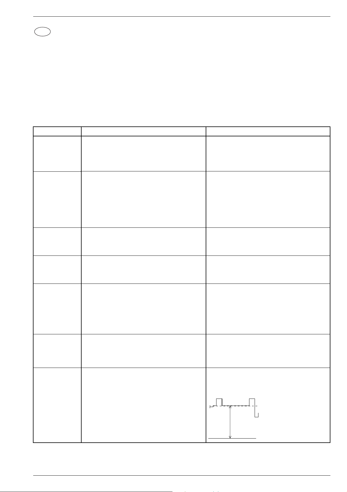
M 1000 / M 1001 Abgleich / Alignment / Alignement
100V…105V (14")
150V…155V (21")
D
Abgleich
Alle nicht beschriebenen Einstellelemente sind werkseitig abgeglichen und dürfen im Service-Fall nicht verstellt werden.
Chassisplatte
Meßgeräte: Digitalvoltmeter, Farbbildgenerator, Spektrumanalyser, HF-Millivoltmeter
Servicearbeiten nach Austausch bzw. Reparatur:
- Netzteil: Abgleich 1.
- Tuner: Abgleich 2.
- ZF, Videodemodulator: Abgleich 2.
- Bildröhre, Bildrohrplatte: Abgleich 5…7.
- Zeilenablenkung: Abgleich 6., 7.
- NVM IC82005: Abgleich 2…5., 8…9.
Abgleich Vorbereitung Abgleichvorgang
1. +A Spannung
2. Tuner-AGC
3. OSD
4. Tube
(Bildröhrentyp)
5. Weißwert
Nach jeder Reparatur und vor jedem Abgleich kontrollieren
und gegebenenfalls einstellen.
Helligkeit: Minimum
Digitalvoltmeter: Kathode D61016
Spektrumanalyser oder HF-Millivoltmeter unsymmetrisch
an Tunerkontakt 10, 11.
Senderbild oder Generator über die Antenne einspeisen,
70…80dBµV.
Dialogzeile "AGC" über Taste "M" (TV Menü)
–> Einstellungen –> "OK" –> Sonderfunktionen –> "OK"
Service –> "OK" –> Service Code –> "8640" aufrufen.
Dialogzeile "OSD" über Taste "M" (TV Menü)
–> Einstellungen –> "OK" –> Sonderfunktionen –> "OK"
Service –> "OK" –> Service Code –> "8640" aufrufen.
Dialogzeile "Tube" über Taste "M" (TV Menü)
–> Einstellungen –> "OK" –> Sonderfunktionen –> "OK"
Service –> "OK" –> Service Code –> "8640" aufrufen.
Schwarzweiß-Grautreppe mit Burst einspeisen.
Kontrast Maximum.
Farbkontrast Mittelwert.
Bildschirmhelligkeit Mittelwert.
Dialogzeile "WHITE ADJUSTMENT" über "M" (TV Menü)
–> Einstellungen –> "OK" –> Sonderfunktionen –> "OK"
Service –> "OK" –> Service Code –> "8640" –> "OK" aufrufen.
R60037 nach Tabelle im Teilschaltplan Netzteil einstellen.
Mit der Taste i oder u 102dBµV (360mVss) einstellen.
Ersatzweise wird ohne Spektrumanalyser oder HF-Milli-
voltmeter mit der Taste i oder u das Bild so abgestimmt,
daß es gerade zu rauschen beginnt. Dann soweit zurückstellen, bis das Bild wieder rauschfrei wird.
Dialogzeile "Ende" mit "with mem." beenden.
Mit der Taste i oder u das Menü in die Bildmitte stellen.
Dialogzeile "Ende" mit "with mem." beenden.
Mit der Taste i oder u die richtige Bildschirmdiagonale
eingeben.
Dialogzeile "Ende" mit "with mem." beenden.
Mit der Taste i oder u die Werte für "Grün" bzw. "Blau" so
einstellen, daß das Testbild unbunt wird.
Kontrolle des Weißabgleichs mit Kontrast Minimum und
Maximum.
Mit Taste "M" zurück ins SERVICE- Menü und Dialogzeile
"Ende" mit "with mem." beenden.
6. Zeilenschärfe
7. Schirmgitterspannung U
LOEWE.-Service 2 - 1
Konvergenztestbild einspeisen.
Kontrast Maximum.
Bildschirmhelligkeit so einstellen, daß der schwarze Testbildhintergrund sich gerade aufzuhellen beginnt.
Graubalken-Testbild einspeisen.
Bildschirmhelligkeit so einstellen, daß die Abstufung vom
G2
dunkelsten Graubalken zu schwarz gerade noch sichtbar
ist.
Mittlerer Kontrast.
An den Meßpunkten R, G, B (auf der Bildrohrplatte)
Oszilloskop anschließen und den höchsten Schwarzwertpegel ermitteln.
Mit dem Focusregler UF die vertikalen Linien ca. 5cm vom
rechten und linken Bildrand auf kleinste horizontalen Breite einstellen.
Die Mittenschärfe darf nicht schlechter als die Randschärfe
erscheinen, ggf. mitteln.
Mit Regler UG2 an dem Meßpunkt mit dem höchsten Schwarzwert eine Spannung von 100V…105V für 14" und
150V…155V für 21" Bildröhren abgleichen.
Schwarzwert
105-110V
Page 22
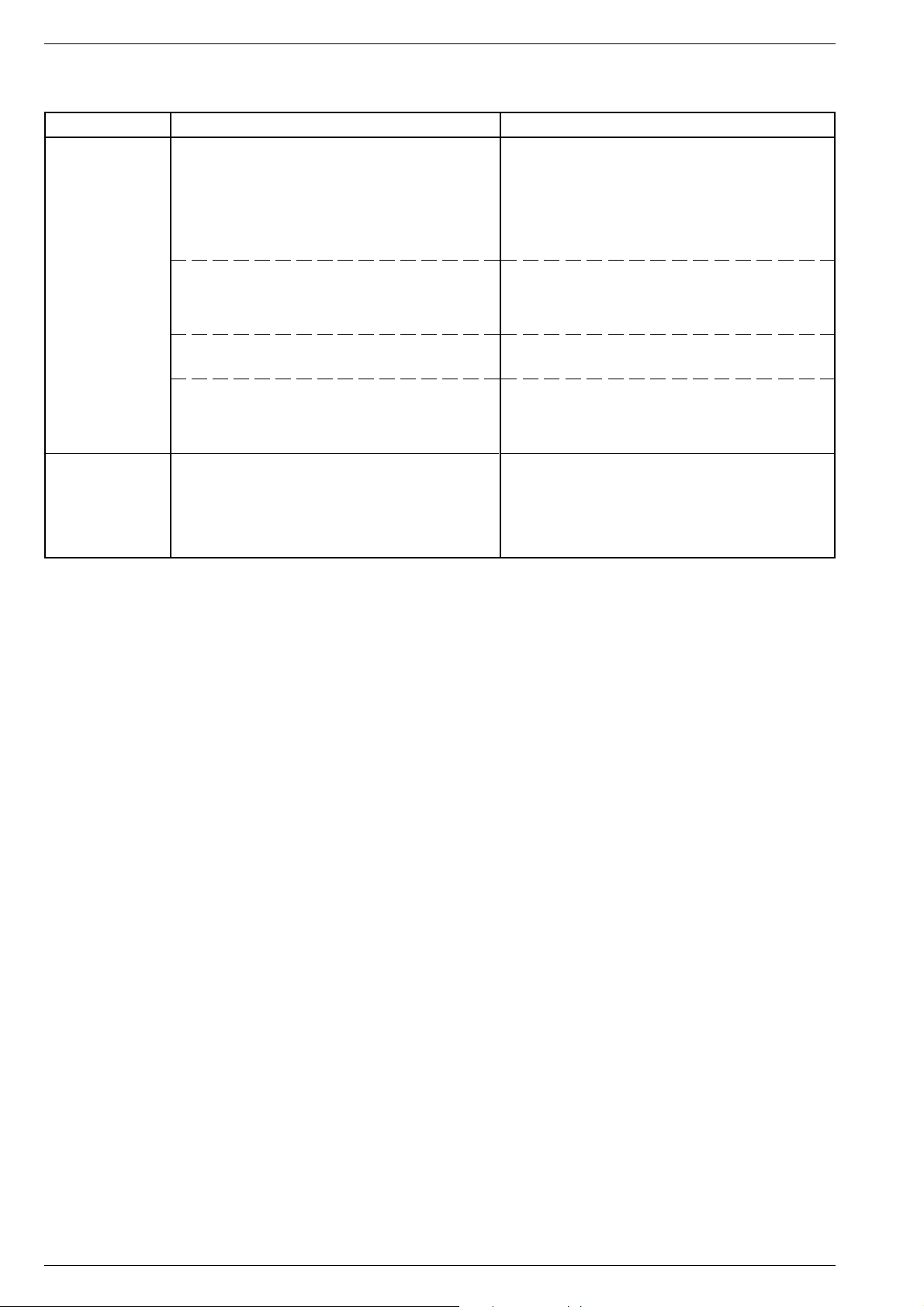
Abgleich / Alignment / Alignement M 1000 / M 1001
Geometrieeinstellung in betriebswarmem Zustand (ca. 15 Min.), mit dem Abgleich Mittelpunkt S-Korrektur (Vertikal Slope) beginnen und Reihenfolge
einhalten!
Abgleich Vorbereitung Abgleichvorgang
8. Mittelpunkt
S-Korrektur
(Vertical Slope)
8.1 Vertikale
Bildlage
(Vertical Correkt.)
8.2 Vertikalamplitude
8.3 Vertikale
Linearität
9. Horizontale
Bildlage
(Horizontal
Shift)
Geometriebild einspeisen.
Menü "Vertical Slope" über Taste "M" (TV Menü)
–> Einstellungen –> "OK" –> Sonderfunktionen –> "OK"
Service –> "OK" –> Service Code –> "8640" –>
"GEOMETRIE" –> "OK" aufrufen.
Menü "Vertical Correkt." aufrufen.
Menü "Vertical Amplitude" aufrufen.
Menü "Vertical Linearit." aufrufen.
Geometriebild einspeisen.
Menü "Horizontal Shift" über Taste "M" (TV Menü)
–> Einstellungen –> "OK" –> Sonderfunktionen –> "OK"
Service –> "OK" –> Service Code –> "8640" –>
"GEOMETRIE" –> "OK" aufrufen.
Die Mittellinie des Testbildes in der Dialogzeile "Vertical
Slope" mit den Tasten i oder u so abgleichen, daß sie
gerade noch sichtbar ist.
Falls nach erfolgtem Geometrie-Abgleich am unteren oder
oberen Bildrand Linearitätsfehler auftreten, Einstellung leicht
korrigieren.
Mit der Taste i oder u mittlere Gitterlinie auf Bildschirmmitte einstellen.
Mit der Taste i oder u Bildamplitude einstellen.
Mit der Taste i oder u nach Testbild einstellen.
Mit Taste "M" zurück ins Menü "SERVICE" und
Dialogzeile "Ende" mit "with mem." beenden.
Mit der Taste i oder u nach Testbild einstellen.
Dialogzeile "Ende" mit "with mem." beenden.
2 - 2 LOEWE.-Service
Page 23

M 1000 / M 1001 Abgleich / Alignment / Alignement
GB
Alignment
All adjustment controls not mentioned in this description are pre-set at the factory and must not be re-adjusted in the case of repairs.
Chassis Board
Measuring instruments: Digital voltmeter, colour video generator, spectrum analyser, RF millivoltmeter
Service works after replacement or repair of the following modules:
- Power supply: alignment 1.
- Tuner: alignment 2.
- IF, video demodulator: alignment 2.
- CRT, CRT panel: alignment 5…7.
- Deflection: alignment 6., 7.
- NVM IC82005: alignment 2…5., 8…9.
Alignment Preparations Alignment Process
1. +A voltage
2. Tuner AGC
3. OSD
4. Tube
(Type of picture
tube)
5. White Balance
This voltage must be checked and re-adjusted if necessary
after every repair and before every alignment.
Brightness: Minimum
Digital voltmeter: Cathode D61016
Spectrum analyser or RF millivoltmeter unsymmetrical to
tuner contact 10, 11.
Feed in a standard test pattern or generator via the aerial,
70…80dBµV.
Call up the dialog line "AGC" via button "M" (TV-menu)
–> Settings –> "OK" –> Special functions –> "OK" –>
SERVICE –> "OK" –> Service Code –> "8640".
Call up the dialog line "OSD" via button "M" (TV-menu)
–> Settings –> "OK" –> Special functions –> "OK" –>
SERVICE –> "OK" –> Service Code –> "8640".
Call up the dialog line "Tube" via button "M" (TV-menu)
–> Settings –> "OK" –> Special functions –> "OK" –>
SERVICE –> "OK" –> Service Code –> "8640".
Feed in a grey scale black/white test pattern with burst.
Contrast to maximum.
Colour contrast to mid-position.
Screen brightness to mid-position.
Call up dialog line "WHITE ADJUSTMENT" via button "M"
(TV-menu) –> Settings –> "OK" –> Special functions –> "OK"
–> SERVICE –> "OK" –> Service Code –> "8640".
Adjust R60037 acc. to the table on the circuit diagram
mains section.
Adjust 102dBµV (360mVpp) with button i or u.
Alternatively, without using a spectrum analyser or RF
millivoltmeter, adjust the picture with button i or u so that
noise just appears on the screen. Then reset until the
picture is again free of noise.
Terminate the dialog line "End" "with mem.".
With button i or u position the menu in the middle of the
picture.
Terminate the dialog line "End" "with mem.".
With button i or u enter the correct screen diagonal.
Terminate the dialog line "End" "with mem."
With button i or u set the values for "Green" and "Blue"
so that the picture becomes achromatic.
Check this alignment at minimum and maximum contrast.
Go back to the "SERVICE" menu with "M" and terminate
the dialog line "End" "with mem.".
6. Line Sharpness
7. Screen grid
voltage U
LOEWE.-Service 2 - 3
G2
Feed in a convergency test pattern.
Contrast to maximum.
Set the screen brightness so that the black
background of the test pattern just starts to brighten.
Feed in a grey scale test pattern.
Adjust the screen brightness so that the gradation from the
darkest grey scale value to black is just still visible.
Set the contrast to mid-value.
Measure test points R, G, B (on the CRT panel) to determine
the test point with the highest black level and connect this
point to the oscilloscope.
With focus control UF, adjust the vertical lines approx.
5cm from the right and left picture edge to minimum
horizontal width.
The sharpness in the middle must not seem to be worse
than the sharpness at the edges. If necessary, take an
average.
With the control UG2 adjust the black level at the test point
with the highest black level to approx. 100V…105V for 14"
picture tubes and 150V…155V for 21" picture tubes.
Black level
105-110V
100V…105V (14")
150V…155V (21")
Page 24

Abgleich / Alignment / Alignement M 1000 / M 1001
Allow the TV to warm up (approx. 15 min.) before setting the geometry, start with alignment Centre S-Correction (Vertical Slope) and continue in
the correct order.
Alignment Preparations Alignment Process
8. Centre
S-Correction
(Vertical Slope)
8.1 Vertical position
of the picture
(Vertical
Correct.)
8.2 Vertical
Amplitude
8.3 Vertical
Linearity
9. Horizontal Shift
Feed in a geometry test pattern.
Call up the "Vertical Slope" menu via button "M" (TVmenu) –> Settings –> "OK" –> Special functions –> "OK"
–> SERVICE –> "OK" –> Service Code –> "8640".–>
"GEOMETRIE" –> "OK".
Call up the menu "Vertical Correct."
Call up the menu "Vertical Amplitude".
Call up the menu "Vertical Linearit.".
Feed in a geometry test pattern.
Call up dialog line "Horizontal Shift" via button "M" (TVmenu) –> Settings –> "OK" –> Special functions –> "OK"
–> SERVICE –> "OK" –> Service Code –> "8640".–>
"GEOMETRIE" –> "OK".
Adjust the center line of the test pattern in the dialog line
"Vertical Slope" with button i or u so that it is just still visible.
Should linearity errors appear in the lower or upper edge of
the picture after having adjusted the geometry, correct the
setting slightly.
Position the center line of the grid so that it is in the middle
of the screen using button i or u.
Set the vertical amplitude using button i or u.
Adjust according to the test pattern using button i or u.
Go back to the "SERVICE" menu with "M" and terminate
the dialog line "End" "with mem.".
Adjust according to the test pattern using button i or u.
Terminate the dialog line "End" "with mem.".
2 - 4 LOEWE.-Service
Page 25

M 1000 / M 1001 Abgleich / Alignment / Alignement
Alignment
F
Tous les éléments de réglage non décrits ont été mis au point en usine et n'ont plus à être repris en maintenance.
C.I. Châssis
Appareils de mesure: Générateur de mire couleur, Voltmètre numérique, Analyseur de spectre ou Millivoltmètre HF
Travaux de maintenance suite au remplacement ou à la réparation de:
- Alimentation: Alignement 1.
- Tuner: Alignement 2.
- FI, Démodulateur vidéo: Alignement 2.
- Tube image, C.I. Tube: Alignement 5…7.
- Déviation horizontale: Alignements 6., 7.
- NVM IC82005: Alignements 2…5., 8…9.
Alignement Préparation Procédure de réglage
1. Tension +A
2. Tuner-CAG-HF
3. OSD
4. Tube
(Type de tube)
5. Balance du
blanc
Après chaque réparation et avant chaque alignement
contrôler et au besoin régler cette tension.
Luminosité: minimum
Voltmètre numérique: cathode D61016.
Relier l'analyseur de spectre ou le millivoltmètre HF
symétriquement aux contacts 10, 11 du tuner.
Injecter une mire normalisée ou le générateur de mire
couleur via l'antenne, 70…80dBµV.
Appeler la ligne de dialogue "CAG-HF" via la touche "M"
(Menu TV) –> Paramètres –> "OK" –> Fonctions spéciales
–> "OK" –> SERVICE –> "OK" –> Code service –> "8640".
Appeler la ligne de dialogue "OSD" via la touche "M" (Menu
TV) –> Paramètres –> "OK" –> Fonctions spéciales –>
"OK" –> SERVICE –> "OK" –> Code service –> "8640".
Appeler la ligne de dialogue "Tube" via la touche "M" (Menu
TV) –> Paramètres –> "OK" –> Fonctions spéciales –> "OK"
–> SERVICE –> "OK" –> Code service –> "8640".
Injecter une échelle des gris (noir/blanc) avec Burst.
Contraste maximum.
Saturation couleur moyenne.
Luminosité moyenne.
Appeler la ligne de dialogue "WHITE ADJUSTMENT"
(balance du blanc) via la touche "M" (Menu TV)
–> Paramètres –> "OK" –> Fonctions spéciales –> "OK" –>
SERVICE –> "OK" –> Code service –> "8640".
Régler R60037 à la valeur indiquée au tableau sur le
schéma partiel du circuit d'alimentation.
A l'aide des touches i ou u régler la tension à102dBµV
(360mVcc).
En variante, sans analyseur de spectre ou sans
millivoltmètre HF, à l'aide des touches i ou u régler l'image
jusqu'à l'apparition du souffle. Puis revenir afin d'obtenir
une image à la limite du souffle.
Appeler la ligne de dialogue "Fin" et valider "with mem."
(avec mémorisation).
A l'aide des touches i ou u positionner le menu au milieu
de l'écran.
Appeler la ligne de dialogue "Fin" et valider "with mem."
(avec mémorisation).
A l'aide des touches i ou u sélectionner la diagonaleimage correcte.
Appeler la ligne de dialogue "Fin" et valider "with mem."
(avec mémorisation).
A l'aide des touches i ou u régler les valeurs du "Vert" ou
du "Bleu" de façon à obtenir une image-test sans dominante de couleur.
Effectuer le contrôle de la balance du blanc avec le contraste
minimum et maximum.
Revenir au menu SERVICE par la touche "M" et sortir par
la ligne de dialogue "Fin" et valider " with mem " (avec
mémorisation).
6. Netteté ligne
7. Réglage de la
tension de
grille U
G2
LOEWE.-Service 2 - 5
Injecter une mire de convergence
Contraste au maximum
Régler la luminosité de sorte à ce que le fond noir de la mire
commence juste à s'éclaircir.
Injecter une mire de barre de gris.
Régler la luminosité de l'écran de façon que la zone des gris
devienne juste sombre.
Contraste moyen.
Mesurer les points de réglages R, V, B (sur le C.I. tube) pour
déterminer le point de mesure ayant le niveau de noir le plus
élevé et relier la sonde de l'oscilloscope à ce point.
Régler ensuite les lignes verticales à 5 cm du bord gauche
et du bord droit de l'écran sur la largeur horizontale la plus
fine possible à l'aide du pot. focus UF.
A l'aide de l'ajustable UG2 régler le niveau du noir du point de
réglage le plus élevé à env. 100V…105V pour les tubes de
14" et 150V…155V pour ceux de 21".
Niveau du noir
105-110V
100V…105V (14")
150V…155V (21")
Page 26

Abgleich / Alignment / Alignement M 1000 / M 1001
Commencer le réglage de géométrie avec l'alignement correction S centre (" Vertical Slope ") à chaud (env. 15 min.) et respecter strictement l’ordre
des instructions !
Alignement Préparation Procédure de réglage
8. Correction S
centre
(Déviation
verticale)
8.1 Correction
verticale
(vue
verticalement)
8.2 Amplitude
verticale
8.3 Linéarité
verticale.
9. Déviation
horizontale
Injecter une mire géométrique de réglage.
Appeler le menu "Déviation verticale" via la touche "M"
(Menu TV) –> Paramètres –> "OK" –> Fonctions spéciales
–> "OK" –> SERVICE –> "OK" –> Code service –> "8640"
–> "GEOMETRIE".
Appeler le menu "correction verticale"
Appeler le menu "Vertical Amplitude"
Appeler le menu "Vertical Linearit"
Injecter une mire géométrique de réglage.
Appeler le menu "Déviation horizontale" via la touche "M"
(Menu TV) –> Paramètres –> "OK" –> Fonctions spéciales
–> "OK" –> SERVICE –> "OK" –> Code service –> "8640"
–> "GEOMETRIE".
Régler la ligne médiane de la mire dans la ligne de dialogue
"Déviation verticale" à l'aide des touches i ou u de façon
qu'elle soit juste encore visible.
Affiner le réglage si un défaut de linéarité apparaît au bord
supérieur au inférieur de I'écran lors de la correction
géométrique.
Régler les lignes centrales de grille vers le centre de l’écran
à l’aide des touches i ou u.
Régler l’amplitude image à l’aide des touches i ou u.
Régler l’image test à l’aide des touches i ou u.
Retourner au menu SERVICE avec la touche "M" et terminer
par la ligne de dialogue "Fin" et valider " with mem. " (avec
mémorisation).
Régler I'image à l'aide des touches i ou u suivant la mire.
Appeler la ligne de dialogue "Fin" et valider "with mem."
(avec mémorisation).
2 - 6 LOEWE.-Service
Page 27

M 1000 / M 1001 Platinenabbildungen und Schaltpläne / Layout of the PCBs and Circuit Diagrams / Circuits imprimés et des schémas électriques
Platinenabbildungen und Schaltpläne / Layout of the PCBs and Circuit Diagrams /
Circuits imprimés et schémas électriques
Chassisplatte
Koordinaten für die Bauteile der
Bestückungsseite (Oberseite)
Pos.-Nr./ Koordinaten/
Pos. No./ Coordinates/
Pos. N°/ Coordonnées
XY
BR101 104 103
BR102 231 47
BR103 147 68
BR104 126 44
BR107 87 154
BR108 166 114
BR109 191 141
BR110 43 111
BR111 44 96
BR112 38 111
BR113 51 122
BR114 135 16
BR115 228 36
BR116 164 113
BR117 169 116
BR118 174 105
BR119 103 135
BR120 131 136
BR121 172 124
BR123 164 179
BR125 156 49
BR126 184 144
BR127 121 46
BR129 57 123
BR130 59 104
BR131 58 106
BR132 48 122
BR133 235 131
BR134 166 133
BR135 111 106
BR136 93 111
BR137 197 128
BR139 98 65
BR140 138 100
BR141 186 171
BR142 73 96
BR143 53 149
BR144 103 158
BR146 117 144
BR147 156 34
BR149 27 79
BR150 26 72
BR151 133 136
BR152 140 79
BR153 18 52
BR154 87 10
BR155 228 141
BR156 122 165
BR157 88 222
BR158 138 226
BR159 253 184
BR161 244 109
BR162 156 116
BR163 230 139
BR164 238 135
BR165 215 133
BR166 141 128
BR167 9 58
BR168 169 188
BR169 173 199
BR170 71 240
BR171 136 59
BR173 118 80
BR174 58 95
BR175 169 136
BR177 182 118
BR178 246 101
BR179 254 181
BR180 79 210
BR181 53 77
BR182 241 81
BR184 228 26
BR185 228 33
BR186 173 38
BR187 206 56
BR188 227 29
BR189 226 23
BR190 228 39
BR191 224 20
BR192 49 16
BR194 210 10
BR196 225 171
BR197 240 79
BR198 248 163
BR199 194 123
BR200 199 140
BR201 43 98
BR202 109 81
Pos.-Nr./ Koordinaten/
Pos. No./ Coordinates/
Pos. N°/ Coordonnées
BR203 67 96
BR204 94 144
BR205 153 146
BR206 93 45
BR207 189 79
BR210 46 203
BR211 186 90
BR216 70 96
BR218 43 73
BR220 27 75
BR221 65 96
BR222 161 114
BR224 79 42
BR225 78 104
BR226 76 104
BR228 174 122
BR229 101 139
BR230 88 140
BR233 19 63
BR234 95 28
BR235 71 81
BR236 32 127
BR237 59 21
BR238 177 132
BR239 159 113
BR242 70 64
BR244 56 60
BR245 23 138
BR246 91 136
BR247 211 68
BR249 26 139
BR251 163 88
BR252 162 75
BR253 219 102
BR255 83 175
BR257 71 140
BR258 72 145
BR261 82 139
BR262 140 29
BR263 141 50
BR264 54 16
BR265 169 13
BR266 79 26
BR267 126 25
BR268 194 10
BR269 184 26
BR271 154 27
BR272 61 18
BR273 115 11
BR274 114 15
BR275 153 136
BR276 208 123
BR278 207 120
BR279 179 62
BR280 146 49
BR31045 39 29
BR32108 98 112
BR32492 20 60
BR34033 162 72
BR40054 108 35
BR43071 150 79
BR43072 147 79
BR43073 153 78
BR50031 61 167
BR52006 14 162
BR53011 23 202
BR53016 90 193
BR53021 52 191
BR53074 72 195
BR60001 136 208
BR60012 151 220
BR60021 210 173
BR61016 103 242
BR61037 106 225
BR61040 123 154
BR61050 184 128
BR62501 206 241
BR62502 192 217
BR62503 205 217
BR62504 221 230
BR62505 221 220
BR80001 237 144
BR80002 247 137
BR80303 147 121
BR80315 214 53
BR80316 212 51
BR81002 267 183
XY
Chassis Board
Coordinates of the Components on
the Components Side (Top Side)
Pos.-Nr./ Koordinaten/
Pos. No./ Coordinates/
Pos. N°/ Coordonnées
XY
BR81030 193 93
BR81042 167 64
BR81051 206 101
BR81052 209 101
BR81053 212 101
BR81504 76 204
BR81512 243 166
BR84001 236 88
BR84002 236 85
BR84003 158 58
BR84004 169 42
BU01 268 66
C31042 47 29
C31044 55 29
C31046 15 55
C32011 62 81
C32023 69 117
C32024 76 128
C32206 196 51
C32438 35 94
C32494 33 53
C32496 47 53
C32498 41 53
C32499 27 57
C32521 38 75
C32522 35 83
C33019 132 56
C34021 108 98
C34063 79 76
C34071 78 92
C40001 178 26
C40021 147 36
C40022 199 25
C40031 190 25
C40057 134 38
C40061 104 25
C40062 116 23
C43249 10 128
C44022 246 57
C44032 241 52
C46001 167 81
C50022 58 146
C50023 61 140
C50031 52 168
C50032 64 158
C52001 48 161
C52002 38 145
C52003 40 168
C52004 13 157
C52006 38 157
C52247 110 63
C52253 111 56
C52254 98 69
C53001 38 197
C53002 27 188
C53006 32 180
C53011 9 205
C53017 68 250
C53031 68 215
C53032 73 215
C54001 86 166
C54011 94 212
C54012 49 140
C54031 87 180
C54032 70 167
C57016 9 133
C60001 127 214
C60002 186 188
C60007 150 198
C60009 154 237
C60011 167 198
C60013 176 198
C60022 147 179
C60023 192 181
C60024 190 163
C60026 190 174
C60027 203 168
C60037 191 190
C60038 174 240
C61015 106 236
C61016 103 251
C61017 86 243
C61036 109 205
C61037 117 187
C61042 109 144
C61052 143 145
C61056 109 178
Pos.-Nr./ Koordinaten/
Pos. No./ Coordinates/
Pos. N°/ Coordonnées
C61057 118 172
C61063 176 146
C61065 131 159
C62021 236 174
C62022 236 180
C62048 123 202
C62501 198 232
C62502 210 203
C62505 219 187
C80011 272 174
C81061 191 100
C81063 194 106
C84001 244 159
D40012 223 55
D40022 149 49
D40060 66 18
D40061 69 16
D40062 71 19
D40063 90 30
D40064 86 29
D40065 156 10
D43055 22 110
D43056 20 119
D43071 150 79
D43072 147 79
D43073 153 78
D50022 57 139
D50023 72 148
D50026 56 165
D50027 59 124
D52001 42 171
D53003 55 194
D54001 89 209
D54011 98 210
D54021 92 184
D54022 69 31
D54031 83 178
D57011 13 140
D57013 17 140
D57023 139 96
D57122 14 154
D60006 156 220
D60007 149 209
D60012 156 203
D60022 195 168
D60023 195 168
D60024 205 160
D60026 206 171
D60027 199 171
D60037 175 229
D61016 103 240
D61036 109 206
D61037 108 207
D61056 106 181
D81054 216 112
D81123 156 100
D81501 244 186
D84001 278 184
D84003 253 161
D85001 272 194
D85002 274 194
EURO-AV01 6 93
F32101 85 127
F32109 94 122
F32121 122 114
F32162 81 101
F32167 81 111
F32410 70 42
F32412 94 55
F32420 61 53
F32430 56 72
F32493 29 64
IC32490 43 64
IC32520 49 83
IC34015 109 80
IC40001 181 16
IC40050 142 19
IC50010 60 154
IC60010 176 188
IC61040 108 153
IC61050 141 153
IC61060 173 153
IC80000 192 55
IC80010 277 173
IC80020 282 173
IC81050 194 80
IC81210 196 37
XY
C.I. principal
Coordonnées des composants côté
composants (Vue de dessus)
Pos.-Nr./ Koordinaten/
Pos. No./ Coordinates/
Pos. N°/ Coordonnées
XY
IC82005 225 78
KBL01 142 23
KH01 269 36
KH02 273 85
L+ 264 139
L- 264 154
L31043 38 29
L32023 73 123
L32026 64 117
L32108 98 111
L32109 90 112
L32151 99 100
L32201 30 88
L40012 98 29
L41011 258 36
L41111 261 94
L46021 198 99
L53003 20 195
L53011 23 202
L53021 50 181
L53074 72 193
L60006 159 237
L60012 151 220
L61016 103 242
L61036 106 223
L61038 119 159
L61056 97 232
L62501 199 217
L62502 199 217
L81061 191 123
NETZ01 233 233
NETZ02 225 233
P+ 264 106
P- 264 121
Q34043 122 63
Q34044 128 63
Q80001 194 64
R32132 97 119
R32403 33 110
R32406 35 111
R32407 30 110
R32408 28 110
R33019 163 92
R34051 145 107
R34052 146 111
R34053 146 114
R34054 75 85
R34055 73 88
R34056 121 100
R34057 125 98
R34058 128 98
R34059 132 99
R34063 91 95
R34071 56 95
R34073 144 78
R40051 117 41
R40053 116 30
R40054 108 35
R40072 139 10
R43001 24 28
R43014 18 20
R43019 26 82
R43020 19 66
R43248 23 121
R44011 118 101
R44013 111 125
R44014 142 131
R46003 191 110
R50016 54 122
R50017 46 120
R50018 49 132
R50022 58 165
R50023 74 159
R50032 69 176
R50046 72 143
R50047 70 138
R52001 42 164
R52002 10 176
R52004 27 157
R52006 14 162
R53002 51 197
R53009 17 175
R53011 18 198
R53016 89 194
R53021 52 191
R53033 86 226
R53034 86 215
Pos.-Nr./ Koordinaten/
Pos. No./ Coordinates/
Pos. N°/ Coordonnées
R53074 73 208
R54001 84 232
R54006 88 219
R54022 84 156
R54031 77 218
R57118 30 148
R60001 177 170
R60002 172 170
R60003 167 170
R60004 171 181
R60006 170 218
R60007 182 170
R60008 151 206
R60009 152 214
R60012 162 192
R60013 180 199
R60016 175 226
R60021 212 170
R60029 181 221
R60037 188 200
R61018 98 242
R61043 120 142
R61046 97 142
R61053 132 148
R62049 122 209
R62505 205 187
R80013 256 137
R81001 256 172
R81004 258 173
R81020 190 112
R81041 176 43
R81054 215 98
R81088 186 90
R81126 159 99
R81222 228 117
R81226 230 116
R81506 166 39
R84004 241 112
S62501 242 209
SCL01 24 95
SCL02 182 41
SDA01 24 98
SDA02 185 41
SI40051 110 48
SI52001 37 138
SI60001 136 205
SI61056 100 224
SI62501 206 241
ST-A01 90 14
ST-A02 30 14
ST-ASIS04 169 10
ST-ASIS05 204 45
ST-ASIS01 210 129
ST-ASIS03 236 99
ST-ASIS02 149 64
ST-BAT01 167 31
ST-BAT02 71 243
ST-BAT04 56 201
ST-BAT03 210 137
ST-BR 96 169
ST-E 219 170
ST-H 214 31
ST-HOSP02 11 28
ST-HOSP01 166 52
ST-IR-KB 264 179
ST-JOCH 68 181
ST-LH01 130 198
ST-LH02 136 197
ST-LS 207 18
ST-LS-L 194 16
ST-LS-R 168 19
ST-M-LED 262 196
ST-NETZ02 229 241
ST-RGB 135 114
ST-RGB02 18 97
ST-V02 185 57
ST-V03 156 127
ST-V04 127 128
T52001 42 157
T53001 9 189
T60006 172 212
T81501 244 126
TR52001 29 167
TR53000 37 227
TR53010 36 230
TR53020 39 227
TR61000 129 233
TUNER 29 42
XY
LOEWE.-Service 3 - 1
Page 28

Platinenabbildungen und Schaltpläne / Layout of the PCBs and Circuit Diagrams / Circuits imprimés et des schémas électriques M 1000 / M 1001
Chassisplatte
Koordinaten für die Bauteile
der Lötseite (Unterseite)
Pos.-Nr./ Koordinaten/
Pos. No./ Coordinates/
Pos. N°/ Coordonnées
XY
CBR30 73 77
CBR100 208 53
CBR101 70 47
CBR102 179 107
CBR104 139 108
CBR105 75 73
CBR107 70 69
CBR108 80 100
CBR110 37 59
CBR111 97 69
CBR112 254 165
CBR114 106 81
CBR116 20 42
CBR117 16 49
CBR121 213 84
CBR123 73 73
CBR124 25 115
CBR125 20 55
CBR126 55 81
CBR127 34 88
CBR129 116 126
CBR130 40 102
CBR131 66 80
CBR132 48 87
CBR133 24 132
CBR134 25 113
CBR135 54 114
CBR136 52 61
CBR140 20 115
CBR141 24 129
CBR142 57 108
CBR144 35 129
CBR145 145 116
CBR147 29 142
CBR150 221 91
CBR151 173 96
CBR152 271 193
CBR183 159 53
CBR208 186 86
CBR209 181 85
CBR32111 107 128
CBR32490 40 76
CBR57000 9 141
CBR81004 186 129
CBR81005 216 84
CBR81011 206 88
CBR81012 212 88
CBR81013 218 84
CBR84009 162 131
CBR84011 195 32
CBR84012 206 84
CBR84013 132 25
CBR84015 111 65
CBR84016 223 126
CBR84018 210 131
CBR84019 28 132
CC31019 27 51
CC31047 15 52
CC31048 16 42
CC31051 30 51
CC31052 33 51
CC32026 71 127
CC32106 98 131
CC32110 95 131
CC32111 90 117
CC32118 80 136
CC32121 125 130
CC32124 119 131
CC32151 72 123
CC32152 90 110
CC32201 26 84
CC32202 30 90
CC32401 42 105
CC32412 66 54
CC32488 51 56
CC32491 52 68
CC32492 35 76
CC32493 33 69
CC32495 37 57
CC32497 28 58
CC32499 37 69
CC32523 57 89
CC33014 92 103
CC33015 103 98
CC33016 89 97
CC33017 95 99
CC33018 86 71
CC33020 89 71
CC33021 86 81
CC33022 88 74
CC34001 86 54
CC34022 108 102
CC34027 122 82
CC34032 133 73
CC34037 116 73
CC34039 112 97
CC34041 125 82
CC34042 136 81
CC34043 119 67
Pos.-Nr./ Koordinaten/
Pos. No./ Coordinates/
Pos. N°/ Coordonnées
CC34044 125 67
CC34061 107 98
CC34062 116 97
CC34064 99 97
CC34067 100 90
CC34069 85 97
CC34072 83 73
CC34073 73 80
CC34075 131 103
CC34079 144 108
CC34080 123 102
CC40002 177 21
CC40011 128 31
CC40012 182 21
CC40023 141 43
CC40032 189 26
CC40038 139 16
CC40049 155 20
CC40056 145 33
CC40062 143 17
CC40063 141 33
CC40071 140 20
CC40072 147 20
CC40098 219 19
CC40099 122 56
CC41009 258 42
CC41011 261 48
CC41012 252 49
CC41013 17 13
CC41014 241 34
CC41112 260 96
CC41113 255 95
CC41116 263 95
CC43003 16 86
CC43008 16 83
CC43013 10 70
CC43018 14 76
CC43057 148 81
CC43058 145 81
CC43061 151 81
CC43248 10 132
CC44021 254 65
CC44031 248 57
CC46004 224 119
CC46014 181 88
CC46015 178 88
CC46016 172 88
CC46017 190 98
CC46021 192 88
CC46022 198 88
CC46023 180 81
CC46025 194 88
CC46026 167 69
CC46027 176 84
CC50011 102 81
CC50012 97 84
CC50013 53 162
CC50018 49 162
CC50021 56 162
CC50026 62 155
CC50047 69 168
CC52246 108 73
CC52248 113 73
CC52266 186 121
CC54021 87 157
CC57003 94 84
CC57004 8 154
CC57016 9 144
CC57021 114 90
CC60014 183 195
CC60016 172 192
CC60031 193 195
CC60036 175 192
CC61038 111 155
CC61039 114 155
CC61041 111 151
CC61051 140 151
CC61058 150 157
CC61059 146 145
CC61060 147 157
CC61061 170 155
CC61062 179 154
CC61064 167 155
CC80001 195 65
CC80002 198 65
CC80003 192 65
CC80007 188 64
CC81007 187 109
CC81008 228 97
CC81012 183 81
CC81016 201 84
CC81020 182 111
CC81021 182 58
CC81023 203 64
CC81026 204 58
CC81028 204 61
CC81032 212 64
CC81033 173 107
CC81034 182 101
XY
Chassis Board
Coordinates of the components on
the Solder Side (Bottom Side)
Pos.-Nr./ Koordinaten/
Pos. No./ Coordinates/
Pos. N°/ Coordonnées
XY
CC81036 183 107
CC81037 181 65
CC81038 181 62
CC81041 183 41
CC81043 173 73
CC81046 215 64
CC81048 230 76
CC81050 224 123
CC81051 200 121
CC81052 207 112
CC81053 203 119
CC81054 215 106
CC81062 197 81
CC81072 210 106
CC81080 201 105
CC81081 221 101
CC81082 188 68
CC81088 173 82
CC81089 165 53
CC81211 201 42
CC82001 229 83
CC82004 226 83
CD32162 86 110
CD32167 86 117
CD32411 76 51
CD32421 97 58
CD32460 78 72
CD32465 86 65
CD32475 94 58
CD32495 30 58
CD80007 173 53
CIC32410 35 115
CR31021 25 51
CR31041 27 42
CR31043 41 39
CR31044 69 36
CR31046 15 55
CR31047 21 51
CR31051 23 43
CR31052 23 41
CR32011 60 91
CR32012 60 86
CR32023 85 123
CR32101 110 131
CR32102 95 118
CR32103 99 109
CR32104 107 130
CR32105 86 132
CR32106 101 131
CR32107 110 113
CR32108 93 116
CR32109 85 128
CR32110 87 123
CR32111 103 108
CR32112 106 134
CR32113 124 124
CR32114 124 126
CR32119 61 126
CR32124 123 130
CR32128 108 106
CR32133 114 126
CR32141 120 125
CR32142 118 125
CR32143 114 122
CR32150 108 134
CR32151 99 105
CR32160 84 110
CR32161 71 113
CR32162 73 113
CR32163 85 114
CR32167 84 117
CR32168 78 123
CR32201 176 48
CR32202 182 56
CR32203 183 52
CR32204 181 52
CR32206 200 56
CR32401 33 104
CR32402 30 104
CR32412 66 52
CR32420 99 58
CR32433 52 98
CR32436 49 98
CR32437 40 95
CR32438 37 94
CR32439 42 98
CR32451 75 69
CR32452 73 69
CR32453 78 61
CR32456 64 69
CR32457 67 69
CR32460 62 73
CR32462 67 75
CR32463 81 68
CR32464 83 63
CR32466 65 75
CR32467 90 58
CR32468 90 63
Pos.-Nr./ Koordinaten/
Pos. No./ Coordinates/
Pos. N°/ Coordonnées
CR32471 77 66
CR32472 70 58
CR32473 73 64
CR32476 70 53
CR32481 80 63
CR32482 75 64
CR32483 78 56
CR32486 73 53
CR32493 22 65
CR32494 37 62
CR32497 44 59
CR32498 49 68
CR32499 44 55
CR32501 68 80
CR32502 45 68
CR32521 52 88
CR32522 43 88
CR32523 40 89
CR32524 54 88
CR32525 69 84
CR32527 52 95
CR32528 48 90
CR33014 92 99
CR34031 125 63
CR34032 133 70
CR34042 133 81
CR34064 96 102
CR34066 104 89
CR34071 86 103
CR34072 146 94
CR34074 142 77
CR34075 126 102
CR34076 153 85
CR34077 137 93
CR34078 142 88
CR34079 142 108
CR34080 128 102
CR40011 185 21
CR40015 148 41
CR40016 144 44
CR40019 153 43
CR40022 161 40
CR40023 159 43
CR40026 135 15
CR40032 189 21
CR40038 136 20
CR40049 152 20
CR40052 105 48
CR40060 69 22
CR40061 66 23
CR40063 74 27
CR40064 63 13
CR40065 59 23
CR40068 74 20
CR40075 175 15
CR40076 200 19
CR40077 195 28
CR40078 191 24
CR40079 209 26
CR41008 261 44
CR41009 256 39
CR41011 255 42
CR41014 261 39
CR41016 217 48
CR41017 254 49
CR41018 252 95
CR41116 263 95
CR43003 20 87
CR43004 17 76
CR43008 16 80
CR43013 9 76
CR43017 20 81
CR43018 11 76
CR43056 20 124
CR43057 148 85
CR43058 146 85
CR43061 151 85
CR43062 5 107
CR43063 10 109
CR43066 5 100
CR43067 5 92
CR43071 22 98
CR43072 22 91
CR43073 153 81
CR43075 21 106
CR43241 13 119
CR43242 11 123
CR43243 15 119
CR43246 15 128
CR43247 10 119
CR43267 17 119
CR43268 21 94
CR44012 130 125
CR44021 254 60
CR44031 253 56
CR46001 184 90
CR46004 221 106
CR46007 219 118
CR46008 229 119
XY
C.I. principal
Coordonnées des composants
côté soudures (Vue de dessous)
Pos.-Nr./ Koordinaten/
Pos. No./ Coordinates/
Pos. N°/ Coordonnées
XY
CR46009 208 127
CR46011 227 119
CR46012 221 117
CR46013 218 106
CR46016 175 88
CR46022 173 79
CR46023 173 85
CR46024 169 89
CR46026 170 73
CR50011 96 81
CR50012 91 83
CR50019 69 153
CR52247 110 73
CR52251 115 81
CR52252 91 73
CR52254 97 72
CR52261 113 81
CR52262 99 84
CR52264 32 142
CR52266 183 121
CR53008 14 167
CR54021 91 161
CR57001 20 146
CR57002 35 137
CR57003 11 154
CR57004 23 141
CR57008 13 146
CR57011 15 146
CR57012 18 146
CR57016 20 141
CR57017 132 96
CR57021 144 98
CR57022 148 96
CR57023 140 123
CR57024 142 123
CR57025 147 118
CR57113 23 146
CR57116 27 163
CR57117 27 157
CR57121 25 163
CR57124 27 159
CR60014 180 192
CR60031 189 195
CR60032 189 200
CR60036 177 192
CR61041 106 154
CR61044 98 155
CR61051 140 155
CR61054 129 155
CR61056 149 145
CR80001 196 73
CR80007 194 73
CR80011 258 159
CR80012 203 88
CR81002 255 192
CR81003 258 192
CR81005 191 102
CR81006 232 119
CR81007 184 111
CR81008 231 103
CR81010 176 73
CR81012 186 72
CR81016 203 84
CR81021 178 59
CR81022 175 62
CR81023 203 69
CR81024 206 69
CR81025 177 99
CR81026 203 53
CR81027 206 64
CR81028 208 64
CR81029 208 69
CR81031 178 102
CR81032 212 69
CR81033 176 102
CR81034 181 97
CR81035 170 101
CR81036 183 105
CR81037 184 72
CR81040 176 68
CR81043 178 73
CR81044 171 64
CR81045 175 64
CR81046 214 69
CR81047 208 84
CR81048 218 69
CR81049 227 76
CR81050 186 81
CR81051 179 123
CR81052 206 121
CR81053 204 124
CR81054 216 117
CR81055 219 135
CR81056 211 84
CR81057 216 69
CR81058 223 70
CR81059 220 63
CR81065 213 101
CR81067 211 121
CR81068 211 101
Pos.-Nr./ Koordinaten/
Pos. No./ Coordinates/
Pos. N°/ Coordonnées
CR81069 213 106
CR81070 208 121
CR81071 208 101
CR81072 213 121
CR81073 179 119
CR81080 201 101
CR81081 221 96
CR81082 189 73
CR81083 191 73
CR81084 194 81
CR81086 200 88
CR81087 195 98
CR81089 171 62
CR81091 192 81
CR81121 170 106
CR81122 176 107
CR81123 176 118
CR81500 239 133
CR81501 239 131
CR81502 233 127
CR81503 235 132
CR81504 242 124
CR81505 245 124
CR81509 180 41
CR82001 217 89
CR82003 221 83
CR82004 223 83
CR82221 226 97
CR83001 254 118
CR83002 254 121
CR83003 254 124
CR83004 254 127
CR84001 269 185
CR84002 252 176
CR84003 248 129
CR84008 226 91
CR84009 226 93
CR84010 186 41
CR85001 255 184
CT32105 101 117
CT32111 114 133
CT32119 68 132
CT32122 120 134
CT32123 108 117
CT32124 114 117
CT32132 108 124
CT32160 77 108
CT32165 77 118
CT32201 187 53
CT32205 192 53
CT32435 45 97
CT32440 46 104
CT32455 81 58
CT32460 59 73
CT32465 86 59
CT32470 73 58
CT32475 61 64
CT32480 66 62
CT32501 41 68
CT34031 128 83
CT34075 137 98
CT40015 149 44
CT40025 157 38
CT40065 73 14
CT43244 11 127
CT43246 19 131
CT46004 221 111
CT46009 219 124
CT52260 42 143
CT54020 91 156
CT57005 8 149
CT57020 148 101
CT57021 145 124
CT57112 16 155
CT57113 30 148
CT57124 22 156
CT61043 101 155
CT61053 133 155
CT81051 219 130
CT81058 223 74
CT81065 212 111
CT81070 206 107
CT81075 202 114
CT81091 258 199
CT81120 178 113
CT81125 173 113
CT81220 227 102
CT81225 229 109
CT81502 238 127
CT84002 252 180
CT84003 251 138
OM01 13 259
OM31 8 23
OM32 53 262
OM33 265 209
XY
3 - 2 LOEWE.-Service
Page 29

MP265
29304-764.75/2L(04)
6
BR111
BR144
BR108
BR199
BR114
BR143
BR189
BR184
BR191
BR188
BR137
BR262
BR107
BR119
F32167
F32109
F32162
13
IC80010
13
BR123
BR130
BR131
BR103
BR115
BR121
BR102
BR154
BR280
BR112
BR185
BR127
BR104
BR237
BR190
BR198
BR126
BR229
BR135
BR139
BR141
BR149
BR255
BR125
BR192
BR264
BR252
BR265
BR257
BR204
BR236
12
ST-HOSP2
BR246
BR275
BR163
C80011
C31046
C43249
C57016
C32438
C34063
C52247
R44014
C32498
C32496
C32499
C32011
C32522
C32521
C52002
C60037
BR81512
C32206
C40062
C31042
C31044
C33019
C52253
C44032
C44022
C34071
C81061
C61063
C40061
C50023
C52006
C52001
C40022
BR273
12
34
L62502
C52254
C60002
C50032
C50031
C50022
C32024
C32023
C53031
C53032
BR230
BR84004
BR153
BR156
BR158
BR159
BR150
BR152
BR142
BR165
R43014
BR80315
BR266
BR267
BR268
BR180
BR178
L-
-L
P+
+L-P+P
L+
P-
F32101
F32493
F32121
BR167
BR168
BR169
BR170
BR173
BR174
BR133
BR166
BR134
BR171
BR276
F32420
F32430
L32109
L32108
L32201
L46021
L31043
BR181
BR242
BR175
BR177
BR81002
BR234
BR247
SI61056
L61036
SI52001
SI40051
R61053
R34053
R44013
L32023
L32026
19
ST-IR-KB
D40065
D40060
D57011
D60012
D81501
D43056
D57023
D81123
D57122
D40061
D40062
D84003
D43055
BR80316
F32412
BR32108
BR60021
BR53016
BR61050
BR31045
14
58
IC60010
14
58
IC82005
14
58
IC40001
111
ST-RGB2
111
ST-A2
111
ST-A1
112
13
TR53010
BR196
BR201
BR120
BR239
BR258
BR182
BR187
BR197
BR222
BR116
BR194
BR161
BR110
BR271
BR202
BR203
BR261
BR205
BR210
BR216
BR218
BR220
BR221
BR244
BR140
BR207
BR272
BR206
BR269
220
EURO-AV1
BR113
BR118
13
ST-BAT4
C40001
13
ST-V4
L60012
L61016
BR61037
L61056
L53003
L41111
L41011
R40072
BR34033
R50017
BU1
R34052
C84001
R81004
MP189
BR200
BR84003
R81020
R46003
KH1
KH2
D40064
12
ST-ASIS4
12
ST-BAT1
12
ST-BAT2
12
ST-M-LED
Q34044
Q34043
Q80001
C40031
C34021
17
ST-ASIS2
BR81030
BR81504
BR117
111
TUNER
R80013
R53011
R43020
BR249
R43001
BR146
R34071
R52002
R81126
BR224
BR274
BR43073
BR225
BR226
BR162
BR235
BR228
BR136
BR179
15
ST-ASIS1
15
ST-ASIS3
15
ST-V3
15
ST-HOSP1
BR62505
BR32492
BR53074
BR62502
BR62503
BR50031
BR62504
16 9
18
IC32520
16 9
18
IC32490
C52003
31
IC80000
C61016
C60009
D54022
BE
T53001
C54012
C60011
C61042
C61052
R62049
C81063
R53016
F32410
S62501
C54001
BR62501
BR60001
E B
T52001
E B
T81501
D85001
BR278
BR132
BR129
BR245
BR253
BR186
BR109
BR238
R61043
D81054
D60037
D52001
D50022
L60006
1
10
TR53020
C54011
C60001
C60026
C60027
C60024
C61036
C61056
C60023
C61015
C54031
BR81052
G
D
S
T60006
R61018
D60023
R60021
43
21
L62501
SI62501
SI60001
13
IC61040
13
IC61050
13
IC61060
L53074
TR52001
D60026
D60024
D60027
C61057
R81506
C52004
C60013
C46001
C61065
BR61040
BR43071
BR43072
D43073
BR80002
C53011
C61017
C62021
C62048
C62022
C62501
C62502
D61056
D61036
D61016
R53009
R60002
R60003
R60001
R60007
D54031
D60022
D60007
D54001
D60006
17
10 2
TR61000
D50023
D53003
D40022
R60013
R34059
R34057
R43019
R57118
R61046
C60022
BR151
R34073
R34055
R32408
C61037
R32132
R81054
BR251
L53021
L53011
C53006
C53001
C53017
115
IC40050
C53002
R53033
R33019
BR52006
R50022
R52001
R60012
R60006
R60004
R50018
L61038
D54011
R60037
1
10
11
TR53000
R62505
C62505
BR279
BR164
567
2
3
4
12
111
8
9
10
BR60012
BR157
BR61016
C32494
C60007
R81226
R50016
R32407
R32403
R34054
R44011
R34056
R34051
R34058
R53074
BR84002
17
814
IC81210
1
SCL2
1
SDA2
1
NETZ11NETZ2
1
SDA1
1
SCL1
D61037
R84004
R43248
R54022
12
ST-V2
D57013
R40053
R53002
R50047
R50046
R50032
BR53011
15
ST-JOCH
15
ST-BR
R81041
R40054
17
ST-RGB
1
5629
28
IC34015
1
26
2752
IC81050
BR80303
BR84001
L81061
ST-NETZ2
ST-E
C40021
GR
D84001
C60038
C54032
R54006
BR263
R54031
R50023
D50027
R32406
D50026
19
IC50010
D54021
R53034
C40057
D40063
R40051
1
2
ST-LS-R
1
2
ST-LS-L
D43072
D43071
R81222
1
ST-LH2
13
ST-LS
13
ST-H
L40012
BR155
L32151
BR233
BR40054
R53021
R52004
R60009
R60008
R60016
R60029
BR81053
BR81051
1
ST-LH1
BR53021
BR211
R54001
R81088
15
ST-BAT3
R34063
12
ST-ASIS5
D40012
BR80001
BR147
R52006
BR81042
BR101
R81001
29304-764.75/4B(04)
T1,6A
T1,25A
T160mA
1
1
6
1
T2A
T2,5A
A
B
A
B
B
A
KEINE NETZTRENNUNG
1
0
10
20
30
40
50
60
70
80
90
100
110
120
130
140
150
160
170
180
190
200
210
220
230
240
250
260
Y
0102030405060708090100110120130140150160170180190200210220230240250260270280290
X
R60037
+A
U
F
U
G2
M 1000 / M 1001 Platinenabbildungen und Schaltpläne / Layout of the PCBs and Circuit Diagrams / Circuits imprimés et schémas électriques
Chassisplatte
Chassis Board
Circuit principal
Bestückungsseite, Ansicht von oben
Component Side, Top View
Côte composants, Vue de dessus
M 1000 / M 1001 Platinenabbildungen und Schaltpläne / Layout of the PCBs and Circuit Diagrams / Circuits imprimés et schémas électriques
LOEWE.-Service
3 - 3
LOEWE.-Service
3 - 4
Page 30

MP265
29304-764.75/2L(04)
6
CR34080
CC33015
CBR105
CBR107
CBR108
CBR32490
CBR110
CBR111
CBR112
CBR114
CBR117
CBR123
CBR124
CBR125
CBR126
CBR127
CBR129
CBR130
CBR131
CBR132
CBR133
CBR134
CBR135
CBR140
CBR141
CBR142
CBR144
CBR147
CBR57000
CBR136
CBR102
CBR104
CBR84011
CBR121
CBR84009
CBR145
CBR81004
CBR81005
CBR150
CBR81011
CBR81012
CBR81013
CBR209
CBR84012
CBR151
CBR84013
CBR152
CBR116
CT40015
CBR208
CBR84015
CBR84016
CR40015
CBR84018
CBR84019
CR81058
CR34079
CT43244
CT32124
CT32440
CT52260
CT57113
CT57112
CT81120
CT57020
CT81125
CT32122
CT34031
CT57021
CT40025
CT84002
CT84003
CT54020
CT81075
CT81070
CT81065
CR32204
CR81081
CBR100
CR81080
CR81082
CC40023
CR84009
CR81057
CR40032
CR46004
CR46011
CR40076
CR40068
CR32525
CR40026
CR40061
CR34066
CR32161
CR32501
CR32162
CR32167
CR32163
CR57011
CR57008
CR57002
CR57016
CR57001
CR32502
CR32412
CR31047
CR31046
CR32436
CR32102
CR32109
CR52247
CR52251
CR32107
CR57012
CR32103
CR32439
CBR30
CR32433
CR32437
CR32112
CR81025
CR32150
CR32143
CR81050
CR57017
CR43246
CR46009
CR81504
CR43056
CR43067CR43066CR43062
CR43063
CR43004
CR43008
CR43018
CR43013
CR43003
CR43243
CR43267
CR43247
CR43242
CR43241
CR43071
CR50011
CR41116
CR83004
CR81503
CR81502
CR41014
CR43072
CR81122
CR43017
CR81123
CR81121
CR44021
CR52266
CR32124
CR44031
CR43058
CR43057
CR43061
CR41011
CR41016
CR83003
CR43073
CR34078
CR34077
CR81054
CR81056
CR81040
CR81044
CR81032
CR46026
CR81028
CR81026
CR81037
CR81008
CR81023
CR81029
CR81027
CR81036
CR81046
CR46016
CR81034
CR81033
CR81043
CR80007
CR80001
CR32420
CR81083
CR57004
CR32101
CR32110
CR52252
CR32104
CR32142
CR32108
CBR32111
CR32105
CR32128
CR32119
CR32133
CR32438
CR46022
CR81047
CR81024
CR32023
CR81048
CR46024
CR81049
CR82004
CR82001
CR82003
CR81084
CR46001
CR32401
CR32402
CR33014
CR81086
CR81087
CR81010
CR32114
CR52262
CR52261
CR52264
CR32528
CR32527
CR32486
CR32472
CR32481
CR32476
CR32483
CR32457
CR32452
CR32473
CR32471
CR32482
CR32456
CR32466
CR32462
CR32463
CR32467
CR43268
CR32464
CR32468
CR32453
CR83002
CR32451
CR34076
CR32524
CR32012CR32011
CR32523
CR32522
CR32521
CR32113
CR60014
CR60031CR60032
CR60036
CR41017
CR40060
CR61044
CR81012
CR61054
CR61041
CR57124
CR57116
CR57121
CR81501
CR83001
CR57117
CR57113
CR44012
CR61051
CR34042
CR81091
CR40063
CR32494
CR81505
CR81005
CR80012
CR80011
CR43075
CR81500
CR32168
CR61056
CR32499
CR32497
CR82221
CR81035
CR81031
CR57003
CR31021
CR46008
CR32160
CR81007
CR32460
CR81006
CR54021
CR46007
CR53008
CR32498
CR34064
CR32493
CR32106
CR32206
CR57024
CR57023
CR57021
CR57022
CR50012
CR34032
CR57025
CR41008
CR41009
CR81016
CR34031
CR32202
CR32203
CR32201
CR40052
CR31052
CR81021
CR81022
CR40077
CR40079
CR81509
CR40022
CR46013
CR31043
CR40078
CR41018
CR31041
CR31051
CR31044
CR40038
CR40049
CR40011
CR84002
CR40064
CR85001
CR40065
CR84001
CR84003
CR46012
CR50019
CR40075
CR81073
CR81045
CR81071
CR81070
CR52254
CR81002
CR81003
CR81067
CR32141
CR81055
CR81068
CR81065
CR40023
CT81091
CT32160
CT32165
CT43246
CT32132
CT32123
CT32111
CT32105
CT32119
CT32435
CT57005
CT32480
CT32455
CT32475
CT32465
CT32470
CT32460
CT61053
CT61043
CT57124
CT46009
CT81502
CT32201
CT34075
CT81220
CT81225
CT32205
CT46004
CT40065
CT32501
CT81051
CC31048
CC40063
CC40056
CC81211
CC40071
CC81021
CC81041
CC40011
CC40012
CC40002
CC40032
CC41013
CC40072
CC41113
CC40062
CC50011
CC41009
CC33022
CC34032
CC32495
CC81051
CC81054
CC46004
CC81052
CC81053
CC41112
CC41014
CC31052
CC31051
CC32412
CC31019
CC32026
CC34039
CC32121
CC34069
CC52246
CC32118
CC32110
CC52266
CC33020
CC57004
CC34043
CC32124
CC34044
CC33017
CC57021
CC34062
CC44021
CC44031
CC43061
CC43057
CC43058
CC43018
CC43013
CC43008
CC43003
CC43248
CC41011
CC41012
CC46017
CC46027
CC81008
CC81020
CC81043
CC81016
CC81034
CC81023
CC81036
CC81037
CC81038
CC81007
CC80002
CC46022
CC46021
CC81028
CC81026
CC46016
CC80001
CC81062
CC81033
CC80007
CC46026
CC46023
CC81032
CC82001
CC81048
CC82004
CC81046
CC57016
CC81012
CC32201
CC32202
CC32151
CC32401
CC33016
CC34022
CC33014
CC34041
CC34042
CC33018
CC52248
CC34072
CC32152
CC34061
CC34027
CC34064
CC34067
CC34037
CC57003
CC32523
CC32493
CC32492
CC32491
CC61038
CC61039
CC61060
CC61064
CC61041
CC61058
CC61061
CC61062
CC61059
CC61051
CC60014
CC60016
CC60036
CC50021
CC50047
CC50018
CC32499
CC32497
CC32488
CC54021
CC80003
CC33021
CC32111
CC50013
CC32106
CC50012
CC31047
CC40038
CC40049
CC34073
CC46025
CC50026
CC81050
CC81081
CR84010
CC81082
CC81072
CC81089
CR32151
CR34075
CC81088
CBR183
CD32475
CD32162
CD32460
CD32421
CD32411
CD32465
CD32167
CD32495
CD80007
CC40098
CC40099
CR81053
CT81058
1
CIC32410
CC34001
CR34074
CR46023
CR34072
CBR101
CR81059
CC46015
CR84008
CR81052
CR81051
CR81069
CR81072
CR34071
CR81089
CC34075
CR40016
CC34079
CC81080
CR40019
CC34080
CC60031
CC46014
CR32111
CC41116
29304-764.75 4LS(04)
0
0
10
20
30
40
50
60
70
80
90
100
110
120
130
140
150
160
170
180
190
200
210
220
230
240
250
260
10 20 30 40 50 60 70 80 90 100 110 120 130 140 150 160 170 180 190 200 210 220 230 240 250 260 270 280
Y
X
Platinenabbildungen und Schaltpläne / Layout of the PCBs and Circuit Diagrams / Circuits imprimés et schémas électriques M 1000 / M 1001
Chassisplatte
Chassis Board
Circuit principal
Lötseite, Ansicht von unten
Solder Side, Bottom View
Côte soudures, Vue de dessous
Platinenabbildungen und Schaltpläne / Layout of the PCBs and Circuit Diagrams /Circuits imprimés et schémas électriques M 1000 / M 1001
3 - 5
LOEWE.-Service
3 - 6
LOEWE.-Service
Page 31

M 1000 / M 1001 Platinenabbildungen und Schaltpläne / Layout of the PCBs and Circuit Diagrams / Circuits imprimés et des schémas électriques
Oszillogramme Chassis / Oscillograms Chassis / Oscillogrammes du châssis
0V
1 500mV/cm, 2µs/cm
5 500mV/cm, 5ms/cm
9 2V/cm, 10µs/cm
0V
0V
0V
2 2V/cm, 2µs/cm
6 1V/cm, 5ms/cm
10 2V/cm, 10µs/cm
0V
0V
0V
3 200mV/cm, 2µs/cm
7 10V/cm, 5ms/cm
11 2V/cm, 10µs/cm
0V
0V
0V
4 100V/cm, 2µs/cm
0V
8 2V/cm, 5ms/cm
0V
12 200V/cm, 10µs/cm
0V
13 5V/cm, 10µs/cm
17 1V/cm, 10µs/cm
mit Menü / with menu
0V
14 50V/cm, 10µs/cm
0V
18 500mV/cm, 10µs/cm
mit Menü / with menu
0V
0V
15 10V/cm, 10µs/cm
19 1V/cm, 10µs/cm
Zeile / line
0V
0V
16 20V/cm, 10µs/cm
0V
20 1V/cm, 200µs/cm
Bild / picture
LOEWE.-Service 3 - 7
Page 32

Platinenabbildungen und Schaltpläne / Layout of the PCBs and Circuit Diagrams / Circuits imprimés et des schémas électriques M 1000 / M 1001
0V
R
G
B
0V
0V
23 2V/cm, 20µs/cm
Weißbild / white picture
0V
24 2V/cm, 20µs/cm
0V
27 1V/cm, 5ms/cm
0V
28 1V/cm, 10µs/cm
0V
31 2V/cm, 1s/cm
0V
0V
32
33
32
33 2V/cm, 100µs/cm
Oszillogramme Chassis / Oscillograms Chassis / Oscillogrammes du châssis
0V
0V
21 1V/cm, 10µs/cm
22 100mV/cm, 100ns/cm
25 1V/cm, 5ms/cm
Schwarzbild / black picture
29 100mV/cm, 10µs/cm
0V
0V
0V
26 1V/cm, 5ms/cm
Weißbild / white picture
0V
0V
30 2V/cm, 200µs/cm
3 - 8 LOEWE.-Service
Page 33

M 1000 / M 1001 Platinenabbildungen und Schaltpläne / Layout of the PCBs and Circuit Diagrams / Circuits imprimés et schémas électriques
M 1000 / M 1001 Platinenabbildungen und Schaltpläne / Layout of the PCBs and Circuit Diagrams / Circuits imprimés et schémas électriques
Chassisplatte (vergrößert) Teil 1
Chassis Board (enlarged) Part 1
Châssis (agrandissement) partie 1
11 12
260
250
240
230
220
210
14 1615 24 13
I
H
G
F
E
D
KL
C
B
Lötseite, Ansicht von unten
Solder Side, Bottom View
Côte soudures, Vue de dessous
29304-764.75/2L(04)
M
29304-764.75 4LS(04)
A
200
190
180
170
160
150
140
130
Y
X
CT81091
CC60014
CR60031CR60032
CC60031
CR60014
CR60036
CC60016
CC60036
CC50026
CC50047
CR50019
CC32118
CC54021
CR54021
CT54020
CR61044
CT61043
CR61041
CC61041
CC61038
CC61039
CT32122
CR61054
CT61053
CR61051
CC61051
CC61060
CC61059
CC61058
CR61056
CC61064
CC61061
CC61062
CR81055
CC50021
CC50013
CR57121
CT57124
CR57001
CR57113
CBR147
CR57004
CR57116
CR57124
CR57117
CT57113
CR52264
CR57002
CR53008
CC57004
CT57005
CC57016
CBR57000
0
CT57112
CR57003
CR57011
CR57008
CR57012
CR57016
10 20 30 40 50 60 70 80 90 100 110 120 130 140 150 160 170 180 190 200 210 220 230 240 250 260 270 280
CC50018
CT52260
CT84002
CR84002
CT84003
CR81002
CR85001
CBR112
CR80011
CR81003
CBR152
CR84001
LOEWE.-Service
13
85 679 10
3 - 9
LOEWE.-Service
3 - 10
Page 34

Platinenabbildungen und Schaltpläne / Layout of the PCBs and Circuit Diagrams / Circuits imprimés et schémas électriques M 1000 / M 1001
Platinenabbildungen und Schaltpläne / Layout of the PCBs and Circuit Diagrams /Circuits imprimés et schémas électriques M 1000 / M 1001
Chassisplatte (vergrößert) Teil 2
Chassis Board (enlarged) Part 2
Châssis (agrandissement) partie 2
CR52264
CR57016
CT43246
CR43075
CR43071
CR43004
CBR125
CR31047
CBR133
CBR141
CBR124
CBR134
CR43072
CR43003
CR43017
CR32493
CR31051
CR31052
CR57004
CC32201
CC32497
CR31021
CBR147
CR32402
CC32202
CC31019
CR31041
CBR84019
CIC32410
1
CBR127
CC32493
CD32495
CC31051
MP265
CR32401
CR32438
CC32492
CC31052
140
130
120
110
100
90
80
70
60
50
40
30
20
10
CC57016
CBR57000
CR43242
CR43067CR43066CR43062
CC43248
CR43247
CR43013
CR31046
CC31047
CBR117
CR57008
CT43244
CR43241
CR43063
CC43003
CC43008
CR43018
CC43013
CR57011
CR43246
CR43243
CR43268
CR43008
CC43018
CC31048
CC41013
CR57012
CR43056
CR43267
CBR140
CBR116
CR57002
CBR144
CBR130
CR32439
CBR32490
CC32499
CR32494
CBR110
CC32495
CT52260
CC32401
CR32437
CR32523
CT32501
CR32522
CR32497
CR32499
CR31043
CT32440
CT32435
CR32528
CBR132
CR32502
CR32436
CR32527
CR32521
CR32498
CBR136
CBR135
CR32433
CBR126
CC32491
CC32488
CBR142
CR32524
CR40065
CR32119
CC32523
CT32460
CR32012CR32011
CR32460
CT32475
CC32412
CR40064
CBR131
CR32466
CR32456
CR32472
CR32412
CR40061
CT32119
CC32151
CR32525
CR32462
CR32457
CBR107
CT32480
CBR101
CR31044
CR32161
CR32501
CBR123
CR32473
CR32476
CR40060
CC32026
CR32162
CC34073
CR32452
CR32451
CR32482
CT32470
CR32486
CR40063
CR40068
CT40065
CR32168
CT32165
CT32160
CBR30
CBR105
CR32471
CD32411
CC32118
CR32163
CBR108
CD32460
CR32481
CR32453
CR32483
CR32023
CR32167
CR32160
CC34072
CR32463
CT32455
CR32105
CR34071
CC34069
CC33021
CC33018
CR32464
CR32109
CR32110
CD32167
CD32162
CC33016
CC33022
CD32465
CT32465
CC34001
Lötseite, Ansicht von unten
Solder Side, Bottom View
Côte soudures, Vue de dessous
2421
CR32112
CR32150
CR32106
CC32110
CC32111
CC32152
CC33014
CR33014
CR50012
CC33020
CR32468
CR32467
CR32108
CC57003
CR50011
CR52252
CD32475
CR32102
CR32103
CR32151
CC33017
CC50012
CR52254
CBR111
CD32421
CC32106
CT32105
CR34064
CC33015
CC34064
CC34067
CR52262
CR32420
CBR32111
CR32104
CC50011
CR40052
CR32111
CR32128
CC34022
CR34066
CBR114
CC52246
CT32132
CT32123
CR32107
CC34061
CR52247
CBR84015
CR32101
CR32133
CR32143
CC34039
CC57021
CR52261
CT32111
CT32124
CC34062
CC52248
CT32122
CC32124
CBR129
CR32142
CR52251
CC34037
26
CR32141
CC34027
CC34043
CC40099
CR32124
CR32113
CC34080
CC34041
CC34044
CR34031
CC32121
CR32114
CR34075
CR34080
CT34031
CR44012
CR57017
CC34032
CR34032
CC40011
CBR84013
CC34075
CR34042
CR40026
CT34075
CC34042
CR40038
CC40038
CR57023
CBR104
CR34077
CR34078
CR34074
CC40023
CC40063
CC40071
23181725
CR57024
CR34079
CR57021
CR40016
CC40062
CT57021
CC34079
CR43058
CC43058
CT40015
CR40015
CC40056
CC40072
CR57025
CBR145
CT57020
CR34072
CR43057
CC43057
CR40049
CR57022
CR43061
CC43061
CR34076
CR43073
CR40019
CBR183
CR40023
CT40025
CC40049
CBR84009
CR40022
CR46023
CC81088
CR46022
CC46026
CR81044
CR81089
CC81089
CR81121
CR81035
CR46024
CR46026
CR81051
CR81123
CT81125
CC81033
CC46016
CC81043
CR81045
CD80007
CR40075
CR81073
CR81033
CBR151
CR46016
CR81010
CR81022
CR81021
CR32201
CT81120
CR81122
CR81025
CC46015
CC46027
CR81040
CR32202
CC40002
CBR102
CR81031
CC46014
CR81043
CC81037
CR32204
CR81509
CR52266
CC81020
CC81036
CR81034
CR46001
CC46023
CR81037
CC81038
CR32203
CC81041
CC40012
CR81007
CR81036
CC81034
CBR208
CBR209
CC81012
CC81021
CR84010
CR40011
CBR81004
CC52266
CC46017
CR81050
CR81012
CC80007
CT32201
CC81007
CR81091
CR81082
CC81082
CC40032
CR40032
CR81005
CC46021
CR81083
CR80007
CC80003
CT32205
CR40078
3010
CR81087
CC46022
CC46025
CR81084
CC80001
CBR84011
CR40077
CC81051
CC81080
CR81086
CC81062
CR80001
CC80002
CR32206
CC81211
CR81053
CC81053
CT81075
CR81080
CR80012
CC81016
CR81023
CC81023
CR40076
CR81016
CR81024
CR81027
CC81026
CR81026
CR46009
CR81052
CC81052
CT81070
CR81071
CBR81011
CBR84012
CR81029
CC81028
CBR100
CR40079
CBR84018
CR81070
CR81067
CT81065
CC81072
CR81068
CBR81012
CR81056
CR81047
CR81032
CR81028
CC81032
CR81072
CR81069
CR81065
CBR121
CBR81005
CR81046
CC81046
31
CR46007
CR81054
CC81054
CR46013
CR82001
CBR81013
CR81057
CC40098
CR81055
CT81051
CT46009
CT46004
CR81081
CBR150
CR82003
CR81048
CR81059
CR41016
CR46012
CR46004
CC81081
CR82221
CR81058
CBR84016
CC46004
CR82004
CT81058
CC81050
CR46011
CR46008
CT81220
CR84009
CC82004
CR81049
CR81006
CT81225
CC81008
CR84008
CC82001
CC81048
CR81503
CR81502
CR81008
CT81502
CR81500
CR81501
CR81504
CC41014
CR81505
CR84003
CR41018
CC44031
CC41012
CT84003
CR83004
CR83003
CR83002
CR83001
CC44021
CR44031
CR41011
6
CR44021
CR41017
CR41009
CC41112
CC41113
CC41009
CR41116
CC41116
CC41011
CR41008
CR41014
Y
3 - 11
29304-764.75 4LS(04)
0
X
0
10 20 30 40 50 60 70 80 90 100 110 120 130 140 150 160 170 180 190 200 210 220 230 240 250 260 270 280
29 22 32 31
27
28
LOEWE.-Service
3 - 12
331920
LOEWE.-Service
Page 35

M 1000 / M 1001 Platinenabbildungen und Schaltpläne / Layout of the PCBs and Circuit Diagrams / Circuits imprimés et schémas électriques
Teilschaltplan Netzteil / Circuit Diagram Mains Section / Schéma de la partie Alimentation
M 1000 / M 1001 Platinenabbildungen und Schaltpläne / Layout of the PCBs and Circuit Diagrams / Circuits imprimés et schémas électriques
SEITE / PAGE 3-23
BAT
ENTMA
U
U
12V_GER
CR81509
0
NUR BEI 12V GERAETE
ONLY FOR 12V SETS
SEUL. POUR 12V APPAREIL
SOLO CON PER APPAR. A 12V
SOLAM. EN CASO DE‘ APPAR. A 12V
10k
R81506
2
1
ST-BAT1
+A
2
M
1
ST-BAT2
BR81512
M
1
NETZ2
1
NETZ1
ST-NETZ2
1
2
A LA PLACA INTERRUPTOR DE RED
ALLA PIASTRA INTERR.DI RETE
VERS C.I.INTERR.SECTEUR
TO MAINS SWITCH BOARD
ZUR NETZSCHALTERPL.
M
ST-E
1
2
C62048
M
G
BR62505
P
1n/400V_AC
M
BR81504
ST-BAT4
1
2
3
B
1
M
2
+M
3
4
POWER
5
U
ST-BAT3
S62501
S2KO004
ENTF.BEI EXT.NETZSCH.PLATTE
DELETED WITH EXT.MAINS SWITCH BOARD
N’EXISTE PAS C.I.INTERR.SECTEUR
MANCA CON PIASTRA INTERR.DI RETE ESTERNA
NO EXISTE EN PLACA INTERRUPTOR DE RED EXT.
OFF
+M
!
SI62501
T2,5A
P
R62049
M
BR62501
BR62504
C62505
4,7M
F
C62501
F
*/MKS4-R/250V_AC
37cm ORION
37cm PHI
45cm PHI
51cm SAMSUNG
55cm SN PHI 27,5kV STEREO
55cm SN PHI 27,5kV MONO
55cm SN SAMS 27,5kV MONO
OFF
POWER
U
T81501
BC875
M
CR81500
M
1N4148
D81501
NUR BEI OEKO-SCHALTER
ONLY WITH ECO SWITCH
SEUL.POUR INTERR.ECOLOG.
SOLO CON INTERR.ECOLOGICO
+M
SOLO CON EL INTERR.ECOL.
BR62502
L62501
29500-826.97
*/MP3/250V_AC
21
BR62503
R62505
8311-200-*
*
ECO
U
+M
CR81503
CR81501
4,7k
10k
43
F
C62502
*/MP3/250V_AC
+112V
+124V
+124V
+130V
+130V
+130V 012
CR81502
+M
22k
22k
CT81502
BC848B
CR81504
10k
M
n.V.
C62021
CR81505
n.V.
BR60021
R60021
NTC4,7
1n/400V_AC
M
P
C62022
1n/400V_AC
C60024
+A C61017L61016TR61000L60012T60006SI60001 R62505C62505C62501
BR60001
T1,25A
R60001
100k/2%
150k/2%
10k
R60003
680k
!
+
C60022
1n
C60023
D60022
1N4007
13
D60024
1N4007
1n
D60023
XX
n.V.
BUZ90A
BUZ90A+105V
BC40
BC40
BC40
BC40
BC40
*
SI60001
150u/385V
P
D60026
1N4007
D60027
1N4007
6,8
6,8
6,8
6,8
6,8
*
BR60001
C60026
22
22
R60007
R60002
680k
1n
1n
C60027
-14
1n
C60001
P
1
C60002
2,7n/MKT
P
3
STAND
BY
7
8,2k
R60004
P
1
IC60010
F
C60013
0.22u
TDA4605/3
P P
ST-LH2
1
n.v.
1
ST-LH1
P
1,2k
CR60036
BR60012
CC60036
CR60031
P
522.97
523.97
524.97
524.97
521.97
521.97
CC60016
10n
220
CC60031
R60012
CR60014
220p
P
P
CC60014
56k
CR60032
5,6k
10n
BR61016
2
LOGIKSTART
+U /14V
B
8
220p
R60037
1,5k
PRIMAERMASSE / NICHT NETZGETRENNTES SCHALTUNGSTEIL
PRIMARY CHASSIS, NOTE / CIRCUT NOT MAINS ISOLATED
MASSE PRIMAIRE / CIRCUIT NON ISOLE DU SECTEUR
P
MASSA PRIMARIO / CIRCUITO NON SEPAR., DALA RETE
MASA PRIMARIA / SECTOUR DE COM. NO SEP. DE LA RED
-14521.97
160V
160V
250V
250V
250V
250V
250V
4
R60029
2
68k
3
R60013
10k
+A
Min.
+
1u/63V
C60037
R61018
220k
220k
220k
220k
220k
5
6
D60037
BAV21
0,22u
0,22u
0,22u
0,22u
0,1u
0,22u
0,22u
R60006
22
+
C60011
C60038
0,1u
100u/25V
P
4,7n/MKT
PP
P
33n/MKT15/630V
2
R60012
*
R60016
020
020
010
010
010
010
C60007
T60006
G
*
2
56
D
S
D60012
BAV21
SEITE / PAGE 3-17
NF
BY
MUTE
STAND
U
U
2
R60009
2
R60008
22k
22k
TR61000
29201-*
23
BR61016
*
L61016
*
F
L61056
-14
C61016
100p/FKP1/1,6kV
M
BR61037
L61036
n.V.
n.V.
n.v.
SI61056
T2A
M
BYT54M
D60007
-057
*
1
5
4
BYT54M
D60006
L60006
P
F
C60009
220p/FKP1/2kV
P
L60012
BR60012
4
*
6
7
P
8
10
AENDERUNGEN VORBEHALTEN
SUBJECT TO ALTERNATION
SOURS RESERVE DE MODIFIC
CON RISERVA DI MODIFICA
RESERV. EL DEREC. DE MODIFIC.
n.V.
C61015
100p
D61016
BYW178
+
C61017
M
C61036
100p
D61036
MUR420
D61037
MUR840
C61056
100p
D61056
MUR420
L61038
-003
n.V.
+
C61037
680u/63V
M
+
C61057
470u/50V
M M
*
R61018
100u/*
M
32
IN OUT
0,1u
0,1u
CC61039
M
M
R61043
M
F
32
IC61050
IN OUT
LM317T
ADJUST
0,1u
CC61060
M
R61053
C61065
CC61058
M
OEM
STEREO
CC61038
BR61040
0,33u
0,1u
1
0,1u
CC61064
M
0,1u
CC61061
IC61040
LM317
ADJUST
1
CR61041
CT61043
BC848B
1,2k/1%
2
220/1%
CR61051
CT61053
BC848B
3
CR61044
M M M
1
680/1%
IC61060
MC7805
M M MM
220/1%
22k
CC61051
CR61054
CC61062
CC61041
R61046
22k
0,1u
C61052
CR61056
22k
0,1u
C61063
M
+
22k
+
+A
0,1u
470u/25V
M
100u/25V
/*
+M
+E
+
C61042
CC61059
/+14V
/+8V
470u/25V
M
MMM M
2,2n
+F
/+5V
OEM
MONO
BR61050
+H
/+5V
LOEWE.-Service
3 - 13
LOEWE.-Service
3 - 14
Page 36

Platinenabbildungen und Schaltpläne / Layout of the PCBs and Circuit Diagrams / Circuits imprimés et schémas électriques M 1000 / M 1001
Teilschaltplan Ablenkung / Circuit Diagram Deflection Section / Schéma de la partie Déviation
Platinenabbildungen und Schaltpläne / Layout of the PCBs and Circuit Diagrams /Circuits imprimés et schémas électriques M 1000 / M 1001
SEITE / PAGE 3-21
VA
R50017
1
VB
R50016
SCHUTZ
U
1
VG
5
R50018
BAT42
D50027
V
SYNCHSYNC
*
CC50018
CC50013
M
SCHUTZ
HDR
U
+
C52002
4,7u/100V
K
C52001
1N4148
D52001
M M M
CR50019
M
27k
1n
M
1n
+F
+E
T52001
BC637
1n
CT57112
BC858B
C52003
470p
6
K
M
M
CC50026
M
8
1
2
SI52001
T160mA
D50026
ZPD51
R50022
5,6k
0,1u
+E
CR57113
CT57113
BC858B
10
10k
M
13
1
R52004
F
C52004
M MM
+45V
R50023
R52001
2,2
*
0,1u
33
C50023
22u/63V
D50023
1N4002
C50032
6
U
15k/2%
CR57117
*/2%
R57118
M
09246-868.04
1
6
K
C52006
+
K
47n
REF.
5
M
CR57116
27k/2%
+F
CR57124
TR52001
2,2n
+16V
IC50010
TDA8356
CT57124
BC848B
1k
M
BR52006
C50022
0,22u
CC50021
D50022
BAV21
3
4
3
F
0,1u
9
10k
CR57121
1N4148
D57122
M
11
R52002
*
T53001
BU508D
M
M
M
7
9
4
L/
120
1
R52006
7
R50046
8
M
BR50031
*/2%
37cm ORION
37cm PHI
45cm PHI
51cm SAMSUNG
55cm SN PHI 27,5kV
55cm SN SAMS 27,5kV
M
*
F
*
C50031
J4
M
JOCH
VERT.
J5
1,8/2%
R50047
12
n.v.
CC50047
SEITE / PAGE 3-17
SB
*
130V
130V
200V
200V
200V
200V
0,47/1W
0,47/1W
0,47/1W
0,47/1W
L53003
8104-982-056
7,5n 2,7/1W
0,42u
0,42u
7,8n
0,33u
8,5n
0,33u
8,5n
R53002
10k
D53003
BA157
L53021
F
C53002
C53001
0,68u/MKS4
*/FKP1/1600V
R52006
BR52006 R50018
+C
M
*
220/1%
R50032
0,1u
TR53020TR53000
*/MKP10
*
J1
BR53011 BR53074L53074R53074TR53010 L53011C53011R53011 R53021L53021BR53021C53006C53002
BR53021
9
R53011
1M/MGW
R53009
33k
CR53008
M
L/
1
*
6,8
6,8
6,8
6,8
BR53011
*/FKP1/63V
L53011
*
C53011
n.V.
18n
18n
18n
18n
F
BR53016
*
C53017
10u
10u
10u
10u
+A
10/7W
R53016
0,68u/MKC4SV21
M
TR53000
w.w.
TR53020
w.w.
TR53010
29201-*
L
I
114.95
114.95
031.64 2,2
031.65
031.67
031.670,33u8,3n
031.66
031.66
C53006
*
1
29203-*
R53021
JH
J3
ST-JOCH
1
2
3
4
R53074
09246-*
M
L53074
*
4
5
BR53074
TO CRT PANEL
SEITE / PAGE 3-25
ZUR BILDROHRPLATTE
ALLA PIASTRA CINESC.
VERS C.I. TUBE CATHOD.
A LA PLACA-ZOCALO TRC
R53033 R57118
3,3/2W
820
820
8,2/1W
820
3,9/2W
820
A
G
14
C
15
F
H
B
M
16
820/2W
820/2W
R54001
1
10
R54031
2,2
R54006
1/0,75W
U
GND
G
850.211,5k/4W115.950,26u6,8n
838.21820/2W2,2/2W114.95
838.51
838.51
HS
U
F
G2
D54031
C54031
BA157
100p
D54001
BYV16
C54011
D54011
M
C54032
M
100p
BA157
+
+
C54001
100u/63V
C54012
M
C54012
470u
470u
1000u
1000u
1000u
1000u
22u/350V
M
+
*/35V
8,2k/2%
10k/1%
5,6k/2%5,6/1W
5,6k/2%
5,6k/2%
5,6k/2%
22n
C53032
22n
C53031
D54021
ZPD4,7V
22k
CR54021
M
R52004
27
27
150
150
150
150
R54022
D54022
1,8k/1%
1,8k/1%
1,8k/1%
1,8k/1%
2,2k/1%
2,2k/1%
F
M
M
680
CT54020
BC858B
ZPD33/2%
M
+C
R53033
1
*
R53034
4
*
n.V.
R50046
2,2
2,2
2,2
1,8
1,8
CC54021
ST-BR
1
M
2
M
3
4
M
5
TO CRT PANEL
SEITE / PAGE 3-25
ZUR BILDROHRPLATTE
ALLA PIASTRA CINESC.
VERS C.I. TUBE CATHOD.
U
H
U
/
SG/FOC.
A LA PLACA-ZOCALO TRC
UG2
/*
+C
+45V
+33V
0,1u
M
+16V
M
M 1000
M 1001
3 - 15
LOEWE.-Service
3 - 16
161098
LOEWE.-Service
Page 37

M 1000 / M 1001 Platinenabbildungen und Schaltpläne / Layout of the PCBs and Circuit Diagrams / Circuits imprimés et schémas électriques
M 1000 / M 1001 Platinenabbildungen und Schaltpläne / Layout of the PCBs and Circuit Diagrams / Circuits imprimés et schémas électriques
Teilschaltplan Prozessor / Circuit Diagram Processor Section / Schéma de la partie Circuit Microprocesseur
IR
BUS
RESET
RESET
HOTEL
SEITE / PAGE 3-14
SEITE / PAGE 3-16
R81054
n.v.
XX
CC81054
M
0,22u
CC81072
0
D81054
CR81054
n.v.
18
CLK
DATA
AV_1
EURO-
U
CR81121
xx
470
CR81065
M
M
CT81065
BC858B
1N4148
DiSEqC
n.v.
CR81122
M
IC80010
TFMS5300
TSOP1236
OEM
-051
+H
L81061
M
4,7u/100V
M
C81061
CC81062
M
51 52
CUR
VSS
35
VSSA
24
M
G
B
BLAN
1,2k
BR81053
CR81068
1,2k
M
+F
10k
MM
CT81070
CR81067
BC858B
33p
M
CT81051
BC848B
M
RGB
U
D81123
MM
n.v.
R81126
XX
1N4148
CT81125
BC858B
1717
OSD
DATA
U
BC858B
CT81120
10k
CC81053
CR81053
B
OSD
+F
CR81123
1k
680
3
2
M
C81063
+
C80011
0,1u
+H/1
CR80011
47u/16V
+5V
1
M
+
+H/1
0,1u
11 12 1314 1516 17
VDD
VS/P4.7
R
30
10
CR81071
M
1,2k
BR81051
BR81052
+F
10k
M
CT81075
CR81070
BC858B
33p
CC81052
M
CC81050
0,33u
xx
M
17
V
SYNC-1
CT46004
BC848B
CR81051
R
CR81052
G
OSD
CR81055
DATA
U
1k
n.v.
BR80001
+5V/ASIS
BR80002
ASIS
CC46015
CR46016
VDDA
CVBS
0
CC81081
M
n.v.
R46003
H
SYNC
XX
10n
3,3k
0,1u
120p
82k
CC81080
M
XX
1k
FBAS
1,2k
CR46007
+H
ASIS
M
CC46014
n.v.
XX
CT81058
F
C46001
TEXT
CR46011
820
ENTF. BEI EXT. NETZSCHALTERPLATTE
DELETED WITH MAINS SWITCH BOARD
N’EXISTE PAS POUR C.I. INTERR. SECTEUR
MANCA CON PIASTRA INTERR. DI RETE
NO EXISTE EN PLACA INTERRUPTOR RED
CC82001
M
10n
n.v.
0
CC81082
CR81082
0,1u
+H/1
IREF
P0.5
BC808-25
M
CR46001
0,33u
M
V
CR46008
n.v.
CR81083
5,6k
+H/1
CR81056
CR81057
CR81059
470k
NF
MUTE2
U
SYNC-1
+F
CT46009
BC848B
1k
M
CR81049
M
CC81048
M
CR82004
+H/1
4,7k
P1.7
P0.6
345 6789
4,7k
100
CR81048
27k
22k
CR81058
10
100k
CR81046
100p
M
BY
ECO
STAND
U
U
V
SYNC
10k
CR46009
XX
n.V.
CR46013
ST-HOSP1
M
+H/1
XX
P0.4
+F
CR81047
2,7k
100
CC81046
10n
BUS
n.v.
BR84003
5
4
3
2
1
M
4321
TEST
7
M
X24C08
IC82005
VCC
8
A0A1A2VSS
SCL
6
SDA
5
CLK
CC82004
M
100p
P0.7
CR81045
22k
CR81044
22k
CR81040
22k
4,7k
+H/1 +H/1
CR82003
12
P3.0
P3.1
Prozessorplatte 29305-219.XX
SEITE / PAGE 3-27
P1.2
P1.3
P1.1
+H/1
BR81042
M
1k
1k
R81041
CC81041
10n
NUR BEI TUNER
TEMIC 5002
CR81043
+H/1
10n
M
CC81043
M
IDENT
RESET
PRG.
COPY
H
SYNCVSYNC
RESET
HOSP
IDENT
HOSP
HOTEL
+F
+5V/ASIS
5
M
4
+M
3
M
2
1
ST-ASIS1
DATA
3131
CR82001
4,7k
IC81050
SDA5257-2
CR81050
10k
MONO
M
CC81038
ST-ASIS3
CC81088
M
XX
n.V.
XX
n.V.
BR211
R81088
+H/1
+H/1
10k
P3.6
1n
OEM
P3.7
CR81034
10n
M
CR81035
EURO-
U
SCL
CR81087
P2.2
10k
15k
AV_1
SDA
10k
CR81025
+H/1
CR81031
M
ENA1
P0.0
27k
RST
+H/1
CR81016
CC81016
n.V.
10k
CC32401
CR32402
10k
CR32401
10k
CR81086
0
SAT
CR81084
P4.0
w.w.
P2.1
P1.5
18 19202122
1k
CR81036
CR81037
100p
CC81036
M
M
CC81037
M
RESET
U
U
IN
IR
IR
OUT
P2.3
BR81030
100
CR81033
CC81034
10k
10n
CC81033
M
10n
SAT
ENA
AFC
AV_2
EURO-
U
CLK
DATA
0
CR84008
5
4
3
2
1
2
1
0
CR84009
BR84001
M
BR84002
n.v.
270
IR
M
M
0,1u
CC46017
CC46016
37 38 394041
VDD
HS/SC
30 31 3233 34
CR81080
0
+F
CR81081
1,8k
CR81072
1k
CR81069
M
+F
10k
CR81073
1k
33p
CC81051
M
OSD
n.V.
CR46012
CC46004
CR46004
M
M
ST-ASIS5
10k
100p
M
+E
0,1u
M
CR81089
XX
n.V.
M
CC46025
n.V.
P0.2
100
CR81028
SCL
56k
R32403
OPTION A
M
xx
CC46021
+F
CR81029
CC81028
M
R32406
0
CC81089
L46021
LCIN
3332
4,7k
100p
R32407
56k
R32408
+H/1
xx
xx
P0.1
150
CR81026
SDA
56k
1
10k
2
3
1u
CC80003
M
MM
M M M
xx
LCOUT
CC46023
P3.4
XX
CC46022
+F
4,7k
CR81027
100
R81020
100p
CC81026
M
ENA1
15 16
STROBE
CIC32410
MC14094
DATA
CLOCK
8910
M
IC80000
MC33164
+H/1
CC46027
CR46022
25 262728 29
FIL3SCL
INL
CC81020
M
4
5
6
7
14
13
12
11
33n
27k
100p
3
M
CR46023
CR46024
CR81032
INL
BAT
U
NORM2
U
0
470k
FIL2SCL
P0.3
10k
CC81032
NORM1
U
CR80007
12
CC80007
CC46026
CR46026
FIL1SCL
+F
CR81022
12V_GER
CC81021
M
10n
M
CAV
U
xx
xx
TEILSCHALTPLAN
10k
BR279
1u
M
CC80002
n.V.
XTAL1
P1.4
+F
CR81024
4,7k
100
CR81021
CR81023
10n
ENTMA
U
VQ
LAUF
U
U
PROZESSOR
CD80007
BA592
MM
33p
CC80001
Q80001
6MHz
CR80001
XTAL2
4,7k
CR81005
+H/1
CR80012
+H/1
OPTION H1
100
100p
M
CC81023
10u/10V
M
+
C32206
CT32205
BC848B
M
CR32206
AUDIO
U
NORM5
NORM3
U
U
33p
0
10k
22k
M
NORM4
U
+H/1
4,7k
CR81091
P3.5
36
4243 44454647484950
10k
Seite /Page 3-18
EURO-AV1
Seite /Page 3-18
n.V.
M
CC81012
P3.3
IR
CC81211
M
SDA2
(SDA1)
SCL2
(SCL1)
OEM
P3.2
OUT
0,1u
M
CR81010
100p
23
P1.0
P1.6
P2.0
R81226
M
AV_1
EURO-
U
+H/1
14
H
9
H
10
IC81210
H
2
HEF4066
H
3
7
M
*
CR81012
1k
VSS
CC81007
330
ASIS
10k
CT81225
BC848B
8
6
11
12
1
13
4
5
+H
CR83001
CR83002
CR83003
CR83004
CT84003
BC858B
CR81007
1n
M
+H
R81222
CT81220
BC848B
1,2k
2,2k
4,7k
8,2k
ASIS
CR84003
10k
M
10
1k
CC81008
M
27k
CR84010
0
+H
M
+F
R84004
n.V.
4,7k
CR81006
M
1n
270k
CR82221
* oder OPTION – siehe Seite 3-23
* or OPTION – see page 3-23
* ou EN OPTION – voir page 3-23
P+
P+
M
C84001
OEM
1N4148
n.V.
CR85001
0
R
3
D84001
n.V.
180
M
M
M
SEITE / PAGE 3-19
SEITE / PAGE 3-21/23
DiSEqC
K
P-
P-
L+
L+
L-
L-
OEM
IR
SDA
330
R80013
IN
ENTF. BEI EXT. NETZSCHALTERPLATTE
DELETED WITH MAINS SWITCH BOARD
N’EXISTE PAS POUR C.I. INTERR. SECTEUR
MANCA CON PIASTRA INTERR. DI RETE
NO EXISTE EN PLACA INTERRUPTOR RED
+H
D84003
CT84002
BC858B
1k
CR84002
G
1
LU5351
CR84001
CT81091
BC848B
0
CR81002
CR81003
180
+M
+H
100
ZUR NETZSCHALTERPLATTE
TO MAINS SWITCH BOARD
VERS C.I. INTERR. SECTEUR
ALLA PIASTRA INTERR. DI RETE
A LA PLACA INTERRUPTOR RED
OFF
POWER
RESET
U
U
SCL
COPY
PRG.
DiSEqC
1
2
ST-V2
M
0,1u
M
OEM
+H
w.w.
330
(180)(270)
R81004
1
2
D85001
TLHR4601
1k
R81001
M
w.w.
ST-IR-KB
1
2
3
+OEKO
POWER
4
U
OFF
5
U
LED
6
KB
7
8
+H
9
IR
ZUM SAT-BAUSTEIN
TO SAT.-MODULE
VERS MOD. SAT.
AL MOD. SAT.
AL MOD. SAT.
SEITE / PAGE 3-36
ST-M-LED
n.V.
LOEWE.-Service
3 - 17
LOEWE.-Service
3 - 18
Page 38

Platinenabbildungen und Schaltpläne / Layout of the PCBs and Circuit Diagrams / Circuits imprimés et schémas électriques M 1000 / M 1001
Platinenabbildungen und Schaltpläne / Layout of the PCBs and Circuit Diagrams /Circuits imprimés et schémas électriques M 1000 / M 1001
Teilschaltplan Tuner/Buchsen / Circuit Diagram Tuner/Socket Section / Schéma de la partie Tuner/Embases
+F
*
*
*
*
*
CR32412
4,7k
CR32204
100k
CR32202
M
FBAS
V
A
A
MONO
1
M
R
L
A
+F
1
2
M
*
CR32201
CT32201
BC848B
SAT
MONO
AV-2
AUDIO-IN
390k
+E
+F
EXT
SDA
CR32486
F32412
*
OFW
3
MMM
+F+F
470
CR32203
SCL
10
INTER-
*
8
AUDIO
U
CARRIER
BR233
+F
3
AUDIO
CD32475
*
CR32483
CR32481
+F
*
CR32471
CD32465
*
4
5
CR32463
*
CR32457
*
M
CT32455
ZF_
ZF.
MONO
AUDIO
MONO
STEREOMONO
R43020
1
*
SAT
R43019
CR43017
470p
CC43003
STEREO
CC43008
CC43013
CC43018
A
A
A
CR43004
470p
A
1n
R43014
1n
1
A
SEITE / PAGE 3-18
3
1
AUDIO
AUDIO
+F/1
+F/1
+F/1
MONO
AV-2
CR32521
100k
CR32522
100k
C32011
M
CR31051
SCL
+
C32521
+
100u/10V
CR31052
100
SDA
4,7u/100V
CR32524
CR32523
CC31051
100p
CC31052
100p
100
AUDIO-IN
+
C32522
12k
10k
OPTION B
EXT
4,7u/100V
3
5
1
2
13
12
+F
100p
CC31019
M
M
M
U
CR32528
*
M
678
H
L
H
L
HEF4053
H
L
IC32520
16
0,1u
CC32523
M
56k
CR31041
56k
CR31021
M
B1
B3
(SCL)
(SDA)
29504-301.01 w.w. TEMIC 5002
CAV
U
9
4
10
15
11
14
n.V.
M
34567
UHF
TUNER
(ADR)
M12
M13
M14
12 13 14 15
M
0,1u
CC31048
M
2
AUDIO
VQ
NORM1
AUDIO
EURO-AV
U
U
+F
CR32527
4,7k
CR32011
CR32525
100k
4,7k
MONO
CR32012
M
BR31045
C31042
100u/10V
M15
CC31047
CR32433
RESET
U
*
M
1k
MONO
NF-L
+
1n
C31046
+E
CT32435
BC848B
+F
L31043
CR31043
8
+
M
NF-R
+M
8,2uH
0
22u/50V
CR32436
CR32437
KH-R
+33V
CR31044
AGC
12
CR31047
56k
CR31046
M
22k
CR32439
15k
M
L40012
27u
BR273
+33V
9
ZF
ZF
47k
22k
KH-L
0
C31044
+
10u/50V
11
10
OPTION F32410
(8140-531-351)
6
M
2
4
29
CBR101
M M
*
+E
C32438
+
10u/50V
CT32440
BC858B
1,2k
CR32438
M
FBAS
CINCH
C44032
+
4,7u/100V
C44022
+
4,7u/100V
CINCH
AUDIO-L
AUDIO-R
CINCH
1
2
3
4
5
6
ST-A1
7
8
9
10
A
11
CR32468
3
5
CR32467
1
CD32421
8
7
F32410
*
6
2
4
M
3
5
1
87
CD32411
CR32420
*
CC32412
M
OPTION H2
CC32202
CC32201
3,3n
3,3n
4,7m
L32201
M
STEREO
CR44031
470
470p
CC44031
A
CR44021
470
470p
CC44021
A
SEITE / PAGE 3-31
SBAUST. NF-STEREO/BAUST. SAT
ST-AV3
BU1
BU1
BU1
R43001
1
2
3
4
5
6
ST-A2
7
8
SEITE / PAGE 3-34
9
10
11
*
*
CR32472
*
*
CR43003
470
0
CR43008
470
MONO
CR43013
220
1
SAT
CR43018
220
ST-HOSP2
1
2
CR32482
+F
OPTION D
CD32460
BA592
CR32464
22k
CR32453
*
NORM1
U
CR43267
M
AV_!
OUT-R
*
CR32473
*
CT32470
*
M
CR32456
U
75
SCL1
Seite /Page 3-18
6
LI
EURO-AV1
2
RI
1
RO
3
LO
CR32466
M
22k
NORM2
(SCL2)
1
EURO-AV1
MA
4
A
A
CT32480
M
2,2k
CT32465
*
CT32460
CR32452
*
CR32451
*
SDA1
1210
Seite /Page 3-18
US
20
VI
16
D
15
R
11
G
B
19
VO
21
M
18
MD
17
MV
14
13
MR
MG
MB
CR32476
*
M
CR32462
BC848B
M
(SDA2)
8
7
9
5
M
2,2k
FBAS
IN_1
*
F32420
CT32475
1
2
F32430
CR32460
M
EURO
U
CR43268
*
*
AV_1
*
M
M
3
3
xx
n.V.
560
CR43067
4
5
+E
D43055
CR43066
75
+E
R43248
CC43248
+E
1N4148
D43056
75
CR43063
MM M
+F
CC32491
M
0,1u
2
1
16
15
OPTION I
2,2
+
10n
C43249
CR43247
1N4148
75
CD32495
CR32498
BA592
8,2k
CC32497
CR32499
M
2,2k
+F
27p
M
+
C32498
4,7u/100V
45
14
IC32490
UB
n.v.
CC32495
10p
OPTION J
42
6
*
31
F32493
8
7
M
CC32493
*
CR32494
*
89
PLL
*
AGC
3
CR32502
4
+
C32496
10u/50V
M
4,7k
CT32501
BC848B
OPTION K
CT43246
CR43243
75
CR43062
M
6
5
7
BC848B
1k
M
7
FBAS
AV1_OUT
M
CR43072
8
C32499
1k
AUDIO
CR43075
330
9
47u/16V
MM
75
M
CT43244
BC858B
CR43241
M
M
1
ST-RGB2
0
CR32501
CR43246
680
CR43242
1k
1k
3
2
CC32499
M
10111213
+
4,7u/100V
CR32493
CC32492
3
0
10
CR32497
2,2k
27p
C32494
6
MUTE
*
CR43056
47
CR43071
330
1-EURO-AV
11
CC32488
F
*
BR32492
INTER-
CARRIER
DATA
U
1n
M
M
*
G
CR43057
CC43057
NORM1
U
47
0,1u
B
CR43058
CC43058
CHROMA
47
0,1u
* oder OPTION – siehe Seite 3-23
* or OPTION – see page 3-23
* ou EN OPTION – voir page 3-23
B
CR43073
270
330
R
CR43061
CC43061
1-EURO-AV
G
47
BR43071
0,1u
n.V.
OSD
D43071
BR43072
OSD
1N4148
D43072
R
OSD
BR43073
1N4148
D43073
SEITE / PAGE3-24
SEITE / PAGE 3-21
H
RGB
SYNC
TEXT
FBAS
U
1N4148
ST-ASIS2
BUS
RESET
M
7
6
5
4
3
2
1
3 - 19
LOEWE.-Service
3 - 20
LOEWE.-Service
Page 39
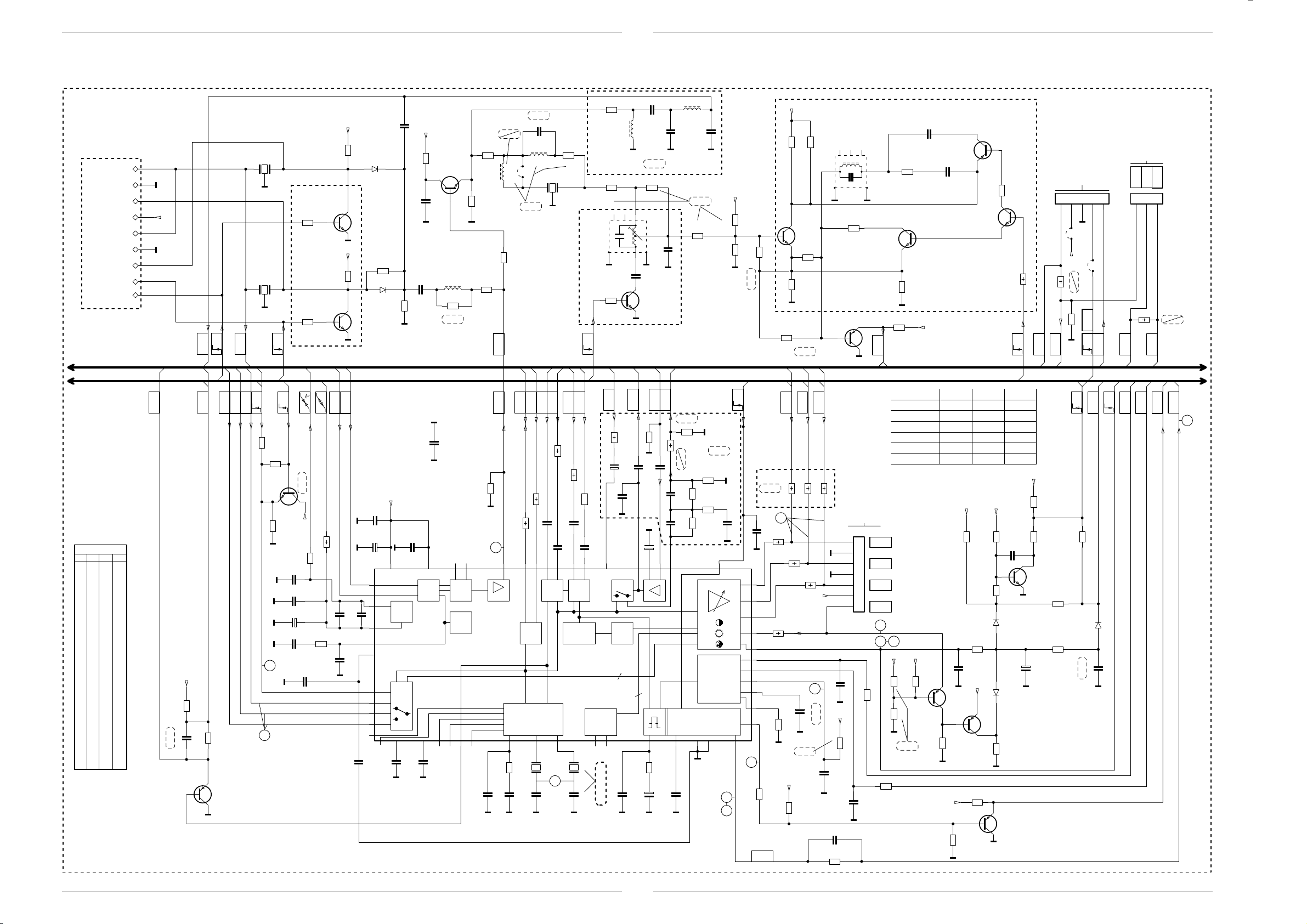
M 1000 / M 1001 Platinenabbildungen und Schaltpläne / Layout of the PCBs and Circuit Diagrams / Circuits imprimés et schémas électriques
M 1000 / M 1001 Platinenabbildungen und Schaltpläne / Layout of the PCBs and Circuit Diagrams / Circuits imprimés et schémas électriques
Teilschaltplan Video / Circuit Diagram Video Section / Schéma de la partie Vidéo
TON/FILTER-PLATTE
SOUND FILTER PANEL
SEITE / PAGE 3-20
SEITE / PAGE 3-17
IC34015
PIN V PIN V
1 1,3 29 2,5
2 4,0 30 2,5
3 3,8 31 2,2
4 3,8 32 0,3
5 2,9 33 0,3
6 3,3 34 2,5
7 4,9 35 2,5
8 4,8 36 5,0
9 6,8 37 8,1
10 0 38 3,0
11 3,5 39 5,1
12 8,1 40 2,0
13 3,5 41 1,3
14 0 42 3,6
15 3,4 43 3,9
16 0 44 0
17 3,5 45 0
18 4,9 46 4,0
19 2,7 47 4,0
20 2,8 48 2,9
21 2,1 49 4,6
22 2,4 50 4,6
23 3,7 51 3,8
24 3,7 52 3,9
25 3,7 53 4,0
26 0,2 54 4,1
27 0 55 3,0
28 2,9 56 4,1
+E
AFC
CR32167
+E
CR32162
ZF.
22k
CC33022
CC33016
M
*
M
4,7k
M
ZF_
*
CC33021
1n
CC33015
CD32167
CC34022
M
M
470u/10V
*
CR32160
CD32162
10n
C34021
48
49
54
*
53
5
9
26
23
24
25
27
47n
*
*
+
F32167
9
8
M
7
6
+E
5
4
M
*
M
OPTION C
CR32168
22k
CT32165
BC848B
3
2
F32162
*
1
1n
10n
0,1u
CC33017
CR32161
22k
U
n.V.
+E
CBR30
+
0,1u
CT32160
BC848B
U
R33019
0
CR33014
390
FBAS
AV2_OUT
n.v.
+E
560
CC34032
CT34031
BC858B
INTER-
CARRIER
FBAS
TEXT
CR34031
330p
CR34032
NORM3
U
390
AUDIO
GBR
ZF-MONO
U
M
RGB
330
CR34076
CR34077
2,7k
CR34078
18
17
NORM4
U
CT34075
BC848B
1,8k
M
M
M
M
2,2u/100V
M
OSD
DATA
U
CC33018
CC33020
C33019
CC33014
M
M
*
+E
CC32151
47
CR32106
0,1u
CC32106
M
CC32152
*
*
CR32163
M
M
CC34001
M
+E
CC34027
M
10n
37
AGC
TDA8842N2 MULTI/FR
RGB
39 38
16
0,1u
CC34039
CC34037
M
M
INL
CR32108
CT32105
BC817-25
270
CR32102
220
2,7u
L32108
M
470
CR32103
L32151
CR32111
*
CR32151
n.V.
**
0
BB
BB
0,1u
2,7k
CR34064
M
21
43 215655
OSC.ZF
AFC
VIDEO
IC34015
TDA8840N2
CR34042
3,3n
CC34041
CC34042
PAL/NTSC-DECODER MATRIX H-DRIVE
36 35 3433 32 31302928
CC32111
BR32108
INL
SDA
R34054
I C
82k
0,1u
n.V.
22p
L32109
10u
12u
F32109
SCL
R34055
100
CC34061
876
2
Q34043
CC34043
MMM
FBAS
100
CR32110
47
10
*
M
FBAS
IN_2
FBAS
IN_1
47
R44011
R34063
0,1u
CC34064
0,1u
CC34062
17
1312 11 10
FBAS Y/C
DELAY
PEAKING
Q34044
4,43MHz
22
18p
CC34044
CR32023
CR32109
F32101
8141-112-405
71
OPTION F
CR32119
4,7k
NORM5
U
CHROMA
470
470
CR34066
0,1u
0,1u
CC34067
3,58MHz
18p
NTSC/3,58MHz
M
180
2,2n/2,5%
1u
L32023
22
0
6
34
M
CC32118
M
1
AUDIO
AUDIO
EURO-AV
56k
R34071
+
C34071
22u/50V
CC34073
3,3n
CC34072
M
AUDIO
BLACK
STRE.
3
3
1n
CC52246
M M
C32023
F
STEREO
CR32105
0
2
8
M
33p
CT32119
BC848B
CR34071
1u
M
+
C34063
CR52247
+
C52247
C32024
CC32110
AUDIO
ZF-MONO
680
M
CC34069
CC34079
CC34080
47u/16V
18k
1u/100V
M
F
AUDIO
R34073
1n
CC52248
L32026
10u
/2,5%
*
CR32101
22p
M M
n.V.
CR34074
4,7k
1
680
330
INL.
CC32026
M
MM M
MONO
47p
8,2k
CR32104
CR32107
+E
SAT
CR34072
4,7k
2,2k
CR34080
2,2k
2,2k
RGB-MATRIX
V-DRIVE
4443 42 41
14
M
CC34075
M
50
39n
CR34079
39n
CR34075
15
M
10n
19
20
SCUTZ
U
68n
3,3k
1k
CBR32111
INL
CC57003
21
20
19
18
22
46
47
51
45
52
40
28
CR52261
SSC
n.V.
M
0
100p
R34059
R34056
1,8k
330
CR32142
100
CR52252
+E
CR32112
CT32111
BC848B
CR32141
CR32114
M
1,8k
0
R
OSDGOSDBOSD
xx
R34051
23
R34058
100
+
C52253
39k/2%
M
M
n.v.
+E
8,2k
CR52251
560
CR32150
1,8k
470
INL
R34052
R34057
100
470
8141-111-360
CT32124
BC858B
xx
xx
R34053
VERS C.I. TUBE CATHOD
A LA PLACA-ZOCALO TRC
M
M
+E
1n
27
+E
Mono
4,7u/100V
CR52254
F
C52254
0,1u/5%
M
CC52266
10p
CR52266
15k
OPTION G
F32121
6
24
31
7
8
MM
CR32143
820
FBAS
M
ZUR BILDROHRPLATTE
TO CART BASE
ALLA PIASTRA CINESC.
SEITE / PAGE 3-25
ST-RGB
1
R
2
3
G
4
5
B
6
7
SW
24
CC50011
100
M
CR50011
XX
CR50012
100
1n
CC50012
M
CR32124
33
CT32123
CR32113
M
CR32128
1k
**
37cm ORION
37cm PHI
45cm
51cm
55cm PHI
55cm SAMS
2625
+E
XX
CR57024
XX
CR57023
M
n.v.
CC32121
BC848B
470
+F
CR57025
CT57021
BC858B
120p
CC32124
120p
+E
CR57011
4,3k/2% 4,3k/2%
4,3k/2%
4,3k/2%
3,9k/2%3,9k/2%
3,9k/2%
3,3k/2%3,3k/2%
3,3k/2%
3,3k/2% 1k
+E +E
CR57012
CR57017
10k
5,6n
CC57021
0
CR57022
CT57020
**
M
+E
CR52262
M
BC858B
10k
M
+F
CR52264
1k
3k/2%
**
CT32122
BC858B
CR32133
CR57004
CR57008
D57011
D57023
CR57021
M
M
10k
CT32132
BC848B
100k
R32132
LAUF
FBAS
U
CR57022CR57012
1,3k
1,3k
1,2k
1k
1k
+E
CR57002
1M
CC57004
220k
1N4148
1N4148
680
CT52260
BC858B
39k
CR57003
22n
CT57005
BC848B
M
+
C57016
10u/50V
M M
ZUM SAT-BAUSTEIN
TO SAT.-MODULE
VERS MOD. SAT.
SEITE / PAGE 3-36
54321
R44014
FBAS
IN_2
CINCH
100k
CR57011
*
CR57016
22k
* oder OPTION – siehe Seite 3-23
* or OPTION – see page 3-23
* ou EN OPTION – voir page 3-23
ZUM SAT-BAUSTEIN
TO SAT.-MODULE
VERS MOD. SAT.
AL MOD. SAT.
AL MOD. SAT.
SEITE / PAGE 3-36
AL MOD. SAT.
AL MOD. SAT.
V
BR80303
+E
BR117
1
SAT
75
ENA
CR44012
M
EURO-
U
SCUTZ
U
CR57001
n.v.
SAT
AV_2
FBAS
SB
1M
D57013
CC57016
AV2_OUT
1N4148
ST-V3
VG
SCHUTZ
U
xx
FBAS
AV1_OUT
VA
IN_2
FBAS
FBAS
321
1
R44013
VB
FBAS
AV1_OUT
ST-V4
SAT
FBAS
SEITE / PAGE 3-23
SEITE / PAGE 3-15
H
HDR
SYNC
10
LOEWE.-Service
3 - 21
LOEWE.-Service
3 - 22
Page 40

Platinenabbildungen und Schaltpläne / Layout of the PCBs and Circuit Diagrams / Circuits imprimés et schémas électriques M 1000 / M 1001
Teilschaltplan Audio / Circuit Diagram Audio / Schéma de la partie Audio
Platinenabbildungen und Schaltpläne / Layout of the PCBs and Circuit Diagrams /Circuits imprimés et schémas électriques M 1000 / M 1001
*
INLAND INLAND
MONO
FR FR
MONO
NICAM
STEREO
TPS5,5 TPS5,5 TPS5,5TPS5,5TPS6,0 TPS6,0TPS6,0 TPS6,0TPS6,0 TPS6,0F32109
560 560 560 560 560CR32111
CC32151
22p
CC32152 47p47p47p
22p
27u 27u 27u 27u 27uL32151
0 OHMCR32160
CD32162
F32162
CR32163 680 680 680
4,7k4,7kCR32167
CD32167
F32167
F32410
8141- 8141- 8141- 8141- 8141- 8141-8140- 8140- 8140- 8140-
531-351
107-600107-600 107-600107-600 107-600 107-600
CD32411
CR32412
CR32420
F32420
CD32421
F32430
CR32451
CR32452
CR32453
CT32455
0 OHM 0 OHM
0 OHM 0 OHM 0 OHM 0 OHM
L9460 L9460 L9460
BA592BA592 BA592 BA592 BA592
K9554 K9554
22k
22k22k
22k 22k 22k 22k
BC848 BC848 BC848 BC848
CR32457
CT32460
CR32463
CD32465
CR32467
CR32468
CT32470
BC848
CR32471
CR32472
10k 10k 10k10k 10k
CR32473
CD32475
CT32475
CR32476
0 OHM 0 OHM0 OHM 0 OHM
BC848BC848 BC848
2,2k2,2k 2,2k 2,2k 2,2k
CT32480
CR32481
22k22k
22k 22k 22kCR32482
CR32483
10k 10k 10k 10k
CR32486
U4467 U4488IC32490
U4467 U4488
CC32492
BR32492
CC32493
F32493
C32494
CR32494
CR32527/CR32528
CC33021
1u
1u 1u1u
CC33022
0,22u 0,22u 0,22u0,22u 0,22u 0,22uCC34039
0 OHMCR43017
CR81010
0 OHM0 OHM
OPTION A
OPTION B
OPTION C
XX
OPTION D
OPTION F/G
OPTION H1/H2
OPTION I
XX X
OPTION J
OPTION K
OIRT
MONO
MULTI/7MULTI/7
MULTI/VI
MULTI/8 MULTI/8
MONOMONO
MONOSTEREO
STEREOSTEREO
000000CBR101
2,2n2,2n1,5n2,2nC32024
0 OHM
BA592BA592
SFE5,5SFE5,5SFE5,5
0 OHM0 OHM 0 OHM
BA592BA592
0 OHM 0 OHM 0 OHM
SFE6,5SFE6,0
531-351531-351531-351
BA592BA592BA592 BA592 BA592BA592 BA592 BA592
1n1n 1n1n1n1n 1n 1nCC32412
1k1k1k 1k 1k
G6255
470 470
G6255K3452 G6259 K3451K3451K3451K3451 G1984G1962F32412
1k
L9420
0 OHM0 OHM0 OHM
22k 22k
22k22k
BC848
BC848
22k 22k
BA592 BA592
0 OHM 0 OHM
BC848
22k22k
22k 22k
BA592 BA592
BC848
22k22k22k
0 OHM0 OHM0 OHM
BC848BC848
4,7k 4,7k 4,7k
BC848BC848 BC848BC848BC848BC848 BC848 BC848
22k22k
22k 22k22k
2,2k2,2k2,2k 2,2k 2,2k2,2k 2,2k 2,2k
1n1n
XX
6,8p 6,8p
1u 1u
TDA8841?TDA8841TDA8842 TDA8842 TDA8842 TDA8842TDA8840TDA8842TDA8840IC34015
0 OHM 0 OHM 0 OHM0 OHM0 OHM0 OHM
0 OHM
0 OHM 0 OHM 0 OHM 0 OHM
X
0 OHM0 OHM0 OHM0 OHM
-709-709
0,47u0,47u
150150
XXXXXXX
XX
XX
X
XXXXXX
X
XXXX
X
X
XX
VIDEO
TUNER
SEITE / PAGE 3-18
SEITE / PAGE 3-14
VIDEO
TUNER
PROZESSOR
TUNER
VIDEO
TUNER
VIDEO
PROZESSOR/TUNER
ST-ASIS4
TUNER
SAT-NACHRUESTUNG
RETROFITTING SAT
MONO
MONO SAT
STEREO
STEREO SAT
CR40011
2,2k
CC40012
+
C40021
CR40015
47u/16V
A A
D40022
1N4148
D40012
1N4148
BY
STAND
RESET
U
U
1N4148
D40064
STEREO
CR40065
2,2k
ASIS
CR40075
1
2
R44014
R44013
11
-1
-
470p
M
CR40016
1k
10k
NF
NF
MUTE
MUTE2
U
U
+F
22k
CR40064
CT40065
BC848B
A
CR40063
+
C40062
A A
1N4148
D40065
R43001
R43019
-
-
+M
CR40019
CR40023
1K
CR40060
100
10k
1u/100V
CT40015
BC858B
5,6k
10k
A
AUDIO
MONO
CC40011
CR40026
CC40071
D40061
D40062
CR40068
MONO1/2W
+E
CC40023
NF-L
0,22u
2,2k
3,3n
A
D40060
1N4148
CR40061
10k
1N4148
1N4148
ZPD7,5
D40063
1k
A
CR40022
0,1u
A
SEITE / PAGE 3-22
+M
NF-R
2,2k
R40072
**
CC40072
+
C40061
100u/25V
+M
M 1000
M 1001
n.V.
CC40099
C40001
A
+
470u/16V
4
3
MUTE
+
C40022
A
CR40052
**
!
SI40051
T1,6A
STEREO
0,1u
0,1u
A
5678
47u/16V
BR40054
R40054
4
5
Vref
12
11
7
6
10
n.v.
22
CT40025
BC807-40
A
A
CC40063
CC40062
MM
xx
A A
+M1
IC40001
TDA7267
**
0,1u
CC40098
CC40002
A
0,1u
1
C40031
2
+
470u/10V
A
CC40032
CR40032
R40053
2,2
R40051
1,8/4W
3
+
-
+
-
+
-
+
-
STANDBY
MUTE
TDA7266M_MONO
TDA7297_STEREO
89
A
STEREO
MONO 4/8W
0,1u
CR41018
4,7
A
A
MONO
CC40056
0,1u
C40057
+
**
13
IC40050
A
+M1
/16V
R
L
R
L
100n
V2BK001
10111
**
CR41014
10111
CC41116
STEREOMONO 4/8WMONO 1/2W MONO 1/2W
KH1BUCHSE KH1BUCHSE KH1
OHNE BUCHSEBUCHSE KH2BUCHSE KH2
0
1
3,3n0,1u 0,1u0,1u
00
KH1
**
**
CC41012
KH2
V2BK003
**
A
AA
CR41116
CR41017
A
**
CR41016
CC41113
5,6n
A
**
L41011
L41111
CR41011
CR41014
CC41012
CC41112
CR41017
CR41116
CR41016
CR40052
BR40054
R40054
C40057
-014-014
0
0
5,6n
5,6n
5,6n
47
47
00
1000u 1000u 1000u2200u
0
0
0 470
11 1
MONO 4/8W MONO 4/8W
-014-014
5,6n
11
CC40072
L41011
CR41009
KH-L
00CR40076
-014
**
CC41011
A
33
SEITE / PAGE 3-20
5,6n
CC41014
A
3
2
5,6n
CR40077
CR40078
CC41116
220
ST-H
3
2
1
KH-L
A
KH-R
33
CR41008
KH-R
8,2n
CC41009
CR41011
STEREO
**
CR40079
0
MONO
A
3
2
**
CC41013
V
**
CR40076
A
A
ST-LS-L
2
1
ST-LS
1
2
3
MONO
ST-LS-R
2
1
**
L41111
CC41112
**
A
CR40078
**
CC40038
22n
STEREO
CC40049
22n
301098
CR40077
**
A
A
1
MP304
CR40038
2
4,7
15
STEREO
CR40049
14
4,7
3 - 23
LOEWE.-Service
3 - 24
LOEWE.-Service
Page 41

M 1000 / M 1001 Platinenabbildungen und Schaltpläne / Layout of the PCBs and Circuit Diagrams / Circuits imprimés et schémas électriques
29304-722.65/2L(03)
5
0123456789
BR739
3
4
5
6
7
8
9
R773
R779
R759
R739
C717
BR740
71
ST-RGB
R751
R771
R753
R733
51
ST-BR
R760
C716
R717
BR771
BR751
BE
T756
BE
T736
C731
BE
T741
BE
T781
BE
T776
BE
T761
D817
CE
T815
R715
BR779
R718
4
5
6
7
8
910
11
12
C781C814
C818
D819
C817
29304-722.65/4B(03)
UG2
AQUA.
3
2
1
24
4
5
6
29304-722.65/2L(03)
5
0123456789
CC742
CC754
CC734
CC783
CC762
CC774
CR817
CR816
CR771
CR754
CR732
CR731
CR782
CR734
CR752
CR783
CR776
CR819
CR763
CR762
CR761
CR736
CR735
CR741
CR777
CR751
CR737
CR774
CR781
CR764
CR742
CR757
CR756
CR744
CR772
CR784
CR813
CD742
CD781
CD762
CD811
CBR743
CBR744
CBR742
CBR741
CC763
CD734
CC743
CR814
CC782
CT810
29304-722.65/4LS(03)
0V
0V
0V
11223
3
2V/cm, 10µs/cm
M 1000 / M 1001 Platinenabbildungen und Schaltpläne / Layout of the PCBs and Circuit Diagrams / Circuits imprimés et schémas électriques
Bildrohrplatte / CRT Panel / C.I. Tube
VARIANTESIGNAL
BRUECKEN:
29305-022.20 14" MINI NECK
BILDROHRPLATTE
CR734
CD734
LOEWE.-Service
immer
nur bei MINI NECK
nur bei MINI NECK
wenn CR761 oder CR763CBR744
M immer
+2
+2
BR/5
BR/7
8
J
BR779
BR739
BR740
CBR741/742/743
-022.18 15"...21" MINI NECK
-022.19 15"...21" SMALL NECK
M
*
*
+
CR819
CR816
PLACA ZOCALO TRC
PIASTRA CINESC.
C.I. TUBE CATHOD.
+1
1k
CR736
270p
CC734
R
LS4148
2
*
R733
+1
*
1k
C817
CR817
BAV21
D819
100u/25V
+
M
C814
1N4148
CD811
2,7k
CR814
CR813
T736
1,5k
R739
BF421
+2
CR741
+2
*
+2
*
T741
CC742
3,9k
CR732
220
CR731
L520
V
H
J
J
142
3
567
ZUM CHASSIS
AL CHASIS
SEITE / PAGE 3-16
AL TELAIO
VERS CHASSIS
TO CHASSIS
SMALL NECK
4,7n
C818
BAV21
D817
MINI NECK
1k
R718
MM
*
T815
PBF259
M
CT810
BC858B
*
M
10k
CC743
39p
CR754
CD742
330
MM
CR742
22
CR744
0
90
SMALL-/MINI-
ST-SN
8
(9)
(7)
64
5
*
*
R759
R760
CC754
2
R753
+1
270p
*
CR756
G
1
ST-RGB
1k
RUFG
1k
LS4148
NECK
9
11
(5)
(3)
T756
BF421
*
T761
BR751
220
CR751
2
M
7
6
ZUM CHASSIS
TO CHASSIS
567
10
(4)
(6)
+2
*
CR761
390p
CC762
CC763
3,9k
M
CR752
(8V)
+2
3
M
B
+E
AL TELAIO
AL CHASIS
SEITE / PAGE 3-22
VERS CHASSIS
12345
SW
(8)
1,5k
R717
*
24
12
(11)
C717
330
CR762
22
CR764
4,7n
MM
CR777
1
4
13
(-)
(1)
(10)
1k
CR7741kCR776
CC774
CD762
LS4148
2
R773
+1
470
10u/50V
CD781
LS4148
+
C781
+2
1,5k
R779
330p
B
*
*
T781
BR771
M
ONLY IF REQUIRED
NUR VORGESEHEN**
ST2
+2
T776
BF421
*
CR781
330
MM
CR782
*
CC782
22
CR784
3,9k
M
CR772
220
CR771
+
C731
M
ST-BR
(130V) 14"
(200V) 15"..20"
+1
4,7u/250V
+C
SOLAM. PREVISTO PARA
SOLO PREVISTO
PREVU
ZUM CHASSIS
1
1
AL CHASIS
SEITE / PAGE 3-16
AL TELAIO
VERS CHASSIS
TO CHASSIS
12345
230698
ST1
CRT PANEL
UG2
ZUM ZEILENTRAFO
CC763
470p390p
CC782CC742
CR817C817CR816 CR819
470k 1u/100V 560k
R760
1,5k
R759
4,7k
CR781
CR761
CR741
T781
T761
T741
BF422
10k
R783
R753
R733
BV0411
*
-022.20
14" MINI NECK
HS
AL TRASF. DI RETE
AL TRANSF. DE LINEAS
SEITE / PAGE 3-16
VERS TRANSF. ALIMENT
TO LINE TRANSFORMER
39p560p470p
470p 560p 39p
220k
220k
4,7M
4,7M
1u/250V
1u/250V
220k
220k
1,5k
1,5k
BF871
BF871
12k
12k
BV0617
BV0617
-022.18
-022.19
15"-21" MINI NECK
15"-21" SMALL NECK
3 - 25
Bestückungsseite, Ansicht von oben / Component Side, Top View / Côte composants, Vue de dessus
4
0V
5
0V
0V
4
5 6 50V/cm, 10µs/cm
6
0V
24 2V/cm, 20µs/cm
Lötseite, Ansicht von unten / Solder Side, Bottom View / Côte soudures, Vue de dessous
LOEWE.-Service
3 - 26
Page 42
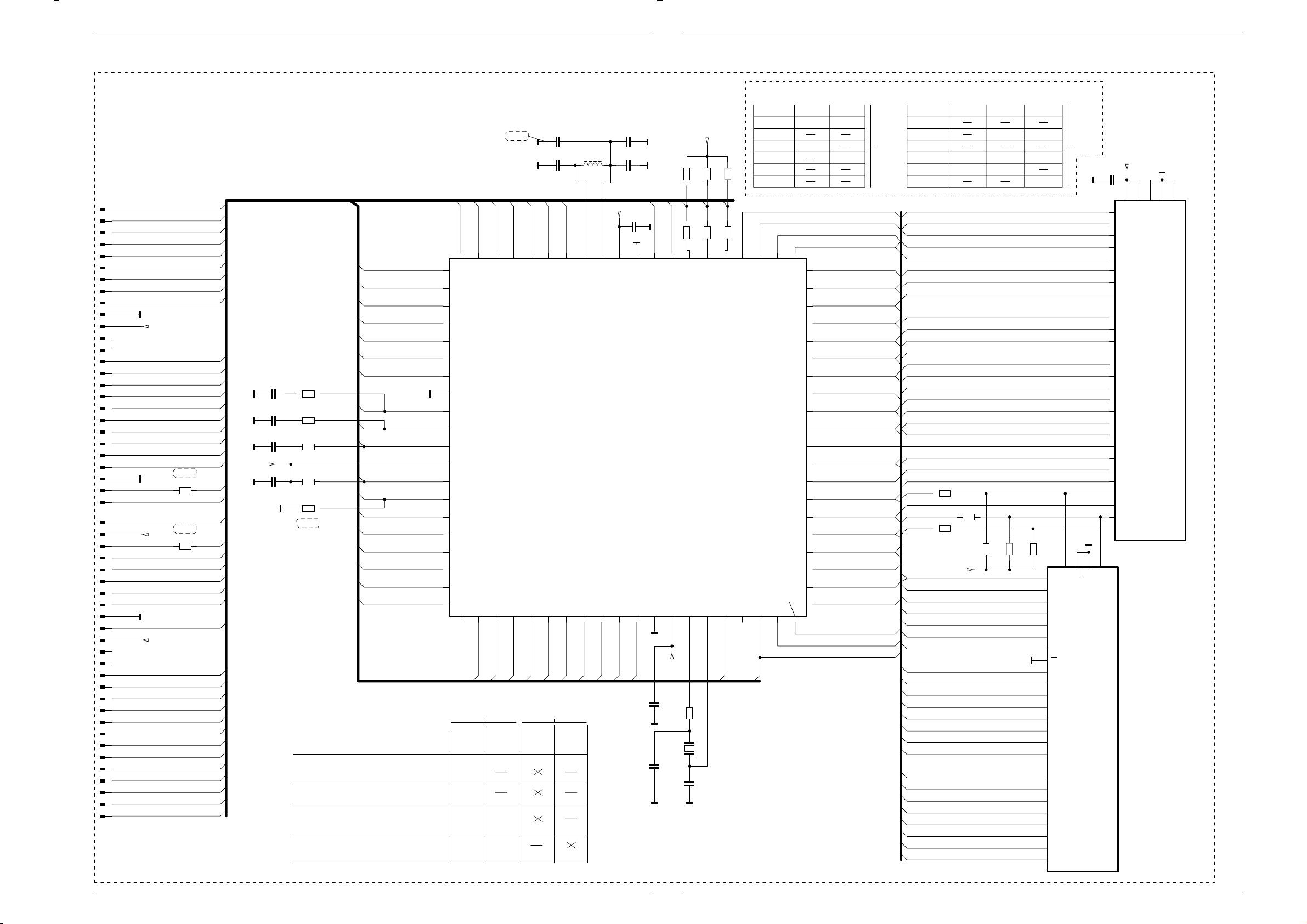
Platinenabbildungen und Schaltpläne / Layout of the PCBs and Circuit Diagrams / Circuits imprimés et schémas électriques M 1000 / M 1001
Prozessor-Platte / Processing Board / C.I. du processeur
Platinenabbildungen und Schaltpläne / Layout of the PCBs and Circuit Diagrams /Circuits imprimés et schémas électriques M 1000 / M 1001
SEITE / PAGE 3-17
PROZESSOR-PLATTE
PROCESSING BOARD
PLAQUE CALCULATEUR
PIASTRA CALCOLATORE
PLACA CALCOLADOR
VARIANTE 1.0
29305-119.37/.39/.40/.46/.47/.48/.54/.56/.57/.58/.59/.60
VARIANTE 2.0
29305-219.11/.12
STL1
STL1
STL1
STL1
STL1
STL1
STL1
STL1
10
STL1
11
STL1
12
STL1
13
STL1
14
STL1
15
STL1
16
STL1
17
STL1
18
STL1
19
STL1
20
STL1
21
STL1
22
STL1
23
STL1
24
STL1
25
STL1
26
STL1
STL1
STL2
STL2
STL2
STL2
STL2
STL2
STL2
STL2
STL2
10
STL2
11
12
STL2
13
STL2
ST2
14
STL2
15
STL2
16
STL2
17
STL2
18
STL2
19
STL2
20
STL2
21
STL2
22
STL2
23
STL2
24
STL2
25
STL2
26
STL2
.61/.63/.64/.65/.66/.70/.71/.72/.74/.75/.76
1
2
3
4
5
6
7
8
9
M
+5V
M
CR80918
1
2
+5V
3
4
5
6
7
8
9
M
CR80919
+5V
n.V.
n.V.
01
02
03
04
05
06
A17
15
23
25
0
26
27
29
0
30
31
32
33
34
36
40
41
42
43
44
45
46
47
48
52
VARIANTE 2.1
29305-219.01/.02/.03/.06/.07/.10
29305-319.01/.02/.05/.09
VARIANTE 2.2
29305-219.08/.09
29305-319.03/.04/.06./07/.08/.11/.13
CC80911
M
CC80912
M
CC80913
M
0,22u
33n
33n
CR80911
8,2k
CR80912
6,8k
CR80913
6,8k
+5V
CC80914
M
0,1u
CR80914
82k
CR80916
M
470k
n.V.
VARIANTE 1.0
29305-119.37/.39/.40/.46/.47/.48/.54/.56/.57/.58/.59/.60
.61/.63/.64/.65/.66/.70/.71/.72/.74/.75/.76
VARIANTE 2.0
29305-219.11/.12
VARIANTE 2.1
29305-219.01/.02/.03/.06/.07/.10
29305-319.01/.02/.05/.09
VARIANTE 2.2
29305-219.08/.09
29305-319.03/.04/.06./07/.08/.11/.13
vorgesehene Bestueckungsoptionen
*
CBR80921
P0-1
P1-7
P0-0
P1-6
CC80902
M
CC80901
M
100p/2%
XX
VS/P4-7
P1-5
45
HS/SC
P1-4
6,8u/2%
39
n.V.
07070808090946
06
05
P0-4
04
03
02
31
32
33
34
25
26
27
29
30
40
41
42
43
36
44
61
P0-5
P0-3
62
P0-6
63
P0-7
64
P2-3
65
P2-2
66
P2-1
67
P2-0
68
M
VSSA
69
FIL3
70
FIL1
71
FIL2
72
VDDA
73
IREF
74
CVBS
75
P3-7
76
P3-6
77
P3-5
78
P3-4
79
P3-3
80
P3-2
P0-2
P3-1
P3-0
12345678
CC80906
M
2,2p
CC80903
L80901
M
33p/2%
+5V
38
CC80904
0,1u
51515050494948
M
M
COR
VSS
VDD
LCIN
LCOUT
CIC80905
ICQF80
SDA5250
P1-0
P1-1
P1-2
P1-3
91011121314151617181920
VSS
**
CR80905
**
CR80906**CR80907
BL
BLAN
XTAL2
VDD
+5V
**
CR80909
GR
XTAL1
**
CR80910
47
**
CR80908
RT
RST
D3
ALE
CBR80922
CBR80923
CBR80924
CBR80925
CBR80926
D2
A17/P4-0
M
CC80915
M
CC80917
M
+5V
0,1u
56p
13
33
CR80917
Q80917
CC80918
M
12
18MHz
15p
15
A17
52
01
161617171818191920202121222223
RGB EPROM
**
CR80907
CR80908
CR80905CR80906
CR80909
CR80910
IC80920
IC80920
30PIN28PIN
M27C2001M27C512
0 OHM
470
560
560
4,7k
4,7k
0 OHM 0 OHM
0 OHM
4142434445464748495051525354555657585960
D1
D4
D5
D0
D6
A0
A0
D7
A1
A1
A2
A2
A10
A10
A3
A3
A4
A4
A11
A11
A5
A5
A9
A9
A6
A6
A8
A8
A7
A7
A13
A13
A12
A12
A14
A14
A15
A15
A18/P4-1
A16
0 OHM
D3
D2
D4
D1
40
D5
39
D0
38
D6
37
A0
36
D7
35
A1A1
34
A2
33
A10
32
A3
31
A4
30
A11
29
A5
28
A9
27
A6
26
A8
25
A7
24
A13
23
A12
22
A14
21
A15
A18
A16
A17
*
IC80920
CBR80921
CBR80922
CBR80923
CBR80924
CBR80925
CBR80926
D0
D1
D2
D3
D4
D5
D6
D7
A0
A1
A2
A3
A4
A5
A6
A7
A8
A9
A10
A11
A12
A13A13
A14A14
CBR80924
A15
A16
A17
CBR80926
A18
A14
A9
A10
A11
A12
A13
A8
D7
D6
D5
D4
D3
D2
D1
D0
A7
A6
A5
A4
A3
A2
A1
A0
*
*
CBR80922
*
+5V
0 OHM0 OHM
*
CBR80923
*
CBR80921
M27C4001M27C2001M27C1001M27C512M27C256IC80920
0 OHM0 OHM
0 OHM0 OHM0 OHM
0 OHM
*
CBR80925
27
24
21
23
2
26
25
22
M
19
18
17
16
15
13
12
11
3
4
5
6
7
8
9
10
A14
A9
A10
A11
A12
A13
A8
OE
D7
D6
D5
D4
D3
D2
D1
D0
A7
A6
A5
A4
A3
A2
A1
A0
A15
32 PIN28 PIN
M
M
2814201
CF
GND
*
**
IC80920
28 PIN
0,1u
CC80921
VCC
+5V
M
1
322422
16
*
**
IC80920
32 PIN
31 30 2 3 29 28 4 25 23 26 727 5 6 8 9 10 11 12 21 20 19 18 17 15 14 13
180698
3 - 27
LOEWE.-Service
3 - 28
LOEWE.-Service
Page 43

M 1000 / M 1001 Platinenabbildungen und Schaltpläne / Layout of the PCBs and Circuit Diagrams / Circuits imprimés et des schémas électriques
Prozessor-Platte / Processing Board / C.I. du processeur
Bestückungsseite / Component Side / Côte composants
(14)
IC80920
16
17 32
27
126
06
20
116
STL2
STL1
Q80917
CC80902
L80901
52
42
10
29304-792.37/4B(00)
1
126
29304-792.37/2L(03)
Bestückungsseite (SMD) / Component Side (SMD) / Côte composants (SMD)
0123456789
CBR80921
CBR80922
CR80919
CR80918
CBR80925
CBR80926
CC80918
CR80917
CBR80923
CC80921
CC80915
CBR80924
20 1
CIC80905
40
CR80908
CC80906
CC80904
CR80907
CC80903
60
CC80901
CR80909
CR80910
CC80917
CR80916
CR80914
CR80913
CR80912
CR80911
CR80905
29304-792.37/4BS(03)
29304-792.37/2B(04)
CC80914
CC80913
CC80912
CC80911
CR80906
LOEWE.-Service 3 - 29
Page 44

Platinenabbildungen und Schaltpläne / Layout of the PCBs and Circuit Diagrams / Circuits imprimés et des schémas électriques M 1000 / M 1001
SAT-Baustein / SAT Module / Module SAT
Bestückungsseite, Ansicht von oben / Component Side, Top View / Côte composants, Vue de dessus
D38047
C38057
MF38063
U-LNB
L38101
TUNER
L38161
C43032
ST-A2
D38046
13
41
C38033
58
IC38030
TR38050
456
D38051
C38051
L38032
L38056
C38054
C38008
C38034
C38076
C38222
L38008
C38101
C38124
L38144
L38156
C32364
Q32305
C32327
C43037
1 26
L32342
WEISS
L38077
111
IC32000
L32343
ST-V3
15
SCHWARZ
IC38220
1
FBAS
C38142
C38121
C32360
2752
15
ST-V3A
1120
12
10
C38193
C38197
C38192
SER2000
29304-362.28/4B (02)
F38183
Durchlaufrichtung
12
10
9
C40010
8
7
ST-A1
6
ST-V2
C38236
111
2
3
4
5
ST-V4
13
31
IC38110
C38171
C38001
L38001
C32322
C32324
ST-AV3
ROT
15
140
130
120
110
100
90
80
70
60
50
40
30
20
10
Koordinaten für die Bauteile der
Bestückungsseite (Oberseite)
Pos.-Nr./ Koordinaten/
Pos. No./ Coordinates/
Pos. N°/ Coordonnées
XY
AN10 118 170
AN11 0 170
AN12 118 0
AN13 0 0
AN14 10 85
AN15 108 156
C32322 17 25
C32324 20 16
C32327 72 47
C32360 68 41
C32364 105 51
C38001 17 51
C38008 90 93
C38033 68 125
C38034 81 118
C38051 100 114
Pos.-Nr./ Koordinaten/
Pos. No./ Coordinates/
Pos. N°/ Coordonnées
C38054 90 110
C38057 111 110
C38076 71 104
C38101 89 78
C38121 55 54
C38124 78 76
C38142 54 62
C38171 25 62
C38192 29 70
C38193 38 69
C38197 50 68
C38222 69 85
C38236 34 78
C40010 41 24
C43032 110 42
C43037 110 31
111
XY
Coordinates of the Components on
the Components Side (Top Side)
Pos.-Nr./ Koordinaten/
Pos. No./ Coordinates/
Pos. N°/ Coordonnées
XY
D38047 111 127
D38051 100 117
F38183 28 41
IC32000 78 26
IC38030 80 132
IC38110 14 69
IC38220 50 85
L32342 94 13
L32343 64 6
L38001 10 42
L38008 100 80
L38032 71 116
L38056 100 107
L38077 63 108
L38101 110 76
Pos.-Nr./ Koordinaten/
Pos. No./ Coordinates/
Pos. N°/ Coordonnées
L38144 72 53
L38156 90 51
L38161 112 52
MF38063 110 91
Q32305 99 41
STA01 31 7
STA02 91 7
STAV03 7 28
STV02 30 88
STV03 56 113
STV03A 42 99
STV04 21 78
XY
111
0
Y
0102030405060708090100110120
X
Coordonnées des composants côté
composants (Vue de dessus)
Pos.-Nr./ Koordinaten/
Pos. No./ Coordinates/
Pos. N°/ Coordonnées
XY
TR38050 98 126
TUNER 95 65
3 - 30 LOEWE.-Service
Page 45
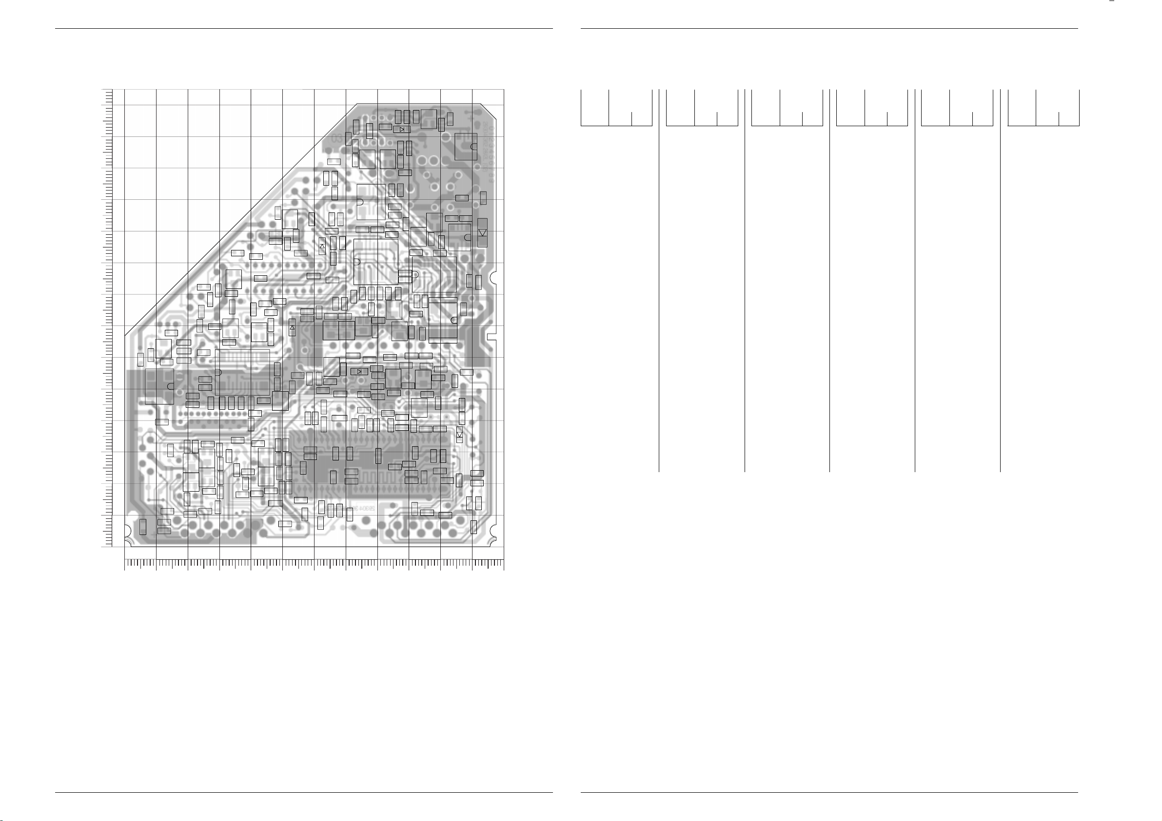
M 1000 / M 1001 Platinenabbildungen und Schaltpläne / Layout of the PCBs and Circuit Diagrams / Circuits imprimés et schémas électriques
CR38133
CR32342
CR32340
CR43012
CR32307
CR43036
CR43031
CR32314
CR32315
CR32309
CR32301
CR32303
CR32323
CR43001
CR43004
CR43017
CR32350
CR32355
CR32351
CR32352
CR32353
CR32354
CR43033
CR43032
CR38157
CR32327
CR32326
CR43021
CR43020
CR32336
CR32345
CR32322
CR38194
CR32321
CR39199
CR32319
CR32318
CR40046
CR32310
CR32317
CR32313
CR32311
CR40026
CR32302
CR32304
CR32324
CR38211
CR38036
CR38013
CR38011
CR38163
CR38012
CR38071
CR38181
CR38182
CR38034
CR38022
CR38062
CR38143
CR38162
CR38102
CR38023
CR38021
CR38016
CR38066
CR38189
CR38073
CR38074
CR38024
CR38151
CR38183
CR38184
CR38072
CR38177
CR38176
CR38126
CR38123
CR38122
CR38124
CR38186
CR38144
CR38187
CR38152
CR38153
CR38038
CR32367
CR38128
CR38161
CR38067
CR38041
CR38164
CR38061
CR38188
CR38207
CR38002
CR38001
CR38003
CR38127
CR38131
CR38202
CR38201
CR38223
CR38231
CR38232
CR38263
CR38132
CR38262
CR38261
CR38104
CR38103
CR38192
CR38193
CR38198CR38197
CR38076
CR38233
CR38129
CC32341
CC43012
CC43017
CC32334
CC32340
CC32342
CC43002
CC43007
CC43003
CC32306
CC32307
CC32309
CC32316
CC32365
CC32302
CC32328
CC32303
CC32347
CC32308
CC32314
CC32310
CC32315
CC32345
CC32366
CC32351
CC32352
CC32304
CC43021
CC32344
CC43020
CC32348
CC32311
CC32312
CC32317
CC32318
CC38111
CC43031
CC43006
CC43036
CC32313
CC32305
CC40022
CC40042
CC38207
CC38052
CC38154
CC38183
CC38146
CC38147
CC38091
CC39156
CC38075
CC38072
CC38172
CC38034
CC38102
CC38036
CC32367
CC38181
CC38063
CC38071
CC38177
CC38148
CC38178
CC38187
CC38077
CC38184
CC38186
CC38141
CC38122
CC38144
CC38157
CC38131
CC38066
CC38161
CC38037
CC38058
CC38173
CC38103
CC38206
CC38202
CC38211
CC30221
CC38224
CC38226
CC38198
CC38212
CC38264
CC38236
CC38124
CC43018
CC38223
CC43013
1
CIC38205
CT38196
CT32325
CT32308 CT32310
CT32312
CT32315
CT32320
CT38190
CT38185
CT38150
CT38130
CT38040
CT38195
CIC38045
1
CIC38175
CIC38060
CC32343
CC32333
CC32346
CD38061
CD32367
CD38201
CD38038
CD38188
CD38189
CT38160
CT38070
CT38015
CT38020
CT38125
CT38065
CT38140
CT38135
CT38010
CT38005
CT38260
CT38155
CT38261
CR38236
CR32359
CR38234
CR38042
CR38171
CR38063
CR38033
CR38121
CR38191
CR38196
CR40010
CR38226
CR38227
1
CIC38010
1
CIC38091
1
CIC38080
1
CIC38005
CR38224
CR38032
1
CIC38090
CR38019
CR38035
CR38015
CR38017
CC38038
CC38215
29304-362.28/4LS (02)
0
10
20
30
40
50
60
70
80
90
100
110
120
130
140
Y
0
10 20 30 40 50 60 70 80 90 100 110 120
X
M 1000 / M 1001 Platinenabbildungen und Schaltpläne / Layout of the PCBs and Circuit Diagrams / Circuits imprimés et schémas électriques
Lötseite, Ansicht von unten / Solder Side, Bottom View / Côte soudures, Vue de dessous
Koordinaten für die Bauteile der
Lötseite (Unterseite)
Pos.-Nr./ Koordinaten/
Pos. No./ Coordinates/
Pos. N°/ Coordonnées
XY
CC30221 44 77
CC32302 92 30
CC32303 95 37
CC32304 107 41
CC32305 83 42
CC32306 100 37
CC32307 27 18
CC32308 30 22
CC32309 62 8
CC32310 57 10
CC32311 26 33
CC32312 30 26
CC32313 42 33
CC32314 52 28
CC32315 52 23
CC32316 49 28
CC32317 46 18
CC32318 49 23
CC32328 71 30
CC32333 80 29
CC32334 100 24
CC32340 76 43
CC32341 86 25
CC32342 68 48
CC32343 63 39
CC32344 71 10
CC32345 66 22
CC32346 68 41
CC32347 67 30
CC32348 88 38
CC32351 72 24
CC32352 72 21
CC32365 88 41
CC32366 91 38
CC32367 106 21
CC38034 66 122
CC38036 83 133
CC38037 89 136
CC38038 92 136
CC38052 107 110
CC38058 114 110
CC38063 100 97
CC38066 86 105
CC38071 97 98
CC38072 84 113
CC38075 65 100
CC38077 68 104
CC38091 107 75
CC38102 94 68
Pos.-Nr./ Koordinaten/
Pos. No./ Coordinates/
Pos. N°/ Coordonnées
XY
CC38103 91 61
CC38111 15 68
CC38122 78 75
CC38124 69 77
CC38131 62 74
CC38141 58 53
CC38144 78 59
CC38146 63 49
CC38147 65 52
CC38148 84 60
CC38154 90 51
CC38157 85 49
CC38161 105 53
CC38172 25 62
CC38173 48 56
CC38177 31 46
CC38178 27 46
CC38181 24 70
CC38183 22 48
CC38184 37 46
CC38186 40 46
CC38187 44 46
CC38198 41 75
CC38202 86 80
CC38206 66 96
CC38207 80 100
CC38211 78 80
CC38212 69 96
CC38215 84 80
CC38222 49 78
CC38223 56 93
CC38224 36 93
CC38225 60 86
CC38226 67 112
CC38236 34 80
CC38264 52 96
CC39156 99 53
CC40022 42 17
CC40042 39 24
CC43002 101 29
CC43003 14 11
CC43006 13 8
CC43007 98 29
CC43012 76 48
CC43013 109 14
CC43017 80 51
CC43018 111 20
CC43020 110 6
Coordinates of the components on the
Solder Side (Bottom Side)
Pos.-Nr./ Koordinaten/
Pos. No./ Coordinates/
Pos. N°/ Coordonnées
XY
CC43021 112 14
CC43031 96 11
CC43036 101 10
CD32367 106 35
CD38038 88 132
CD38061 113 99
CD38188 74 56
CD38189 53 69
CD38201 63 95
CIC38005 11 51
CIC38010 98 86
CIC38045 108 127
CIC38060 106 98
CIC38080 78 109
CIC38090 101 72
CIC38091 101 72
CIC38175 37 55
CIC38205 80 90
CR32301 91 21
CR32302 84 38
CR32303 91 23
CR32304 107 45
CR32307 30 17
CR32309 51 7
CR32310 33 29
CR32311 30 31
CR32313 48 32
CR32314 51 32
CR32315 52 19
CR32317 50 19
CR32318 38 20
CR32319 36 34
CR32321 22 32
CR32322 30 13
CR32323 20 15
CR32324 25 11
CR32326 20 32
CR32327 15 30
CR32336 92 12
CR32340 73 38
CR32342 75 40
CR32345 68 11
CR32350 65 11
CR32351 62 13
CR32352 57 25
CR32353 56 15
CR32354 90 26
CR32355 95 22
Pos.-Nr./ Koordinaten/
Pos. No./ Coordinates/
Pos. N°/ Coordonnées
CR32359 63 44
CR32367 102 21
CR38001 12 40
CR38002 8 61
CR38003 13 58
CR38011 89 87
CR38012 73 123
CR38013 73 127
CR38015 89 84
CR38016 92 93
CR38017 93 78
CR38019 95 78
CR38021 89 118
CR38022 109 84
CR38023 87 122
CR38024 87 126
CR38032 6 6
CR38033 73 133
CR38034 71 129
CR38035 78 132
CR38036 86 136
CR38038 103 135
CR38041 100 134
CR38042 90 126
CR38061 108 104
CR38062 103 104
CR38063 112 84
CR38066 86 108
CR38067 85 102
CR38071 84 99
CR38072 89 102
CR38073 87 113
CR38074 65 104
CR38076 100 93
CR38102 95 61
CR38103 91 68
CR38104 92 74
CR38121 72 61
CR38122 80 72
CR38123 58 72
CR38124 73 79
CR38126 67 77
CR38127 58 74
CR38128 65 73
CR38129 79 68
CR38131 70 73
CR38132 25 82
CR38133 24 74
CR38143 62 53
XY
Coordonnées des composants
côté soudures (Vue de dessous)
Pos.-Nr./ Koordinaten/
Pos. No./ Coordinates/
Pos. N°/ Coordonnées
XY
CR38144 69 56
CR38151 100 56
CR38152 89 58
CR38153 96 57
CR38157 80 54
CR38161 108 55
CR38162 99 46
CR38163 96 48
CR38164 80 57
CR38171 19 59
CR38176 25 53
CR38177 25 51
CR38181 34 46
CR38182 55 54
CR38183 22 45
CR38184 40 39
CR38186 41 42
CR38187 48 52
CR38188 53 51
CR38189 66 91
CR38191 19 65
CR38192 33 65
CR38193 28 70
CR38194 66 84
CR38196 19 62
CR38197 46 66
CR38198 46 70
CR38201 48 97
CR38202 81 80
CR38207 75 100
CR38211 75 80
CR38223 48 99
CR38224 5 59
CR38226 67 117
CR38227 64 117
CR38231 42 92
CR38232 43 85
CR38233 30 81
CR38234 27 78
CR38236 34 76
CR38261 48 106
CR38262 54 98
CR38263 59 104
CR39199 46 74
CR40010 48 14
CR40026 37 16
CR40046 35 24
CR43001 21 10
Pos.-Nr./ Koordinaten/
Pos. No./ Coordinates/
Pos. N°/ Coordonnées
CR43004 13 5
CR43012 78 38
CR43017 80 38
CR43020 80 48
CR43021 111 23
CR43031 58 41
CR43032 59 31
CR43033 59 28
CR43036 60 41
CT32308 26 22
CT32310 26 28
CT32312 45 28
CT32315 45 22
CT32320 21 27
CT32325 21 20
CT38005 12 63
CT38010 77 123
CT38015 85 75
CT38020 83 123
CT38040 96 135
CT38065 98 103
CT38070 93 98
CT38125 76 70
CT38130 65 69
CT38135 70 69
CT38140 65 57
CT38150 94 53
CT38155 85 53
CT38160 93 44
CT38185 49 46
CT38190 33 69
CT38195 43 68
CT38196 87 68
CT38260 52 104
CT38261 35 85
OM01 9 4
OM02 109 135
OM40 9 8
OM41 107 134
XY
LOEWE.-Service
3 - 31
LOEWE.-Service
3 - 32
Page 46
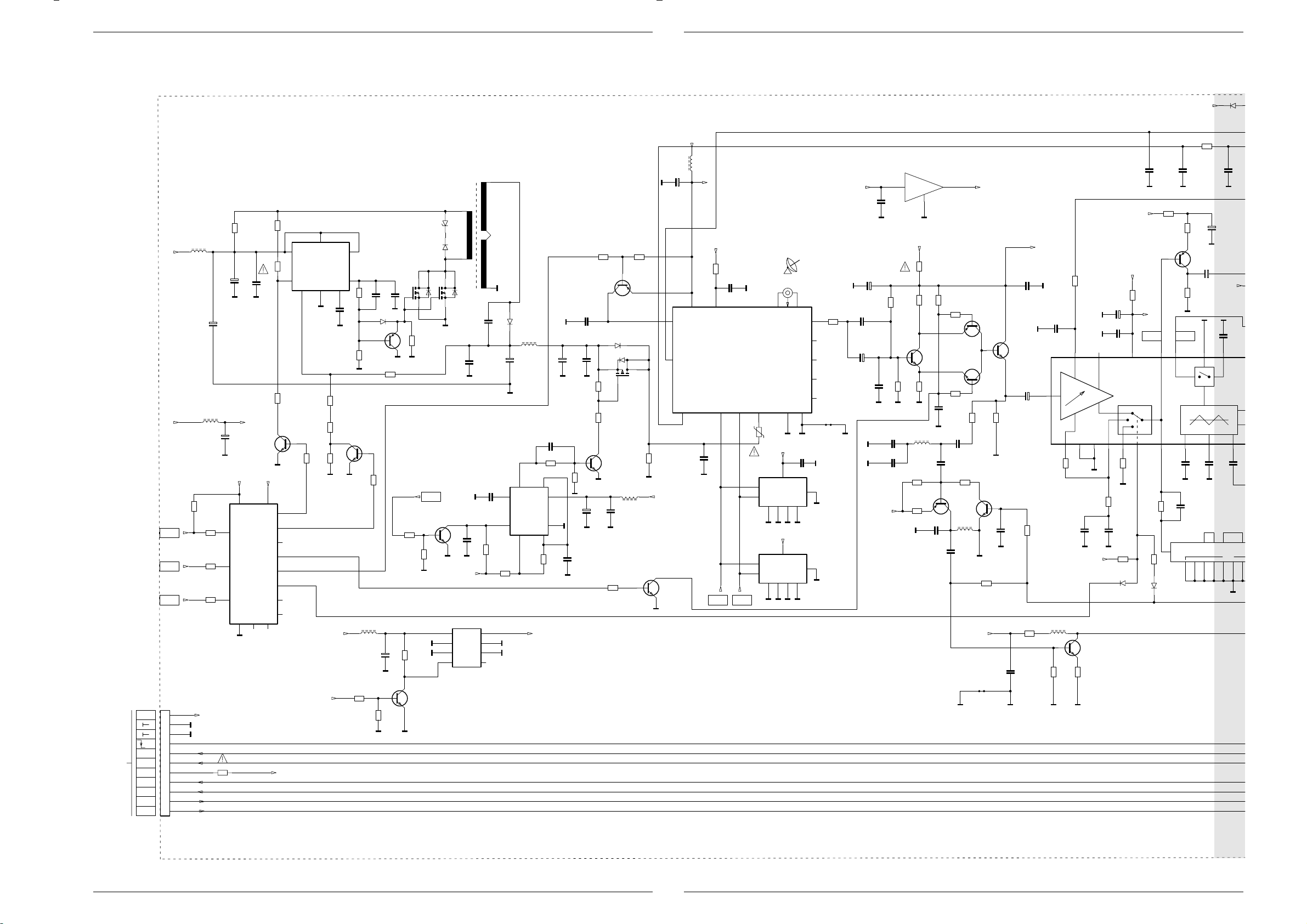
Platinenabbildungen und Schaltpläne / Layout of the PCBs and Circuit Diagrams / Circuits imprimés et schémas électriques M 1000 / M 1001
CR38202
SAT-Baustein / SAT Module / Module SAT
SAT-BAUSTEIN 29504-106.28
SAT. MODULE
MOD. SAT.
MOD. SATELITTE
SAT. MODULE
6
TR38050
1
AL CHASIS
TO CHASSIS
ZUM CHASSIS
VERS CHASSIS
ALLO CHASSIS
+33V
U
RESET
AUDIO-L
AUDIO-R
+M
SEITE / PAGE 3-19
KH-R
KH-L
AUDIO-R
CINCH
AUDIO-L
CINCH
0,11
C38034
L38008
47u
CR38033
+
C38033
470u/35V
CC38034
+
47u/40V
+5V/3
+
C38008
100u/10v
M1
L38032
+M
47u
+F
+5V/3 +5V/3
1
2
3
STROBE
DATA
CLOCK
16 15
CIC38010
HEF4094
HEF4094
10k
CR38011
ENA
SDA
SCL SDA SCL
10k
CR38015
10k
CR38017
10k
CR38019
M1
100
CR38034
6
100
CR38035
7
0,1u
M1M1
4,7k
CR38013
CT38010
BC848B
M1
14
LNB/OFF
Q5
7
14/18V
Q4
6
Q3
13
POL
Q6
5
CS_TUNER
Q2
4
Q1
12
Q7
11
Q8
1098
8
1
IC38030
MC34063
2
543
M1
4,7k
CR38012
CC38036
47/1%
CR38023
CR38021
+M
220p
M1
CR38024
820/1%
390
M1M1
CR38036
CR38038
M1
CT38020
BC848B
100
390
L38001
47uH
CC38037
CD38038
LS4148
BC858B
CT38040
4,7k
1n
CR38042
13k/1%
CR38022
+
C38001
CC38038
M1
CR38071
CR38001
100u/25V
CIC38045
Si9955/1
100p
10k
V
CT38005
BC848B
CR38002
ST-A1
+F
+33V
11
V
10
V
9
8
(NF-L)
7
(NF-R)
6
5
4
3
2
1
CR38032
0,11/SI
+M
10k
10k
CR38003
VV
ZPY16
D38046
BYT54M
D38047
CIC38045
Si9955/2
M1
10k
CR38041
M1M1
DISEQC
.
CT38070
BC548B
100k
CR38076
M1
8765
VV
VV
10k
3
CC38052
M1
xx
CC38071
M1M1
+F
KF120
CIC38005
5
W2TR067
4
M1
K
C38051
100p/1kV
0,1u
10n
CC38072
10k
CR38072
2,2k/1%
CR38073
4321
D38051
+
C38054
M1
5
4
BYV27-200
L38056
100u
470u/35V
3
NE555
CIC38080
7
6
2
+12V
CC38066
0,1u
4,7k
CR38066
20k/2%
M1
+
C38057
M1
8
M1
1
CR38074
M1
470u/35V
CR38067
CC38075
CC38103
1n
CC38058
M1M1
4,7k
M1
+
C38076
1,5n/2%
CR38103
10k
100n
2,2k
4,7k
CT38065
M1
100u/25V
CR38016
CT38196
CD38061
BYG22B
CR38061
CR38062
BC848B
CC38077
M1M1
4,7k
BC858B
CIC38060
SI4947
47u
L38077
0,1u
CR38104
4,7k
CT38015
2,2k
CR38063
M1
M1
Platinenabbildungen und Schaltpläne / Layout of the PCBs and Circuit Diagrams /Circuits imprimés et schémas électriques M 1000 / M 1001
+F
M1
C38101
1000u/6,3V
7
2
+F
BC848B
47u
L38101
+
+12V
CC38111
0,1U
VV
+5V/2
+33V
470
CR38102
CC38102
M1
0,1u
4
8
A
CR38129
3
5
TUNER
8
M1
M1M1
CC38091
0,1u
TEST
4321
M1M1
6
14
15
connection
7
M1
Net-
M1
29504-201.92
1
91011 1213
MF38063
0,1u
CC38063
M1
5
SDA
6
SCL
+5V/3
RXE040/400mA
VCC
CIC38090
M24C64MW6
A0 A1 A2 VSS
M1
C38121
+
V
220u/10V
0,1u
C38124
+
V
V
CC38124
V
CC38146
CC38147
CR38122
CT38125
5,6p
CR38124
22p
22p
CC38122
1k
100u/25V
V
+5V/1
+5V/3
8
VCC
5
SDA
6
SCL
A0 A1 A2 VSS
CIC38091
7
TEST
XX
M1
4321
M1M1M1M1
3
15k
BC848B
13k
+5V/2
CR38121
CR38123
CR38126
VV
L38144
27u
CR38151
4,7k
CR38153
100
V
IC38110
78L09
2
4,7/SI
560
CR38127
560
0,1u
CC38148
47p
CC38154
V
1
4,7k
CR38128
10k
CR38131
10k
CC38131
CC38144
15p
10p
CR38152
CT38150
BF550
CC39156
CT38135
BC848B
10k
L38156
15u
1n
V
CT38130
1,2k
CR38144
V
CR38164
+5V/1
Net-
connection
+9V
BC858B
CT38155
BC848B
15k
CR38143
V
CC38157
V
CT38140
BC848B
1k
0,1u
CC38161
CC38141
0,1u
C38142
22u/50V
CR38157
CR38161
0,1u
A
xx
CC38215
+12V
+5V/1
V
V
C38171
220u/16V
0,1u
CC38172
+
+12V
CR38171
3,3
+12V/1
V
CC38181
V
0,1u
1k
CR38189
19 18
CC38211
M1
M1 M1
CR38191
3,3
CR38192
CT38190
BC858B
CR38193
BB FBAS
1615 14 13 12
CIC38175
TDA6151
20
+
17
V
CC38178
CR38177
VV
CR38182
LS4148
CD38189
CR38181
220
470p
4,7k
1k
CC38184
V
1k
CC38183
CR38183
IN
4,7k
CR38188
LS4148
23 22 21 20 19 18
CD38188
820
CR38176
22k
CC38177
22p
+5V/1
L38161
15u
CR38162
CT38160
BC848B
470
6,8k
CR38163
47
AA
CD38201
+5V/1
LS4148
CR38211
33k
0,1u
1u/10V/MURATA
+
330
C38192
100u/25V
V
C38193
+
4,7u/100V
+12V
220
V
VV
0,1u
CC38173
0,1u
0,1u
CC38186
F38183
F202004
GND
CC38187
65124
VV
15p
CC38212
987654321
150n
V
3 - 33
LOEWE.-Service
3 - 34
LOEWE.-Service
Page 47

M 1000 / M 1001 Platinenabbildungen und Schaltpläne / Layout of the PCBs and Circuit Diagrams / Circuits imprimés et schémas électriques
V
M 1000 / M 1001 Platinenabbildungen und Schaltpläne / Layout of the PCBs and Circuit Diagrams / Circuits imprimés et schémas électriques
0,1u
12
CC38187
CR38202
CC38212
CR38196
BC858B
CT38195
9
150n
CR38201
6,8k
4,7k
CC38202
M1 M1
3,3
11
10
9865
0,1u
+5V/1
CR38197
CR38198
11
OUT
V
CD38201
LS4148
1u/10V/MURATA
M1
100u/25V
+12V
V
CC38173
0,1u
F38183
F202004
GND
20 19 18 17 16 15 14 13
V
+5V/1
M1
M1
330
C38197
300
12
16
VDD
1
AIN0
2
AIN1
3
AIN2
CIC38205
4
AIN3
PCF8591
5
A0
PCF8591
6
A1
7
A2
VSS
8
M1
+
100u/25V
V
1u/10V/MURATA
CC38198
+12V/1
CR38187
CT38185
BC858B
100
CR38186
1k
CR38184
V
1,8k
V
CC38206
0,1u
AOUT
VREF
AGND
EXT
OSC
SCL
SDA
+5V/1
M1
M1
M1
CR38207
CC38207
CR32336
180
1k
0,1u
M1
SCL
SDA
CC32367
100p
CC32366
C32324
100u/25V
CC32304
0,1u
BA592
CR32367
+8V/1
+
IC38220
TEA6415
SCL
BUS
120k
100k
A
XTAL_IN
18,432MHz
CC32307
10n
CT32308
BC858B
CR32327
A
2
DRCODER
TEA6415B
78
1n
470
3,3n
CR32302
14 15 16
18 19 20
44
ADR_WS
ADR_CL
MONO_IN
I2S_DA_IN2
XTAL_OUT
DACA_L
Q32305
1,5p
120
BC808-40
CT32320
CC32306
CC32310
3,3n
A
CR32326
CR32351
1,5p
AA
CR32310
CR32311
CC32312
CR32323
4,7k
120
470
3,3k
CC32311
3,3k
560p
SDA
+9V
CR38194
CR39199
V
CR32304
1k
CC32305
47
ANA_IN1+
49
ANA_IN2+
48
ANA_IN-
10n
100p
CC32302
DACA_R
A
21 22 23 24 25 26
470
CD32367
CR32350
CC32309
3,3n
120
120
A
C32322
100u/25V
CR32309
CR32307
CC32308
CT32325
BC808-40
+
CC32303
3,3k
3,3k
560p
3,9k
CR32324
CR32322
15
14
13
12
11
10
9
BUS CONTROLLED
VIDEO MATRIX SWITCH
B
19 201
10 11
V
CR32340
CC32340
37 38
NC
SC_3_IN_L
AVSS
DVSS
VREF2
17
45
CC32314
AA AA
3,3n
10n
CT32310
BC858B
+8V/1
+8V/1
+8V/1
CR32321
220
CR32342
DACM_R
CR32352
CR32314
CR32313
CC32316
4,7k
1u/10V/MURATA
+F
A
220
CC32342
AA
IC32000
MSP3410D
SC_3_IN_R
AHVSS
VREF1
29
35 36
AA
470
3,3k
CC32313
10n
CT32312
3,3k
BC858B
560p
AAA
CR32319
4,7k
+8V/1
CC38224
1n
1n
CC32315
3,3n
A
CC40042
CR40046
L32342
CC32341
A
CR32345
CC32344
10n
10u
0,1u
180
DACM_L
CR32353
CR32315
CR32317
CC32318
0,1u
1k
3456
A
10n
CC38222
CC38225
VV
CC38223
1u/10V/MURATA
CC38226
1u/10V/MURATA
470
CR32354
0,1u
CC32351
CC32352
CR32355
DVSUP
STANDBYQ
AGNDC
470
+
C32327
CC32328
4,7u/100V
A AA
3,3k
CC32317
10n
CT32315
3,3k
BC858B
560p
CR38231
18
470
17
16
15
14
13
12
+9V
9
+
C38222
CC30221
220u/16V
CC32345
A
47n
C32360
A
1n
A
220u/10V
A
470
RESETQ
ADR_SEL
DACM_SUB
NC
TESTEN
1234567 8 910111213
5051 52
0,1u
VV
SEP1
A
+
CC32343
VREFTOP
43
CC38236
0,1u
CT38261
BC848B
CR38232
470
CC38264
1u/10V/MURATA
CR32359
CC32346
10u/6,3V/MURATA
32 3334
CAPL_A
D_CTR_OUT1
D_CTR_OUT0
A
0,1u
CC32333
1n
A
10u/6,3V/MURATA
SCL
SDA
4,7k
CR32318
+8V/1
AA
+8V/1
CC40022
CR40026
0,1u
1k
+9V
CR38236
CR38233
+E
100/SI
10u/6,3V/MURATA
CAPL_M
AHVSUP
I2C_CL
I2C_DA
CR32301
CC32334
100p
A
4,7/SI
100u/25V
470
V
470
CR38263
V
A
470u/10V
CC32347
0,1u
I2S_CL
100
100p
CC43002
A
+
C40010
A
C38236
+
CR38262
470
C32364
I2S_WS
CR32303
220u/10V
VV
+9V
CR38226
47
CC32348
+
CC32365
A
CR43012
46
AVSUP
I2S_DA_OUT
I2S_DA_IN1
ADR_DA
100
CC43007
CR40010
4,7/SI
CT38260
BC848B
1n
0,1u
220
CR43017
41 42
SC1_IN_L
SC1_IN_R
AUD_CL_OUT
CR38234
75
CR38261
A
A
1n
A
1n
220
A
SC1_OUT_R
SC1_OUT_L
SC2_OUT_R
SC2_OUT_L
+E
151098
470
CR38227
CR43020
CC43012
CR43021
CC43017
SC2_IN_L
SC2_IN_R
CR38132
470
75
220
220
30
31
39
40
27
28
CR38133
V
CR43001
220
CR43004
220
CC43020
CC43021
A
470
A
CR43031
CR43036
1n
1n
1u/10V/MURATA
220
CR43032
220
220
+E
+E
1n
CC43003
A
1n
CC43006
A
CC43013
1u/10V/MURATA
CC43018
C43032
+
22u/50V
CR43033
220
C43037
+
22u/50V
CC43036
A
1n
L32343
10u
CR38223
CR38224
xx
DISEQC
.
CC43031
A
(Inter-Carrier)
+F
V
ENA
1n
SCHWARZ/BLACK
ST-V3A
1
2
V
3
4
5
75
WEISS / WHITE
ST-V3
5
4
V
3
2
1
ST-V4
1
2
3
ST-V2
1
2
V
ROT / RED
ST-AV3
1
2
3
A
4
5
ST-A2
11
10
9
8
(Audio3)
7
6
5
A
4
3
2
1
FBAS
OUT_2
U
EURO-
EURO-AV-BUCHSENPL.
AV2
EURO-AV SOCKET BOARD
C. I. PRISES PERI-TV
PIASTRA PRESE EURO-AV
PLACA CONECTORES EURO-AV
+E
FBAS
IN_2
FBAS
CHINCH
+E
SEITE / PAGE 3-22
ENA
SAT
FBAS
AV2_OUT
TO CHASSIS
VERS CHASSIS
ALLO CHASSIS
AL CHASIS
FBAS
FBAS
SEITE / PAGE 3-22
AV1_OUT
FBAS
IN_2
DISEQC
.
SEITE / PAGE 3-18
AV_2
OUT_R
AV_2
OUT_L
ZUR EURO-AV-BUCHSENPLATTE
TO EURO-AV SOCKET BOARD
VERS C.I.PRISES PERI-TV
AV_2
ALLA PIASTRA PRESE EURO-AV
IN_L
A LA PLACA CONECTORES EURO-A
AV_2
IN_R
AV_1
(Mono-AV2)
IN_L
AV_1
IN_R
AV_1
OUT_L
AV_1
(Audio-Mono)
OUT_R
ZUM CHASSIS
AM-ZF
TO CHASSIS
INT-ZF
VERS CHASSIS
ALLO CHASSIS
AL CHASIS
SEITE / PAGE 3-19
SCL
SDA
+5V
+E
LOEWE.-Service
3 - 35
LOEWE.-Service
3 - 36
Page 48

Ersatzteillisten / List of Spare Parts / Liste de pièces détachées
Ersatzteilliste / Spare Parts List / Liste de pièces détachées M 1000 / M 1001
Chassisplatte – / Chassis Board – / C.I. principal M 1000 / M 1001
Pos.Nr.
Pos. No.
N¡ Pos.
0100.000 90338-958 TUNER-GLOBAL (PLL) (*ww/or/ou) xxxx
0101.000 90336-933 TUNER PLL 5002PH5-3X0003 (*ww/or/ou) xxxx
0252.000 90337-927 KOPFHOERERBUCHSE 3,5 M.SCHALTER/HEAD- xxxx
0257.000 90337-946 ABDECKUNG EURO-AV/COVER EURO-AV/ xxxx
1080.000 90337-965 EURO-AV BUCHSENLEISTE 21-P.SCHWARZ/ xxxx
2000.000 90336-958 S NETZSCHALTER O.WISCHER/POWER SWITCH xxxx
2010.000 90336-977 S NETZSCHALTER O.WISCHER/POWER SWITCH xxxx
2300.000 90337-984 S NETZ EINBAUGERAETESTECKER/BUILT-IN xxxx
2420.000 90338-902 MONTAGECLIP/MOUNTING CLIP/ETRIER xxxx
2440.000 90338-921 MONTAGECLIP/MOUNTING CLIP/ETRIER xxxx
2470.000 90338-959 FOLIE WAERMELEITEND/FOIL HEAT CONDUCT- xxxx
2490.000 90336-934 S SICHERUNGSHALTER/FUSE HOLDER/CONTACT xxxx
2550.000 90336-953 S FOKUSLEITUNG/FOCUS LEAD/LIGNE FOYER xxxx
C 40057 90336-972 ELKO 1000UF 20% 16V xxxx
C 53002 90336-991 FOKO FKP1/4 8500PF 3,5% 1500V x x
C 53002 90337-909 FOKO FKP1/4 7800PF 3,5% 1500V x x
C 54011 90337-928 HV-KERKO 100PF 20% 1KV xxxx
C 54012 90337-947 ELKO 1000UF 20% 35V x x
C 54031 90337-928 HV-KERKO 100PF 20% 1KV xxxx
C 60001 90337-966 HV-KERKO 1000PF 20% 1KV xxxx
C 60009 90337-985 FOKO FKP1 220PF 5% 2000V xxxx
C 60023 90337-966 HV-KERKO 1000PF 20% 1KV xxxx
C 60024 90337-966 HV-KERKO 1000PF 20% 1KV xxxx
C 60026 90337-966 HV-KERKO 1000PF 20% 1KV xxxx
C 60027 90337-966 HV-KERKO 1000PF 20% 1KV xxxx
C 61036 90337-928 HV-KERKO 100PF 20% 1KV xxxx
C 62021 90338-903 S SI-KERKO B-SS 1000PF 20% 400V xxxx
C 62022 90338-903 S SI-KERKO B-SS 1000PF 20% 400V xxxx
C 62048 90338-903 S SI-KERKO B-SS 1000PF 20% 400V xxxx
C 81063 90338-922 EMIFIL 0,1 UF -GR xxxx
CD 32162 25810 SMD DIODE BA592 SIE/ x x
CD 32167 25810 SMD DIODE BA592 SIE/ x x
CD 32411 25810 SMD DIODE BA592 SIE/ x x
CD 32421 25810 SMD DIODE BA592 SIE/ x x
CD 80007 25810 SMD DIODE BA592 SIE/ x x
CIC 32410 90338-941 SMD IC MC14094BD x x
Material-Nr.
Part No.
N¡
RŽfŽrence
Teile-Bezeichnung
Description
DŽsignation
PHONE SOCKET 3.5 W. SWITCH/PRISE
ECOUTEUR 3.5 AVEC INTERRUPTEUR
RECOUVREMENT PERI
EURO-AV SOCKET STRIP 21-P BLACK/ EMBASE
PERI 21P NOIR
W/O WIPER/INTERRUPTEUR SECTEUR SANS
CONTACT GLISSANT (*ww/or/ou)
W/O WIPER/INTERRUPTEUR SECTEUR SANS
CONTACT GLISSANT (*ww/or/ou)
MAINS PLUG/PRISE SECTEUR
ENCASTRABLE
MONTAGE T53001/IC40050/50020
MONTAGE T60020/IC61040/61050/61060
ING/FEUILLE DE CONDUCTIBILITE
T60020/IC61040/61050/61060
DE FUSIBLE SI62501
M55 VTM55 LM37
VT
M37
L
Pos.Nr.
Pos. No.
N¡ Pos.
CT 32105 17765 SMD-TRANS.BC 817-25 xxxx
CT 32111 90306-998 SMD-TRANS.BC 848 B x x
CT 32119 90306-998 SMD-TRANS.BC 848 B x x
CT 32122 90307-916 SMD-TRANS.BC 858 B x x
CT 32123 90306-998 SMD-TRANS.BC 848 B x x
CT 32124 90307-916 SMD-TRANS.BC 858 B xxxx
CT 32132 90306-998 SMD-TRANS.BC 848 B x x
CT 32160 90306-998 SMD-TRANS.BC 848 B x x
CT 32165 90306-998 SMD-TRANS.BC 848 B x x
CT 32201 90306-998 SMD-TRANS.BC 848 B x x
CT 32205 90306-998 SMD-TRANS.BC 848 B x x
CT 32435 90306-998 SMD-TRANS.BC 848 B xxxx
CT 32440 90307-916 SMD-TRANS.BC 858 B xxxx
CT 32455 90306-998 SMD-TRANS.BC 848 B x x
CT 32475 90306-998 SMD-TRANS.BC 848 B x x
CT 32480 90306-998 SMD-TRANS.BC 848 B x x
CT 34031 90307-916 SMD-TRANS.BC 858 B xxxx
CT 40065 90306-998 SMD-TRANS.BC 848 B xxxx
CT 43244 90307-916 SMD-TRANS.BC 858 B xxxx
CT 43246 90306-998 SMD-TRANS.BC 848 B xxxx
CT 46004 90306-998 SMD-TRANS.BC 848 B xxxx
CT 46009 90306-998 SMD-TRANS.BC 848 B xxxx
CT 52260 90307-916 SMD-TRANS.BC 858 B xxxx
CT 54020 90307-916 SMD-TRANS.BC 858 B xxxx
CT 57005 90306-998 SMD-TRANS.BC 848 B xxxx
CT 57020 90307-916 SMD-TRANS.BC 858 B xxxx
CT 57021 90307-916 SMD-TRANS.BC 858 B xxxx
CT 57112 90307-916 SMD-TRANS.BC 858 B xxxx
CT 57113 90307-916 SMD-TRANS.BC 858 B xxxx
CT 57124 90306-998 SMD-TRANS.BC 848 B xxxx
CT 61043 90306-998 SMD-TRANS.BC 848 B xxxx
CT 61053 90306-998 SMD-TRANS.BC 848 B xxxx
CT 81058 90336-935 SMD-TRANS.BC 808-25 S8 xxxx
CT 81065 90307-916 SMD-TRANS.BC 858 B xxxx
CT 81070 90307-916 SMD-TRANS.BC 858 B xxxx
CT 81075 90307-916 SMD-TRANS.BC 858 B xxxx
CT 81125 90307-916 SMD-TRANS.BC 858 B xxxx
CT 81220 90306-998 SMD-TRANS.BC 848 B xxxx
CT 81225 90306-998 SMD-TRANS.BC 848 B xxxx
CT 84002 90307-916 SMD-TRANS.BC 858 B xxxx
CT 84003 90307-916 SMD-TRANS.BC 858 B xxxx
D 40012 31818 DIODE 1N4148 xxxx
D 40060 31818 DIODE 1N4148 xxxx
D 40061 31818 DIODE 1N4148 xxxx
D 40062 31818 DIODE 1N4148 xxxx
D 40063 90336-954 Z DIODE 7,5 C 0,5W xxxx
D 40065 31818 DIODE 1N4148 xxxx
D 43055 31818 DIODE 1N4148 xxxx
D 43056 31818 DIODE 1N4148 xxxx
D 43071 31818 DIODE 1N4148 xxxx
D 43072 31818 DIODE 1N4148 xxxx
D 43073 31818 DIODE 1N4148 xxxx
D 50022 94891 DIODE BAV21 ITT/ TFK xxxx
D 50023 90082-959 DIODE 1 N 4004 xxxx
D 50026 90336-973 Z DIODE 51 C 0,5W xxxx
D 50027 90336-992 DIODE BAT42/43/ xxxx
D 52001 31818 DIODE 1N4148 xxxx
D 53003 44799 DIODE BA157 xxxx
Material-Nr.
Part No.
N¡
RŽfŽrence
Teile-Bezeichnung
Description
DŽsignation
M55 VTM55 LM37
VT
M37
L
4 - 2 LOEWE.-Service4 - 1 LOEWE.-Service
Pos.Nr.
Pos. No.
N¡ Pos.
D 54001 90337-929 S DIODE BYV16 TEMIC/ xxxx
D 54011 44799 DIODE BA157 xxxx
D 54021 90337-948 Z DIODE 4,7 C 0,5W xxxx
D 54022 46741 IC ZTK33B DPD ITT xxxx
D 54031 44799 DIODE BA157 xxxx
D 57011 31818 DIODE 1N4148 xxxx
D 57013 31818 DIODE 1N4148 xxxx
D 57023 31818 DIODE 1N4148 xxxx
D 57122 31818 DIODE 1N4148 xxxx
D 60006 90337-967 DIODE BYT 54 M xxxx
D 60007 90337-967 DIODE BYT 54 M xxxx
D 60012 94891 DIODE BAV21 ITT/ TFK xxxx
D 60022 79585 DIODE 1 N 4007 xxxx
D 60024 79585 DIODE 1 N 4007 xxxx
D 60026 79585 DIODE 1 N 4007 xxxx
D 60027 79585 DIODE 1 N 4007 xxxx
D 60037 94891 DIODE BAV21 ITT/ TFK xxxx
D 61016 90337-986 S DIODE BYW178 TEMIC/ xxxx
D 61036 90338-904 DIODE MUR 840/ xxxx
D 81054 31818 DIODE 1N4148 xxxx
D 81123 31818 DIODE 1N4148 xxxx
D 84003 31818 DIODE 1N4148 xxxx
D 85001 90338-923 LE-DIODE LUB371GK SIE/ xxxx
F 32101 90338-942 FILTER 7X7 405 SIGN 11240 x x
F 32109 90338-961 CER.TRAP 21 TPS 5,5 MHZ x x
F 32109 90336-936 CER.TRAP 42 x x
F 32121 90336-955 FILTER 7X7 360 SIGN 11136 x x
F 32162 90336-974 KERAMIK-FILTER 40 SFE 5,5MHZ xxxx
F 32167 90336-993 KERAMIK-FILTER 60 SFE 6,0MHZ x x
F 32410 90337-911 SPULE 7X7 351 FARBE 718 x x
F 32410 90337-949 SPULE 7X7 #600 FARBE342 x x
F 32412 90337-968 OFW G 1962 SIE/SCF 114 SY x x
F 32412 90337-987 OFWFIL K3451K SIE x x
F 32420 90338-905 OFW L 9460 x x
IC 32490 90338-924 IC U4467B-M TEMIC x x
IC 32520 11085 IC HEF4053BP PHI x x
IC 34015 90338-943 IC TDA8840N2S1 PHI x x
IC 34015 90338-962 IC TDA8842N2 PHI x x
IC 40050 90336-937 IC TDA7266M SGS xxxx
IC 50020 90336-956 IC TDA8356N5 PHI xxxx
IC 60010 22113 IC TDA4605/3 xxxx
IC 61040 98831 IC LM317T NSC/MOT/SGS xxxx
IC 61050 98831 IC LM317T NSC/MOT/SGS xxxx
IC 61060 80507 IC MC7805CT MOT xxxx
IC 80000 90336-975 IC MC33164P-5RP xxxx
IC 80010 90336-994 IC TSOP1236 TEMIC xxxx
IC 81050 90336-939 PROZESSORPLATTE/PROCESSOR BOARD/C.I.
IC 81050 90338-964 IC SDA5257-2-G501 (*ww/or/ou) xxxx
IC 81210 11400 IC HEF4066BP PHI xxxx
IC 82005 90337-931 IC ST24C08 SGS xxxx
L 31043 90337-969 DR ST 0411-GRP 8,2UH 10% xxxx
L 32108 90337-988 DR 0309 2,7UH 5% ST x x
L 32109 90338-906 DR ST 0309-GRP 10UH 5% x x
L 32109 90338-925 DR 0309 12UH 5% ST x x
L 32151 90338-944 DR ST 0309-GRP 27UH 10% x x
L 32201 90336-938 DR N-GR 4,7MH 5% x x
L 40012 90336-957 DR A AX-GA 27UH 10% xxxx
Material-Nr.
Part No.
N¡
RŽfŽrence
Teile-Bezeichnung
Description
DŽsignation
DU PROCESSEUR (*ww/or/ou)
M55 VTM55 LM37
VT
xxxx
M37
L
Pos.Nr.
Pos. No.
N¡ Pos.
L 41111 90336-976 DAEMPF-PERLE/ATTENUATION BEAD/FERRITE xxxx
L 53003 90336-995 FERRITPERLE/FERRITE BEAD/PERLE FERRITE xxxx
L 53011 90337-913 DR A AX-GA 10UH 10% x x
L 53021 90337-932 LINEARITAETSREGLER/LINEARITY CONTROL/ x x
L 53074 90337-951 ZB-SPULE/COIL/BOBINE x x
L 60006 90337-989 FERRITPERLE/FERRITE BEAD/PERLE FERRITE xxxx
L 61038 90338-907 FERRITPERLE/FERRITE BEAD/PERLE FERRITE xxxx
L 62501 90338-926 S FUNKENTSTOERDROSSEL/INTERFERENCE xxxx
L 81061 90338-945 FERRITPERLE/FERRITE BEAD/PERLE FERRITE xxxx
Q 34043 90336-996 QUARZ/QUARTZ #136 2A 4,433619MHZ xxxx
Q 80001 90337-914 QUARZ/QUARTZ 6,0 MHZ Q 270/2A xxxx
R 40053 90337-933 S KSW SI B 2,2 OHM 5% xxxx
R 50023 79505 S KSW NB 0207 33 OHM 5% xxxx
R 50046 90337-952 S KSW NB 0207 1,8 OHM 2% x x
R 50046 90337-971 S KSW NB 0207 2,2 OHM 2% x x
R 50047 90337-952 S KSW NB 0207 1,8 OHM 2% xxxx
R 52006 90338-908 S MOW 0411 0,47 OHM 5% xxxx
R 53002 90338-927 S KSW NB 0207 10 KOHM 5% xxxx
R 53009 90336-998 MGW AX 1 MOHM 5% VR 37 xxxx
R 53016 90338-946 DRW 7 10 OHM 10% xxxx
R 53033 90338-965 S MOW 0617 3,3 OHM 5% DRA x x
R 54006 90336-959 S DRW 0,75W 1 OHM 10% x x x
R 54031 90336-978 S KSW NB 0207 2,2 OHM LCS02 x x x
R 60021 90336-997 NTC 4,7 OHM 30% x x x
R 60037 90337-915 ESTR.SK10-A 1,5 KOHM LIN x x x
R 62049 90337-934 S MSW 0414 4,7 MOHM VDE BEY x x x
R 62505 90337-953 PTC #1 DUO x x
R 62505 90337-972 PTC RM5 B59.250C1080 SIE x x
SI 52001 90337-991 S SI LOET T160MA 250V xxxx
SI 62501 45568 S SI 5X20 T2,5A L 250V xxxx
T 52001 13561-020 TRANS.BC 637 xxxx
T 53001 17452-002 TRANS S2055N TOS/ xxxx
T 60020 90275-972 TRANS.BUZ 90 A x x
T 60020 90338-909 TRANS.IRF BC 40 IOR x x
TR 52001 90338-928 S TRAFO TREIBER/TRANSFO DRIVER/TRANSFOR- xxxx
TR 53010 90338-947 S TRAFO DIODEN-SPLIT KPL./TRANSFO DIODE x x
TR 53010 90338-966 S TRAFO DIODEN-SPLIT KPL./TRANSFO DIODE x x
TR 61000 90336-941 S TRAFO SPERRWANDLER/TRANSFO SWITCHED x x
TR 61000 90336-979 S TRAFO SPERRWANDLER/TRANSFO SWITCHED x x
Material-Nr.
Part No.
N¡
RŽfŽrence
Teile-Bezeichnung
Description
DŽsignation
D'ATTENUATION 433003038102
HF70 BTL 3,5X
REGLEUR DE LINEARITE
3,6UH 5720500
BL02RN2-R62 A
SUPPRESSION COIL/BOBINE ANTIPARASITE
HF55 BTL 3,5X
MATEUR D'ATTAQUE
SPLIT CPL./TRANSFORMATEUR LIGNE CPL.
SPLIT CPL./TRANSFORMATEUR LIGNE CPL.
MODE POWER SUPPLY/TRANSFO D'ALIM. A
DECOUPAGE
MODE POWER SUPPLY/TRANSFO D'ALIM. A
DECOUPAGE
M55 VTM55 LM37
VT
M37
L
* ww – wahlweise
or – optionally
ou – en option
Ersatzteilliste / Spare Parts List / Liste de pièces détachées M 1000 / M 1001
Page 49

LOEWE.-Service 4 - 3
M 1000 / M 1001 Ersatzteilliste / Spare Parts List / liste de pièces détachées
GERÄTEERSATZTEILLISTEN (MECHANISCH) / TV PARTS OF THE SETS (MECHANIC) / LISTE DE PIECES DES APPAREILS TV (MECANIQUES)
Pos.Nr.
Pos.No.
N¡ Pos.
Material-Nr.
Part No.
N¡
RŽfŽrence
Teile-Bezeichnung
Description
DŽsignation
M55
L
arktis
M55
L
graph.
M37
L
arktis
M37
L
graph.
0200.000 90336-929 GEH-VORDERTEIL DRUCK KPL / CABINET x
FRONT CPL. / BOITIER PARTIE AVANT CPL.
0200.000 90336-986 GEH-VORDERTEIL DRUCK KPL / CABINET x
FRONT CPL. / BOITIER PARTIE AVANT CPL.
0200.000 90337-904 GEH-VORDERTEIL DRUCK KPL / CABINET x
FRONT CPL. / BOITIER PARTIE AVANT CPL.
0200.000 90337-923 GEH-VORDERTEIL DRUCK KPL / CABINET x
FRONT CPL. / BOITIER PARTIE AVANT CPL.
0250.000 90337-942 NETZTASTE / POWER BUTTON / TOUCHE x x
SECTEUR
0250.000 90337-961 NETZTASTE / POWER BUTTON / TOUCHE x x
SECTEUR
0256.000 90337-999 ABDECKUNG BUCHSEN / COVER SOCKETS / x
RECOUVREMENT PRISES
0256.000 90338-917 ABDECKUNG BUCHSEN / COVER SOCKETS / x
RECOUVREMENT PRISES
0260.000 90338-936 ABDECKUNG BUCHSEN / COVER SOCKETS / x
RECOUVREMENT PRISES
0260.000 90338-955 ABDECKUNG BUCHSEN / COVER SOCKETS / x
RECOUVREMENT PRISES
0266.000 90336-949 LAUTSPRECHER / LOUDSPEAKER / CASQUE x x
0266.000 90336-968 LAUTSPRECHER / LOUDSPEAKER / CASQUE x x
0270.000 90336-987 LICHTLEITER / LIGHT GUIDE / GUIDE DE xxxx
Pos.Nr.
Pos.No.
N¡ Pos.
2100.000 90338-973 S NETZKABEL M.FLACHSTECKER / POWER CABLE xxxx
2300.000 90338-919 S BILDROHRPLATTE / CRT BOARD / PLAQUE DU x x
2300.000 90338-938 S BILDROHRPLATTE / CRT BOARD / PLAQUE DU x x
2400.000 87000-050 CONTROL 100 xxxx
2500.000 28353 BEDIENUNGSANLEITUNG / OPERATING xxxx
2500.000 28353-010 BEDIENUNGSANLEITUNG / OPERATING xxxx
2500.000 28353-020 BEDIENUNGSANLEITUNG / OPERATING xxxx
2600.000 90337-907 SERVICE MANUAL / INSTRUCTIONS DE SERVICE xxxx
2800.000 MONTAGEZUBEHOER F.BILDROHR / MOUNTING x x
2800.000 MONTAGEZUBEHOER F.BILDROHR / MOUNTING x x
2900.000 90336-951 CHASSIS-FS-MONO M 1001 / CHASSIS TV MONO x x
2900.000 90336-989 CHASSIS-FS-MONO M 1001 / CHASSIS TV MONO x x
Material-Nr.
Part No.
N¡
RŽfŽrence
Teile-Bezeichnung
Description
DŽsignation
W. FLAT PLUG / CABLE SECTEUR AVEC FICHE
PLATE
TUBE IMAGE
TUBE IMAGE
INSTRUCTIONS / MODE D'EMPLOI D / I
INSTRUCTIONS / MODE D'EMPLOI NL / F
INSTRUCTIONS / MODE D'EMPLOI GB / E
ACCESSORIES CRT / AUXIL. MONTAGE TUBE
ACCESSORIES CRT / AUXIL. MONTAGE TUBE
M 1001 / C.I. CHASSIS MONO M 1001
M 1001 / C.I. CHASSIS MONO M 1001
M55
L
arktis
M55
L
graph.
M37
L
arktis
M37
L
graph.
LUMIERE
0272.000 90337-905 IR-FENSTER / IR WINDOW / FENETRE IR xxxx
0300.000 90337-924 GEH-RUECKTEIL OFB / CABINET REAR / x
BOITIER ARRIERE
0300.000 90337-943 GEH-RUECKTEIL OFB / CABINET REAR / x
BOITIER ARRIERE
0300.000 90337-962 GEH-RUECKTEIL OFB / CABINET REAR / x
Pos.Nr.
Pos.No.
N¡ Pos.
BOITIER ARRIERE
0300.000 90337-981 GEH-RUECKTEIL OFB / CABINET REAR / x
0200.000 90336-929 GEH-VORDERTEIL DRUCK KPL./CABINET x
BOITIER ARRIERE
0320.000 90338-918 TYPENAUFKLEBER / TYPE LABEL / ETIQUETTE x x
0320.000 90338-937 TYPENAUFKLEBER / TYPE LABEL / ETIQUETTE x x
0330.000 90338-956 ANTENNE TELESKOP EINSTAB / ANTENNA x x
TELESCOPIC ONE-ROD / ANTENNE TELE-
0200.000 90336-986 GEH-VORDERTEIL DRUCK KPL./CABINET x
0200.000 90337-904 GEH-VORDERTEIL DRUCK KPL./CABINET x
SCOPIQUE A 1 BATON
0380.000 90336-931 HALTER / HOLDER / SUPPORT xxxx
0200.000 90337-923 GEH-VORDERTEIL DRUCK KPL./CABINET x
0390.000 90336-969 ZWISCHENSTUECK RUECKWANDBEFESTIG. / x x
MOUNTING PART REAR PANEL / PIECE DE
0250.000 90337-942 NETZTASTE/POWER BUTTON/TOUCHE x x
FIXATION DU BOITIER ARRIERE
0700.000 90336-988 S SPULE ENTMAGNETISIERUNG / COIL x x
0250.000 90337-961 NETZTASTE/POWER BUTTON/TOUCHE x x
DEGAUSSING / BOBINE DE DEMAGNETISATION
0700.000 90337-906 S SPULE ENTMAGNETISIERUNG / COIL x x
0256.000 90338-917 ABDECKUNG BUCHSEN/COVER SOCKETS/ x x
DEGAUSSING / BOBINE DE DEMAGNETISATION
0740.000 90337-925 EINSATZBUCHSE BILDROHR / INSERTED x x
SOCKET PICTURE TUBE / EMBASE A INSERTION
TUBE IMAGE
1100.000 26643 S BILDR. / TUBE A51EAL155X01 PHI x x
1100.000 90337-944 S BILDR. / TUBE A 34 EAC 01X06 PHI x x
1200.000 90337-963 S ANODENKAPPE M.HOCHSPANNUNGSKABEL / xxxx
0260.000 90338-955 ABDECKUNG BUCHSEN/COVER SOCKETS/ x x
0266.000 90336-949 LAUTSPRECHER/LOUDSPEAKER/CASQUE x x
0266.000 90336-968 LAUTSPRECHER/LOUDSPEAKER/CASQUE x x
0270.000 90336-987 LICHTLEITER/LIGHT GUIDE/GUIDE DE xxxx
ANODE CAP W. HIGH VOLTAGE CABLE /
ENSEMBLE TETINE AVEC CABLE THT
0272.000 90337-905 IR-FENSTER/IR WINDOW/FENETRE IR xxxx
Material-Nr.
Part No.
N¡
RŽfŽrence
Teile-Bezeichnung
Description
DŽsignation
FRONT CPL./BOITIER PARTIE AVANT CPL.
FRONT CPL./BOITIER PARTIE AVANT CPL.
FRONT CPL./BOITIER PARTIE AVANT CPL.
FRONT CPL./BOITIER PARTIE AVANT CPL.
SECTEUR
SECTEUR
RECOUVREMENT PRISES
RECOUVREMENT PRISES
LUMIERE
M55
VT
arktis
M55
VT
graph.
M37
VT
arktis
M37
VT
graph.
Page 50

4 - 4 LOEWE.-Service
Ersatzteilliste / Spare Parts List / liste de pièces détachées M 1000 / M 1001
BILDROHRPLATTEN / PICTURE TUBE BOARDS / C.I. TUBES
Pos.Nr.
Pos.No.
N¡ Pos.
Material-Nr.
Part No.
N¡
RŽfŽrence
Teile-Bezeichnung
Description
DŽsignation
M55
VT
arktis
M55
VT
graph.
M37
VT
arktis
M37
VT
graph.
0300.000 90337-924 GEH-RUECKTEIL OFB/CABINET REAR/BOITIER x
ARRIERE
0300.000 90337-943 GEH-RUECKTEIL OFB/CABINET REAR/BOITIER x
ARRIERE
0300.000 90337-962 GEH-RUECKTEIL OFB/CABINET REAR/BOITIER x
ARRIERE
0300.000 90337-981 GEH-RUECKTEIL OFB/CABINET REAR/BOITIER x
ARRIERE
0320.000 90337-926 TYPENAUFKLEBER/TYPE LABEL/ETIQUETTE x x
0320.000 90337-945 TYPENAUFKLEBER/TYPE LABEL/ETIQUETTE x x
0330.000 90338-956 ANTENNE TELESKOP EINSTAB/ANTENNA x x
TELESCOPIC ONE-ROD/ANTENNE TELESCOPICQUE A 1 BATON
0380.000 90336-931 HALTER/HOLDER/SUPPORT xxxx
0390.000 90336-969 ZWISCHENSTUECK RUECKWANDBEFESTIG./ x x
MOUNTING PART REAR PANEL/PIECE DE
FIXATION DU BOITIER ARRIERE
0700.000 90336-988 S SPULE ENTMAGNETISIERUNG/COIL x x
DEGAUSSING/BOBINE DE DEMAGNETISATION
0700.000 90337-906 S SPULE ENTMAGNETISIERUNG/COIL x x
DEGAUSSING/BOBINE DE DEMAGNETISATION
0740.000 90337-925 EINSATZBUCHSE BILDROHR/INSERTED x x
SOCKET PICTURE TUBE/EMBASE A INSERTION
TUBE IMAGE
1100.000 26643 S BILDR./TUBE A51EAL155X01 PHI x x
1100.000 90337-944 S BILDR./TUBE A 34 EAC 01X06 PHI x x
1200.000 90337-963 S ANODENKAPPE M.HOCHSPANNUNGSKABEL/ xxxx
ANODE CAP W.HIGH VOLTAGE CABLE/
ENSEMBLE TETINE AVEC CABLE THT
2100.000 90338-973 S NETZKABEL M.FLACHSTECKER/POWER CABLE xxxx
W.FLAT PLUG/CABLE SECTEUR AVEC FICHE
PLATE
2300.000 90338-919 S BILDROHRPLATTE/CRT BOARD/PLAQUE DU x x
TUBE IMAGE
2300.000 90338-938 S BILDROHRPLATTE/CRT BOARD/PLAQUE DU x x
TUBE IMAGE
2400.000 87000-050 CONTROL 100 xxxx
2500.000 28353 BEDIENUNGSANLEITUNG/OPERATING xxxx
INSTRUCTIONS/MODE D'EMPLOI D / I
2500.000 28353-010 BEDIENUNGSANLEITUNG/OPERATING xxxx
INSTRUCTIONS/MODE D'EMPLOI NL / F
2500.000 28353-020 BEDIENUNGSANLEITUNG/OPERATING xxxx
INSTRUCTIONS/MODE D'EMPLOI GB / E
2600.000 90337-907 SERVICE MANUAL/INSTRUCTIONS DE SERVICE xxxx
2800.000 MONTAGEZUBEHOER F.BILDROHR/MOUNTING x x
ACCESSORIES CRT/AUXIL.MONTAGE TUBE
2800.000 MONTAGEZUBEHOER F.BILDROHR/MOUNTING x x
ACCESSORIES CRT/AUXIL.MONTAGE TUBE
2900.000 90338-901 CHASSIS-FS-MONO M 1000/CHASSIS TV MONO x x
M 1000/C,I. CHASSIS MONO M 1000
2900.000 90338-939 CHASSIS-FS-MONO M 1000/CHASSIS TV MONO x x
M 1000/C,I. CHASSIS MONO M 1000
Pos.Nr.
Pos. No.
N¡ Pos.
Material-Nr.
Part No.
N¡
RŽfŽrence
Bezeichnung
Description
DŽsignation
M55
VT/L
arktis
M55
VT/L
graph.
M37
VT/L
arktis
M37
VT/L
graph.
100.000 90336-942 S BILDROHRFASSUNG/CRT SOCKET/ Ð Ð x x
SOCLE TU TUBE IMAGE Ð Ð x x
C 00717 90337-992 FOKO MKT10 4700PF 20% 1000V Ð Ð x x
CD 00734 90338-929 SMD DIODE LS 4148 Ð Ð x x
CD 00742 90338-929 SMD DIODE LS 4148 Ð Ð x x
CD 00762 90338-929 SMD DIODE LS 4148 Ð Ð x x
CD 00781 90338-929 SMD DIODE LS 4148 Ð Ð x x
CD 00811 90338-929 SMD DIODE LS 4148 Ð Ð x x
CT 00810 90307-916 SMD-TRANS.BC 858 B Ð Ð x x
D 00817 94891 DIODE BAV21 ITT/ TFK Ð Ð x x
D 00819 94891 DIODE BAV21 ITT/ TFK Ð Ð x x
R 00733 90336-961 S MOW 0411 10 KOHM 5% Ð Ð x x
R 00753 90336-961 S MOW 0411 10 KOHM 5% Ð Ð x x
R 00773 90336-961 S MOW 0411 10 KOHM 5% Ð Ð x x
T 00736 90069-995 TRANS BF421 PHI/MOT/TOS Ð Ð x x
T 00741 11562 TRANS BF422 PHI/MOT/TOS Ð Ð x x
T 00756 90069-995 TRANS BF421 PHI/MOT/TOS Ð Ð x x
T 00761 11562 TRANS BF422 PHI/MOT/TOS Ð Ð x x
T 00776 90069-995 TRANS BF421 PHI/MOT/TOS Ð Ð x x
T 00781 11562 TRANS BF422 PHI/MOT/TOS Ð Ð x x
T 00815 90338-967 TRANS.BF299 G ITT Ð Ð x x
Pos.Nr.
Pos. No.
N¡ Pos.
Material-Nr.
Part No.
N¡
RŽfŽrence
Bezeichnung
Description
DŽsignation
M55
VT/L
arktis
M55
VT/L
graph.
M37
VT/L
arktis
M37
VT/L
graph.
100.000 90337-973 S BILDROHRFASSUNG/CRT SOCKET/ x x Ð Ð
SOCLE DU TUBE IMAGE x x Ð Ð
C 00717 90337-992 FOKO MKT10 4700PF 20% 1000V/ x x Ð Ð
CD 00734 90338-929 SMD DIODE LS 4148 x x Ð Ð
CD 00742 90338-929 SMD DIODE LS 4148 x x Ð Ð
CD 00762 90338-929 SMD DIODE LS 4148 x x Ð Ð
CD 00781 90338-929 SMD DIODE LS 4148 x x Ð Ð
CD 00811 90338-929 SMD DIODE LS 4148 x x Ð Ð
CT 00810 90307-916 SMD-TRANS.BC 858 B x x Ð Ð
D 00817 94891 DIODE BAV21 ITT/ TFK x x Ð Ð
D 00819 94891 DIODE BAV21 ITT/ TFK x x Ð Ð
R 00733 90338-948 S MOW 0617 12 KOHM 5% x x Ð Ð
R 00753 90338-948 S MOW 0617 12 KOHM 5% x x Ð Ð
R 00773 90338-948 S MOW 0617 12 KOHM 5% x x Ð Ð
T 00736 90069-995 TRANS BF421 PHI/MOT/TOS x x Ð Ð
T 00741 78718 TRANS.BF 871 SG TFK/ x x Ð Ð
T 00756 90069-995 TRANS BF421 PHI/MOT/TOS x x Ð Ð
T 00761 78718 TRANS.BF 871 SG TFK/ x x Ð Ð
T 00776 90069-995 TRANS BF421 PHI/MOT/TOS x x Ð Ð
T 00781 78718 TRANS.BF 871 SG TFK/ x x Ð Ð
T 00815 90338-967 TRANS.BF299 G ITT/ x x Ð Ð
Page 51

LOEWE.-Service 4 - 5
S
S
M 1000 / M 1001 Ersatzteilliste / Spare Parts List / liste de pièces détachées
SAT-BAUSTEIN / SAT MODULE / MODULE SAT
Pos.Nr.
Pos.No.
N¡ Pos.
100.000 90339 925 TUNER ANALOG SAT xxxx
C 38051 90337 928 HV-KERKO 100PF 20% 1KV xxxx
C 38101 90339 944 ELKO 1000UF +50-20% 10V xxxx
CR 32359 90338 977 S SMD R SI 1206 47½ 5% xxxx
CR 38121 90339 914 S SMD R SI 1206 4,7½ 5% xxxx
CR 38171 90340 907 S SMD R SI 1206 3,3½ 5% xxxx
CR 38191 90340 907 S SMD R SI 1206 3,3½ 5% xxxx
CR 38196 90340 907 S SMD R SI 1206 3,3½ 5% xxxx
CR 38236 90339 914 S SMD R SI 1206 4,7½ 5% xxxx
CR 40010 90339 914 S SMD R SI 1206 4,7½ 5% xxxx
CD 32367 25810 SMD DIODE BA592 SIE/ xxxx
CD 38038 90338 929 SMD DIODE LS 4148 xxxx
CD 38061 90339 963 SMD DIODE BYG22D TEMIC xxxx
CD 38188 90338 929 SMD DIODE LS 4148 xxxx
CD 38189 90338 929 SMD DIODE LS 4148 xxxx
CD 38201 90338 929 SMD DIODE LS 4148 xxxx
CIC38005 90339 982 IC KF120BD-TR SGS xxxx
CIC38010 90340 919 SMD IC HEF4094BT xxxx
CIC38045 90340 938 SMD TRANS SI9945AEY-T1 xxxx
CIC38060 90340 957 SMD TRANS SI4947DYT1 xxxx
CIC38080 90340 976 SMD IC NE555D xxxx
CIC38090 90340 995 SMD IC M24C64MN6-TR/ 24LC xxxx
CIC38175 21109 SMD IC TDA6151X xxxx
CIC38205 90339 926 SMD IC PCF8591T-T3 SOL16 xxxx
CT 32310 90307 916 SMD-TRANS.BC 858 B xxxx
CT 32312 90307 916 SMD-TRANS.BC 858 B xxxx
CT 32315 90307 916 SMD-TRANS.BC 858 B xxxx
CT 32320 90149 959 SMD-TRANS.BC 808-40 xxxx
CT 32325 90149 959 SMD-TRANS.BC 808-40 xxxx
CT 38005 90306 998 SMD-TRANS.BC 848 B xxxx
CT 38010 90306 998 SMD-TRANS.BC 848 B xxxx
CT 38015 90306 998 SMD-TRANS.BC 848 B xxxx
CT 38020 90306 998 SMD-TRANS.BC 848 B xxxx
CT 38040 90307 916 SMD-TRANS.BC 858 B xxxx
CT 38065 90306 998 SMD-TRANS.BC 848 B xxxx
CT 38070 90306 998 SMD-TRANS.BC 848 B xxxx
CT 38125 90306 998 SMD-TRANS.BC 848 B xxxx
Material-Nr.
Part No.
N¡
RŽfŽrence
Teile-Bezeichnung
Description
DŽsignation
M55LM55
VT
M37
L
M37
VT
Pos.Nr.
Pos.No.
N¡ Pos.
CT 38130 90307 916 SMD-TRANS.BC 858 B xxxx
CT 38135 90306 998 SMD-TRANS.BC 848 B xxxx
CT 38140 90306 998 SMD-TRANS.BC 848 B xxxx
CT 38150 23563 SMD-TRANS.BF 550 xxxx
CT 38155 90306 998 SMD-TRANS.BC 848 B xxxx
CT 38160 90306 998 SMD-TRANS.BC 848 B xxxx
CT 38185 90307 916 SMD-TRANS.BC 858 B xxxx
CT 38190 90307 916 SMD-TRANS.BC 858 B xxxx
CT 38195 90307 916 SMD-TRANS.BC 858 B xxxx
CT 38196 90307 916 SMD-TRANS.BC 858 B xxxx
CT 38260 90306 998 SMD-TRANS.BC 848 B xxxx
CT 38261 90306 998 SMD-TRANS.BC 848 B xxxx
D 38046 90339 945 Z-DIODE ZPY16 ITT/ xxxx
D 38047 90337 967 DIODE BYT 54 M xxxx
D 38051 90339 964 DIODE BYV27/200 PHI/TFK/ xxxx
F 38183 90339 983 FILTER 5X5 #319 4FACH xxxx
IC 32000 90340 901 IC MSP3410D-PO-B3 xxxx
IC 38030 90340 939 IC MC34063AP MOT xxxx
IC 38110 90340 958 IC 78L09AC xxxx
IC 38220 19361 IC TEA6415B/ xxxx
L 32342 90339 965 DAEMPF-PERLE HF70BTL3,5X9 xxxx
L 32343 90339 984 DR AX 0411-GA 10UH 10% xxxx
L 38001 90340 902 SIEBDR.-GR 47UH LHLC06 xxxx
L 38008 90340 902 SIEBDR.-GR 47UH LHLC06 xxxx
L 38032 90340 902 SIEBDR.-GR 47UH LHLC06 xxxx
L 38056 90340 921 SIEBDR.-GR 100UH LHL08 xxxx
L 38077 90340 959 DR 0309 47UH 5% ST xxxx
L 38101 90340 902 SIEBDR.-GR 47UH LHLC06 xxxx
L 38144 90338 944 DR ST 0309-GRP 27UH 10% xxxx
L 38156 90340 978 DR 0309 15UH 10% ST xxxx
L 38161 90340 978 DR 0309 15UH 10% ST xxxx
MF 38063
Q 32305 90338 972 QUARZ/QUARTZ #439-9 18,432MHZ 12PF xxxx
TR 38050
Material-Nr.
Part No.
N¡
RŽfŽrence
DAMPING BEAD/FERRITE D'ATTENUATION
90340 997 S MULTIFUSE 400MA RM5 RXE04 xxxx
90338 991 UEBERTRAGER EF12,6 5451911 xxxx
TRANSFORMER/TRANSFORMATEUR
Teile-Bezeichnung
Description
DŽsignation
M55LM55
VT
M37
L
M37
VT
Sicherheitsvorschriften
Achtung: Bei Eingriffen ins Gerät sind die Sicherheitsvorschriften nach VDE 0701
(reparaturbezogen) bzw. VDE 0860 / IEC 65 / EN60065 (gerätebezogen) zu
beachten!
Bauteile nach IEC- / VDE-Richtlinien! Im Ersatzfall nur Teile mit
!
gleicher Spezifikation verwenden!
MOS Vorschriften beim Umgang mit MOS-Bauteilen beachten!
Safety Standard Compliance
After repairing a product which originally conformed to the Safety Class II (double
insulated), the Insulation Resistance and / or Leakage Current with the product
switched on must be checked to VDE 0701 or to the National Safety Regulations
quoted above.
!
MOS Observe the requirements when handling MOS Components!
Components conforming to IEC or VDE Approval Specification! For
replacement purposes, use parts with the same specification only!
Prescriptions de sécurité
Attention: En cas d’interventions sur l’appareil, il convient de respecter les
prescriptions de sécurité respectivement selon VDE 0701 (se rapportant à la
maintenance) et selon VDE 0860 / IEC 65 / EN 60065 (se rapportant à l’appareil).
!
MOS Lors de leur manipulation, respecter les prescriptions des
Composants conformes aux normes IEC ou VDE ! En cas de
remplacement, utiliser uniquement des
pièces répondant aux spécifications d’origine !
composants MOS !
Page 52

Loewe-Vertragswerkstätten
Sachsen
GKK Elektronik Service GmbH
Hofmühlenstraße 25
01187 Dresden
Tel. 0351 /421 3424
Fax 0351/42268 26
Sachsen
HVS Lösbar GmbH
Landsberger Straße 23
04157 Leipzig
Tel. 0341 /912 6070
Fax 0341/91260 71
Sachsen-Anhalt
Schwanbeck & Gall GmbH
Weißenfelser Straße 1
06712 Zeitz
Tel. 03441/862 10
Fax 03441/86211
Sachsen
Semmler GmbH
Schulstraße 36
09337 Hohenstein-Ernstthal
Tel. 0372 3/652 00
Fax 0 3723/6 5 20 28
Berlin
VHF Fernsehdienst GmbH
Ulrich Capito
Grainauer Straße 18
10777 Berlin
Tel. 030/2133006
Fax 030/2133007
Brandenburg
Ihlefeld Sehen und Hören
Berliner Str. 8
14532 Güterfelde
Tel. 03329/6 2192
Fax 0 3329/6 2296
Mecklenburg
Gerhard Schubert
Lange Reihe 38b
17121 Loitz
Tel. 039 998/105 77
Fax 0399 98/1 0566
Mecklenburg
Wilhelm Meissner GmbH
Dorfstraße 1
18107 Lichtenhagen-Dorf
Tel. 03 82 09/8 1950
Fax 038209/ 8 19 51
Mecklenburg
Service-Center Baumeister
Neue Reuhe 14
18190 Sanitz
Tel. 0381/76000 62
Fax 0381/7 6000 63
Hamburg
Michael Hinz
Audio-Video-TV-Service
Antonie-Möbis-Weg 5
22532 Hamburg
Tel. 040/5708010
Fax040/5708017
Niedersachsen
Video Electronic Service
Inh. Gerhard Will
llmer Moorweg 32
21423 Winsen/Luhe
Tel. 04171/7 0490
Fax 0 4171/7 0 49 24
Niedersachsen
DW-Service GmbH
Haltenhoffstraße 52-54
30167 Hannover
Tel. 0511/7 1 4073
Fax 05 11/70009 97
Nordrhein-Westfalen
TSW-Techn. Service Wenzel
Lagesche Straße 56b
32756 Detmold
Tel. 05231/39513
Fax 05 231/39613
Hessen
Fernseh-Kessler
Veckerhagener Straße 58
34233 Fuldatal
Tel. 0561/81 3001, 8130 02, 813003
Fax 05 61/819185
Sachsen-Anhalt
Service-Partner Völkel
Carnotstraße 27
39120 Magdeburg
Tel. 0391/6287777
Fax 0391/6 287719
Nordrhein-Westfalen
Jürgen Wolber
Electronic - Service
Weißenburgerstraße 52
40476 Düsseldorf
Tel. 0211/ 44 3456
Fax 02 11/46 4433
Nordrhein-Westfalen
HVS Lösbar GmbH
Hauert 16
44227 Dortmund
Tel. 0231/ 97533 33
Fax 02 31/9753335 0
Nordrhein-Westfalen
EWS Elektronik-Service
Dipl.-lng. Fred Wenzel
Auf der Jüchen 2
51069 Köln
Tel. 0221/6 8015 85
Fax 02 21/68015 88
Rheinland-Pfalz
Hans Krempl / Haustechnik GmbH
August-Horch-Straße 14
56070 Koblenz
Tel. 02 61/8909-0
Fax 02 61/8 3074
Hessen
VAD Video- und Audio-Dienst
Ostring 7
65205 Wiesbaden-Nordenstadt
Tel. 06122 /90 9180
Fax 0 6122/90 9150
M 1000 / M 1001
Baden-Württemberg
Autronic Electronic-Service GmbH
Am Ulrichsberg 16 - 20
68309 Mannheim
Tel. 0621/7 20 8 8 30
Fax 0621/7 20 8819
Baden-Württemberg
AVS-Zerweck GmbH
Am Ulrichsberg 7-9
68309 Mannheim
Tel. 0621/ 7 280611
Fax 06 21/7 280610
Baden-Württemberg
AV-Technik Wagner Zerweck GmbH
Schulze-Delitzsch-Straße 16
70565 Stuttgart
Tel. 07111/78004 23
Fax07111/7800426
Baden-Württemberg
Pavlek Video & Fernseh-Service
Borsigstraße 17
71277 Rutesheim
Tel. 07152/905116, 9051 17
Fax07152/905118
Baden-Württemberg
Autronic Electronic-Service GmbH
Carl-Benz-Straße 15
71634 Ludwigsburg
Tel. 07141/37 4413
Fax 0 71 41/37 4455
Baden-Württemberg
Autronic Electronic-Service GmbH
Greschbachstraße 29
76229 Karlsruhe
Tel. 0721/ 6 29 9128
Fax 07 21/6 299195
Baden-Württemberg
Hannes Urban
Urban HiFi-TV-Video Service Center
Steinkirchring 56/4
78056 VS-Schwenningen
Tel. 07720/ 83 3940
Fax 0 7720/833950
Bayern
Jürgen Drössler
Fernseh-Video-Service
Lerchenstraße 8
80995 München
Tel. 089/35716831
Fax 089/ 3 5 716838
Bayern
Norbert Nickl
Kopernikusstraße 21/23
90459 Nürnberg
Tel. 0911/ 4 466460
Fax 0 9 11/4466414
Thüringen
Audio-Video-Elektrik
Service GmbH
Lange Brücke 35
99084 Erfurt
Tel. 0361/ 5 626285
Fax 0361/6 430871
Die wichtigsten Rufnummern der Zentrale Kronach:
The most important phone numbers of the Kronach headquarters
Telefon: FAX
Ersatzteilbestellungen: (0180) 522 1800 (0180) 522 1806
Loewe-Service und Logistik
LOEWE OPTA GmbH
Service + Logistik
Zentrale Kronach
96305 Kronach • Postfach 1554
96317 Kronach • Industriestraße 11
Status von Reparaturen: (0180) 522 1805 (0 92 61) 99 412
Support Farbfernsehen: (0180) 522 1801 (0 92 61) 99 730
Support Video/Camcorder (0180) 522 1802 (0 92 61) 99 730
Support Telefone/Telekom. (0180) 522 1803 (0 92 61) 99 730
Support HiFi: (0180) 522 1804 (0 92 61) 99 730
Support Home MultiMedia (0180) 522 1807 (0 92 61) 99 730
4- 6 LOEWE.-Service
Hinweis!
Ersatzteilbestellung nur über
Service + Logistik / Zentrale 96317 Kronach
Note!
Spare parts orders only through
Service + Logistics / Headquarters in Kronach
Page 53

M 1000 / M 1001
Loewe Service
Europa • Europe
Benelux
Loewe Opta Benelux NV / SA
Luitenant Lippenslaan 44
B - 2140 Antwerpen
Tel. 032 / 3 - 23587 67
Fax 032 / 3 - 2 71 01 08
Dänemark
Elektronik-Centret A/S
Rugmarken 36
DK - 3520 Farum
Tel. 00 45 / 44 34 0042
Fax 0045 / 42 95 57 34
Elektronik-Centret A/S
Grenåvej 107 A
DK - 8240 Risskov
Tel. 862137 11
Fax 86215115
Deutschland
LOEWE OPTA GmbH
Service und Logistik / Zentrale Kronach
96305 Kronach • Postfach 1554
96317 Kronach • Industriestrasse 11
Tel. 0180-52218 00
Fax 0180-5 22 1806
DxJ-Tln.-Nr. 0926199
Internet: http.//www.loewe.de
Frankreich
Sorep Import S.A. Loewe Opta
11 Rue de la Durance
BP 954
F - 67029 Strasbourg Cédex 1
Tel. 0033 / 3 - 887972 50
Fax 0033 / 3 - 887 9 7259
Griechenland
Radio Athinae A.E.V.E.T.E.
Kifissou & Petrou Ralli Str. Aegaleo
GR - 12241 Athen
Tel. 01-5615373
Fax 01-5615208
Grossbritannien
Linn Products Limited
Floors Road, Water Foot
Eagles Ham,
Glasgow G 76 OEP
Tel. 0141 -3 07 77 77
Fax 0141-6 444262
Loewe Service
Übersee • Overseas
Australien
International Dynamics
(Wholesale) PTY LTD
84-88 Bridge Road
AUS - Richmond,, Victoria 3121
Tel. 0061 / 3 - 9429 19 44
Fax 0061 / 3 - 9428 0983
Israel
RIF LTD
29, Izhak Sade Street
IRS - Tel Aviv 67213
Tel. 00972 - 3 - 6240555
Fax 00972 - 3 - 6240 303
GUS
Geschl. AG der Finaz-und
Industrie-Gruppe Kremel
Zweigniederlassung Berlin
Friedrichstr. 200
10117 Berlin
Tel. 0 30 / 2233 3888
Fax 0 30 / 22 33 3889
Italien
General Trading Trust SpA
Via Volturno 10/12 - Scala B
I - 50019 Sesto Fiorentino (FI)
Tel. 055-300342
Fax 055-300343
Lettland
Audiolat Trading LTD
Terbatas,028
Riga, Latvia, LV-1011
Tel. 00 3 71 / 7 - 284713
Fax 00 371 / 7 - 284713
Malta
Mirage Holdings LTD
Flamingo Complex
M - Qormi
Tel. 00 356 / 497182
Fax 00 3 56 / 44 5983
Norwegen
CableCom AS
Bekkevn, 9
N - 3202 Sandefjord, Norway
Tel. 0047 / 33 - 48 33 48
Fax 0047 / 33 - 48 3 3 33
Österreich
Robert Bosch AG
Postfach 146
A - 1011 Wien
Tel. 0043 / 1 - 797224500
Fax 0043 / 1 - 797224499
Polen
Cleve Spolka ZO. O.
ul. Grunwaldzka 50
PL - 62-800 Kalisz
Tel. 0048 / 62 - 766 5890
Fax 0048 / 62 - 7665890
Portugal
Videoacustica
Comercio e Representacoes de
Equipamentos Electronicos LDA
Estrada Circunvalacao
Apartado 3127
P - 1303 Lisboa Codex
Tel. 00351 / 01-4170004
Fax 00351 / 01-4188093
Kuwait
Naser Mohamed Al-Sayer
Electronics Co W.L.L.
P.O. Box 522
KTW - Safat 13006
Tel. 009 65 / 4737399
Fax 00965 / 4720861
Libanon
Obegi Audiovise S.A.L.
Amaret Chahoub-Côté mer
B.P. 11-2652
RL - Beyrouth
Tel. 009 61 / 1 - 89 3633
Fax 009 61 / 1 - 60 16 08
Schweden
F.O. Petersons Gata 24 B
SE - 42131 Västra Frölunda
S - 18314 Täby
Tel. 00 46 / 31 - 709 16 10
Fax 00 46 / 31 - 476 515
Schweiz
Telion AG
Rütistrasse 26
CH - 8952 Schlieren
Tel. 0041 / 1 - 7 32 15 11
Fax 0041 / 1 - 7 30 15 02
Slowenien
Jadran Export Import D.D.
Partizanska cesta 69
SL - 66210 Sez˘ana
Tel. 00386 / 67 - 726 31
Fax 00386 / 67 - 7 2115
Spanien & Kanarische Inseln
Gaplasa S.A.
Conde de Torroja,25
E - 28022 Madrid
Tel. 0034 / 1 - 748 2960
Fax 0034 / 1 - 32 9 1675
Tschechische Republik
Tipa Spol. SR. O.
Dolní náme˘stí 9
CZ - 74601 Opava
Tel. 00420 / 6 53 - 624404
Fax 00420 / 653 - 6 2 3147
Ungarn
Annex
Kereskedelmi Részvénytársaság
1119 Budapest, Féhérvári út 44
Tel. 00 36 / 1 - 2066000
Fax 00 36 / 1 - 2066040
Zypern Nord
A. Sedat & Sons LTD
38, Girne Cad.-Lefkosa
P.O. Box 711
Tel. 00 90 / 392 - 2272 367
Fax 00 90 / 392 - 22 85 739
Zypern
Pangratis Liveras & Son LTD
Liveras Building
7 Ajax Street
Saint Omologite
CY - Nicosia
Tel. 00 35 7 / 2 - 663496
Fax 00 35 7 / 2 - 66 42 12
Fax 00 35 7 / 2 - 66 7 9 36
Saudi Arabien
Salem Agencies & Services Co.
P.O. Box 9270
SA - Jeddah 21413
Tel. 00966 / 02-6654616
Fax 00966 / 02-6607864
Süd Afrika
Salem Agencies & Services Co.
P.O. Box 9270
SA - Jeddah 21413
Tel. 00966 / 02-6654616
Fax 00966 / 02-6607864
Ver. Arabische Emirate
Super Trading Establishment
P.O. Box 46409
Abu Dhabi, United Arab Emirates
Tel. 00971 / 2 - 275424
Fax 00971 / 2 - 271156
LOEWE.-Service 4 - 7
Page 54

Änderungen vorbehalten
Subject to modification
Modification réserves
Con riserva di modifiche
72010 024 1000
 Loading...