

Page 1

Service Manual
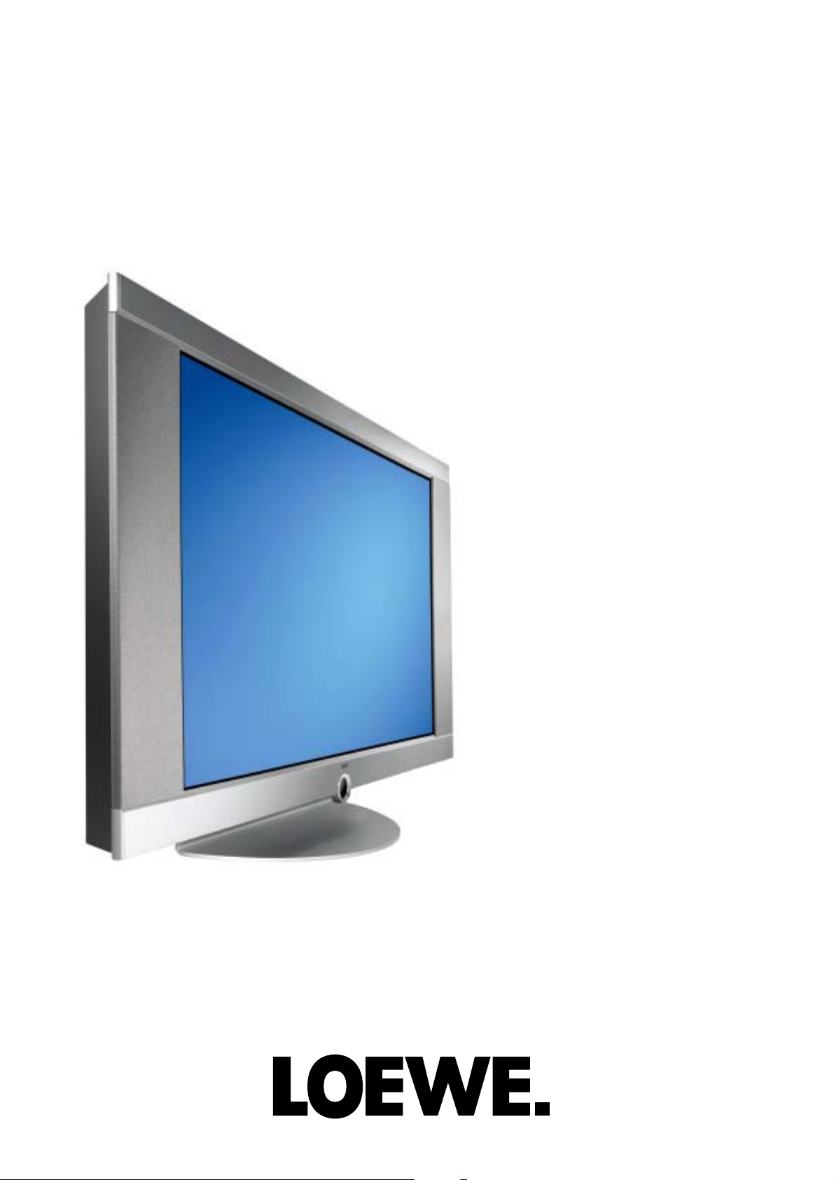
L 4200
230-90431.992
Concept L 42
Platinum
Art.-N° 64403A60
Concept L 42
Anthracite
Art.-N° 64403D60
Page 2

Table Of Contents
1. Introduction.................................................................................................................3
2. Service-address..........................................................................................................3
3. Technical Data ............................................................................................................4
4. Service-Hints...............................................................................................................7
4.1 Transport ................................................................................................................7
4.2 Cleaning .................................................................................................................7
4.3 Test patterns ...........................................................................................................7
4.4 Ground straps.........................................................................................................7
4.5 OSD-Duration.........................................................................................................7
4.6 Reset ......................................................................................................................7
4.7 Factory defaults......................................................................................................7
4.8 General Reset ........................................................................................................7
4.9 Overtemperature- switch off ...................................................................................7
4.10 Software-Update...................................................................................................8
4.1 1 Typical Faults........................................................................................................8
4.12 Flat-display connectors.........................................................................................9
5. Wiring diagram .........................................................................................................10
6. AV3 Signalprocessing..............................................................................................11
6.1 AV3 wiring diagram............................................................................................... 11
6.2 In-/Outputpanel..................................................................................................... 11
6.3 Connectors ...........................................................................................................11
6.4 Fault finding..........................................................................................................12
7. Startup Sequence .....................................................................................................15
8. Service OSD ..............................................................................................................16
8.1 Submenus ............................................................................................................16
9. Plasma Display.............................................................................................................19
9.1 Rear view including PCBs ....................................................................................19
9.2 Schematic Configuration ......................................................................................19
9.3 Power Supply Unit (PSU) .....................................................................................22
10. LVDS-Interface-Board ..............................................................................................23
11. Exploded Drawing ....................................................................................................24
12. Spare Parts List ........................................................................................................25
2 Technical Manual
Page 3

Introduction
1. Introduction
This manual is only intended for technically trained personel!
It was designed to enable the technician to carry out repairs on board—level in case of malfunction. Attempts
of repairs going on component level or, due to missing knowledge, will cause follow up defects, will lead
automatically to lapse of any warranty claims. The manufacturer reserves the right to check units, having been
returned for repair, to that effect.
In the case you should need support via telephone, please keep ready the ident—no. and the serial—no., both
can be found on the type label, located on the rearside of the unit, close to the mains inlet.
If you will have to return a defective unit for repair, please attach a detailed fault description, including when
and how the problem appears ( e.g. always after swichting on, sporadically, etc.)
In the unlikely event a problem should be unreproducible in our workshop, we immediately would like to get in
contact with you. For this reason it is very helpful if in the delivery note, besides the fault description, also a
technical contact person (incl. telephone—no.) is mentioned.
2. Service-address
Loewe-Service und Logistik
LOEWE OPTA GmbH
Service + Logistik
Zentrale Kronach
96305 Kronach • Postfach 1554
96317 Kronach • Industriestraße 11
When working at respectively inside the device, always
disconnect mains inlet!
There are dangerous voltages inside the unit. The
regulations
and safety instructions according to VDE
shall be valid as well as the respective national
deviations!
Keep to ESD regulations!
Die wichtigsten Rufnummern der Zentrale Kronach:
The most important phone numbers of the Kronach headquarters
Telefon: FAX
Ersatzteilbestellungen: (01 80) 522 1800 (01 80) 522 1806
Status von Reparaturen: (0180) 522 1805 (0 92 61) 99 412
Support TV Röhre: (0180) 522 1801 (0 92 61) 99 730
Support Video/DVD: (0180) 522 1802 (0 92 61) 99 730
Support Telekommunikation: (0180) 522 1803 (0 92 61) 99 730
Support HiFi: (0180) 522 1804 (0 92 61) 99 730
Support TV Plasma, LCD, Rückprojektion: (01 80) 522 1807 (0 92 61) 99 730
Note!
Spare parts orders only through Service + Logistics / Headquarters in Kronach
Technical Manual 3
Page 4

Technical Data
3. Technical Data
CONCEPT L 42
Display:
Model: PDP42V6####
Display Type: AC—PDP, V6
Screen size: 107 cm (42”)
Active screen (h x b): 920,1 mm x 518,4 mm
Aspect ratio: 16:9
Physical Resolution in Pixel: 852 x 480
Colors: 16,77 Mio.
Maximum Brightness: typ. 1000 cd / m2 (white peak @ 4% display load)
Maximum contrast ratio: typ. 3000:1 (dark room, white peak @ 4% display load)
Viewing angle (A/B, L/R): 800/800 , 800/800, typ.
Limitation power consumption: APC (Automatic Power Control)
Color temperature: 9500K (@ 20% grey) characterictics acc. to manufact. spec,
2—point adjustment not possible.
A.m. values are valid after 20 min operation at an ambient temp. of 25°C.
EMI Shielding Glass:
Type: Security Shatterproof Glass incl. Mesh
Transmission: 48% +/— 5%
Power requirement:
Mains Inlet: 115 — 230V ~ +/— 10%
Mains frequency: 50/60 Hz +/— 6%
Power consumption: 5W typ. in Standby, ca. 350W in operation
Inrush current: 40A max.
In— / Outputs:
Description Input / Output Signal
Cinch / Cinch: disabled no function
Cinch / Cinch: output Audio Subwoofer Line out / n.c.
Cinch / Cinch: output Audio Stereo Line out
Cinch / Cinch: input Audio Stereo for CVBS / YUV
Cinch / Cinch: input Audio Stereo for PC
Cinch / Cinch: input Audio Stereo for Y/C (S—Video)
DVI—I: input PC Connection to DVI—/ VGA—Signalsource
IEC: input RF antenna signal terrestrical or cable
IEC: output RF with patch cable connected to:
IEC: input RF
D—Sub 9pol: input / output PC RS232 for Softwareupdate
3x Cinch: input Video YUV, combined with CVBS
Euro AV: input Video CVBS, RGB, Audio L/R
output Video CVBS, Audio L/R
Euro A V : input Video CVBS, Audio L/R
output Video CVBS, Audio L/R
Input signals in PC Mode
Horizontal frequency range: 30kHz ... 80kHz
Vertical frequency range: 50Hz ... 90Hz
Pixel Clock frequency: max. 140MHz RGB, max. 110MHz DVI
Signal level, nominal: 0,7Vp—p +/— 3dB bei 75 Ohm
Synchronisation: SoG, Composite Sync, H— und V—Sync, separated
Sync. polarity: positiv and negativ
Sync. level: TTL, Loeding >1kOhm +/— 10%, bei SoG 0,3Vp—p +/— 0,015V,
negativ
VESA DDC Standard: 2B
Jitter: <6% @ 140MHz
Input resistance: 75 Ohm +/— 10% (0 ... 200MHz)
Threshold timing determination: +/— 2% (horizontal, vertical)
Transit time between 2 Timings: < 5sec
4 Technical Manual
Page 5

Technical Data
Displayable resolutions in PC Mode (analog)
170 pre—defined Timings, e.g.
DOS 640 x 480 60Hz
DOS 720 x 400 70Hz
VGA 640 x 480 50Hz to 90Hz
SVGA 800 x 600 50Hz to 90Hz
XGA 1024 x 768 50Hz to 90Hz
Formats in PC Mode (analog)
1 1:1
2 Format filling
3 User Zoom (40% to 140%)
4 Full screen
Input signal in PC Mode (digital)
Standard: DVI 1.0
Pixel Clock Frequency: max. 110MHz
Input signal in Video Mode
Standards: PAL: B/G, DK, I, M, N
SECAM: B/G, DK/K1, L/L’
NTSC: M4, B/G4, D/K4, I, NTSC—V (4,43)
Signal types: YUV, CVBS, Y/C, RGB
CVBS Signal level, nominal: 1Vp—p +/— 3% @ 75 Ohm
RGB Signal level, nominal: 0,7Vp—p +/— 3% @ 75 Ohm
Y—Signal level, nominal: 1Vp—p +/— 3% @ 75 Ohm
U—Signal level, nominal: 0,7Vp—p +/— 3% @ 75 Ohm
V—Signal level, nominal: 0,7Vp—p +/— 3% @ 75 Ohm
C (PAL) Signal level, nominal: 0,3Vp—p +/— 3% @ 75 Ohm synchronous color signal
C (SECAM) Signal level, nominal: 0,286Vp—p +/— 3% @ 75 Ohm synchronous color signal
Automatic format identification: WSS, BLD
CVBS Prozessing: Digital comb filter
Synchronisation: Analog and automatical sync recognition
Sync types: Composite, SoG
Sync levels: 0,3Vss +/— 3dB /75 Ohm
Formats in Video Mode
1 4:3
2 16:9
3 Zoom (130%)
4 User Zoom (40% to 140%)
5 Full screen
6 Panorama Zoom —> Cinema
7Auto
Displayable standards in RF Mode
CVBS Signals: PAL: B/G, DK, I
SECAM: B/G, DK/K1, L/L’
RF footprint: 47MHz to 861MHz (VHF / UHF / Hyperband)
Channel setting in RF Mode
Channel setting: Automatical channel search
storing and manual adjustment
Program locations in memory: 99
channel sorting: yes
Videotext
Videotext: TOP/FLOF, Level 2.5
Number of pages in memory: 2100
VPS: no
EPG: no
Audio Signals
Audio level Stereo inputs: 1Vrms
Audio level Stereo Line output: 1Vrms +6dB / —20dB adjustable via OSD
Frequency range (Line in / Line out): 20Hz to 20kHz
Technical Manual 5
Page 6

Technical Data
Audio settings
Equalizer: yes, 5 fader
Treble, bass: not available
Speaker
Quantity: 2 per side
Frequency range: 100Hz — 20kHz, —3dB
Output: > 5W nominal output / speaker
Impedancy: 4 Ohm /Spk, serial connection to 8 Ohm
Dimensions and weight
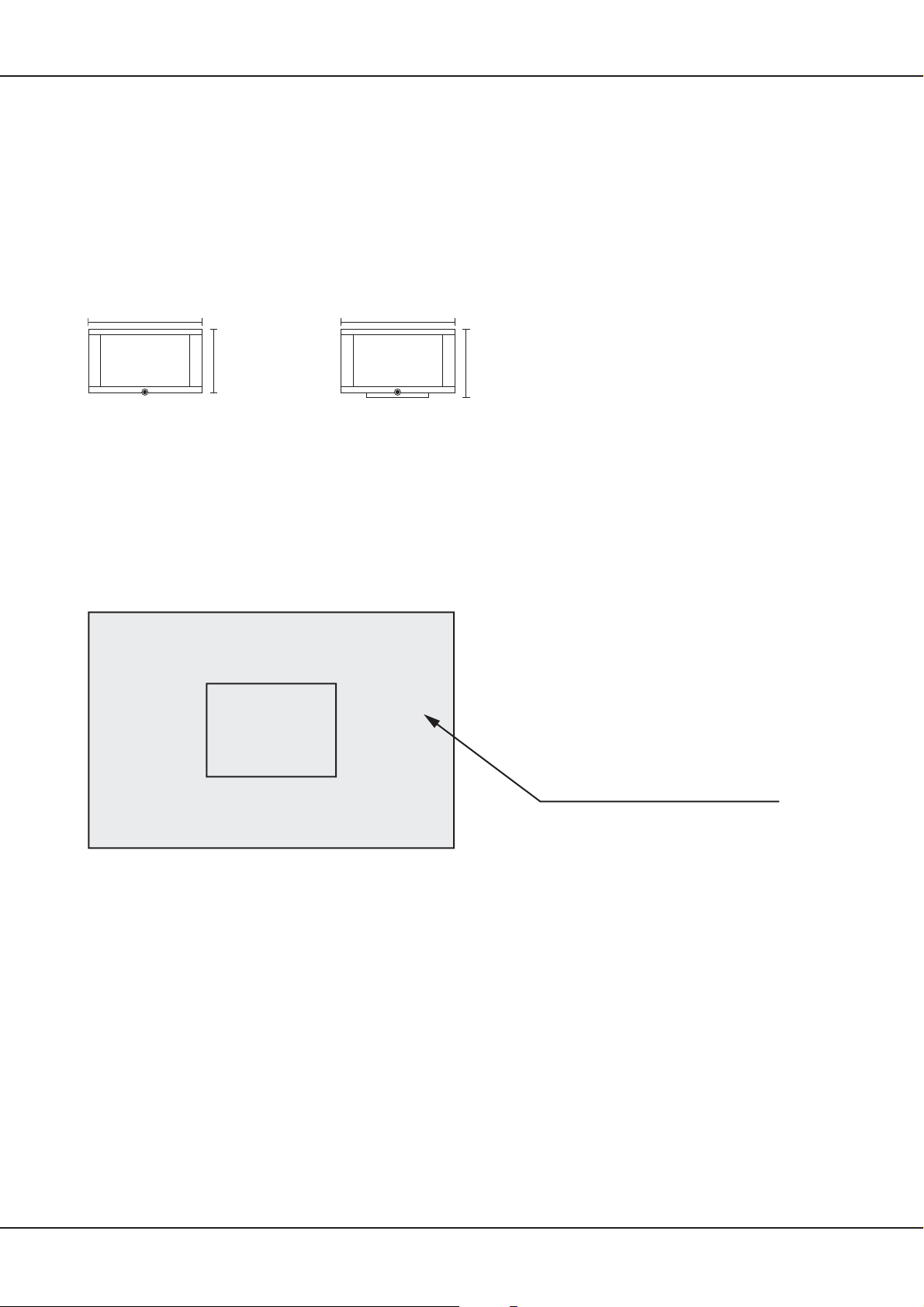
Dimensions with and w/o stand:
116,7
116,7
62,8
depth 9,4
Weight w/o Fuß: ca. 30kg
Weight incl. stand: ca. 35kg
Pixelfaults
Allowed Pixelfaults: According to manufacturer’s spec for the used PDP
(6 dark in A+B, 2 bright in B)
depth 21,8
70,7
A-Zone
25% of
Display Area
B-Zone 75% of Display Area
6 Technical Manual
Page 7

Service Hints
4. Service-Hints
4.1 Transport
The displays may only be transported in upright position! For the transport you have to take care for a save
pakking, for this the original packing, which is available at your LOEWE service (
suits best.
4.2 Cleaning
For cleaning of the surface a dampened, lint—free cloth is most suitable. As cleaning liquid the manufacturer
recommendsenvironmental friendly glass cleaner.
Most suitable for the claening of the ventilation openings is a handheld vacuum cleaner, cleaning by means of
compressed air is not recommended, as dust might get into the unit.
4.3 Test patterns
When using AV3 signal processing, test patterns are available under the service menu
page 16)
4.4 Ground straps
Ground straps, which connect the display with the housing of the unit, must be refitted after repair, to keep to
EMI regulations. Straps, which have been torn apart when removed, have to be substituted.
See chapter 2. on page 3)
(see also chapter 8. on
4.5 OSD—Duration
For Service it is helpful, to set the duration for the OSD to ”off”. The menues will then not disappear automatically
(see also Operating Manual)
4.6 Reset
On malfunction or when the device has ”stuck up” (no control via IR possible anymore), switch off unit via
mains power switch — wait for 30 sec (until all electrolyt—capacitors are discharged) — switch on unit again.
4.7 Factory defaults
In the OSD—menu under submenu ”function” you will find the item ”factory defaults”. All settings will be set to
factory presets, the channel storage remains
(see also Operating Manual).
4.8 General Reset
In the service menu (open with ”8640”,
complete reset can be done.
CAUTION: Here the operating hours as well as the channel storage will be erased!
see also chapter 8.1.6 on page 17)
under the submenu ”reset all” a
4.9 Overtemperature— switch off
”WARNING” will appear, as soon as the temperature on the AV3 electronics exceeds 60°C (Temperature 1)..
The unit will be switched to Stand By, the red LED is lit as soon as the temperature on the AV3 electronics
exceeds 65°C (Temperature 2). It is possible to switch on the unit again via remote control.
The unit will be switched to Stand By, the red LED starts to blink as soon as the temperature on the AV3
electronics exceeds 70°C (Temperature 3). It is not possible to switch on the unit again via remote control.
As soon as the temperature is below 60°C, the LED stops blinking, it is possible to switch on the unit again
(see also chapter 8.1.4 on page 17)
.
Technical Manual 7
Page 8

Service Hints
4.10 Software—Update
You need:
— Update—Program ”FlashUpgrader.exe” (for Windows 98 and Windows ME) or ”FlashUpgraderNT.exe” (for
Windows NT4.0, Windows 2000 as well as Windows XP). Under Windows 95 the update is not possible.
— actual software (the update software as well as the actual software release for your device is available as
zip—file at your LOEWE service,
— Null—Modem cabel (serial date cable (RS232) with 9 pin female connector on both sides, the wires must be
crossed)
Update:
— Unpack Update—Program and new Software into a new directory.
— Switch off unit (mains switch).
— Start Update—Programm.
— Select via ”Choose...” file ” *.inf” in the new directory with the firmware data.
— Set ”Connection” to ”serial”, select the used Com port as well as the Baud—rate (recommended 115200).
— All other options remain on ”default” position.
— Click on ”Flash” anklicken, the program is set to stand by
— Switch on the device using the mains switch. The program starts automatically, the progress is shown on
the display. Depending on the selected Baud—rate, the update takes about 3—6 minutes.
4.11 Typical Faults
In the case of malfunction, it is recommended to check the external wiring before opening the unit:
— Mains power available?
— Are the corresponding signal cables connected?
— Is there a signal available from the external sources?
— Is the corresponding signal source selected?
Also after opening the unit it is recommended to check the internal wiring and connectors to exclude any loose
contact.
see chapter 2. on page 3
)
4.11.1 No display (on all signal modes)
— Check In—/Outputs of power supply
(see chapter 9.3 on page 22)
4.11.2 Not possible to switch unit on (remains in StandBy)
— Check IR remote control (batteries!)
— Reinstall software
— Check AV3—electronic
(see chapter 4.10 on page 8)
(see chapter 6.4 on page 12)
4.11.3 Missing lines or columns
— Check display
(see chapter 9. on page 19)
4.11.4 Pixel faults
Due to technological reasons single pixels or subpixels might fail on TFTs as well as on Plasma displays. As
long as the number of faults is within the limits mentioned in the specification, there is no device defect
existent
(see chapter 3.on page 6)
.
4.11.5 Missing colors
— Check data cable
— Check AV3
— Check display
(see chapter 6. on page 11)
(see chapter 6.4 on page 12)
(see chapter 9. on page 19)
4.11.6 Channel search not working / not working properly
— Check AV3
(siehe chapter 6.4 on page 12)
8 Technical Manual
Page 9

Service Hints
4.12 Flat—display connectors
If there should be a repair or just a check on a LCD— or Plasma—panel, it will become necessary to disconnect
some of the connectors. Sometimes this is quite complicated, disconnetion only with force will lead to total
defect of the panel in the worst case. Below there are the most common connectors and how to disconnect
them:
Lift upwards
before disconnecting unlock by pressing
to unlock pull towards arrow direction
take care for rest noses!
to unlock fold towards arrow direction
Technical Manual 9
Page 10

5. Wiring diagram
P1031
90432.900
LG Electronics
42 ” Plasma Display
PDP 42V6.....(LG KK)
P2008P2005P3001
4 pol
4 pin
CN805CN806CN807
10 pol
10 pin
Logic Board
8 pol
1 GND 13 GND
2 RA- 14 GND
3 RA+ 15-18 n.c.
8 pin
Wiring, premounted
Verkabelung, vormontiert
4 RB- 19 GND
5 RB+ 20-25 n.c.
6 GND 26 GND
7 RC- 27 DISPEN
8 RC+ 28 SDATA
9 RCLK- 29 SCLK
10 RCLK+ 30 SLE
11 RD- 31 GND
12 RD+
P31
Connector
Signal Input
4 X
00
Kantenschutz
? X
Driller
300lg
90432.924
? X
2 X
00
Kantenschutz
Klebeschellen
Netzteil Bestandteil des PDP
Power Supply Unit (PSU) Part of PDP
Bolzen für Erdung, Zahnscheibe verwenden
Earth over bolted assembly, use a toothed lock washer
L
N
1
2
CON1
roter Sockel
150lg
PE
Part of PDP
Netzeingang
(Bestandteil PDP)
Power Input
Part of (PDP)
90432.918
1 ACD
red socket
100lg
Netzschalter
Power Switch
2 RLY ON
1a
2a
3 +5Vst_by 1,2,3 +5V
4 GND 4,5,6 GND
5 Vs ON 7,8 +12V
CN02
112
Power
6 5VD 9,10 GND
7 n.c. 11,12 n.c.
+5VSB and
Audio
1,2 30V
3,4 GND
CN03
300lg
Ansicht der Netzschalter-Kontakte
230 V~
5V / 12V
PSU control
Power
CN802 CN801 CN803
1a
2a
View on the power switch contacts
90432.921
90432.920
2
Pin Leitung / wire
1a 0921-0204-6501D3
200lg
90432.922
6774
300lg
90432.923
300lg
650lg
1 2215-1146-0001 (braun / brown)
2a 0921-0204-6501E3
2 2215-1146-0001 (blau / blue)
Power +5V/+12V in
Control
CN8
Keyboard
CN11 CN19 CN13
Audio
10 pin
7 pin
7 pin
Power in
X1
90432.902
LVDS-Adapter
1 +5VST
2,4,6 GND
3,5 +5V (VCC)
7 +12V
8 PSSTDBY
9 PSDPMS
1 ACPWCK
2 RLYON
3 5V STBY
4 GND
5 VSon
6 FPVRR
1,7,18 GND
3 LED (rt/rd)
4 LED (grn)
19 +5VST
20 IR Rec
J7
4 pin
1,2 GND
3,4 30V
X1
IR-Receiver
LED grn/rt // grn7rd
X1
1 GND 11RD+ 19 GND
10 FPVRR
7 n.c.
CN2
90432.903
2 DISPEN 12 RB- 20 R3+
3 SLE 13 GND 21 R3-
PIP-Tuner
AV3plusL
Scart 1
4 SCLK 14 RCLK+ 22 GND
5 SDATA 15 RCLK- 23 RA+
6 GND 16 GND 24 RA-
7-9 n.c. 17 RC+ 25 GND
f1
f2
f1
90432.901
L
Scart 2
10 GND 18 RC-
CN29
CN20
R
140lg
90432.919
Folie 12 cm Kontaktblech
LS-L
2
2
4 Speakers 4 Ohm
--
++
++
--
LS-R
90432.908
10 Technical Manual
Page 11

6. AV3 Signalprocessing
6.1 AV3 wiring diagram
Speakers Out
Cinch
Audio Amplifier
TDA 7263
Sound Ouput
1x Cinch & 2x Scart
Image Processor
Main CPU
Flash ROM
1 MByte
Display Port 48Bit
AV3 Signalprocessing
SDRAM
2 MByte
Flash ROM
2 MByte
Teletext Engine
SDA 6000
Sound Processor
(ADC/DAC)
MSP 3410G
Audio Matrix
Sound Input
3x Cinch & 2x Scart
VGA/HDTVp In
1x analog & 1x DVI
6.2 In-/Outputpanel
NC
LINE
OUT
SUB
LINE
OUT
CVBS/YUV
LINE IN
S-VIDEOPC
PW 181
VGA ADC
& DVI Receiver
AD 9887
PC DVI-I
RS232
DSUB
RF IN
RF OUT
RS232
2x RF-
Tuner
ANTENNA
Video Decoder
& PIP Engine
& Video Matrix
(embedded RAM)
VSP 9417
YUV
Video Input
SCART 2
SCART 1
S-VIDEO
3x Cinch (YUV), 1x MiniDIN, 2x Scart (RGB)
CVBS
6.3 Connectors
Below please find the most important connectors. For clarity reasons only those connectors are
mentioned, which are in use.
Connector
CN 1
CN 4
CN 6-C
CN 22
CN 5
CN 3-A
CN 3-B
Technical Manual 11
Pin Marking
2x Scart, Scart1 also RGB fit
S-Video
CVBS
RS-232
DVI-I
PC Audio in
YC Audio in
Page 12

AV3 Signalprocessing
Connector
CN 15
CN 6 -A/-B/-C
CN 21
CN 11
CN 13
CN 33
Pin Marking
CVBS/YUV Audio in
YUV
1,5,7
2
3
4
6
1,2
3,4
1
2,4,6
3
5
7
8
9
10
1-50
GRLED (green LED)
STBY (start low voltage)
DPMS (start high voltage)
GND
5V Standby
IRRCVR (Sensor)
RDLED (red LED)
GND
30V Audio
5V Standby
GND
5V
5V
12V
VRR (PD Pready)
Digital Output
6.4 Fault finding
6.4.1 Without opening the unit
— Analysis Front LEDs
Red LED remains lit in spite of switching unit on with remote: device stays in standby, possible faults are IR
remote control or AV3..
Green LED but no picture: device is active but shows no image, possible faults are: wrong input source
selectedor panel defective.
Red and green LED is lit at the same time: unit is in an undefined state, fault caused mostly by AV3
— Analysis Screen
If with a black screen (no image is displayed) a light gleam is still visible (darken point of view with hand),
normally the problem is located in the signal routing and not on the panel itself.
.
— Accoustic Analysis (Relais)
When switching between the different input sources, there is a gentle click of a relais to be heard. If this is not
audible, the problem is certainly located on the AV3.
6.4.2 With open unit
— Check supply voltages (use the pins of the connectors for testing points,
— Problem containment (by means of checking and / or exchange of single PCB’s)..
(see chapter 6.3 on 11)
.
6.4.3 FAQs
Noisy picture in tuner mode
— Signal level must be higher than 68dbµV (typical level of cable TV)
— High noise level on RF signal (poor SNR)
— Adjust DNC to max. (OSD)
— Due to the digital signal processing flat panels are more sensitive to noise levels than 50Hz interlace CRTs
or 50Hz progressive CRT s (8Bit resolution, False Contouring, Dithering, Deinterlacing, limits of the used PDPs,
...)
Noisy picture in Video mode
— High noise level on Video signal (poor source)
— Adjust DNC to max. (OSD)
12 Technical Manual
Page 13

AV3 Signalprocessing
—
Due to the digital signal processing flat panels are more sensitive to noise levels than 50Hz interlace CRTs or
50Hz progressive CRTs (8Bit resolution, False Contouring, Dithering,Deinterlacing, limits of the used PDPs, ...)
— If possible do not use FBAS signals, better is SCART—RGB or S—Video.
Regular horizontal or vertical stripes in Video picture
— Change position of external signal wiring (emission of PDPs)
— Humming loop (ground shift)
Video picture only in black and white
— Poor signal level or non—standard signal
— Signal not supported (e.g. NTSC via RF)
At channel search, not all channels are recognized or recognized with the wrong name
— device is not supporting PDC
— device is working with internal channel name table, if the channel name changes shortly, this may lead to
wrong information
Image is flat and low contrast (Video/VGA)
— The factory defaults for brightness and contrast are suitable for most applications, only for exceptions this
settings should be changed
— Also other settings and adjustments might influence the picture quality, for this reason always first reset to
factory
defaults (OSD—Menu)
Picture out of focus in VGA—Mode
— Max. resolution of 848x480 is recommended
— in rare cases (poor signal quality or unfavourable display), auto—adjustment is not able to work correctly
(see Operating manual), select manual adjustment in the OSD
— Adjust focus in menu Picture to the signal source
Technical Manual 13
Page 14

AV3 Signalprocessing
U22
C92
R483 R482R71
C513
C123
C120
C110
VR3
VR8
R80
R79
R127
R491
+
C521
RN23RN22RN21RN20RN19RN18RN16RN15
R494
C417
+
R94
R90
X2
C106 C116
+
R449
R164
R362
C66
C51
C56
RN17
R389
C469
U32
C345
C331
U39
C100
D3
+
C420
R91
R92
C124
+
R83
C186 C170 C268 C180
C147
C107C103
TP45
TP44
+
C230
C184
C148
R147
+
C87
C146
+
C121
R106
R105
R104
U18
R103
R102
R101
R100
R99
R449
TP4
C115
TP5
C40
R53
R30
R358
C55
+
C515
R436
C55
TP7 TP32
C525
+
C526
C36
C52
+
C57
TP16
R315
R322
Z2
R462
R365
R364
R282
C144
C410
C411
J10
TJ1
T8
T7
C111
C91
U19
C530
L9
C496
R272
R383 R388
R381
R308
C236
R76
R93
R88
C253
C209
RN51RN50RN49RN48RN47
C183C131
TP12
R229
C191
VR7
C133
+
C185
L35
R148
C205
C249
R233
R230
+
RN61
C186
C178
C263
C252
U16
L22
C345
C145
R394
C138C473
U41
RN25
C472
C139
C469
U26
C232
C377
CN7
C70
TP38
TP37
C201
+
C214
+
C194
C200
C199
C198
RN46RN45RN44
C197
C226
L16
R136
TP15
L23
C528
C175
C190
C213
C212
C351
R133
C189
L24
C208
R132
+
C193
C207
U23
C206
R131
R124
+
++++
C196
RN30
R143
C225
C239
C236
C218
C161
C229
C228
++
TP30
R231
R232
C179
C286
C306
C142
C132
X3
C117
T22
RN30
R251
TJ5
+
C124
+
TJ7
TJ8
C220
R492
C361
C478
C392C391
C244
L21
C181C182
R129
C203
R130
R204
T10
R152
C259
C276
R153
C217
C211
C114
R182
R138
C216
C262
+
C247
C479
R123
R125
C210
C202
C117
C258
C195
R126
C257
C186
R111
R114
C225
RN41 RN63
R215
T11
R151
R228
C222
R140
R217 R216
R142
R218
T13
R150
L15
R155
+
C271 C248
R174
C172
C288
R174
C399
+
C342
L31
L32
C282
C283C219 C373
L34
C505
C344
C503
+
C476
C475
C504
C477
C502
C285
C343
R122
RN38 RN34 RN31
TP33
+
M12
RN64
+
CN10
+
R480
C337
C335
R145
C241
TP14
C240
R160
TP17
R144
C250
C238
C224C223
+
+
C237
C231
++
C251
C265
C533C536
C278
C269
+
TP46
RN60RN59RN58RN57RN56
C300
C304
C273
U27
C261
C329
C303
C292
R166
T14
C268
R167
+
C328
L29
R159
C260
C277
C326C299
R163
C325
R190
+
C298
C324
C323
R189
C267
R188
C322
C321
C297
R187
C320
R186
C319
C296
C318
R185
C317
R184
C316
C315
C295
C226
R183
C314
+
R177
R172
C272
C313
+
VR5
C109
C105
R81
R70
C104
C7
R69
TPG1
+
TG2
L72
L73
L70
R247
C360
L68
L47
L67
C359
R262
L69
C370
C348
L61
L48
L71
R239
L63
L60
R379
R378
R439
C151
C371
R263
C527
L49
C338
R248
L12
R440
R258
R284
R287
C137
D11
R297
R240
R310
U12
R305
C362
L50
C393
R301
C419
C447
R304
C418
R309
C455
+
L77
C112
+
C291
L46
+
R222
T33
C440
U1
C125
R486
R170
R180 R196 R211
R485
R171
R181
R175
R484
R395
R156
R162
R166
U28
C275 C254 C234
TP19
TP21
R221R451R490
R210
C18
R226
R452
C281
C332
+
++
C357
TP11
R396
CN28
+
+
+
C270
R115
R393
+
C408C407
+
+
C400C334
R457
R448
C430
CN9
R493
R359
R282
R269
R256
+
R475
C119
R161
R281
R443R444R445
C489
C406
R256
C532
C375
C352
C534
TP24
TP6
C429
+
C396
C330
C333
C389
+
C388
R280R279R278
R293
C387
R461
R292
C386
R291
C385
R460
R459
C384
R416
C383
C382
C381
C380
C415
R470
C379
C260
VR10
C368
R472
C368C341
C414
+
C367
R227
R277
R226
R250R249
C404
C340
C366C365
R276
R225
TP23
R213 R214
C403
C339
C472
+
L44
U31
T23
C435
+
L42
R242
C395
C402C401
R265
C364
R242
TP22
C351
R255
R275
T21
T25
R254R252
R224
C394
R264
R241
C363
C350
R223
R253
R274
T20
T24
R82
C82
C75
R346
TP43
U20
TP9
RN62
TP28
C167
+
M3
X7
C187
R455
R456
RN36 RN53
C305
CN23
C274
C234
C166
C246
L27
R154
R453
R454
R109
R117
+
R108
C155
J3
+
C474
+
C242
C345
+
C143 C37
C501
C233
C284
R110
R33
C279
R399
R32
X6
R398
R397
R400
C280
R401
C152
L28
C154
RN42
RN52
C374
TP18
C129
C76
R450
C67
C6
R8
R9
U40
R273
T38T39
R386
R380
T37
R385
T36
J9
+
C141
C287C160
C94
R75
+
C153
RN39
RN33
RN40
RN32
C171
+
R112
T41
R409
R113
R407
R408
T42
R406
TP13
C227
R479
TP39
TP40
C428
+
L54
C21
C163
+
R469
VR4
C176
R467R468
C164
+
R330
T40
R325
R314
R390
L14
C130
R391
R384 R387
L11
C174L13
C162
R119
C157
T9
R121
+
R437
R116
TP27
TP42
X4
C150
C156
TJ2
TJ3
TJ4
R363
R11
R372 R373
R118
R120
R74
C95
C149
C159
C173
C83
R72
R73
+
M18
+
M14
L62
L46
L65
L66
L58
L59
L57
L56
C441
+
M10
R212
C235
R134
C204
C349
R128
R202
R203
R139
C255
C192
R137R141
R146
C290C289
R176
C101
C431
C470
U34U33
+
+
MP1
C405
+
C442
U35
+
D15
D14
C422
C427
R471
R290
R300
R307
C413
C426
C439
R289
R299
R306
C412
C425
C438
+
C436
+
C446
C301C264
+
++
C445
CN29
CN20
C448
+
W1
TRG4
DDC
L1
R487
L88
C458C457
R343
R342
L87
C293
L39
L25
L40L45
L17L43
CN6 CN4
L75
CN22
L76
R323
+
M11
R530
R328
D21
L94
R327R326
L93
L92
L91
D20
L90
R344
D19
L89
D2
+
D18
C497
D16
+
W9
L84
R320
R340
C457
C453
L85
R321
R341
C468
C454
L82
R318
R338
C465
C451C452C450 C449
L83
R319R316R317
R339
C466
C463
R336
L80
C464
R337
L81
C462
R335
R334
L79
C461
C460
L78
R333
R332
C459
L53
CN14 CN15 CN3 CN5 CN27
F1 F2
R235
++
M13
7
U2
C29
+
R149C96
R153
VR11
C423
C122
+
+
C128
C424
R158
6
R347
RN43RN53
CN18
R415
R419
R420
R416
R418R414R411
R421
R423
R91
R417
C86C54
C69
R410
R5
+
C3
C220
U43
R2
C2
R4
R3
R34
R493
R270
R271
TP35
C433
+
C432
CN33
U42
R412 C127
C68
L41
R422R413
C511
+
R425
R427
R424
R426
C5
C22
R428
5
4
3
R429
U3
C27
+
+
C9
R348
R356
R357
L8
L7
C4
L6
L4
+
CN12 CN13
C12
TB25
M4
+
R473
R474
R62
T15
R40
R46
R41
R43
R374
R68
CN19
R375
R84
R57
T16
R58
R85
R67
L5
R12
R15
R14
R17
CN21
R283
C50
+
R466
R465
R464
VR6
+
+
C11
C10
+
R353
R352
T2
R24
R50
T50
R49
R55
R56
U4
C15
+
C14
+
C13
VR6
R351
C487
C488
R35
R27
R26
R463
R434
J1
C434
C17
C19
C33
R490
R489
R13R16
C444
C24
+
C443
C23
U24
C307
R488
CN8
2
R463
TP10
TRG2
L3
CN11
R329
R200
J7
R201
R478
C369
C27
R458
TG1
1
+
+
M2
M17
TP8
R234
R7
R59
TP36
R259
CN16
C1
R6
C471
T1T3
R1
R405
R404
R476
R477
+
M6
+
C90
VR2
C80
TP34
+
C85
C98
+
TP2
+
M8
RN1
C64
TP50
TP51
TP52
CN32
M5
++
M7
+
T44
T43
R20
R432
R433
R430
R431
R438R442
R206
R23
R311
T46 T45
R441
R25
R31
TP47
R313R296
+
C31
C30
+
+
MP2
+
C16
C28
T48
U30
R368
R369
R367R366C398
L2
VR9
R435
R209 R173
R237
D17
+
C93
C308
R208
U48
C81
R355
C32
C337
D12
C335
R198
R219
C347
C346
+
U37
D4
+
C397
+
L19
C529
L26
RN14 RN24 RN27 RN28
T32
D5
+
C74
C356
C336
T28
C353
R236
C354
C421
R207
C358
C355
R286R257
TP1
R107
R371 R370
J6
R29
R28
C39
R18 R19
J5
C409
R39
D1
R38
C38
J2
C37
C36 C486
F3
R199
CN2
+
R197
R196
C327
C302
R42
C312
U5
T4
U10
R48
R45
R44
R191
R302
C376
C26
C53
U11
C97
+
C84
C73
+
D10
D8
T17 T18
R179
R205
C60
J4
R285
C79
+
C63L10
R98
R78
C390
C59
C523
R86
C34
+
R10 R64
R47
C113
T5
R361
R360
R52
R51
U9
R195
C310
C309
R194
T19
T12
C302
R288
T47
R298
v
U17
C102 C158
C221
+
C78
C295
R261
C267
C294
C99
+
+
C61
C136R376R377
C88
C140
+
C506
C402C403
+
M16
C509
+
C507
R245
R178
C506
+
R244
R354
R60
R54
U13
C89
+
R481
C71 C72
U15
C65
CN117
R66
R87R89R392
C524
TP3
U14
R63
C49
C522
CN26
R238
R246
R65
C165
R447
R446 R77
RN29
CN24
U12
RN26
T6
R21 R22
R220
+
M15
C311
C108
R193
R167 R192
T35
R312
M19
R97R303
R95
Z1
R324
T34
D6
R96
D7
C135
D9
D13
HS1
++
AV3+
7
CN1
6
5
4
3
2
1
ZERO POINT
B B
C C
D D
E E
F F
G G
H H
I I
J J
K K
L L
M M
N N
O O
P P
Q Q
14 Technical Manual
A A
Page 15

7. Startup Sequence
Description and Pinning
Bolzen für Erdung, Zahnscheibe verwenden
Earth over bolted assembly, use a toothed lock washer
12L
N
CON1
roter Sockel
red socket
CN02
CN03
Netzteil Bestandteil des PDP
Power Supply Unit (PSU) Part of PDP
1 ACD
2 RLY ON
3 +5Vst_by 1,2,3 +5V
4 GND 4,5,6 GND
5 Vs ON 7,8 +12V
1,2 30V
3,4 GND
Audio
Power
CN802 CN801 CN803
6 5VD 9,10 GND
7 n.c. 11,12 n.c.
+5VSB and
PSU control
Power
5V / 12V
Startup Sequenze
CN805CN806CN807
Verkabelung, vormontiert
Wiring, premounted
90432.921
300lg
90432.923
300lg
CN11 CN19 CN13
Audio
Power in
4 pin
1,2 GND
3,4 30V
J7
CN2
CN8
Keyboard
7 pin
1,7,18 GND
3 LED (rt/rd)
4 LED (grn)
19 +5VST
20 IR Rec
AV3plusL
Control
7 pin
1 ACPWCK
2 RLYON
3 5V STBY
4 GND
5 VSon
6 FPVRR
7 n.c.
Power +5V/+12V in
PIP-Tuner
90432.901
L
R
CN29
CN20
6774
10 pin
1 +5VST
2,4,6 GND
3,5 +5V (VCC)
7 +12V
8 PSSTDBY
9 PSDPMS
10 FPVRR
X1
1 GND 11RD+ 19 GND
2 DISPEN 12 RB- 20 R3+
3 SLE 13 GND 21 R34 SCLK 14 RCLK+ 22 GND
f1
f1
5 SDATA 15 RCLK- 23 RA+
f2
6 GND 16 GND 24 RA7-9 n.c. 17 RC+ 25 GND
10 GND 18 RC-
90432.922
LVDS-Adapter
Startup sequence AV3 in connection with the PSU of the Plasma:
1. Step
On CN801 of the PDP PSU, Pin3, +5VDC appears.
200lg
90432.902
X1
Scart 1
Scart 2
2. Step
CN801, Pin1 (ACDET) switches to ”high”, as soon as the voltage from the PSU becomes higher than 90VAC. If the
voltage remains under 90VAC, the startup will stop here (is interrupted by the AV3).
3. Step
To start the plasma, the signal RYLON (CN801, Pin2) is set to 5V, which causes the startup of the low voltages on the
PSU, as e.g. 5V, 12V, 30V, etc.
4. Step
The signal 5VDET (CN801, Pin6) is under surveillance. If the signal is ”low”, the AV3 will setRYLON = 0V (this causes
the switch off of the panel).
5. Step
On ”high”—signal (RYLON = 5V) the AV3 will set VSON to ”high” (CN801, Pin5) and will switch also the high voltages,
the panel is under operation.
Technical Manual 15
Page 16

Service OSD
8. Service OSD
Beside the User—OSD there is an additional Service—OSD, in which settings and adjustments can be
made whichwill change the performace of the display, alternatively will show information which are helpful
for service. For this reason the access to this menu should only be familiar to suitablely educated persons.
To enter the service menu, first the user menu has to be opened (button ”menu” on your remote control),
afterwards you can enter the service menu by typing the code ”8640” on your remote control.
The following menu will appear (the values which are shown are only wildcards and will differ in most cases
from the effective values):
Version / System Info
RS232 setting 4800
Customer logo -1Operation Time
Default Color Setting
Power On Input PC (RGB)
Temperature Setting
Full Mask None
Sub Laustärke
Alles zurücksetzen
8.1 Submenus
The following items can be adjusted directly in the service menu:
RS232 Setting (option)
Customer Logo (option)
Power On Input
Full Mask
Here the download speed for an eventual software
update is set. If there are problems during an update. it
is recommended to reduce the speed.
In the internal memory of the AV—electronic logos of
different customers are archived. To avoid irritations,
this setting should not be changed.
This item defines the input source, which is activ when
the unit is started up. There are all input sources
available to chose from, additionally there is the
possibility of ”Last”. If this is chosen, the device will start
up autiomatically with the same source it has been in
when being switched off.
For service purpose (Pixelfault finding, check of Burn—
In effects) it is helpful to display a picture in Red, Green,
Blue or White. The selected mask is shown after leaving
the menu. When ÒInvertedÓ is selected, the actually
displayed image will be shown in inverted colors. This
function might be helpful to erase slight Burn—In effects
(the ”Burned—In” image must be available). Items,
which are not part of the above mentioned table, can
be set via the following sub—menus:
16 Technical Manual
Page 17

8.1.1 Version / System Info
Sub menu Version / System Info shows the actual
software version, the hardware version and the
audio processor type (MSP).
Ther are no adjustments possible. In all service
cases, where consultation with the manufacturer
should be necessary, for this information will be
asked.
8.1.2 Operation Time
Sub menu Operation Timeshows the operation
time of the complete unit (also standby) as well as
the operation time of the panel.
Via ”Reset” both values can be reset to ”0” . This is
necessary when, e.g. the panel has been
exchanged during repair.
CAUTION:
is no other possibility to assess the operating time
of the device. It is highly recommended to record
the operating time in written form in the repair form
or in different form (e.g. photograph).
If here the values are reset to ”0”, there
Service OSD
Sofware % z
Sofware % z
Hardware % z
Hardware % z
MSP % z
MSP % z
Operation Time % z
Panel Time % z
Reset
8.1.3 Default Color Setting
In sub menu Default Color Setting the basic
adjustment of the colors for all input sources is set.
The offset value defines the color temperature for
the complete display, including the background, the
gain-value influences the colors of the image
content.
As a basic principle it should always be tried to do
any color adjustments via the user—menu, for
certain applications, however, it might be
necessary to do adjustments in this menu (e.g.
applications in T.V.
producing branches).
8.1.4 Temparature Setting
The AV3—electronics contains an implemented
temperature—control, which consists of three
steps
(see chapter 4.9 on page 7)
made values are for optimum operation of the
device and should only be changed in extreme
individual cases after consulting the manufacturer.
Any defects, caused by unauthorized changes in
the temperature control, will automatically lead to
loss of any warranty claims.
For service purpose it is possible to reset the
Max.— / and MIN.—Temperature. This allows to
check, if the unit moves towards critical
temperatures at certain applications.
. The factory—
Rot Offset -123-
Red Offset -123Grün Offset -123-
Green Offset -123Blau Offset -123-
Blue Offset -123Rot Gain -123-
Red Gain -123Grün Gain -123-
Green Gain -123Blau Gain -123-
Blue Gain -123-
Temperature 1 -12.3Temperature 2 -12.3Temperature 3 -12.3Max. Temp. All Time -12.3Min. Temp. All Timer -12.3Reaet Max/Min
Technical Manual 17
Page 18

Service OSD
8.1.5 Sub Volume
Sub—menu Sub Volume sets the pre—adjustment
for the volume of all input sources, respectively Line
out Audio.
Factory—made all levels are set to the same value,
in some cases the output levels of some peripheral
devices on customer side might be different. For this,
the customization can be done here.
8.1.6 Reset Everything
With Reset Everything all adjustments, the channel
memory, the Max.— / Min.—Temperatures as well
as the Operating hours will be reset, which means
the device is in the same status as originally delivered
by the manufacturer.
This should only be done after consulting the
manufacturer, as with the erased temperatures and
operating hours important information will be lost
which might be necessary for warranty claims.
CVBS -12PC -12YC -12SCART1 -12SCART2 -12TV -12YUV -12Subwoofer -12Volume ”Audio Out” -12-
18 Technical Manual
Page 19

9. Plasma Display
Following you will find the description of the Plasma Display Type PDP 42V6####.
9.1 Rear view including PCBs
Plasma Display
E/X Tube
1234567
Type Labels
Flex Cable
Y-SUS
Controller
Signal Input
X left X right
(R, G, B, H/V Sync)
Z-SUS
If a repair exchange has to be carried out, special care has to be taken of the so called E/X Tube. Via this
sealed glass tube the panel is bleeded first, after that it becomes filled with gas. If this tube becomes broken,
the panel is totally lost. Also when changing the panel, take care of the flec cables, any damages will also lead
to a total loss of the panel, as those cables are bonded between the glass layers of the panel.
On the so called T ype Labels you will find the panel type and the serial number of the panel. This information
should be noted on the delivery notes in case of repair exchange.
9.2 Schematic Configuration
The schematic configuration of the panel shows, which PCBs belong together and which signals are conducted
to the panel. The mentioned voltages Vs, Va and Vcc are from the PSU, which is part of the panel. Any
exchange of the PSU by untrained persons is not recommended, as the voltages on the PSU have to be
adapted to the correspondingpanel.
Technical Manual 19
Page 20

Plasma Display
(LVDS Input)
RxD+
RxDRxC+
RxCRxB+
RxBRxA+
RxARxCLK+
Serial Interface
Input
Interface
Controller
Scan Driver
Memory
Controller
Driver
Timing
Controller
Color Plasma
Display Panel
852 x 480 pixels
Vs (180V~190V)
Va (55V~65V)
Va (+5V)
Applied V oltage
level is specified at
the thime when full
white pattern
displayed on panel.
Adress Driver
Common Sustain Driver
20 Technical Manual
Page 21
Plasma Display
9.2.1 Life Expectancy
The anticipated life—time is estimated about 60.000 hours of continuous operation. Average life—time is the
time when the brightness level becomes half of its initial value.
9.2.2 Typical Faults
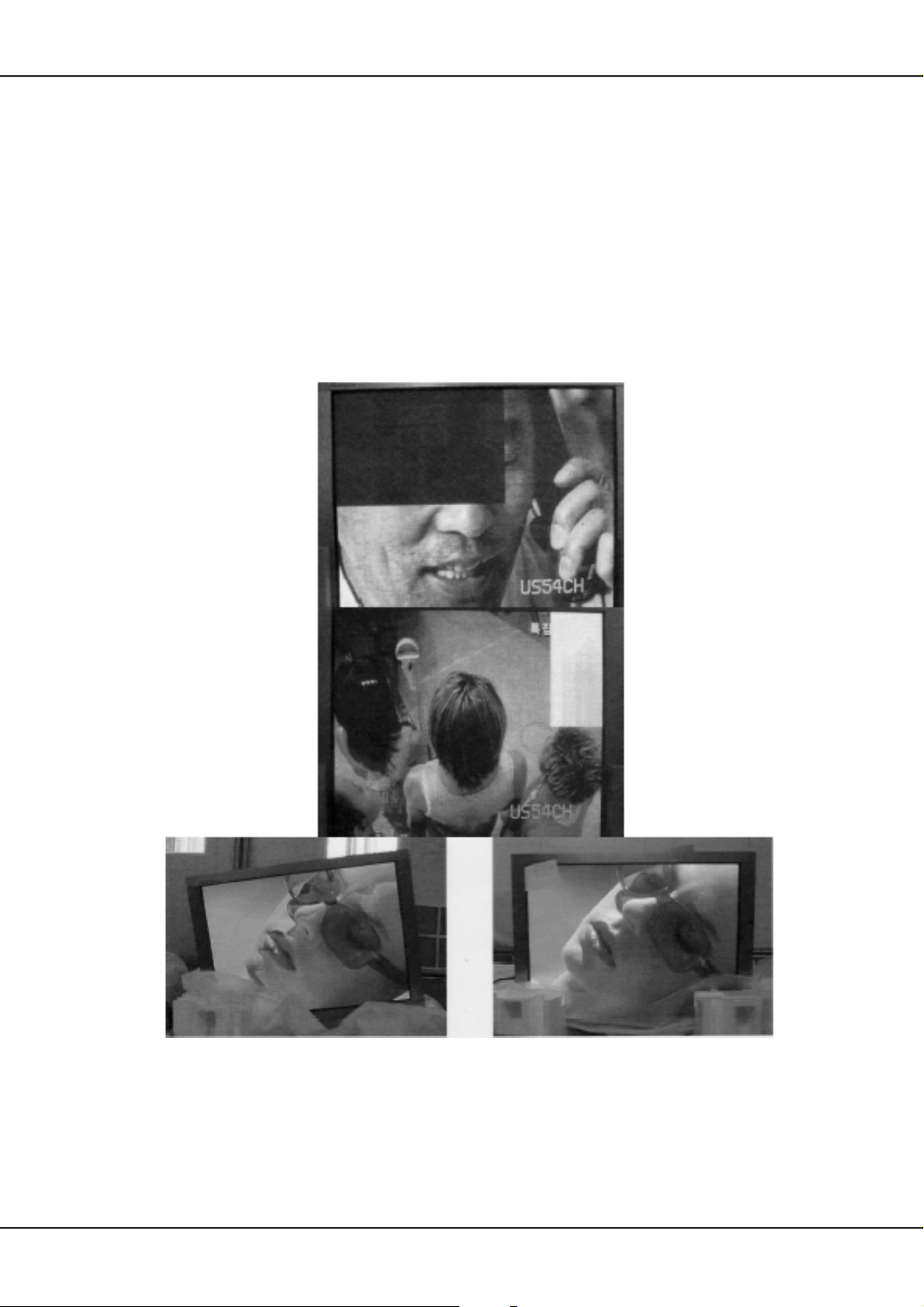
Following examples are typical panel faults. It is assumed that whenever a row or column is missing comletely
or partly, the problem is caused by a problem in the plasma electronics and not by external electronics.
Abnormal Normal
Technical Manual 21
Page 22
Plasma Display
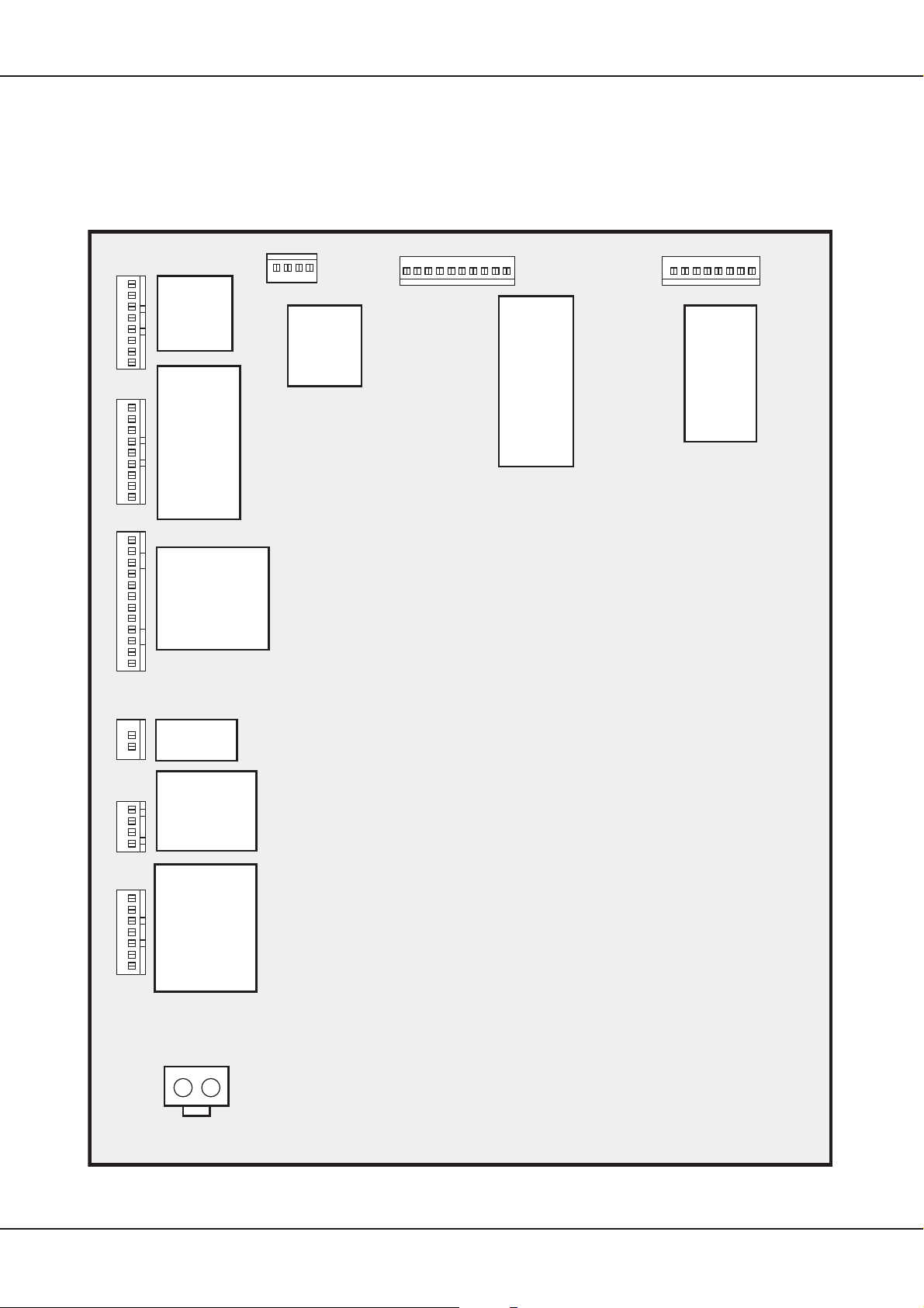
9.3 Power Supply Unit (PSU)
To discover any problems of the plasma panel, it is most simple to check the voltages on the PSU. Please
consider that not all voltages are present in case of failure, as the PSU is dependent of a handshake voltage
from the panel
Following please find the schematic drawing of the PSU with the corresponding connectors.
(see chapter 7. on page 15).
CN808
1
2
3
4
5
6
7
8
CN804
1
2
3
4
5
6
7
8
9
CN803
1
2
3
4
5
6
7
8
9
10
11
12
#1 ~ #4
: +5Vctrl
#5 ~ #8
: GND
#1 : 9Vsc
#2 : 9Vsc
#3 : GND
#4 : 5Vsc
#5 : 5Vsc
#6 : 5Vsc
#7 : GND
#8 : GND
#9 : GND
#1 ~ # 3 : 5Vsc
#4 ~#6 : GND
#7, #8 : 12Vsc
#9, #10 : GND
#11, #12 : NC
CN805
#1 ~ #2
: GND
#3 ~ #4
: +5Vctrl
10 9 8 7 6 5 4 3 2 1 8 7 6 5 4 3 2 1
CN806
#1 : Vs
#2 : Vs
#3 : Vs
#4 : NC
#5 : GND
#6 : GND
#7 : GND
#8 : GND
#9 : Va
#10 : Va
#1 : Vs
#2 : Vs
#3 : NC
#4 : GND
#5 : GND
#6 : Va
#7 : GND
#8 : #5V
CN807
CN809
1
2
CN802
1
2
3
4
CN801
1
2
3
4
5
6
7
#1 : 9Vsc
#2 : GND
#1 ~ #2
: 30V or 24V
#3 ~ #4
: GND
#1 : ACD
#2 : RLY ON
#3 : 5Vst_by
#4 : GND
#4 :Vs On
#6 : 5VD
#7 : NC
CN01
12
Form inlet
22 Technical Manual
Page 23
LVDS-Interface-Board
10. LVDS-Interface-Board
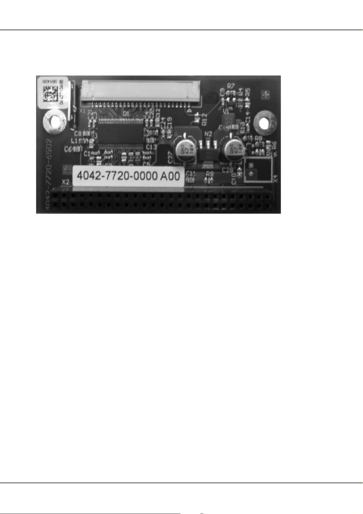
The L VTTL signal, which is present at the output of the A V3 electronics, is generated into a LVDS signal, which
is necessary for operating the plasma, on the L VDS—Interface—Board (L VDS= Low Voltage Dif ferential Signal).
The board is mounted fix to the AV3 via connector X2, the changed signal (LVTTL to LVDS) is routed from X1
directly to the logic board of the plasma. The supply of the L VDS—T ransmitter IC is also solved via X2 (Pin 15
—18 = +5V; Pin 1, 2, 19, 20, 29, 30, 39, 40, 49, 50 = GND)
Technical Manual 23
Page 24
Exploded Drawing
11. Exploded Drawing
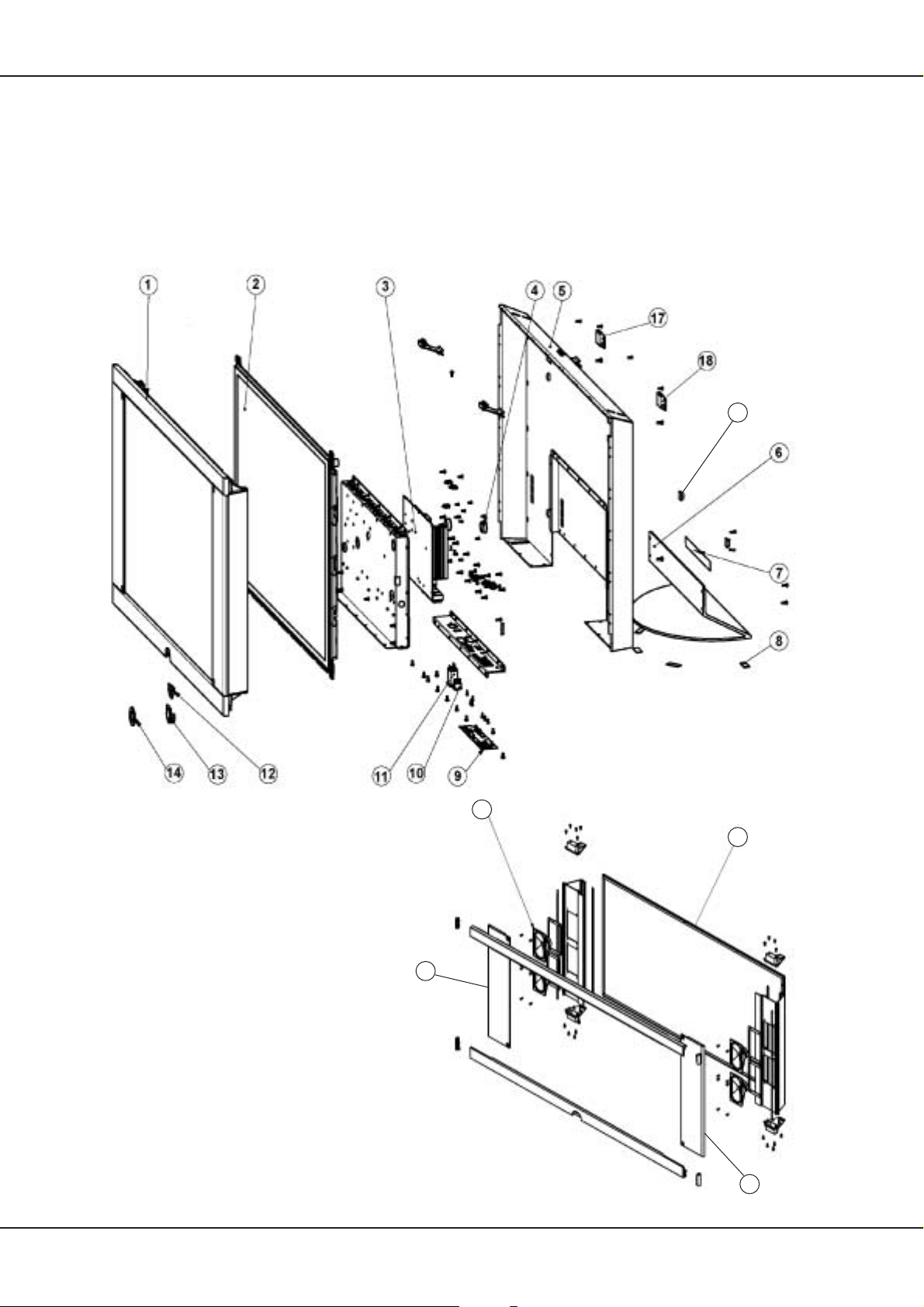
Following you will find the exploded drawing of the device and, for clearness reasons separately, the exploded
view of the front bezel. The mentioned numbers lead to the corresponding position in the spare parts list.
19
20
15
16
20
24 Technical Manual
Page 25
Spare Parts List
12. Spare Parts List
CONCEPT L 42 Art.-Nr. 64403x60
Pos.Nr. Bestell-Bezeichnung Description Bestell-Nr.
ItemN°. List Part N°.
BAUGRUPPEN UNITS
2 PLASMA-DISPLAY 42 ZOLL CONCEPT 42 L4200 .......PLASMA-DISPLAY 42 ZOLL ................................ 345-90432.900
3 SIGNAL BOARD AV3 PLUS L ........................................SIGNAL BOARD AV3 PLUS L .............................. 396-90432.901
12 IR-EMPFAENGER KPL. CONCEPT 42.......................... IR SENSOR CPL. CONCEP 42 ............................ 396-90432.903
U 0103 LVDS INTERFACE BOARD ............................................ LVDS INTERFACE BOARD.................................. 396-90432.902
DRUCKSACHEN OPERATING INSTRUCTIONS
801 BAN -D-I CONCEPT L 42 ALS PDF FILE.............. OIN -D-I CONCEPT L 42 ...................................... 233-32241
801 BAN -E-GB CONCEPT L 42 ALS PDF FILE .............. OIN -E-GB CONCEPT L 42 .................................. 233-32241.010
801 BAN -NL-F CONCEPT L 42 ALS PDF FILE.............. OIN -NL-F CONCEPT L 42 ................................... 233-32241.020
GERÄTEBEIPACK SET SUPPLEMENT
900 RC4 PLATIN .................................................................... RC4 PLATINUM .................................................... 263-89800.A00
N 0811 VERBINDUNGSKABEL 140MM HF/HF .......................... CONNECTING CABLE 140M ............................... 169-90432.919
VERPACKUNGSMATERIAL PACKING MATERIAL
J 0802 VERPACKUNGSKARTON CONCEPT 42 ......................PACKING CASE CONCEP ................................... 245-90432.905
J 0803 VERPACKUNGSECKE CONCEPT 42 OBEN 2 ST. ......PROTECTIVE PACKING TOP 2 PIECE............... 256-90432.906
J 0803 VERPACKUNGSECKE CONCEPT 42 UNTEN 2 ST..... PROTECTIVE PACKING BOT 2 PIECE............... 256-90432.907
VERBINDUNGSLEITUNG CONNECTING CABLES
N 0300 NETZKABEL GRAU 2,5M STECKBAR .......................... POWER CORD ...................................................... 170-90432.918
GEHÄUSETEILE CABINET MOUNTING
1 FRONTRAHMEN PLATIN CONCEPT L 42.................... FRONT FRAME PLATINUM ................................. 778-90432.916
1 FRONTRAHMEN PLATIN CONCEPT L 42.................... FRONT FRAME ANTHRACITE ............................ 786-90432.911
5 RUECKWAND CONCEPT L 42 ......................................BACKCOVER CONCEPT ..................................... 775-90432.909
6 TISCHFUSS PLATIN CONCEPT L 42 ............................ TABLE STAND PLATINUM................................... 484-90432.914
6 TISCHFUSS PLATIN CONCEPT L 42 ............................ TABLE STAND ANTHRACITE.............................. 484-90432.915
8 FILZGLEITER FELT ........................................................ STRIP .................................................................... 414-90432.935
13 IR-GEHÄUSE...................................................................IR CABINET ........................................................... 396-90432.903
14 BLENDE (DECORRING) CONCEPT 42 ......................... COVER (DECORRING) CON ............................... 778-90432.916
16 FRONTSCHEIBE CONCEPT 42..................................... FRONT PANE CONCEPT ..................................... 666-90432.904
17 WANDHALTER LINKS CONCEPT 42 ............................ WALL MOUNT BRACKET LEFT........................... 786-90432.912
18 WANDHALTER RECHTS CONCEPT 42........................ WALL MOUNT BRACKET RIGHT ........................ 786-90432.913
19
20 LAUTSPRECHERGITTER .............................................. SPEAKER GRILLE PLATINUM ............................ 708-90432.938
20 LAUTSPRECHERGITTER .............................................. SPEAKER GRILLE ANTHRACITE ....................... 708-90432.939
15 LAUTSPRECHER 4 OHM 10W 4 STÜCK ......................LOUDSPEAKER 4 OHM 10W 4 PIECE ............... 272-90432.908
10 NETZSCHALTER SCHWARZ......................................... POWER SWITCH BLACK..................................... 471-90432.920
N 0001 KABELBAUM 2-POL. 300MM BL/BN ............................. CABLE HARNESS 2-POL 300MM ........................ 171-90432.929
N 0002
N 0003 KABELBAUM 1-POL. 100MM BN ................................... CABLE HARNESS 1-POL 100MM........................ 171-90432.927
N 0004 KABELBAUM 1-POL. 100MM BL .................................... CABLE HARNESS 1-POL 100MM........................ 171-90432.928
N 0008 KABELBAUM 7-POL. 650MM AV3 CN8 <=> IR X1 ....... CABLE HARNESS 7-POL 650MM........................ 171-90432.931
N 0009 KABELBAUM 1-POL. 150MM SZL .................................CABLE HARNESS 1-POL 150MM........................ 171-90432.926
N 0011
N 0013
N 0019
N 0020
N 0024
N 0025
N 0029
N 0031 KABELBAUM 300MM LVDS X1 <=> PDP P31 .............. CABLE HARNESS 300MM ................................... 171-90432.924
N 0810 VIDEOKABEL 2000MM VGA/DVI ................................... VIDEOCABLE 2000MM......................................... 169-90432.925
ABSTANDSHALTER SELBSTKLEBEND F. RW. B. WANDM
LAUTSPRECHER SPEAKERS
SCHALTER SWITCHES
SPEZIALTEILE SPECIAL PARTS
KABELBAUM 2-POL. 100MM BL/BN PSU CN02 <=>PSU CN03
KABELBAUM 4-POL. 300MM PSU CN802<=>AV3 CN11
KABELBAUM 6-POL. 200MM PSU CN803<=>AV3 CN13
KABELBAUM 7-POL. 300MM PSU CN801<=>AV3 CN19
KABELBAUM 2-POL. SW/RT LAUTSPRECHER ANSCHL
KABELBAUM 1-POL. SW LAUTSPRECHER VERBIND
KABELBAUM 1-POL. SW LAUTSPRECHER VERBIND.
KABELBAUM 2-POL. SW/WS LAUTSPRECHER ANSCHL. ..
. SPACER, ADH. ..................................................... 602-90432.936
. CABLE HARNESS 2-POL 100MM ........................ 171-90432.930
... CABLE HARNESS 4-POL 300MM ........................ 171-90432.921
... CABLE HARNESS 6-POL 200MM ........................ 171-90432.922
... CABLE HARNESS 7-POL 300MM ........................ 171-90432.923
.... CABLE HARNESS 2-POL ..................................... 171-90432.932
.... CABLE HARNESS 1-POL..................................... 171-90432.934
... CABLE HARNESS 1-POL ..................................... 171-90432.934
CABLE HARNESS 2-POL ..................................... 171-90432.933
Technical Manual 25
Page 26

Änderungen vorbehalten
Subject to modification
Modification réserves
Con riserva di modifiche
Reservado el derecho a introducir modificaciones
Wijzigingen voorbehouden
Page 27
Serviceanleitung
L 4200
230-90430.996
Concept L 42
Platin
Art.-Nr. 64403A60
Concept L 42
Anthrazit
Art.-Nr. 64403D60
Page 28

Inhaltsverzeichnis
1. Einleitung ....................................................................................................................3
2. Serviceadresse ...........................................................................................................3
3. Technische Daten ...................................................................................................... 4
4. Service-Hinweise ........................................................................................................7
4.1 Transport ................................................................................................................7
4.2 Reinigung ...............................................................................................................7
4.3 Testbilder ................................................................................................................7
4.4 Massebänder..........................................................................................................7
4.5 OSD-Einblenddauer ...............................................................................................7
4.6 Reset ......................................................................................................................7
4.7 Werkseinstellungen ................................................................................................7
4.8 General Reset ........................................................................................................7
4.9 Übertemperatur-Abschaltung .................................................................................7
4.10 Software-Update...................................................................................................8
4.1 1 Typische Fehler ....................................................................................................8
4.12 Flachbildschirmstecker.........................................................................................9
5. Verdrahtungsplan.....................................................................................................10
6. AV3 Signalprocessing..............................................................................................11
6.1 A V3 Blockschaltbild .............................................................................................. 11
6.2 Anschlusspanel.....................................................................................................1 1
6.3 Anschlüsse ........................................................................................................... 11
6.4 Fehlersuche..........................................................................................................12
7. Startsequenz .............................................................................................................15
8. Service OSD ..............................................................................................................16
10.1 Submenüs ..........................................................................................................16
9. Plasma Display .........................................................................................................19
11.1 Rückansicht mit Leiterplatten..............................................................................19
11.2 Schematischer Aufbau........................................................................................19
11.3 Netzteil................................................................................................................22
10. LVDS-Interface-Board ..............................................................................................23
11. Explosionszeichnung...............................................................................................24
12. Ersatzteilliste ............................................................................................................25
2 Technisches Handbuch
Page 29
Einleitung
1. Einleitung
Dieses Handbuch ist ausschliesslich für technisch geschultes Personal bestimmt!
Es ist dazu gedacht, im Falle eines Defektes Reparaturen auf Baugruppenebene durchzuführen.
Reparaturversuche, die auf Bauteilebene gehen oder, auf Grund von fehlendem Fachwissen, Folgesch den
verursachen, führen automatisch zum Verlust jeglicher Garantieansprüche. Der Hersteller behält sich vor , zur
Reparatur eingesandte Geräte dahingehend zu überprüfen.
Sollten Sie telefonische Hilfe benötigen, halten Sie bitte die Identnummer und die Seriennummer des defekten
Gerätes bereit, beides befindet sich auf dem Typenschild auf der Rückseite des Gerätes in der Nähe der
Netzeingangsbuchse.
Im Falle, dass ein defektes Gerät zur Reparatur eingeschickt werden muss, legen Sie bitte eine ausführliche
Fehlerbeschreibung dem Gerät bei, auf der Sie bitte vermerken, wie sich der Fehler äußert und wann er
auftritt (z.B. immer nach dem Einschalten, sporadisch, etc.).
Sollte ein Fehler dennoch in unserer Servicestelle nicht nachvollziehbar sein, werden wir uns umgehend mit
Ihnen in Verbindung setzen. Aus diesem Grund ist es hilfreich, wenn in den Lieferpapieren neben der
Fehlerbeschreibung auch ein technischer Ansprechpartner, m glichst inkl. Telefonnummer, aufgefÜhrt ist.
2. Serviceadresse
Loewe-Service und Logistik
LOEWE OPTA GmbH
Service + Logistik
Zentrale Kronach
96305 Kronach • Postfach 1554
96317 Kronach • Industriestraße 11
Bei Arbeiten am, bzw. im Gerät ist grundsätzlich der
Netzstecker zu ziehen!
Im Gerät finden sich gefährliche Spannungen. Es gelten
die Vorschriften und Sicherheitshinweise gemäß VDE,
sowie zusätzlich die eventuell abweichenden,
landesspezifischen Vorschriften!
ESD-Vorschriften beachten!
Die wichtigsten Rufnummern der Zentrale Kronach:
The most important phone numbers of the Kronach headquarters
Telefon: FAX
Ersatzteilbestellungen: (01 80) 522 1800 (01 80) 522 1806
Status von Reparaturen: (0180) 522 1805 (0 92 61) 99 412
Support TV Röhre: (0180) 522 1801 (0 92 61) 99 730
Support Video/DVD: (0180) 522 1802 (0 92 61) 99 730
Support Telekommunikation: (0180) 522 1803 (0 92 61) 99 730
Support HiFi: (0180) 522 1804 (0 92 61) 99 730
Support TV Plasma, LCD, Rückprojektion: (01 80) 522 1807 (0 92 61) 99 730
Hinweis!
Ersatzteilbestellung nur über Service + Logistik / Zentrale 96317 Kronach
Technisches Handbuch 3
Page 30

Technische Daten
3. Technische Daten
CONCEPT L 42
Display:
Modell: PDP42V6####
Display Typ: AC—PDP, V6
Diagonale: 107 cm (42”)
Aktiver Bildschirmbereich (h x b): 920,1 mm x 518,4 mm
Seitenverhältnis: 16:9
Physikalische Auflösung in Pixel: 852 x 480
Anzahl darstellbarer Farben: 16,77 Mio.
Maximale Helligkeit: typ. 1000 cd / m2 (white peak @ 4% display load)
Maximales Kontrastverhältnis: typ. 3000:1 (dark room, white peak @ 4% display load)
Blickwinkel (O/U, L/R): 800/800 , 800/800, typisch
Begrenzung Leistungsaufnahme: APC (Automatic Power Control)
Farbtemperatur: 9500K (bei 20% grau) Kennlinie gemäß Hersteller—Spec,
kein 2—Punktabgleich möglich.
Oben genannte Werte gelten nach ca. 20 min. Betrieb und 25°C Umgebungstemperatur.
Vorsatzscheibe:
Art: Sicherheitsglas inkl. Mesh
Transmission: 48% +/— 5%
Stromversorgung:
Netzspannung: 115 — 230V ~ +/— 10%
Netzfrequenz: 50/60 Hz +/— 6%
Leistungsaufnahme: 5W typ. in Standby, ca. 350W in Betrieb
Einschaltstrom: 40A max.
Ein— / Ausgänge:
Bezeichnung Eingang / Ausgang Signal
Cinch / Cinch: disabled keine Funktion
Cinch / Cinch: Ausgang Audio Subwoofer Line out / n.c.
Cinch / Cinch: Ausgang Audio Stereo Line out
Cinch / Cinch: Eingang Audio Stereo für CVBS / YUV
Cinch / Cinch: Eingang Audio Stereo für PC
Cinch / Cinch: Eingang Audio Stereo für Y/C (S—Video)
DVI—I: Eingang PC Anschluss an DVI—/ VGA—Signalquelle
IEC: Eingang RF Antennensignal terrestrisch oder Kabel
IEC: Ausgang RF Mit Überbrückungskabel verbunden mit:
IEC: Eingang RF
D—Sub 9pol: Eingang / Ausgang PC RS232 für Softwareupdate
3x Cinch: Eingang Video YUV, kombiniert mit CVBS
Euro AV: Eingang Video FBAS , RGB, Audio L/R
Ausgang Video FBAS , Audio L/R
Euro AV: Eingang Video FBAS , Audio L/R
Ausgang Video FBAS , Audio L/R
Eingangssignale im PC Modus
Horizontaler Frequenzbereich: 30kHz ... 80kHz
Vertikaler Frequenzbereich: 50Hz ... 90Hz
Pixel Clock Frequenz: max. 140MHz RGB, max. 110MHz DVI
Signalpegel, nominal: 0,7Vp—p +/— 3dB bei 75 Ohm
Synchronisation: SoG, Composite Sync, H— und V—Sync, getrennt
Sync. Polarität: positiv und negativ
Sync. Pegel: TTL, Belastung >1kOhm +/— 10%, bei SoG 0,3Vp—p +/— 0,015V,
negativ
VESA DDC Standard: 2B
Jitter: <6% @ 140MHz
Eingangswiderstand: 75 Ohm +/— 10% (0 ... 200MHz)
Unterscheidungsgrenze Timings: +/— 2% (horizontal, vertikal)
Übergangszeit zw. 2 Timings: < 5sec
4 Technisches Handbuch
Page 31

Technische Daten
Darstellbare Auflösung im PC Modus (analog)
170 vorprogrammierte Timings, z.B.
DOS 640 x 480 60Hz
DOS 720 x 400 70Hz
VGA 640 x 480 50Hz bis 90Hz
SVGA 800 x 600 50Hz bis 90Hz
XGA 1024 x 768 50Hz bis 90Hz
Formatdarstellung im PC Modus (analog)
1 1:1
2 Formatfüllend
3 Benutzer Zoom (40% bis 140%)
4Vollbild
Eingangssignal im PC Modus (digital)
Standard: DVI 1.0
Pixel Clock Frequenz: max. 110MHz
Eingangssignale im Video Modus
Standards: PAL: B/G, DK, I, M, N
SECAM: B/G, DK/K1, L/L’
NTSC: M4, B/G4, D/K4, I, NTSC—V (4,43)
Signaltypen: YUV, CVBS, Y/C, RGB
FBAS Signalpegel, nominal: 1Vp—p +/— 3% bei 75 Ohm
RGB Signalpegel, nominal: 0,7Vp—p +/— 3% bei 75 Ohm
Y—Signalpegel, nominal: 1Vp—p +/— 3% bei 75 Ohm
U—Signalpegel, nominal: 0,7Vp—p +/— 3% bei 75 Ohm
V—Signalpegel, nominal: 0,7Vp—p +/— 3% bei 75 Ohm
C (PAL) Signalpegel, nominal: 0,3Vp—p +/— 3% bei 75 Ohm Farbsynchronsignal
C (SECAM) Signalpegel, nominal: 0,286Vp—p +/— 3% bei 75 Ohm Farbsynchronsignal
Automatische Formaterkennung: WSS, BLD
CVBS Prozessing: Digitales Kammfilter
Synchronisation: Analog und automatische Syncerkennung
Syncarten: Composite, SoG
Syncpegel: 0,3Vss +/— 3dB /75 Ohm
Formatdarstellung im Video Modus
1 4:3
2 16:9
3 Zoom (130%)
4 Benutzer Zoom (40% bis 140%)
5Vollbild
6 Panorama Zoom —> Cinema
7Auto
Darstellbare Standards im RF Modus
FBAS Signale: PAL: B/G, DK, I
SECAM: B/G, DK/K1, L/L’
RF Empfangsbereich: 47MHz bis 861MHz (VHF / UHF / Hyperband)
Sendereinstellung im RF Modus
Sendereinstellung: Automatischer Sendersuchlauf
Speicherung und manuelle Abstimmung
Anzahl Programmspeicherplätze: 99
Sendersortierung: ja
Videotext
Videotext: TOP/FLOF, Level 2.5
Anzahl der gespeicherten Seiten: 2100
VPS: nein
EPG: nein
Audio Signale
Audio Pegel Stereo Eingänge: 1Vrms
Audio Pegel Stereo Line Ausgang: 1Vrms +6dB / —20dB einstellbar über OSD
Frequenzgang (Line in / Line out): 20Hz bis 20kHz
Technisches Handbuch 5
Page 32
Technische Daten
Audio Einstellmöglichkeiten
Equalizer: ja, 5 Regler
Höhen, Tiefen: nicht vorhanden
Lautsprecher
Anzahl: 2 pro Seite
Frequenzgang: 100Hz — 20kHz, —3dB
Leistung: > 5W Nennleistung / Lautsprecher
Impedanz: 4 Ohm /Lsp, Serienschaltung auf 8 Ohm
Geräteabmessungen und Gewicht
Abmessungen mit und ohne Fuß:
116,7
62,8
Tiefe 9,4
Gewicht ohne Fuß: ca. 30kg
Gewicht inkl. Fuß: ca. 35kg
Pixelfehler
Zulässige Pixelfehler: Gemäß Hersteller—Spezifikation für das eingesetzte PDP
116,7
70,7
Tiefe 21,8
(6 dunkle in A+B, 2 helle in B)
A-Zone
25% of
Display Area
B-Zone 75% of Display Area
6 Technisches Handbuch
Page 33

Service Hinweise
4. Service-Hinweise
4.1 Transport
Die Displays dürfen nur senkrecht transportiert werden! Für den Transport ist auf eine sichere Verpackung zu
achten, hierfür eignet sich am besten die Originalverpackung, die Sie bei Ihrer zuständigen LOEWE—
Servicestelle bestellen können
4.2 Reinigung
Die Oberflächenreinigung erfolgt am besten mit einem feuchten, fusselfreien Tuch. Als Reiniger empfiehlt der
Hersteller umweltfreundlichen Glasreiniger.
Die Reinigung der Belüftungsöffnungen erfolgt am besten mit einem tragbaren Staubsauger (Tischstaubsauger),
von einer Reinigung mit Pressluft wird abgeraten, da vorhandener Schmutz dadurch leicht in das Gerät gelangt.
4.3 Testbilder
Bei Verwendung der AV—Elektronik stehen im Service—Menü Testbilder zur Verfügung
8.1 auf Seite 16)
4.4 Massebänder
Massebänder, die das Display mit dem Geh userahmen verbinden, müssen nach der Reparatur wieder
angebracht werden, damit die EMV—Vorschriften eingehalten werden. Bänder, die beim Entfernen zerrissen
sind, müssen ersetzt werden.
(siehe Kapitel 2. auf Seite 3).
(siehe auch Kapitel
4.5 OSD—Einblenddauer
Für den Service ist es hilfreich, die Anzeigedauer der Menüs auf ”AUS” zu stellen. Die Menüs werden dann
nicht mehr automatisch ausgeblendet
(siehe auch Benutzerhandbuch)
4.6 Reset
Bei Fehlfunktionen oder wenn sich das Gerät ”aufgehängt” hat (keine Funktion über IR—Fernbedienung mehr
möglich), Gerät über Netzschalter ausschalten — 30 Sekunden warten (bis alle Elektrolyt—Kondensatoren
entladen sind) — Gerät wieder einschalten.
4.7 Werkseinstellungen
Im OSD—Menü unter ”Einstellung” finden Sie die Funktion ”Aufruf Werkseinstellungen”. Alle Einstellungen
werden zurückgesetzt, der Senderspeicher wird nicht gelöscht
(siehe auch Benutzerhandbuch).
4.8 General Reset
Im Service—Menü (Aufruf über ”8640”,
”Alles zurücksetzen” ein kompletter Reset durchgeführt werden.
ACHTUNG: Hier werden auch der Betriebsstundenzähler sowie der Senderspeicher gelöscht!
siehe auch Kapitel 8.1.2 auf Seite 17)
kann unter dem Menüpunkt
4.9 Übertemperatur—Abschaltung
”WARNING” wird eingeblendet, wenn die Temperatur an der A V3 Elektronik 60°C (Temperatur 1) überschreitet.
Das Gerät wird in Standby geschaltet, die rote LED leuchtet, wenn die Temperatur an der A V3 Elektronik 65°C
(Temperatur 2) überschreitet. Das Gerät kann über die Fernbedienung wieder eingeschaltet werden.
Das Gerätwird in Standby geschaltet, die rote LED blinkt, wenn die Temperatur an der AV3 Elektronik 70°C
(Temperatur 3) überschreitet. Das Gerät kann über die Fernbedienung nicht mehr eingeschaltet werden.
Sinkt die Temperatur wieder unter 60°C, hört die LED auf zu blinken, das Gerät kann wieder eingeschaltet
werden
(siehe auch Kapitel 8.1.4 auf Seite 17)
.
Technisches Handbuch 7
Page 34

Service Hinweise
4.10 Software—Update
Benötigt wird:
— Update—Programm ”FlashUpgrader.exe” (für Windows 98 und Windows ME) oder ”FlashUpgraderNT.exe”
(für Windows NT4.0, Windows 2000 sowie Windows XP). Unter Windows 95 ist kein Update möglich.
— aktuelle Software (sowohl das Update Programm als auch die aktuelle Software für Ihr Gerät erhalten Sie
als zip—file bei Ihrer LOEWE—Servicestelle,
— Null—Modem Kabel (serielles Datenkabel (RS232) mit beidseitigem 9 poligen weiblichen Steckverbinder.
Das Kabel muss gekreuzt verdrahtet sein).
Update:
— Update—Programm und neue Software in ein neues Verzeichnis entpacken.
— Gerät abschalten (Netzschalter)
— Update—Programm starten
— Über ”Choose...” die Datei ” *.inf” im neu angelegten Verzeichnis mit den Firmwaredaten auswählen
— ”Connection” auf ”serial” einstellen, benutzten Com—Port sowie die Baud—Rate einstellen (empfohlen
wird 115200)
— Alle weiteren Optionen verbleiben auf ”Default”—Position
— ”Flash” anklicken, das Programm wird in Bereitschaft geschaltet
— Gerät über Netzschalter einschalten. Das Programm startet automatisch, der Fortschritt wird über eine
Balken—anzeige mitgeteilt. Je nach gewählter Baud—Rate dauert das Update ca. 3—6 Minuten.
(siehe Kapitel 2. auf 4
)
4.11 Typische Fehler
Sollte ein Fehler am Gerät auftreten, ist es ratsam, vor Öffnen des Gerätes die externe Verkabelung zu
überprüfen:
— Ist die Netzspannung vorhanden?
— Sind die entsprechenden Signalkabel richtig angeschlossen?
— Liefern die externen Geräte ein Signal?
— Ist die richtige Eingangsquelle ausgewählt?
Auch nach dem Öffnen des Gerätes ist es sinnvoll, die interne Verkabelung und die Steckverbinder zu
überprüfen, um eventuelle Wackelkontakte von vornherein ausschließen zu können.
4.11.1 Kein Bild (bei allen Betriebsarten)
— Ein— und Ausgänge des Netzteils überprüfen
(siehe Kapitel 9.3 auf Seite 22)
4.11.2 Gerät lässt sich nicht einschalten (bleibt in StandBy)
— Fernbedienung überprüfen (Batterien!)
— Software neu installieren
— A V3—Elektronik überprüfen
(siehe Kapitel 4.10 auf 8)
(siehe Kapitel 6.4 auf 12)
4.11.3 Spalten— / Zeilenfehler, Zeilen oder Spalten fehlen
— Display überprüfen
(siehe Kapitel 9. auf Seite 19)
4.11.4 Pixelfehler
Technologisch bedingt kann es sowohl bei TFT—LCDs als auch bei Plasma—Displays zu Ausfüllen einzelner
Pixel oder Subpixel kommen. Sofern sich die Anzahl der Pixelfehler innerhalb der in der Spezifikation
angegebenen Grenzen befinden, liegt kein Gerätedefekt vor
(siehe ”Pixelfehler”, Kapitel 3.auf Seite 6)
.
4.11.5 Farben fehlen
— Datenkabel prüfen
— A V3 überprüfen
— Display überprüfen
(siehe Kapitel 6. auf Seite 11)
(siehe Kapitel 6.4 auf 12)
(siehe Kapitel 9. auf 19)
4.11.6 Suchlauf funktioniert nicht / nicht richtig
— A V3 überprüfen
8 Technisches Handbuch
(siehe Kapitel 6.4 auf 12)
Page 35
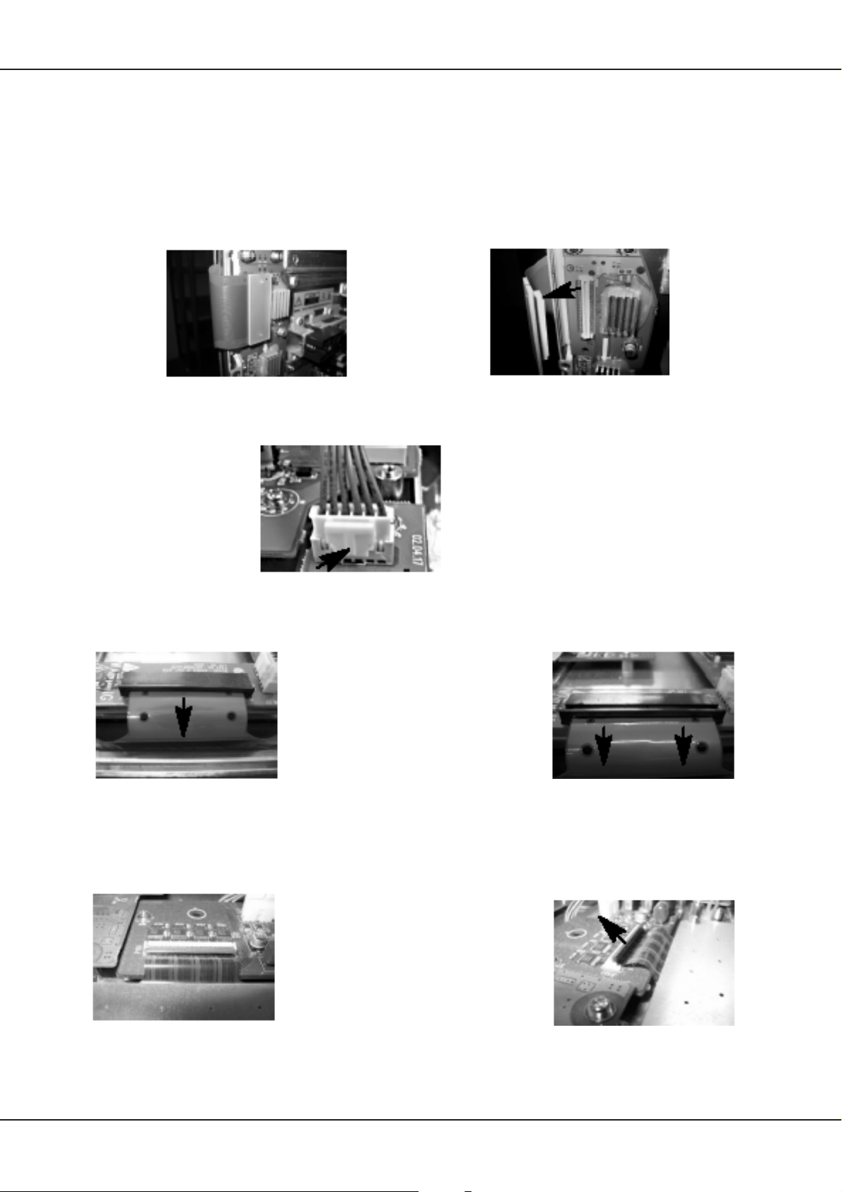
Service Hinweise
4.12 Flachbildschirmstecker
Sollte auf einem TFT—LCD—Panel oder Plasma—Panel eine Überprüfung oder Reparatur notwendig sein,
ist es unumgänglich, den einen oder anderen Steckverbinder zu lösen. Teilweise gestaltet sich dies jedoch
etwas kompliziert, ein Lösen mit Gewalt kann im schlimmsten Fall einen T otalschaden des Panels verursachen.
Nachfolgend die gängigsten Steckverbindungen und wie sie zu lösen sind:
nach oben anheben
vor dem Abziehen durch Pressen entriegeln
zum Entriegeln in Pfeilrichtung ziehen
auf Rastnasen achten!
zum Entriegeln in Pfeilrichtung klappen
Technisches Handbuch 9
Page 36
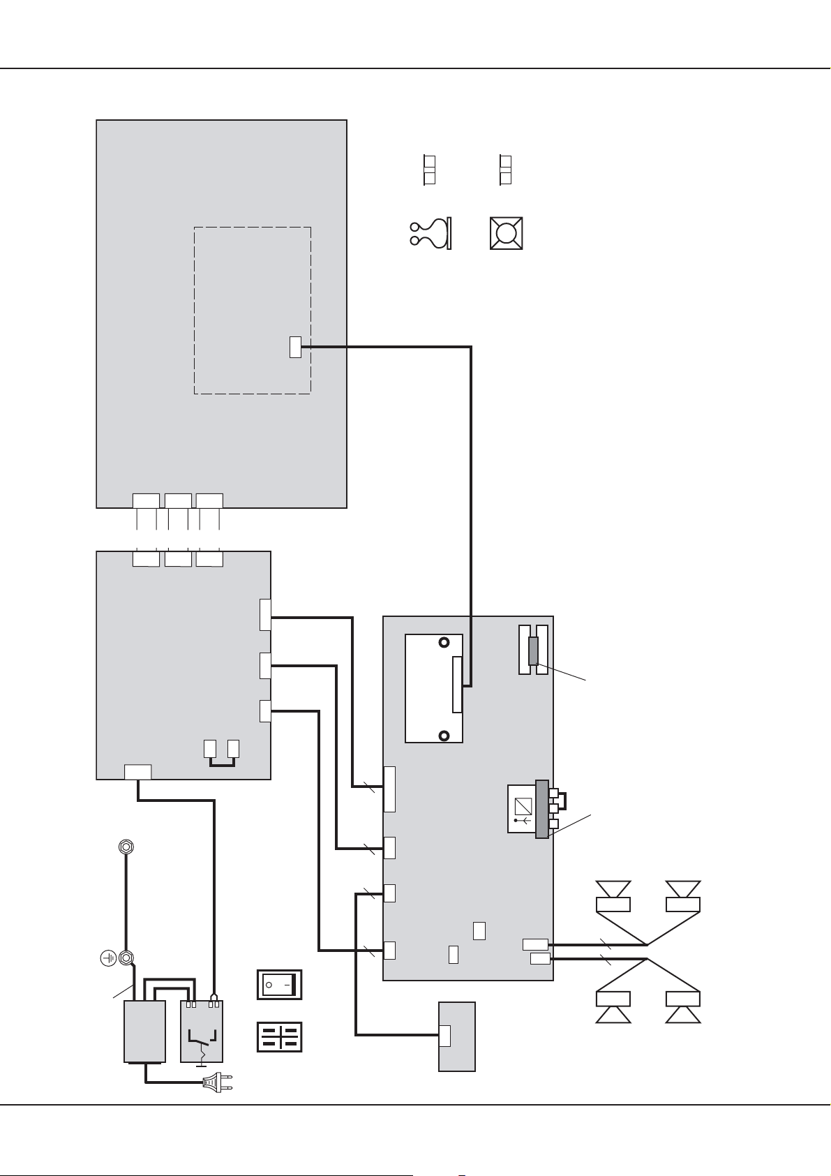
5. Verdrahtungsplan
P1031
90432.900
LG Electronics
42 ” Plasma Display
PDP 42V6.....(LG KK)
P2008P2005P3001
4 pol
4 pin
CN805CN806CN807
10 pol
10 pin
Logic Board
8 pol
1 GND 13 GND
2 RA- 14 GND
3 RA+ 15-18 n.c.
8 pin
Wiring, premounted
Verkabelung, vormontiert
4 RB- 19 GND
5 RB+ 20-25 n.c.
6 GND 26 GND
7 RC- 27 DISPEN
8 RC+ 28 SDATA
9 RCLK- 29 SCLK
10 RCLK+ 30 SLE
11 RD- 31 GND
12 RD+
P31
Connector
Signal Input
4 X
00
Kantenschutz
? X
Driller
300lg
90432.924
? X
2 X
00
Kantenschutz
Klebeschellen
Netzteil Bestandteil des PDP
Power Supply Unit (PSU) Part of PDP
Bolzen für Erdung, Zahnscheibe verwenden
Earth over bolted assembly, use a toothed lock washer
L
N
1
2
CON1
roter Sockel
150lg
PE
Part of PDP
Netzeingang
(Bestandteil PDP)
Power Input
Part of (PDP)
90432.918
1 ACD
red socket
100lg
Netzschalter
Power Switch
2 RLY ON
1a
2a
3 +5Vst_by 1,2,3 +5V
4 GND 4,5,6 GND
5 Vs ON 7,8 +12V
CN02
112
Power
6 5VD 9,10 GND
7 n.c. 11,12 n.c.
+5VSB and
Audio
1,2 30V
3,4 GND
CN03
300lg
Ansicht der Netzschalter-Kontakte
230 V~
5V / 12V
PSU control
Power
CN802 CN801 CN803
1a
2a
View on the power switch contacts
90432.921
90432.920
2
Pin Leitung / wire
1a 0921-0204-6501D3
200lg
90432.922
6774
300lg
90432.923
300lg
650lg
1 2215-1146-0001 (braun / brown)
2a 0921-0204-6501E3
2 2215-1146-0001 (blau / blue)
Power +5V/+12V in
Control
CN8
Keyboard
CN11 CN19 CN13
Audio
10 pin
7 pin
7 pin
Power in
X1
90432.902
LVDS-Adapter
1 +5VST
2,4,6 GND
3,5 +5V (VCC)
7 +12V
8 PSSTDBY
9 PSDPMS
1 ACPWCK
2 RLYON
3 5V STBY
4 GND
5 VSon
6 FPVRR
1,7,18 GND
3 LED (rt/rd)
4 LED (grn)
19 +5VST
20 IR Rec
J7
4 pin
1,2 GND
3,4 30V
X1
IR-Receiver
LED grn/rt // grn7rd
X1
1 GND 11RD+ 19 GND
10 FPVRR
7 n.c.
CN2
90432.903
2 DISPEN 12 RB- 20 R3+
3 SLE 13 GND 21 R3-
PIP-Tuner
AV3plusL
Scart 1
4 SCLK 14 RCLK+ 22 GND
5 SDATA 15 RCLK- 23 RA+
6 GND 16 GND 24 RA-
7-9 n.c. 17 RC+ 25 GND
f1
f2
f1
90432.901
L
R
Scart 2
10 GND 18 RC-
CN29
CN20
140lg
90432.919
Folie 12 cm Kontaktblech
LS-L
2
2
4 Speakers 4 Ohm
--
++
++
--
LS-R
90432.908
10 Technisches Handbuch
Page 37
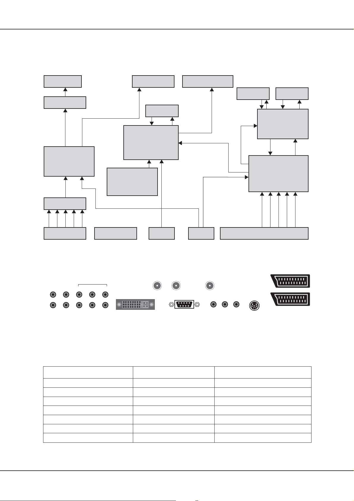
6. AV3 Signalprocessing
6.1 AV3 Blockschaltbild
Speakers Out
Cinch
Audio Amplifier
TDA 7263
Sound Ouput
1x Cinch & 2x Scart
Image Processor
Main CPU
Flash ROM
1 MByte
Display Port 48Bit
AV3 Signalprocessing
SDRAM
2 MByte
Flash ROM
2 MByte
Teletext Engine
SDA 6000
Sound Processor
(ADC/DAC)
MSP 3410G
Audio Matrix
Sound Input
3x Cinch & 2x Scart
VGA/HDTVp In
1x analog & 1x DVI
6.2 Anschlusspanel
NC
LINE
OUT
SUB
LINE
OUT
CVBS/YUV
LINE IN
S-VIDEOPC
PW 181
VGA ADC
& DVI Receiver
AD 9887
PC DVI-I
RS232
DSUB
RF IN
RF OUT
RS232
2x RF-
Tuner
ANTENNA
Video Decoder
& PIP Engine
& Video Matrix
(embedded RAM)
VSP 9417
YUV
Video Input
SCART 2
SCART 1
S-VIDEO
3x Cinch (YUV), 1x MiniDIN, 2x Scart (RGB)
CVBS
6.3 Anschlüsse
Nachfolgend sind die wichtigsten Steckverbinder aufgeführt. Aus Gründen der Übersichtlichkeit sind
nur die Steckverbinder benannt, die auch tatsächlich benutzt sind.
Stecker
CN 1
CN 4
CN 6-C
CN 22
CN 5
CN 3-A
CN 3-B
Technisches Handbuch 11
Pin Bezeichnung
2x Scart, Scart1 auch RGB tauglich
S-Video
CVBS
RS-232
DVI-I
PC Audio in
YC Audio in
Page 38
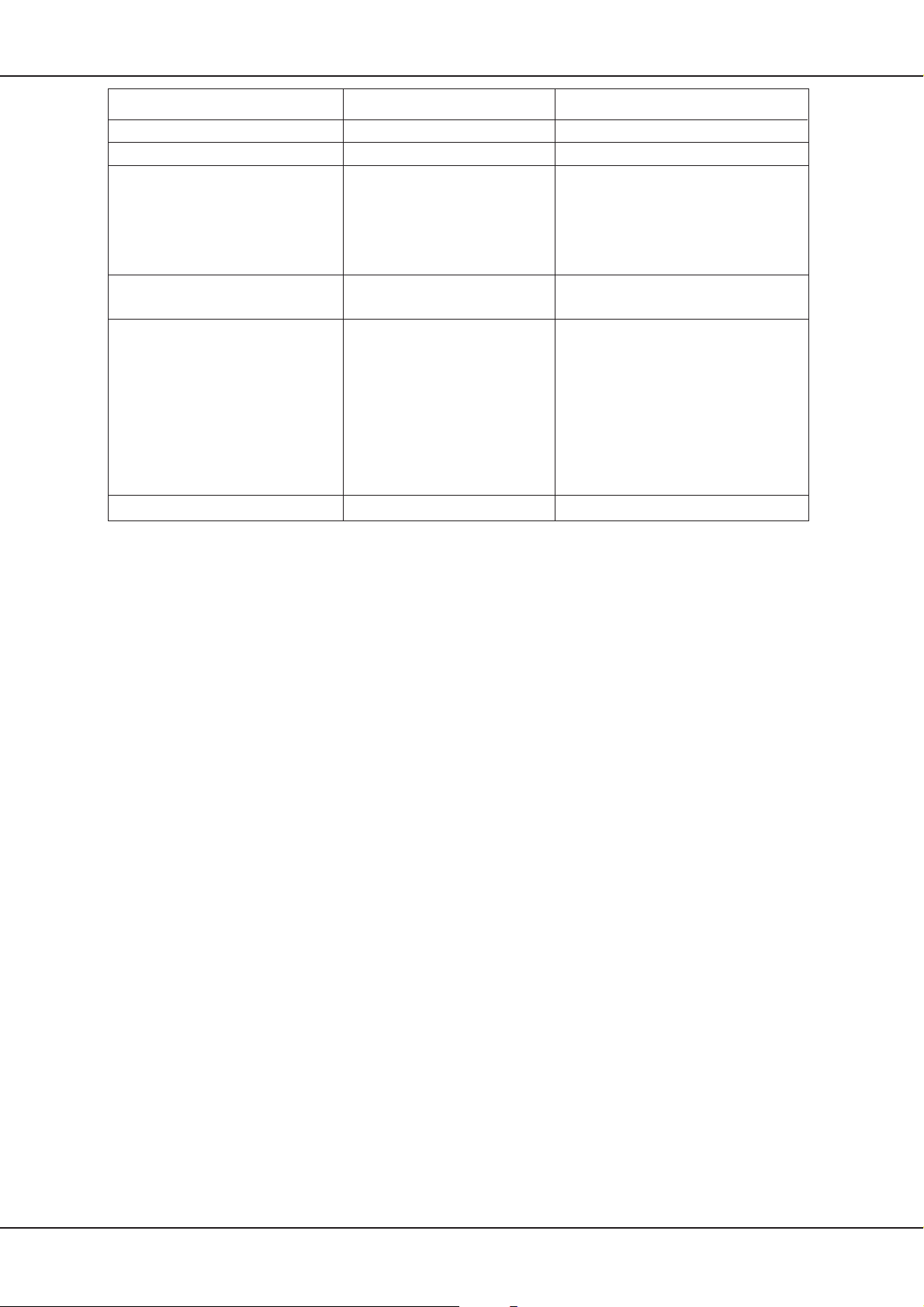
AV3 Signalprocessing
Stecker
CN 15
CN 6 -A/-B/-C
CN 21
CN 11
CN 13
CN 33
Pin Bezeichnung
CVBS/YUV Audio in
YUV
1,5,7
2
3
4
6
1,2
3,4
1
2,4,6
3
5
7
8
9
10
1-50
GRLED (grüne LED)
STBY (start low voltage)
DPMS (start high voltage)
GND
5V Standby
IRRCVR (Sensor)
RDLED (rote LED)
GND
30V Audio
5V Standby
GND
5V
5V
12V
VRR (PD Pready)
Digital Output
6.4 Fehlersuche
6.4.1 Ohne Öffnen des Gerätes
— Analyse Front LEDs
Rote LED trotz Einschalten über die Fernbedienung: Gerät bleibt in Standby, mögliche Fehlerquellen sind
Fernbedienung oder AV3 Elektronik.
Grüne LED, aber kein Bild: Gerät ist aktiv, zeigt aber kein Bild an, mögliche Fehlerquellen sind: falsche
Eingangsquelle ausgewählt oder Panel ist defekt.
Rote und grüne LED: Gerät befindet sich in einem undefinierten Zustand, Fehlerquelle ist dann meistens die
AV3 Elektronik.
— Analyse Bildschirm
Wenn bei schwarzem Bildschirm (es wird kein Bild angezeigt) noch ein leichter Helligkeitsschimmer zu sehen
ist (Blickpunkt mit der Hand abdunkeln), kann man davon ausgehen, dass ein Fehler im Signalweg vorliegt
und nicht am Panel.
— Akustische Analyse (Relais)
Beim Ein— bzw. Ausschalten des Gerätes ist jeweils ein Klicken zu hören. Ist dies nicht vorhanden, liegt der
Fehler in den meisten Fällen auf dem Netzteil.
6.4.2 Bei geöffnetem Gerät
— Überprüfung der Spannungsversorgung (als Messpunkte dienen die Pins der Steckverbinder,
6.3 auf 11).
— Eingrenzung von Fehlern (durch Überprüfung, bzw. Austausch der einzelnen Baugruppen)..
(siehe Kapitel
6.4.3 Problembeseitigung, häufig gestellte Fragen (FAQs)
Verrauschtes Bild im Tuner Mode
— Signalpegel sollte über 68dbµV liegen (typischer Pegel der Kabelbetreiber)
— hoher Rauschpegel auf RF—Signal (schlechtes SNR)
— DNC auf max. einstellen (OSD)
— Rauschpegel wird bei PDPs aufgrund der digitalen Signalverarbeitung deutlich stärker wahrgenommen als
bei 50Hz interlace CRT s oder 50Hz progressive CRTs (8Bit Aufl sung, False Contouring, Dithering, Deinterlacing,
Limitierung des verwendeten PDPs, ...)
Verrauschtes Bild in Video Modes
— hoher Rauschpegel auf Video—Signal (schlechte Quelle)
— DNC auf max. einstellen (OSD)
12 Technisches Handbuch
Page 39

AV3 Signalprocessing
— Rauschpegel wird bei PDPs aufgrund der digitalen Signalverarbeitung deutlich stärker wahrgenommen als
bei 50Hz interlace CRT s oder 50Hz progressive CR T s (8Bit Auflösung, False Contouring, Dithering, Gamma—
Korrektur, Deinterlacing, Limitierung des verwendeten PDPs, ...)
— Nach Möglichkeit die Verwendung von FBAS Signalen vermeiden, besser SCART—RGB oder S—Video
verwenden
Regelmäßige horizontale oder diagonale Streifen im Videobild
— Signalleitungen richtig verlegen (Störemission des PDP)
— Brummschleife (Massepotential—Verschiebung)
Videobild wird nur schwarz/weiß dargestellt
— schwacher Signalpegel bzw. nicht Norm—gerechtes Signal
— nicht unterstütztes Signal (z.B. NTSC über RF)
Beim Sendersuchlauf werden nicht alle Sender mit Sendernamen erkannt bzw. Sendername ist falsch
— Gerät unterstützt kein PDC (...)
— Gerät arbeitet mit interner Sendernamen—T abelle, sollte sich Sendername kurzfristig ändern, so kann dies
zu falschen Angaben führen
Bild ist flau und wenig kontrastreich (Video/VGA)
— die Werkseinstellungen für Kontrast und Helligkeit sind für die meisten Anwendungen optimal, nur in wenigen
Fällen empfiehlt es sich, die Werte zu ändern
— Auch andere Einstellungen können die Bildqualität negativ beeinflussen, deshalb immer zunächst auf die
Werkseinstellungen zurücksetzen (OSD—Menü)
Bild im VGA—Mode unscharf
— es wird empfohlen mit max. 848x480 Auflösung zu arbeiten,
— in seltenen Fällen (schlechte Signalqualität oder ungünstige Bilddarstellung) kann das Autoadjustment
nicht korrekt arbeiten (siehe Operating—Manual); Taste Auto für manuelles Autoadjustment betötigen
— Einstellung Schärfe im Menü Bild an die Signalquelle anpassen
Technisches Handbuch 13
Page 40
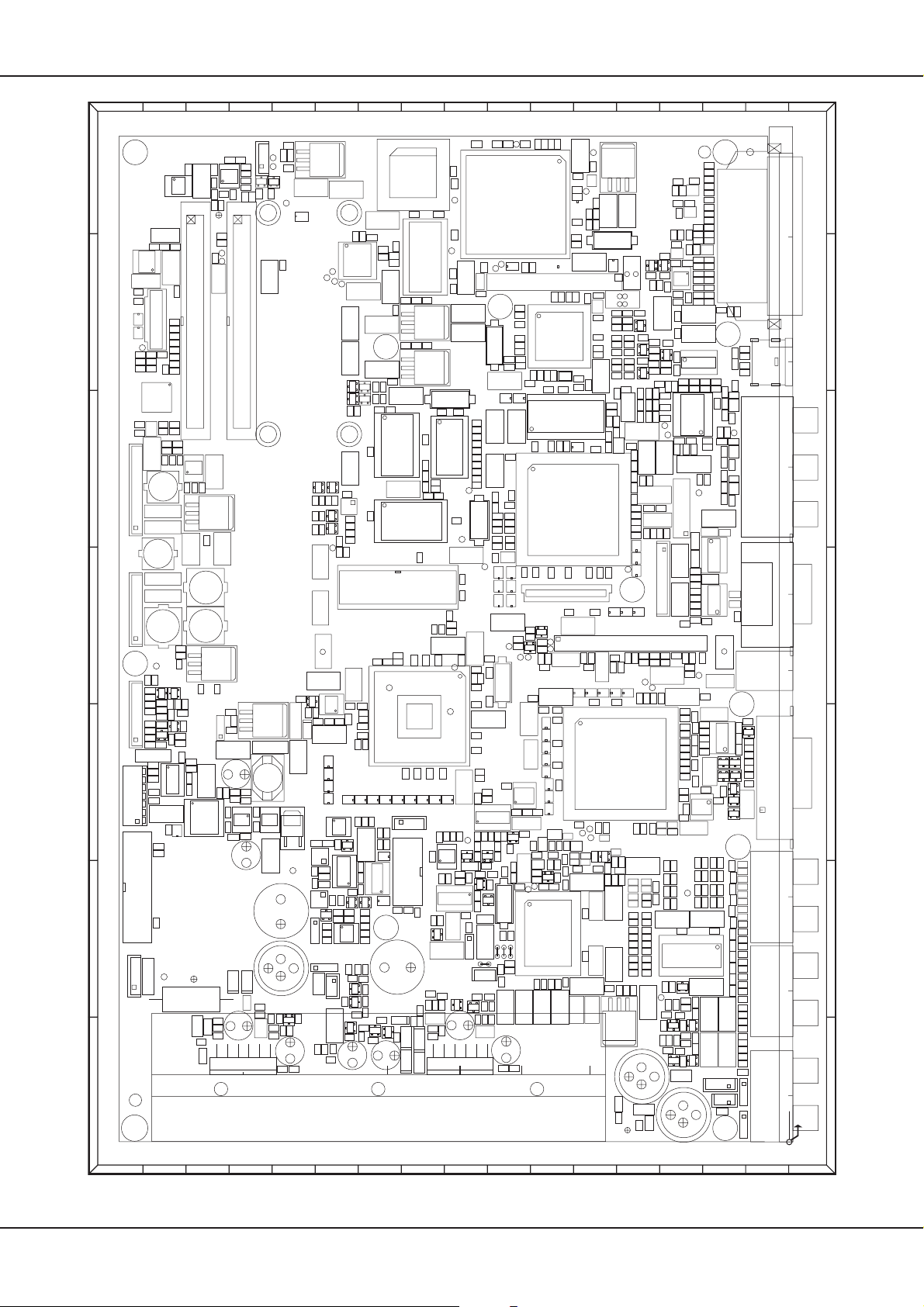
AV3 Signalprocessing
U22
C92
R483 R482R71
C123
C120
R80
R79
+
C513
C521
RN23RN22RN21RN20RN19RN18RN16RN15
+
R94
R90
C110
VR3
VR8
C106 C116
R127
R491
C51
R494
C417
D3
R91
R92
+
C66
RN17
C469
U32
C100
C420
C147
C107C103
TP45
TP44
C230
C148
+
+
X2
U18
C115
+
R358
R449
R164
R362
TP7 TP32
C56
R389
R315
R365
R282
C331
C345
U39
C410
+
C124
R83
U19
C186 C170 C268 C180
+
C155
J3
C184
R147
C87
C146
C121
R106
R105
R104
R103
R102
R101
R100
R99
R449
TP4
X6
TP5
C40
TP18
R53
R30
C530
C129
C55
+
C515
R450
R436
C55
C525
+
C6
C526
C36
C52
+
L9
R8
C57
R9
C496
U40
TP16
R322
R272
R273
T38T39
R383 R388
R386
Z2
R380
R462
R364
T37
R381
T36
R308
C144
J9
+
C411
C141
J10
TJ1
C236
C287C160
T8
T7
C94
R75
R76
C111
+
C91
TP28
+
+
C76
C67
R385
C279
R399
R398
R400
R401
R325
R74
C95
C187
+
M3
X7
C143 C37
C233
R110
C154
C171
R314
R384 R387
TJ2
C83
TP9
RN62
R455
R456
RN36 RN53
C345
C284
R33
R32
R397
C280
C152
L28
RN42
RN39
RN40
TP13
R469
T40
R390
C157
X4
C150
TJ3
TJ4
R363
R11
R372 R373
C149
R72
R73
R93
R88
R346
TP43
U20
C167
C305
CN23
C274
C234
C166
C246
L27
R154
R453
R454
R109
R117
C253
+
R108
C474
+
C242
C501
RN52
C374
C153
RN33
RN32
+
R112
T41
R409
R113
R407
R408
T42
R406
C227
R479
TP39
TP40
C209
C428
+
L54
RN51RN50RN49RN48RN47
C21
C163
+
VR4
C176
R467R468
C164
+
R330
L14
C130
R391
C183C131
L11
C174L13
C162
R119
T9
R121
+
R437
R116
TP27
TP42
C156
R118
R120
C173
C159
+
M18
TP12
R229
C191
VR7
C133
+
C185
L35
R148
C205
C249
R233
R230
+
RN61
C186
C178
C263
U16
L22
C345
C145
R394
C138C473
U41
RN25
C472
C139
C469
U26
C232
C377
CN7
C70
TP38
TP37
C201
+
C214
+
C194
C200
C199
C198
RN46RN45RN44
C197
C226
L16
R136
L23
C528
C175
C190
C213
C212
C351
R133
C189
L24
C208
R132
+
C193
C207
U23
C206
R131
R124
+
++++
C196
RN30
C252
TP15
C161
R143
C225
C239
C236
C218
++
TP30
R231
R232
C179
C286
C306
C142
C132
X3
C117
T22
RN30
R251
TJ5
+
C124
+
TJ7
TJ8
C220
R492
C361
C478
C392C391
C244
L21
C181C182
R129
C203
R130
R204
T10
R152
C259
C276
R153
C217
C211
C114
R182
R138
C216
C262
+
C247
C479
R123
R125
C210
C202
C117
C258
C195
R126
C257
C186
R111
R114
C225
L31
RN41 RN63
R215
T11
R151
R228
C222
R140
R217 R216
R142
R218
T13
R150
L15
R155
+
C271 C248
R174
C172
C288
R174
C399
+
C342
L32
C282
C283C219 C373
L34
C505
C344
C503
+
C476
C475
C504
C477
C502
C285
C343
R122
RN38 RN34 RN31
TP33
+
M12
RN64
+
CN10
+
R480
C337
C335
R145
C229
C228
C241
TP14
C240
R160
TP17
R144
C250
C238
C224C223
+
+
C237
C231
++
C251
C261
T14
C265
C533C536
C278
C269
+
TP46
RN60RN59RN58RN57RN56
C300
C304
C273
U27
C329
C303
C292
R166
C268
R167
+
C328
L29
R159
C260
C277
C326C299
R163
C325
R190
+
C298
C324
C323
R189
C267
R188
C322
C321
C297
R187
C320
R186
C319
C296
C318
R185
C317
R184
C316
C315
C295
C226
R183
C314
+
R177
R172
C272
C313
+
VR5
C109
C105
R81
R70
C104
C7
R69
TPG1
+
TG2
L72
L73
L70
R247
C360
L68
L47
L67
C359
R262
L69
C370
C348
L61
L48
L71
R239
L63
L60
R379
R378
R439
C151
C371
R263
C527
L49
C338
R248
L12
R440
R258
R284
R287
C137
D11
R297
R240
R310
U12
R305
C362
L50
C393
R301
C419
C447
R304
C418
R309
C455
+
L77
C112
+
C291
L46
+
R222
T33
C440
U1
C125
R486
R170
R180 R196 R211
R485
R171
R181
R175
R484
R395
R156
R162
R166
U28
C275 C254 C234
TP19
TP21
R221R451R490
R210
C18
R226
R452
C281
C332
+
++
C357
TP11
R396
CN28
+
+
+
C270
R115
R393
+
C408C407
+
+
C400C334
R457
R448
C430
CN9
R493
R359
R282
R269
R256
+
R475
C119
R161
R281
R443R444R445
C489
C406
R256
C532
C375
C352
C534
TP24
TP6
C429
+
C396
C330
C333
C389
+
C388
R280R279R278
R293
C387
R461
R292
C386
R291
C385
R460
R459
C384
R416
C383
C382
C381
C380
C415
R470
C379
C260
VR10
C368
R472
C368C341
C414
+
C367
R227
R277
R226
R250R249
C404
C340
C366C365
R276
R225
TP23
R213 R214
C403
C339
C472
+
L44
U31
T23
C435
+
L42
R242
C395
+
C402C401
R265
C364
R242
TP22
C351
R255
R275
T21
T25
R254R252
R224
C394
++
R264
R241
C363
C350
R223
R253
R274
T20
T24
R82
C82
C75
L62
L46
L65
L66
L58
L59
L57
L56
R176
C431
C442
+
R290
C413
R289
C412
R212
C405
C436
C101
+
C422
R471
R300
C426
R299
C425
C301C264
CN29
CN20
TRG4
DDC
+
M14
C441
L1
R487
+
M10
L88
C458C457
R343
R342
L87
C293
C235
R134
C204
C349
L39
R128
L25
R202
R203
R139
C255
C192
L40L45
R137R141
L17L43
CN6 CN4
R146
C290C289
C470
U34U33
L75
CN22
L76
R323
+
MP1
+
+
M11
R530
R328
D21
U35
L94
R327R326
L93
L92
L91
D20
D15
L90
R344
D14
D19
L89
D2
C427
+
D18
C497
D16
+
W9
L84
R307
R320
R340
C439
C457
C453
L85
R321
R306
R341
C468
C454
C438
L82
R318
R338
+
C465
C451C452C450 C449
L83
R319R316R317
R339
C466
C463
R336
L80
C464
R337
L81
C462
R335
R334
C446
L79
C461
+
C460
L78
R333
R332
C445
C459
L53
C448
+
W1
CN14 CN15 CN3 CN5 CN27
F1 F2
R235
++
M13
7
C29
+
R149C96
R153
VR11
C423
C122
+
+
C128
C424
R158
6
R347
RN43RN53
CN18
R415
R419
R420
R416
R418R414R411
R421
R423
R91
R417
C86C54
C69
R410
R5
+
C3
C220
U43
R2
C2
U2
R4
R3
R34
R493
R270
R271
TP35
C433
+
C432
CN33
U42
R412 C127
C68
L41
R422R413
C511
+
R425
R427
R424
R426
C5
C22
R428
5
4
3
R429
U3
C27
+
+
C9
R348
R356
R357
L8
L7
+
C4
L6
L4
+
CN12 CN13
C12
TB25
M4
+
R473
R474
R62
T15
R40
R46
R41
R24
R43
R374
R68
CN19
R375
R84
R57
T16
R58
R85
R67
L5
R12
R15
R14
R17
CN21
R283
C50
+
R466
R465
R464
VR6
+
+
C11
C10
C15
+
C14
+
C13
R353
R352
VR6
R351
C487
C488
T2
R35
R27
R26
R50
T50
R49
R55
R56
U4
R434
J1
C434
C19
C33
R490
R489
R13R16
C444
C24
+
C443
U24
R463
CN8
2
R463
TP10
TRG2
L3
CN11
R329
R200
J7
R201
R478
C369
C27
R458
TG1
1
+
+
M2
M17
TP8
R234
R259
R7
CN16
C1
R6
C471
T1T3
R1
R59
R405
R404
R476
R477
+
M6
+
TP36
C90
VR2
C80
TP34
+
C85
+
TP2
RN1
C64
TP50
TP51
CN32
M5
++
T44
T43
R432
R433
R430
R431
R438R442
R206
T46 T45
R441
TP47
R313R296
+
C31
C30
+
+
MP2
+
C16
C28
T48
U30
R368
R369
R367R366C398
L2
VR9
R435
C17
R209 R173
R237
C23
C307
R488
+
C93
C308
R208
U48
C81
R355
C32
C337
D12
D17
C335
R198
R219
C346
+
U37
C347
D4
+
C397
+
L19
C529
L26
RN14 RN24 RN27 RN28
T32
D5
+
R371 R370
R42
J6
C74
TP1
R29
R28
C39
R18 R19
J5
C356
C336
T28
C353
R236
C354
R207
C358
C355
C409
R39
D1
R38
C38
J2
C37
C36 C486
F3
R199
CN2
+
R107
C421
C312
R197
R196
C327
C302
R286R257
C98
+
M8
C26
C53
U11
C97
TP52
+
C84
C73
+
D10
D8
T17 T18
R179
R205
M7
+
C60
R20
J4
R23
R311
R25
R31
R285
C79
+
C63L10
R98
R78
C390
C59
C523
R86
C34
U5
T4
+
U10
R10 R64
R47
C113
R48
T5
R45
R361
R44
R360
R52
R51
U9
R195
C310
C309
R194
T19
T12
R191
C302
R288
T47
R302
R298
C376
v
U17
C102 C158
C221
+
C78
C295
R261
C267
C294
C99
+
+
C61
C136R376R377
C88
C140
+
C506
C402C403
+
M16
C509
+
C507
R245
R178
C506
+
R244
R354
R60
R54
U13
C89
+
R481
C71 C72
U15
C65
CN117
R66
R87R89R392
C524
TP3
U14
R63
C49
C522
CN26
R238
R246
R65
C165
R447
R446 R77
RN29
CN24
U12
RN26
T6
R21 R22
R220
+
M15
C311
C108
R193
R167 R192
T35
R312
M19
R97R303
R95
Z1
R324
T34
D6
R96
D7
C135
D9
D13
HS1
++
AV3+
7
CN1
6
5
4
3
2
1
ZERO POINT
B B
C C
D D
E E
F F
G G
H H
I I
J J
K K
L L
M M
N N
O O
P P
Q Q
14 Technisches Handbuch
A A
Page 41
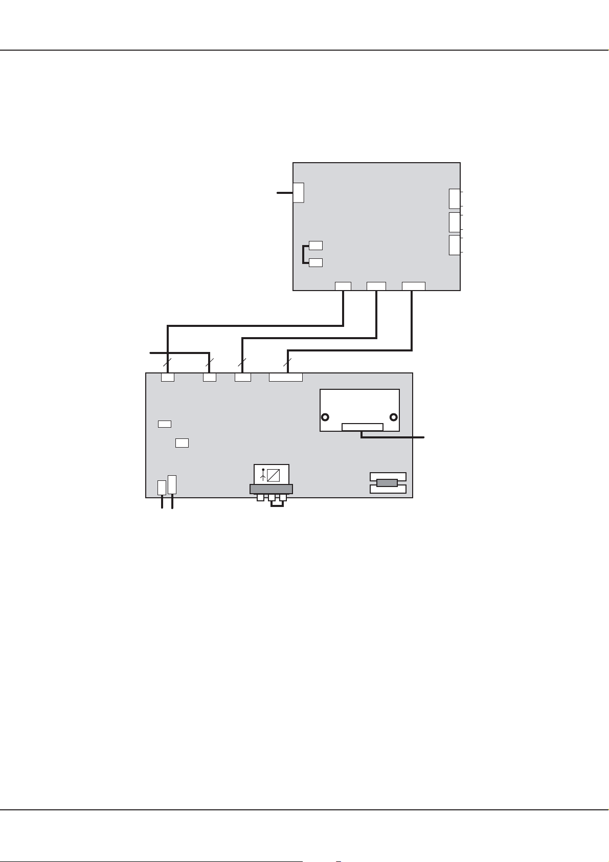
7. Startsequenz
Beschreibung und Pinbelegung
90432.921
300lg
CN11 CN19 CN13
Audio
Power in
4 pin
1,2 GND
3,4 30V
J7
R
CN20
CN2
L
CN29
CN8
Keyboard
7 pin
1,7,18 GND
3 LED (rt/rd)
4 LED (grn)
19 +5VST
20 IR Rec
AV3plusL
90432.901
1 ACPWCK
2 RLYON
3 5V STBY
4 GND
5 VSon
6 FPVRR
7 n.c.
90432.923
Control
7 pin
300lg
Power +5V/+12V in
1 +5VST
2,4,6 GND
3,5 +5V (VCC)
7 +12V
8 PSSTDBY
9 PSDPMS
10 FPVRR
PIP-Tuner
f1
f1
f2
Bolzen für Erdung, Zahnscheibe verwenden
Earth over bolted assembly, use a toothed lock washer
12L
Netzteil Bestandteil des PDP
Power Supply Unit (PSU) Part of PDP
1,2 30V
3,4 GND
Audio
Power
CN802 CN801 CN803
90432.922
200lg
6774
10 pin
N
CON1
roter Sockel
red socket
CN02
CN03
LVDS-Adapter
90432.902
X1
X1
1 GND 11RD+ 19 GND
2 DISPEN 12 RB- 20 R3+
3 SLE 13 GND 21 R34 SCLK 14 RCLK+ 22 GND
5 SDATA 15 RCLK- 23 RA+
6 GND 16 GND 24 RA7-9 n.c. 17 RC+ 25 GND
10 GND 18 RC-
1 ACD
2 RLY ON
3 +5Vst_by 1,2,3 +5V
4 GND 4,5,6 GND
5 Vs ON 7,8 +12V
6 5VD 9,10 GND
7 n.c. 11,12 n.c.
+5VSB and
PSU control
Scart 1
Scart 2
Power
5V / 12V
Startsequenz
CN805CN806CN807
Verkabelung, vormontiert
Wiring, premounted
Startsequenz AV3 Elektronik in Verbindung mit dem Netzteil des Plasmas:
1. Schritt
An CN801 des PDP PSU’s, Pin3, erscheint die Spannung 5VDC.
2. Schritt
CN801, Pin1 (ACDET) schaltet auf ”high”, sobald die Spannung vom Netzteil 90VAC überschreitet. Bleibt
die Spannung unter 90VAC, stoppt die Startsequenz hier (wird durch das AV3 Board unterbrochen).
3. Schritt
Um das Plasma zu starten, wird das Signal RYLON (CN801, Pin2) auf 5V gelegt, dadurch werden auf dem
Netzteil jetzt die Niederspannungen wie z.B. 5V, 12V, 30V, etc., gestartet.
4. Schritt
Das Signal 5VDET (CN801, Pin6) wird überwacht. Wenn das Signal ”low” ist, setzt die AV3 RYLON = 0V
(dadurch wird das Panel wieder abgeschaltet).
5. Schritt
Bei ”high”—Signal (RYLON = 5V) setzt die AV3 Elektronik VSON wird auf ”high” (CN801, Pin5) und schaltet
auch die Hochspannungen hinzu, das Plasma befindet sich im Betrieb.
Technisches Handbuch 15
Page 42
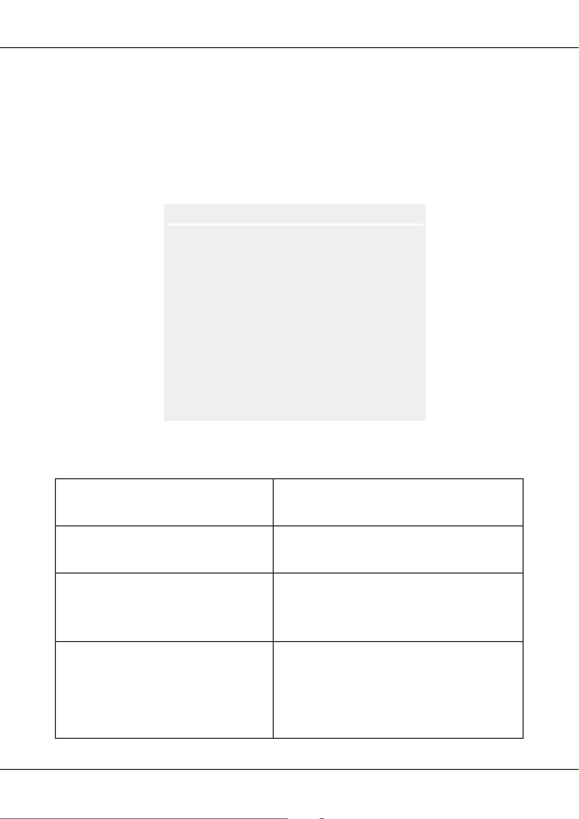
Service OSD
8. Service OSD
Neben dem User—OSD gibt es zusätzlich noch ein Service—OSD, in dem Einstellungen vorgenommen werden
können, die die Performance des Displays ver ndern bzw. für den Service hilfreiche Informationen anzeigen.
Aus diesem Grunde sollte der Zugang zu diesem Menü nur entsprechend ausgebildetem Personal bekannt
sein. Um in das Service—Menü zu gelangen, muss zuerst das normale Menü geöffnet werden (Taste ”Menü”
auf der Fernbedienung), anschliessend kann über die Eingabe des Codes ”8640” das Service—Menü geöffnet
werden.
Es erscheint dann folgendes Fenster (die angezeigten Werte sind Platzhalter und weichen von den tatsächlichen
Einstellungen in den meisten Fällen ab):
Version / System Info
Einstellungen RS232 4800
Kundenlogo -1Betriebsstunden
Farbeinstellung Standard
Eingangsquelle PC (RGB)
Einstellungen Temperatur
Hintergrund Nichts
Sub Laustärke
Alles zurücksetzen
8.1 Submenüs
Folgende Menüpunkte können direkt im Service—Menü eingestellt werden:
Einstellung RS232
Kundenlogo (optional)
Eingangsquelle
Hintergrund
Hier wird die Downloadgeschwindigkeit für ein evtl.
Software—Update eingestellt. Sollte es beim Update
zu Problemen kommen, ist es ratsam, die
Geschwindigkeit zu verringern.
Im internen Speicher der AV—Elektronik sind Logos
verschiedener Kunden abgelegt. Um Irritationen zu
vermeiden sollte diese Einstellung nicht verändert
werden.
Hier wird festgelegt, welche Eingangsquelle bei einem
Neustart des Gerätes aktiv ist. Es stehen sämtliche
Quellen zur Auswahl zur Verfügung, zusätzlich gibt es
die Möglichkeit ”Letzte” einzustellen. Mit dieser Auswahl
startet das Gerät mit der Eingangsquelle, in der es sich
beim Abschalten befunden hat.
Für Servicezwecke (Pixelfehlersuche, Überprüfung von
Einbrenneffekten) ist es hilfreich, ein Bild in den Farben
Rot, Grün, Blau oder Weiss darzustellen. Die jeweilige
Auswahl erscheint nach Schliessen Des Menüs.
Mit der Funktion ”invertiert” wird das im Moment
dargestellte Bild invertiert dargestellt. Diese Funktion
kann helfen, leichte Einbrenneffekte zu beheben. (Es
muss allerdings das ”eingerannte” Bild vorhanden sein.)
Die oben nicht aufgeführten Menüpunkte können über Untermenüs eingestellt werden:
16 Technisches Handbuch
Page 43
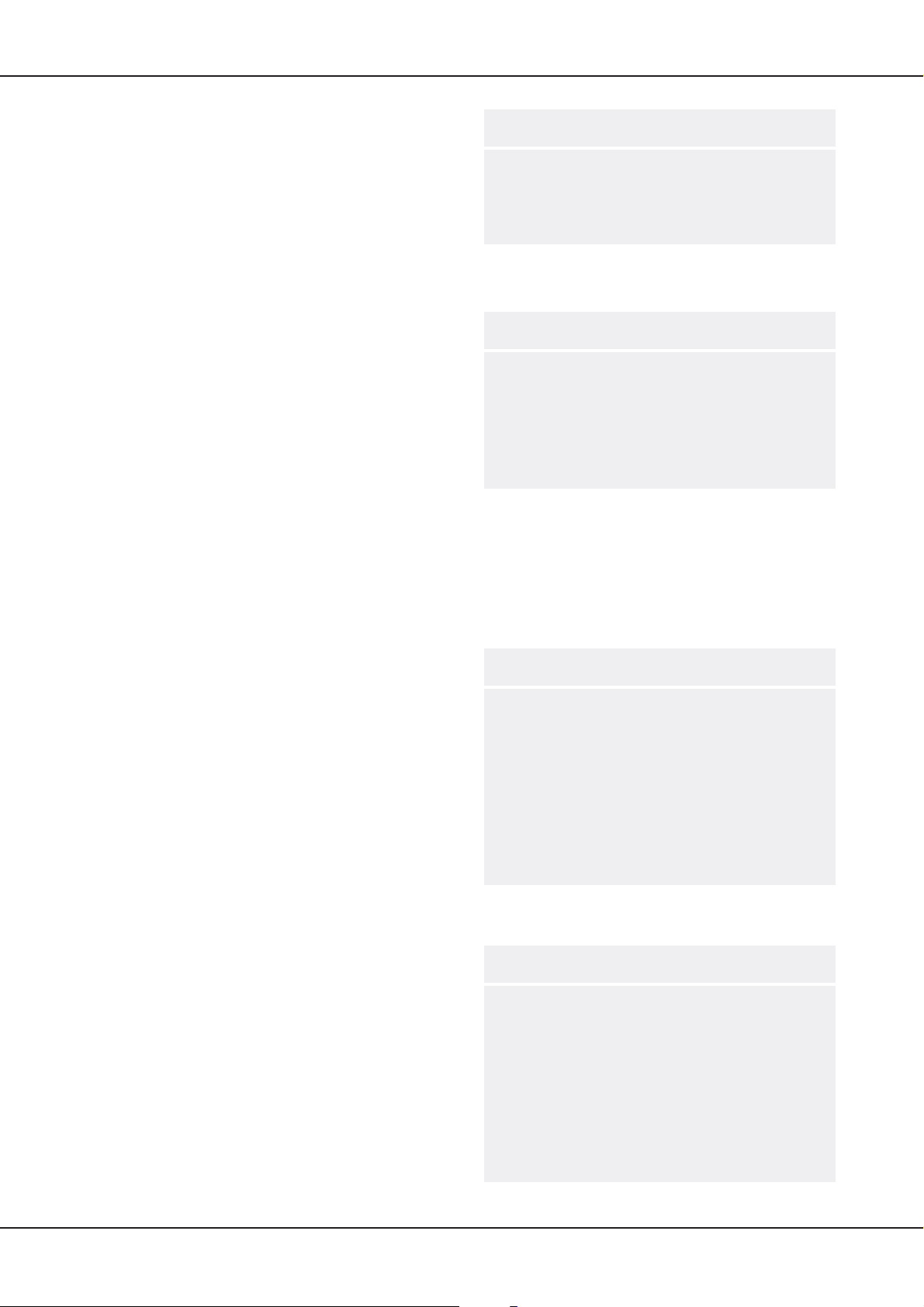
8.1.1 Version / System Info
Im Untermenü Version / System Info wird der aktuelle
Software—Stand, der Hardwarestand und Typ des
Soundprozessors (MSP) angezeigt.
Einstellungen können hier nicht vorgenommen
werden. Für Fälle. in denen eine Rückfrage zum
Hersteller notwendig sein sollte, werden diese Daten
auf jeden Fall verlangt.
8.1.2 Betriebsstunden
Im Untermenü Betriebsstunden werden die
Betriebsstunden des gesamten Gerätes angezeigt
(auch Stand—By—Zeiten) und die Betriebsstunden,
in denen das Panel in Betrieb war.
Über ”Reset” können beide Anzeigen auf ”0”
zurückgesetzt werden. Dies ist sinnvoll, wenn im
Rahmen einer Reparatur z.B. das Panel
ausgetauscht wurde.
ACHTUNG:
zurückgesetzt wird, gibt es keine weitere M glichkeit,
die Betriebsstunden des Gerätes festzustellen. Es
ist dringend ratsam, vor dem Zurücksetzen die
Betriebsstunden zu notieren bzw. auf andere Art
festzuhalten (z.B. Foto).
Wenn hier die Anzeige auf ”0”
Service OSD
Sofware % z
Hardware % z
MSP % z
Betriebsstunden % z
Betriebsstunden Panel % z
Reset
8.1.3 Farbeinstellung Standard
Im Untermenü Farbeinstellung wird die grunds tzliche
Farbeinstellung des Gerätes für alle Eingangsquellen
festgelegt. Die Offset—Werte verändern die
Farbtemperatur des gesamten Displays,
(Hintergrund), die Gain—Werte verändern die
Farbtemperatur des Bildinhalts (Kontrast).
Grundsätzlich sollte man versuchen, evtl.
Farbanpassungen über die Einstellmöglichkeiten im
User—Menü vorzunehmen, in bestimmten
Anwendungen aber kann es notwendig werden, auch
hier Einstellungen vorzunehmen (z.B. Anwendungen
in TV produzierenden Bereichen).
8.1.4 Einstellung Temperatur
Die AV3—Elektronik besitzt eine interne
Temperaturüberwachung, die aus drei Stufen besteht
(siehe hierzu Kapitel 4.9 auf Seite 7)
eingestellten Werte sind für einen optimalen Betrieb
des Gerätes ausgelegt und sollten nur in extremen
Einzelfällen nach Rücksprache mit dem Hersteller
verändert werden. Schäden, die durch vom Hersteller
nicht freigegebenen Änderungen der
Temperaturüberwachung verursacht werden, führen
zum Erlöschen jeglicher Garantieansprüche.
Für Servicezwecke besteht die Möglichkeit, die
abgespeicherten Max.— und Min.—Werte
zurückzusetzten. Dies ermöglicht die Überprüfung,
ob sich das Gerät bei bestimmten Anwendungen
jenseits der erlaubten Temperaturgrenzen befindet.
. Die werksseitig
Rot Offset -123Grün Offset -123Blau Offset -123Rot Gain -123Grün Gain -123Blau Gain -123-
Temperatur 1 -12.3Temperatur 2 -12.3Temperatur 3 -12.3Max. bisherige Temperatur-12.3Min. bisherige Temperatur -12.3Reaet Max/Min
Technisches Handbuch 17
Page 44
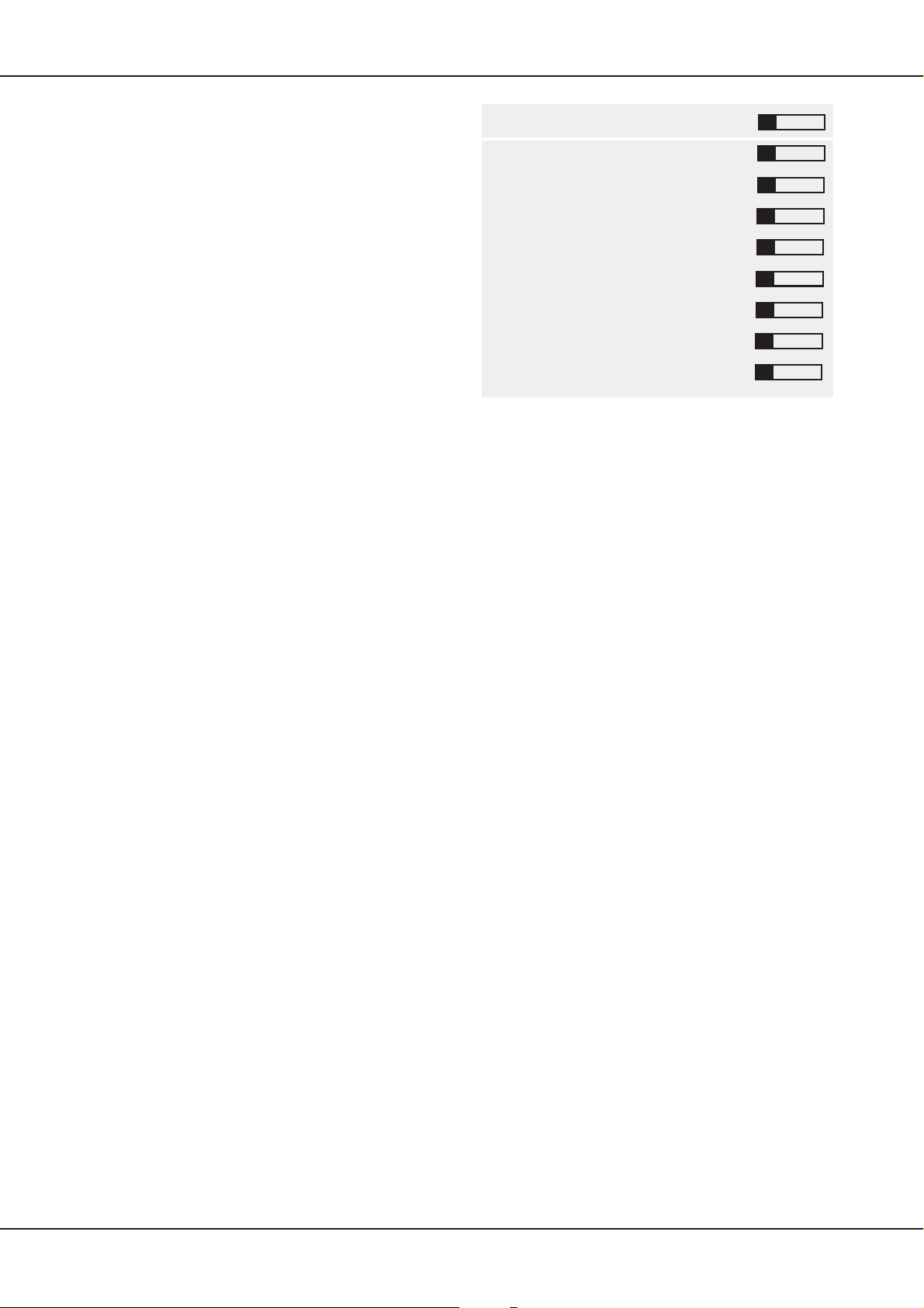
Service OSD
8.1.5 Sub Lautstärke
Im Untermenü Sub Lautstärke wird die Voreinstellung
der Lautstärken beim Einschalten für die einzelnen
Eingangsquellen bzw. Line out Audio—Ausgänge
festgelegt.
Werksseitig sind die Pegel alle auf den selben Wert
eingestellt, vereinzelt können sich die Ausgangspegel von externen Geräten beim Kunden unterscheiden, sodass hier eine entsprechende Anpassung vorgenommen werden kann.
8.1.6 Alles zurücksetzen
Mit Alles zurücksetzen werden alle vorgenommenen
Einstellungen, der Senderspeicher, die Max.—/
Min.—Temperaturen sowie der Betriebsstundenzähler zurückgesetzt, das Gerät wird praktisch
wieder in den werksseitigen Auslieferzustand zurückversetzt.
Dies sollte ebenfalls nur nach Rücksprache mit dem
Hersteller durchgeführt werden, da mit den gelöschten Temperaturen und Betriebsstunden Informationen verloren gehen, die zur Abklärung von Garantieansprüchen notwendigsein können.
CVBS -12PC -12YC -12SCART1 -12SCART2 -12TV -12YUV -12Subwoofer -12Lautstärke ”Audio Out” -12-
18 Technisches Handbuch
Page 45
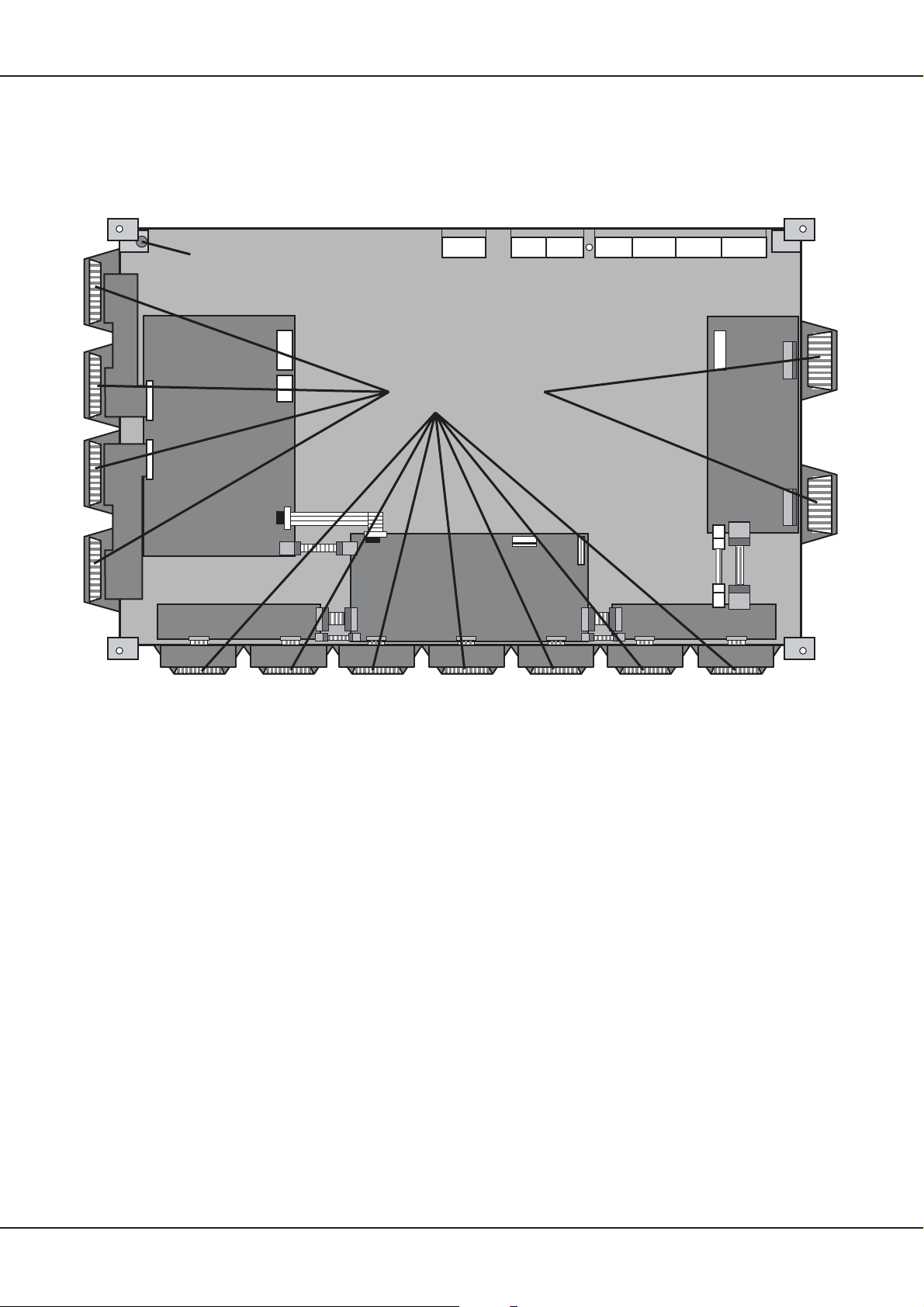
9. Plasma Display
Nachfolgend finden Sie die Beschreibung des Plasma Displays Typ PDP 42V6####.
9.1 Rückansicht mit Leiterplatten
Plasma Display
E/X Tube
1234567
Type Labels
Flex Cable
Y-SUS
Controller
Signal Input
X left X right
(R, G, B, H/V Sync)
Z-SUS
Bei einem eventuellen Reparaturaustausch des Panels ist besonders auf die sog. E/X Tube zu achten.
Über diese versiegelte Glasröhre wird das Display zuerst entlüftet, anschliessend mit Edelgas befüllt. Ein
Bruch an dieser Stelle führt automatisch zum Totalverlust des Panels. Ebenso ist beim Wechsel auf die
Flex—Kabel zu achten, Schäden führen ebenfalls zum Totalverlust, da diese zwischen den beiden
Glassscheiben des Panels eingeschweisst sind.
Auf den sog. Type Labels befinden sich die Typenbezeichnung des Panels, ebenso wie die Seriennummer.
Diese Bezeichnungen sollten bei einem Reparaturaustausch auf den Lieferpapieren vermerkt sein.
9.2 Schematischer Aufbau
Der schematische Aufbau des Panels zeigt auf, welche Leiterplatten zusammen gehören und welche
Signale auf das Panel geführt werden. Die angegebenen Spannungen Vs, Va und Vcc kommen vom
Netzteil, das Bestandteil des Plasmadisplays ist. Ein Wechsel des Netzteils durch ungeschultes Personal
ist nicht ratsam, da die Spannungen auf dem Netzteil panelspezifisch angepasst werden müssen.
Technisches Handbuch 19
Page 46
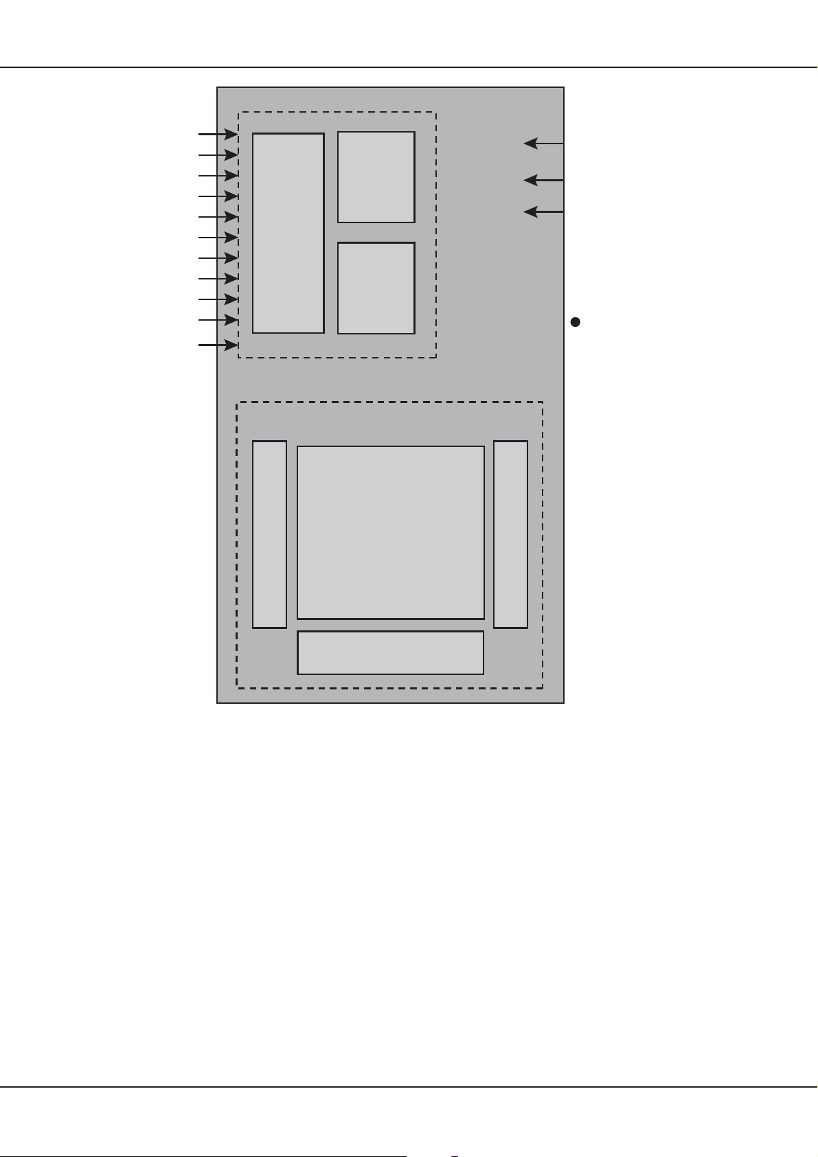
Plasma Display
(LVDS Input)
RxD+
RxDRxC+
RxCRxB+
RxBRxA+
RxARxCLK+
Serial Interface
Input
Interface
Controller
Scan Driver
Memory
Controller
Driver
Timing
Controller
Color Plasma
Display Panel
852 x 480 pixels
Vs (180V~190V)
Va (55V~65V)
Va (+5V)
Die angegebenen
Spannungen liegen
an, wenn ein komplettes Weissbild
dargestellt wird.
Adress Driver
Common Sustain Driver
20 Technisches Handbuch
Page 47
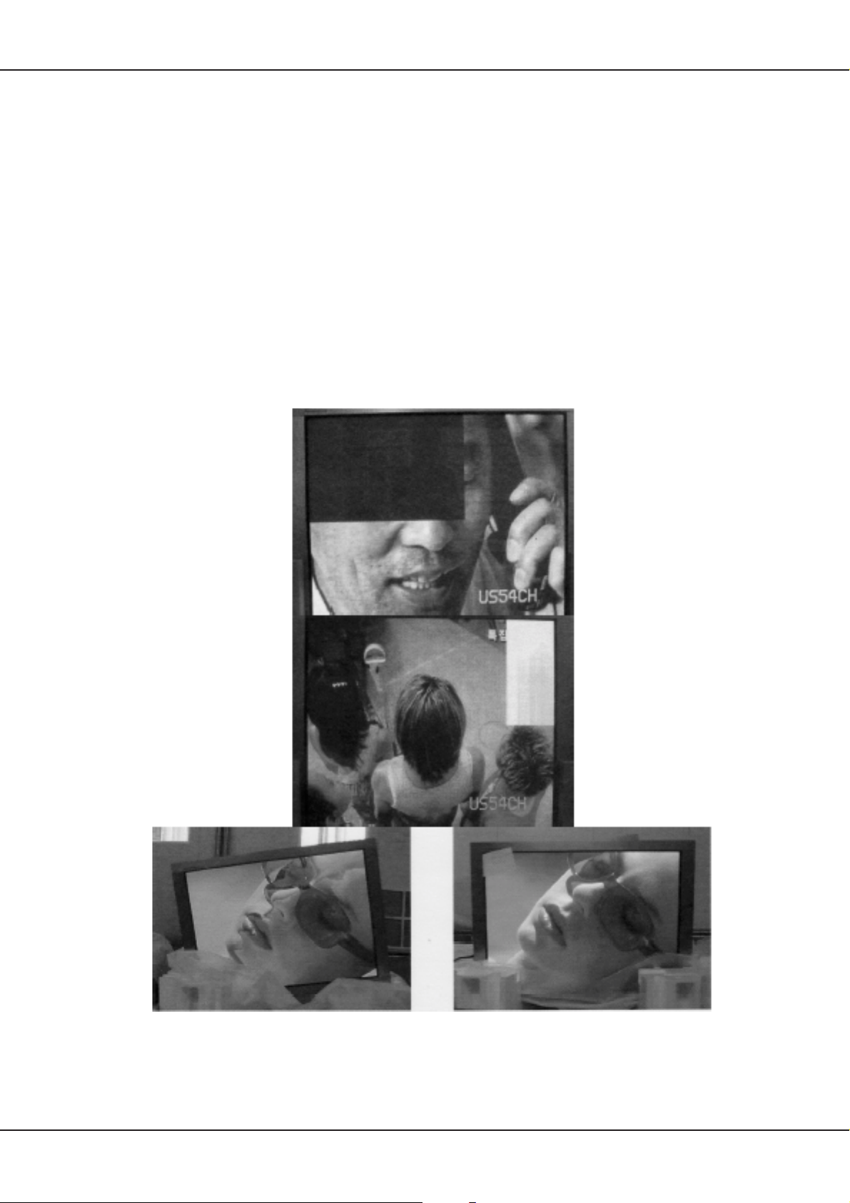
Plasma Display
9.2.1 Lebenszeit
Die Lebenszeit des Panels definiert sich über die Helligkeit, d.h. sobald die Helligkeit 50% des Anfangswertes
erreicht hat, ist das theoretische Ende der Lebenszeit erreicht. Der Hersteller gibt für dieses Panel eine
durchschnittliche Lebenszeit von 60.000 Stunden an.
9.2.2 Typische Fehler
Die nachfolgend aufgeführten Beispiele sind typische Panelfehler. Es kann stets davon ausgegangen werden,
dass Fehler, bei denen Zeilen oder Spalten ganz oder teilweise fehlen, durch einen Fehler auf dem Plasma
verursacht werden und nicht durch externe Elektronik.
Abnormal Normal
Technisches Handbuch 21
Page 48
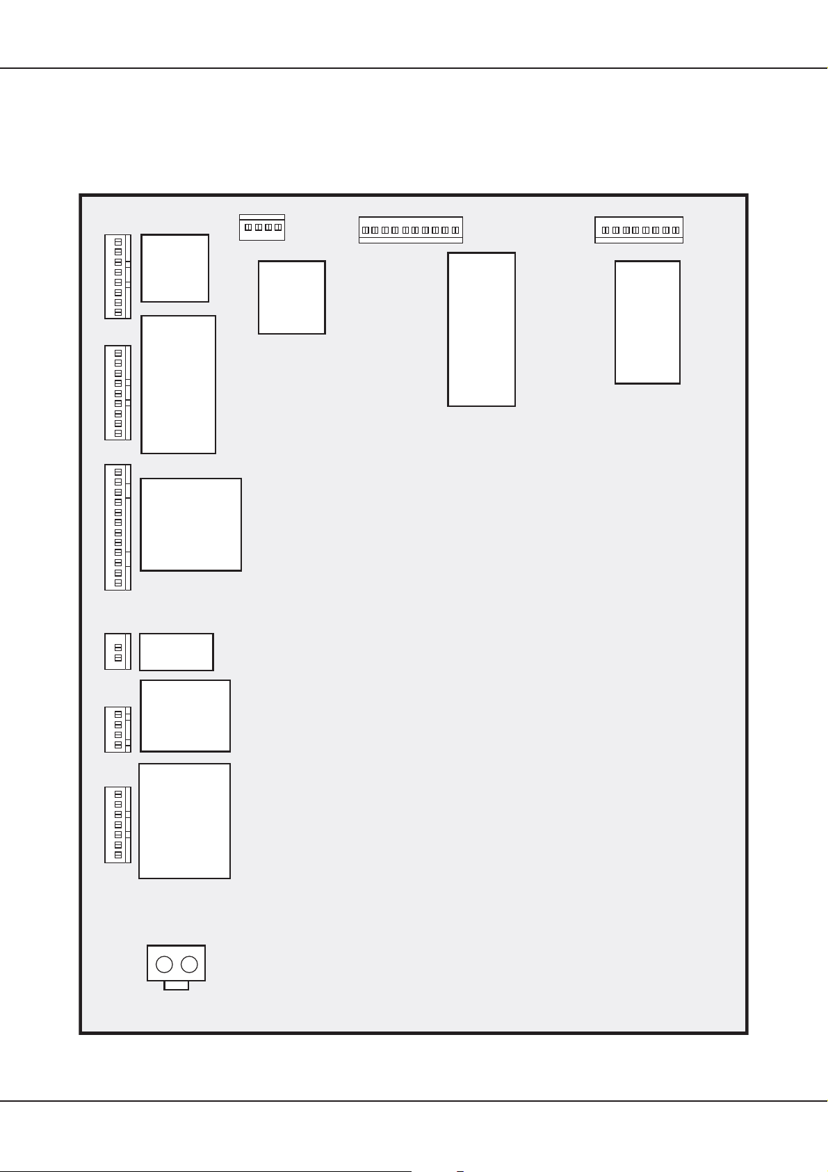
Plasma Display
9.3 Netzteil
Um eventuelle Fehler des Plasmas festzustellen, ist es am einfachsten, die Spannungen auf dem Netzteil zu
überprüfen. Zu beachten ist dabei allerdings, dass im Fehlerfall nicht alle Spannungen vorhanden sind, da
das Netzteil auf eine Rückmeldung des Panels angewiesen ist
die schematische Darstellung des Netzteils mit der entsprechenden Steckerbeschreibung.
(siehe hierzu Kapitel 7. auf Seite 15)
. Nachfolgend
CN808
1
2
3
4
5
6
7
8
CN804
1
2
3
4
5
6
7
8
9
CN803
1
2
3
4
5
6
7
8
9
10
11
12
#1 ~ #4
: +5Vctrl
#5 ~ #8
: GND
#1 : 9Vsc
#2 : 9Vsc
#3 : GND
#4 : 5Vsc
#5 : 5Vsc
#6 : 5Vsc
#7 : GND
#8 : GND
#9 : GND
#1 ~ # 3 : 5Vsc
#4 ~#6 : GND
#7, #8 : 12Vsc
#9, #10 : GND
#11, #12 : NC
CN805
#1 ~ #2
: GND
#3 ~ #4
: +5Vctrl
10 9 8 7 6 5 4 3 2 1 8 7 6 5 4 3 2 1
CN806
#1 : Vs
#2 : Vs
#3 : Vs
#4 : NC
#5 : GND
#6 : GND
#7 : GND
#8 : GND
#9 : Va
#10 : Va
#1 : Vs
#2 : Vs
#3 : NC
#4 : GND
#5 : GND
#6 : Va
#7 : GND
#8 : #5V
CN807
CN809
1
2
CN802
1
2
3
4
CN801
1
2
3
4
5
6
7
#1 : 9Vsc
#2 : GND
#1 ~ #2
: 30V or 24V
#3 ~ #4
: GND
#1 : ACD
#2 : RLY ON
#3 : 5Vst_by
#4 : GND
#4 :Vs On
#6 : 5VD
#7 : NC
CN01
12
Form inlet
22 Technisches Handbuch
Page 49
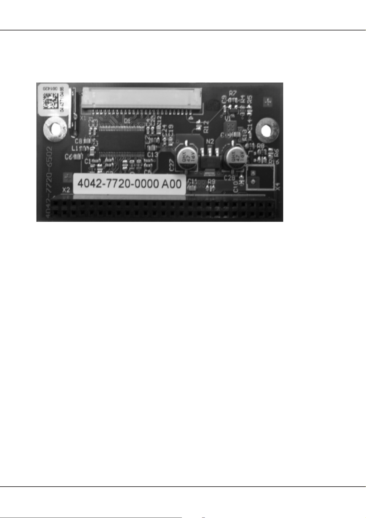
LVDS-Interface-Board
10. LVDS-Interface-Board
Das am Ausgang der AV3 anliegende LVTTL—Signal wird auf dem LVDS—Interface—Board in das zum
Betrieb des Plasmas notwendige LVDS—Signal umgewandelt (LVDS= Low Voltage Differential Signal).
Das Board ist über den Stecker X2 fest mit der AV3—Elektronik verbunden, das umgewandelte Signal (LVTTL
nach LVDS) geht von X1 direkt auf das Logic—Board des Plasmadisplays. Die Spannungsversorgung des
LVDS—Transmitter—IC’s erfolgt ebenfalls über den Stecker X2 (Pin 15 —18 = +5V; Pin 1, 2, 19, 20, 29, 30,
39, 40, 49, 50 = GND)
Technisches Handbuch 23
Page 50
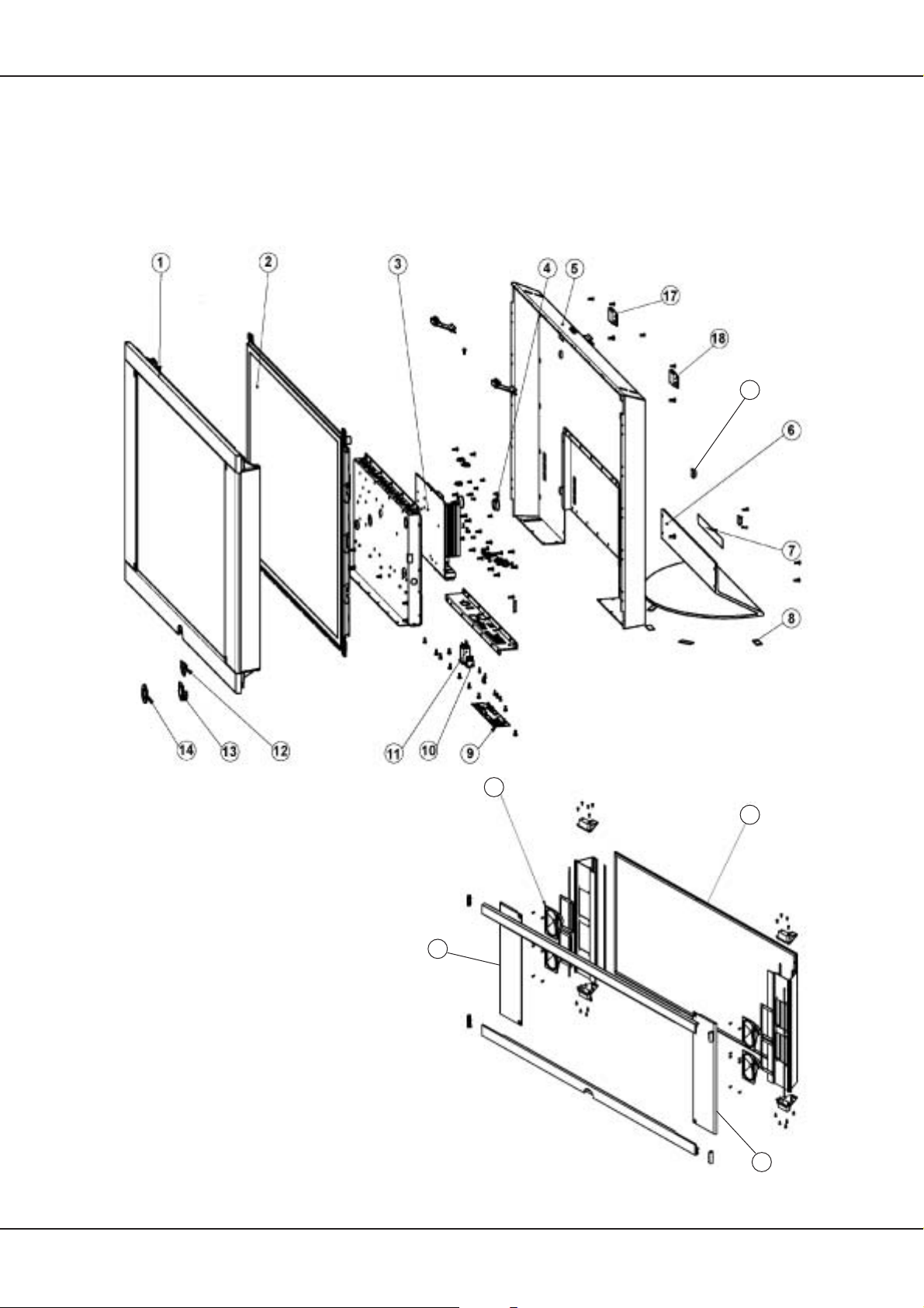
Explosionszeichnung
11. Explosionszeichnung
Nachfolgend finden Sie die Explosionszeichnungen des Ger tes und, aus Übersichtlichkeitsgründen separat
aufgeführt, die Explosionszeichnung des Frontrahmens. Die aufgeführten Nummern verweisen auf die jeweilige
Position in der Ersatzteilliste.
19
20
15
16
20
24 Technisches Handbuch
Page 51
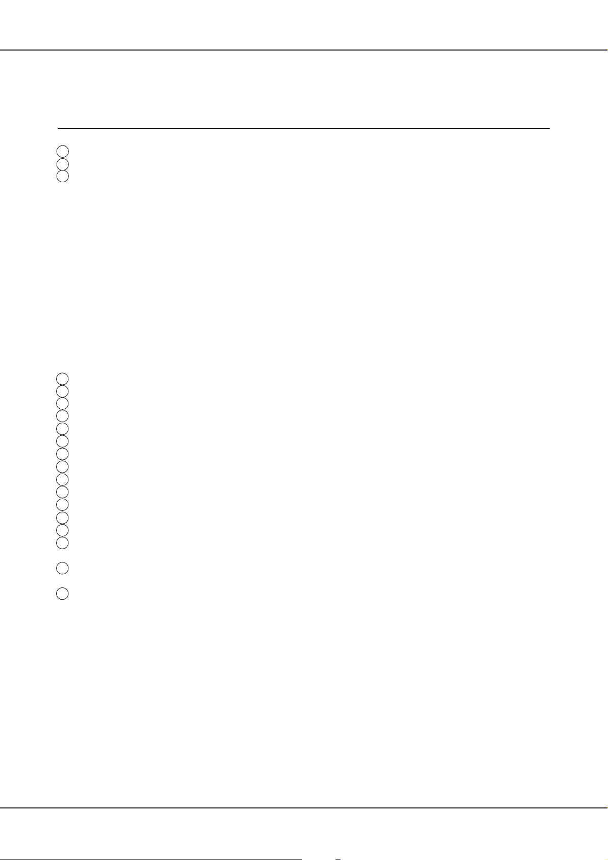
Ersatzteilliste
12. Ersatzteilliste
CONCEPT L 42 Art.-Nr. 64403x60
Pos.Nr. Bestell-Bezeichnung Description Bestell-Nr.
ItemN°. List Part N°.
BAUGRUPPEN UNITS
2 PLASMA-DISPLAY 42 ZOLL CONCEPT 42 L4200 .......PLASMA-DISPLAY 42 ZOLL ................................ 345-90432.900
3 SIGNAL BOARD AV3 PLUS L ........................................SIGNAL BOARD AV3 PLUS L .............................. 396-90432.901
12 IR-EMPFAENGER KPL. CONCEPT 42.......................... IR SENSOR CPL. CONCEP 42 ............................ 396-90432.903
U 0103 LVDS INTERFACE BOARD ............................................ LVDS INTERFACE BOARD.................................. 396-90432.902
DRUCKSACHEN OPERATING INSTRUCTIONS
801 BAN -D-I CONCEPT L 42 ALS PDF FILE .............. OIN -D-I CONCEPT L 42 ...................................... 233-32241
801 BAN -E-GB CONCEPT L 42 ALS PDF FILE .............. OIN -E-GB CONCEPT L 42 .................................. 233-32241.010
801 BAN -NL-F CONCEPT L 42 ALS PDF FILE ..............OIN -NL-F CONCEPT L 42 ................................... 233-32241.020
GERÄTEBEIPACK SET SUPPLEMENT
900 RC4 PLATIN .................................................................... RC4 PLATINUM .................................................... 263-89800.A00
N 0811 VERBINDUNGSKABEL 140MM HF/HF .......................... CONNECTING CABLE 140M ............................... 169-90432.919
VERPACKUNGSMATERIAL PACKING MATERIAL
J 0802 VERPACKUNGSKARTON CONCEPT 42 ......................PACKING CASE CONCEP ................................... 245-90432.905
J 0803 VERPACKUNGSECKE CONCEPT 42 OBEN 2 ST. ......PROTECTIVE PACKING TOP 2 PIECE............... 256-90432.906
J 0803 VERPACKUNGSECKE CONCEPT 42 UNTEN 2 ST..... PROTECTIVE PACKING BOT 2 PIECE............... 256-90432.907
VERBINDUNGSLEITUNG CONNECTING CABLES
N 0300 NETZKABEL GRAU 2,5M STECKBAR .......................... POWER CORD ...................................................... 170-90432.918
GEHÄUSETEILE CABINET MOUNTING
1 FRONTRAHMEN PLATIN CONCEPT L 42.................... FRONT FRAME PLATINUM ................................. 778-90432.916
1 FRONTRAHMEN PLATIN CONCEPT L 42.................... FRONT FRAME ANTHRACITE ............................ 786-90432.911
5 RUECKWAND CONCEPT L 42 ......................................BACKCOVER CONCEPT ..................................... 775-90432.909
6 TISCHFUSS PLATIN CONCEPT L 42 ............................ TABLE STAND PLATINUM................................... 484-90432.914
6 TISCHFUSS PLATIN CONCEPT L 42 ............................ TABLE STAND ANTHRACITE.............................. 484-90432.915
8 FILZGLEITER FELT ........................................................ STRIP .................................................................... 414-90432.935
13 IR-GEHÄUSE...................................................................IR CABINET ........................................................... 396-90432.903
14 BLENDE (DECORRING) CONCEPT 42 ......................... COVER (DECORRING) CON ............................... 778-90432.916
16 FRONTSCHEIBE CONCEPT 42..................................... FRONT PANE CONCEPT ..................................... 666-90432.904
17 WANDHALTER LINKS CONCEPT 42 ............................ WALL MOUNT BRACKET LEFT........................... 786-90432.912
18 WANDHALTER RECHTS CONCEPT 42........................ WALL MOUNT BRACKET RIGHT ........................ 786-90432.913
19
20 LAUTSPRECHERGITTER .............................................. SPEAKER GRILLE PLATINUM ............................ 708-90432.938
20 LAUTSPRECHERGITTER .............................................. SPEAKER GRILLE ANTHRACITE ....................... 708-90432.939
15 LAUTSPRECHER 4 OHM 10W 4 STÜCK ......................LOUDSPEAKER 4 OHM 10W 4 PIECE ............... 272-90432.908
10 NETZSCHALTER SCHWARZ......................................... POWER SWITCH BLACK..................................... 471-90432.920
N 0001 KABELBAUM 2-POL. 300MM BL/BN ............................. CABLE HARNESS 2-POL 300MM ........................ 171-90432.929
N 0002
N 0003 KABELBAUM 1-POL. 100MM BN ................................... CABLE HARNESS 1-POL 100MM........................ 171-90432.927
N 0004 KABELBAUM 1-POL. 100MM BL .................................... CABLE HARNESS 1-POL 100MM........................ 171-90432.928
N 0008 KABELBAUM 7-POL. 650MM AV3 CN8 <=> IR X1 ....... CABLE HARNESS 7-POL 650MM........................ 171-90432.931
N 0009 KABELBAUM 1-POL. 150MM SZL .................................CABLE HARNESS 1-POL 150MM........................ 171-90432.926
N 0011
N 0013
N 0019
N 0020
N 0024
N 0025
N 0029
N 0031 KABELBAUM 300MM LVDS X1 <=> PDP P31 .............. CABLE HARNESS 300MM ................................... 171-90432.924
N 0810 VIDEOKABEL 2000MM VGA/DVI ................................... VIDEOCABLE 2000MM......................................... 169-90432.925
ABSTANDSHALTER SELBSTKLEBEND F. RW. B. WANDM
LAUTSPRECHER SPEAKERS
SCHALTER SWITCHES
SPEZIALTEILE SPECIAL PARTS
KABELBAUM 2-POL. 100MM BL/BN PSU CN02 <=>PSU CN03
KABELBAUM 4-POL. 300MM PSU CN802<=>AV3 CN11
KABELBAUM 6-POL. 200MM PSU CN803<=>AV3 CN13
KABELBAUM 7-POL. 300MM PSU CN801<=>AV3 CN19
KABELBAUM 2-POL. SW/RT LAUTSPRECHER ANSCHL
KABELBAUM 1-POL. SW LAUTSPRECHER VERBIND
KABELBAUM 1-POL. SW LAUTSPRECHER VERBIND.
KABELBAUM 2-POL. SW/WS LAUTSPRECHER ANSCHL. ..
. SPACER, ADH. ..................................................... 602-90432.936
. CABLE HARNESS 2-POL 100MM ........................ 171-90432.930
... CABLE HARNESS 4-POL 300MM ........................ 171-90432.921
... CABLE HARNESS 6-POL 200MM ........................ 171-90432.922
... CABLE HARNESS 7-POL 300MM ........................ 171-90432.923
.... CABLE HARNESS 2-POL ..................................... 171-90432.932
.... CABLE HARNESS 1-POL..................................... 171-90432.934
... CABLE HARNESS 1-POL ..................................... 171-90432.934
CABLE HARNESS 2-POL ..................................... 171-90432.933
Technisches Handbuch 25
Page 52

Änderungen vorbehalten
Subject to modification
Modification réserves
Con riserva di modifiche
Reservado el derecho a introducir modificaciones
Wijzigingen voorbehouden
Page 53

Einbauanweisung für
Concept L42
Tuner 009 89525 060
Installation instructions for
Concept L42
Tuner 009 89525 060
240 - 32496 000 04 - 2005
1
Page 54

Inhalt Indice Index
Inhoud Sommaire Indice
Deutsch 3
English 6
Concept L42 9 - 11
Änderungen vorbehalten
Subject to modifi cation
2
Page 55
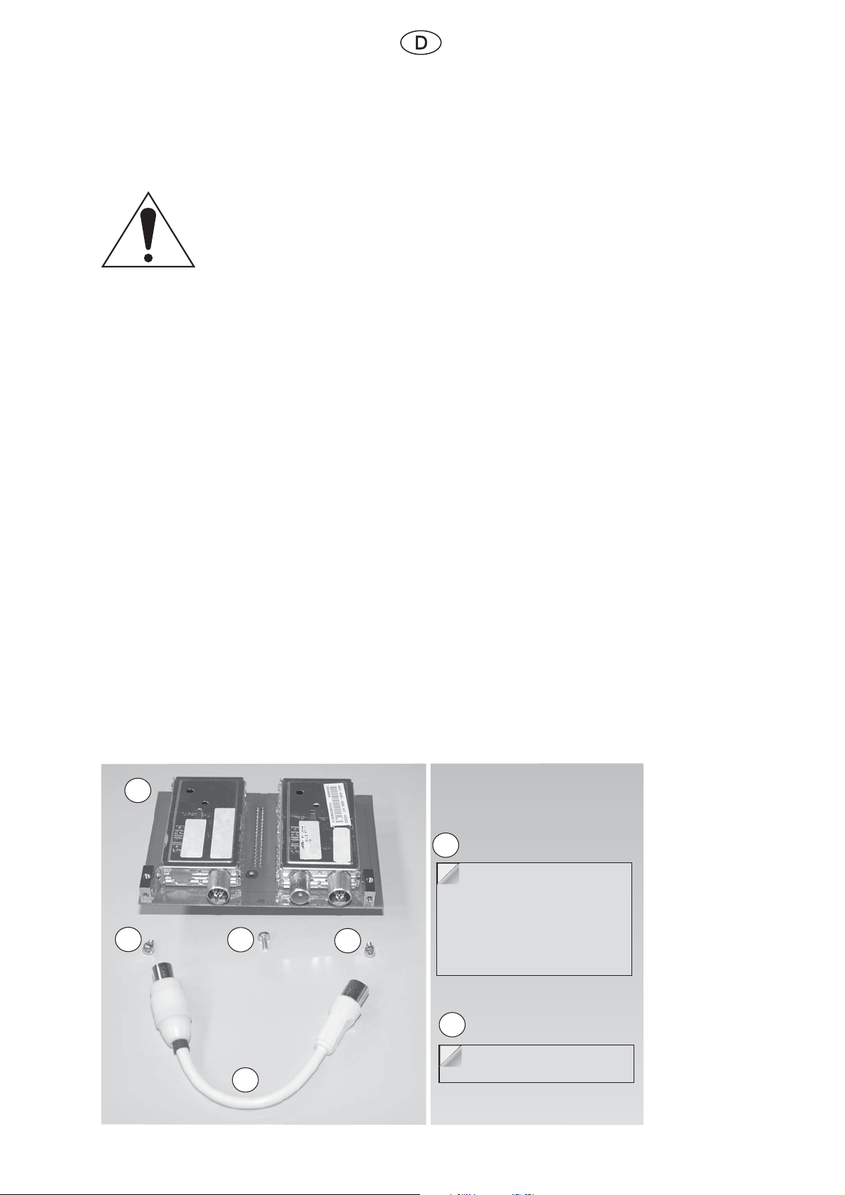
Sicherheit
Folienzuschnitt,
vor dem Aufkleben Klebefolie frei legen
1
2
2
2
3
4
Kupferstreifen
3a
Diese Einbauanweisung soll dem Techniker die Montage erleichtern.
Die Einbauanweisung (kurz EBA genannt) ist nicht für den Endkunden bestimmt.
Achtung
Das Warndreieck kennzeichnet Hinweise zum Schutz von Personen, Geräten
und Umwelt.
Warnhinweise stehen eingerückt und tragen eine fettgedruckte Überschrift.
Beachten Sie diese Hinweise.
Hinweis
Diese Anleitung beschreibt den Einbau des Rüstsatzes 009 89525 060
in das TV-Gerät CONCEPT L42 .
Die Zahlen „(X)“ in Klammern stehen für die Positionsnummer des unter dem Gliederungspunkt „1“
aufgezählten Inhaltes.
1. Benötigte Einbauteile (Bestellnummer: 89525 060)
Pos. Nr. Anzahl Bezeichnung
(1) 1 Tunermodul
(2) 3 Schrauben M3x6 für Tunerbefestigung
(3) 1 Folienzuschnitt für Tuner
(3a) 1 Kupferstreifen (neu für Seite 9, Abb. 4, Pfeil 1)
(4) 1 Verbindungsleitung für Tuner
Abb. 1
3
Page 56
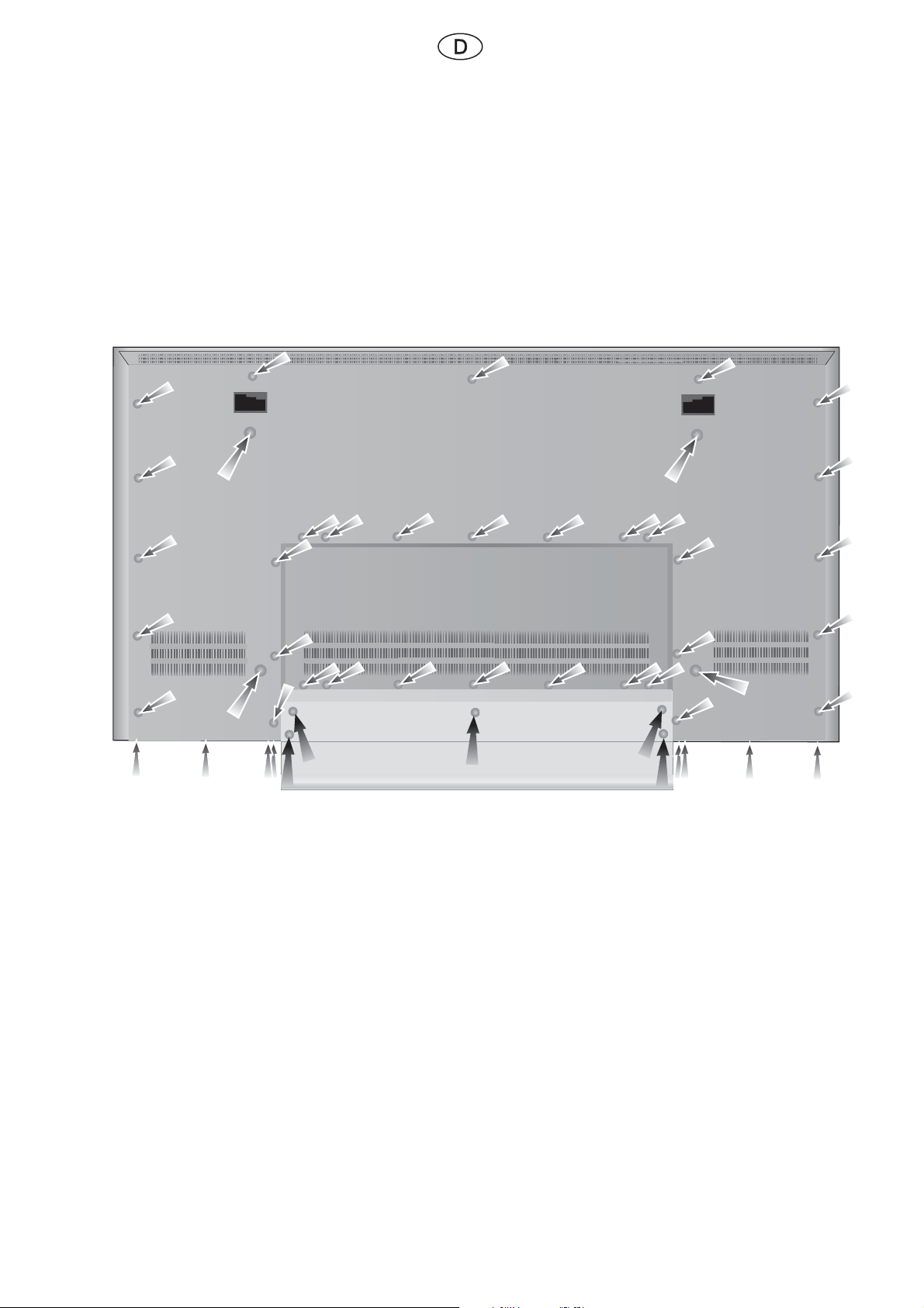
2. TV-Gerät öffnen
Ziehen Sie den Netzstecker.
Entfernen Sie die Anschlussleitungen vom TV-Gerät.
Legen Sie das TV-Gerät fl ach auf ein Vlies oder eine Decke um Beschädigungen am Gehäuse zu vermeiden.
Lösen und entfernen Sie die auf der nachfolgenden Abb. 2 mit Pfeilen markierten Schrauben (50 Schrauben).
Zu lösende Rückwand und Standfußschrauben für TV-Gerät Concept L42
Abb. 2
Anschließend nehmen Sie die Rückwand nach oben vorsichtig ab.
Hinweis
Die auf der Rückwand aufgesteckten Kontaktfedern (wichtig für EMV) dürfen nicht verloren gehen.
Achten Sie später beim Anbringen der Rückwand, dass die Kontaktfedern (Bronzefedern ca. 28 mm
lang) an der Rückwand vorhanden sind.
4
Page 57

3. Einbau des Modules
Mos-Bauteile
Vermeiden Sie Schäden durch elektrostatische Aufl adung.
Beachten Sie die Regeln im Umgang mit MOS-Bauteilen.
Hinweis
Entsprechende Abbildungen zum Einbau des Tuners fi nden Sie in dieser Anleitung auf den Seiten 9
bis 11. Das TV-Gerät erst wieder senkrecht stellen, wenn Rückwand und Fuß am TV-Gerät montiert.
Vorgehensweise
Um beim Einbau des Tunermodules die Arbeit zu erleichtern haben Sie den Standfuß vom Concept L42 abmontiert.
Lösen und entfernen Sie die Halteschrauben zwischen dem Trägerteil und den Buchsen auf der
Leiterplatte (Seite 9, Abb. 3, Bezugslinien a1 bis a9).
Lösen und entfernen Sie die markierten Halteschrauben für das Trägerteil (zu entfernende
Schrauben: Seite 9, Abb. 3, Pfeile b1 bis b6).
Die Schraube, wie auf Seite 9, Abb. 3, Pfeil B dargestellt lösen Sie nur.
Achten Sie auf den Kupferklebestreifen (Seite 9, Abb.4, Pfeil1)
Drehen Sie das Trägerteil, wie auf Seite 9, Abb. 4, dargestellt.
Prüfen Sie den einwandfreien Zustand des Steckers (Tunermodul).
Setzen Sie das Tunermodul in die Steckerleiste ein (Seite 10, Abb. 5, weißer Rahmen).
Drehmoment zum Festziehen der Schrauben: kleiner gleich 0,5 Nm.
Drehen Sie das Trägerteil wieder in die Ausgangslage zurück und schrauben Sie die entfernten
Schrauben wieder ein (Trägerteil und Buchsen auf Leiterplatte Abb. 3, sowie Trägerteil Schrauben). Kleben Sie den Kupferklebestreifen (Seite 9, Abb. 4, Pfeil 1), so wie zuvor wieder an,
bzw. erneuern Sie den Kupferklebestreifen.
Drehen Sie die drei Befestigungsschrauben für das Tunermodul ein (Seite 10, Abb. 6, Pfeile 1
bis 3).
Ziehen Sie die Schutzfolie am Folienzuschnitt ab.
Kleben Sie den Folienzuschnitt, wie auf der Seite 11, Abb. 7 dargestellt, auf Tuner und Trägerteil.
Der Folienzuschnitt verhindert mögliche Störprobleme.
Stecken Sie das mitgelieferte Verbindungskabel am Tuner ein (Seite 11, Abb. 7).
Drücken Sie mit einem geeigneten Werkzeug das Loch für die spätere Rückwandschraube
durch den aufgeklebten Folienzuschnitt (Seite 11, Abb. 7, Pfeil).
Setzen Sie die Rückwand wieder ein.
Drehen Sie die vorher entfernten Schrauben wieder ein und beachten Sie das Drehmoment
kleiner gleich 0,5 Nm.
Führen Sie eine Sicherheitskontrolle (nach VDE 0701) durch.
Führen Sie eine Funktionskontrolle durch.
5
Page 58
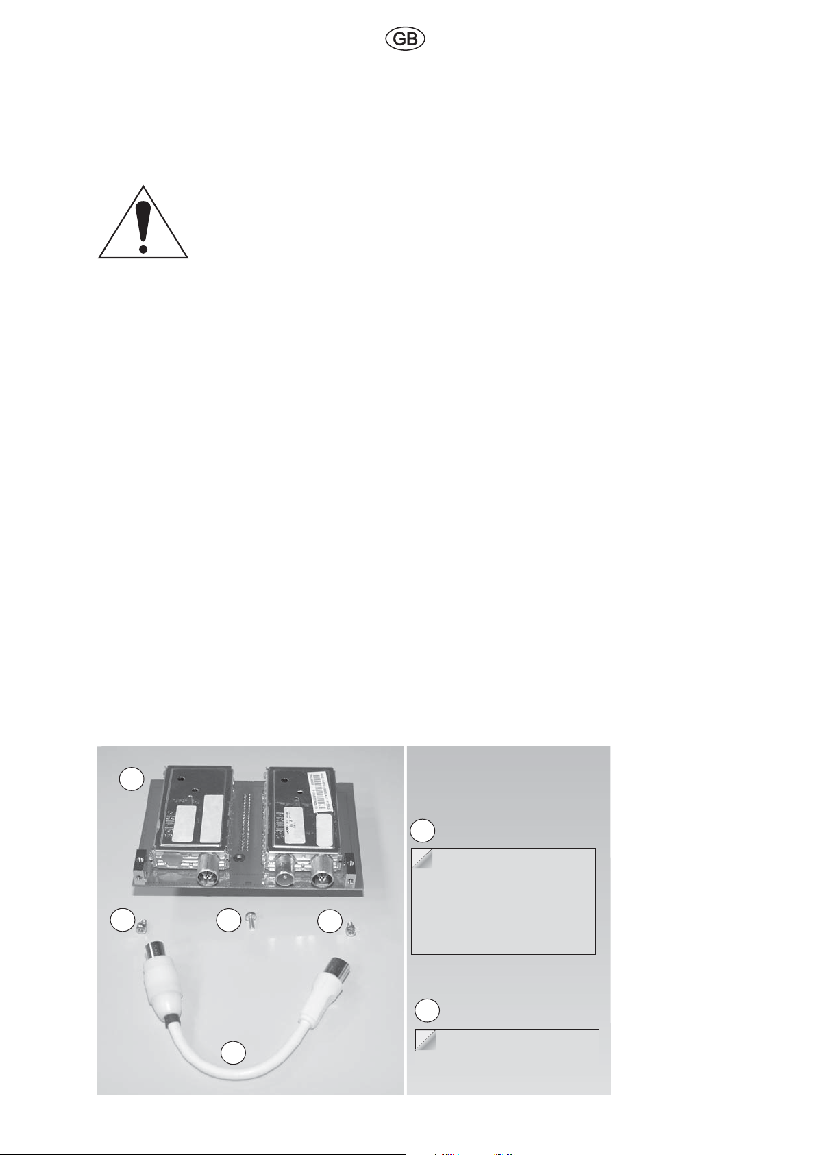
Safety
Cut to size foil
pull off backing to expose adhesive
before applying
1
2
2
2
3
4
copper strips (page 9, fig. 4, arrow 1)
3a
These instructions are intended to make assembly easier for the engineer.
These installation instructions are not intended for the end customer.
Attention
The warning triangle indicates instructions for the protection of persons,
equipment, and the environment.
Warnings are indented and have a bold heading.
Follow these instructions.
Note
These instructions describe the installation of the retrofi t kit 009 89525 060
for the CONCEPT L42 TV set.
The numbers in brackets ”(X)” indicate the item number of the contents listed under section ”1”.
1. Installation parts required (order no.: 89525 060)
Item No Quantity Name
(1) 1 Tuner module
(2) 3 M3x6 screws for fastening the tuner
(3) 1 Cut to size foil for tuner
(3a) 1 copper strips (page 9, fi g. 4, arrow 1)
(4) 1 Connecting lead for tuner
Fig. 1
6
Page 59

2. Opening the TV set
Pull out the mains plug.
Remove the connecting cables from the TV set.
Place the TV set fl at on a piece of felt or a blanket to avoid damaging the housing.
Loosen and remove the screws (50 screws) marked by the arrows in fi g. 2 below.
Removable rear panel and stand base screws for the Concept L42 TV set
Fig. 2
Then carefully remove the rear panel upwards.
Note
The contact springs (important for EMC) plugged into the rear panel may not be lost. Make sure
the contact springs (bronze springs about 28 mm long) are plugged into the rear panel later when
remounting it.
7
Page 60
3. Installation of the module
MOS components
Avoid damage from electrostatic charging.
Observe the rules for handling MOS components.
Note
The appropriate fi gures for installation of the tuner can be found in these instructions on pages 9 to 11.
Do not stand the TV set upright again until the rear panel and stand base have been mounted on the TV.
Procedure
To simplify installation of the tuner module you have removed the stand base from the Concept L42.
Loosen and remove the fastening screws between the carrier and the sockets on the circuit
board (page 9, fi g. 3, reference lines a1 to a9).
Loosen and remove the marked fastening screws for the carrier (screws to be removed: page
9, fi g. 3, arrows b1 to b6).
The screw shown on page 9, fi gure 3, arrow B is only loosened.
Please observe the copper strips (page 9, fi g. 4, arrow 1).
Turn the carrier as shown on page 9, fi g.4.
Check that the plug is free of defects (tuner module).
Insert the tuner module in the connector strip (page 10, fi g. 5, white frame).
Torque for tightening the screws: less than or equal 0.5 Nm.
Turn the carrier back to the starting position and screw the removed screws back in (carrier
and sockets on circuit board, fi g. 3 and carrier screws).
Re-stick the copper strips (page 9, fi g. 4, arrow 1), as before, or renew the copper strips.
Screw in the three fastening screws for the tuner module (page 10, fi g. 6, arrows 1 to 3).
Pull off the backing foil from the cut to size foil.
Stick the foil to the tuner and carrier as shown on page 11, fi g. 7.
The foil prevents possible interference problems.
Plug in the enclosed connecting lead to the tuner (page 11, fi g. 7).
Press the hole for the later rear panel screw through the stuck on foil with a suitable tool
(page 11, fi g. 7, arrow).
Replace the rear panel.
Reinsert the previously removed screws and tighten with the correct torque.
Less than or equal 0.5 Nm
Conduct a safety check according to VDE 0701.
Conduct a functioning check.
8
Page 61
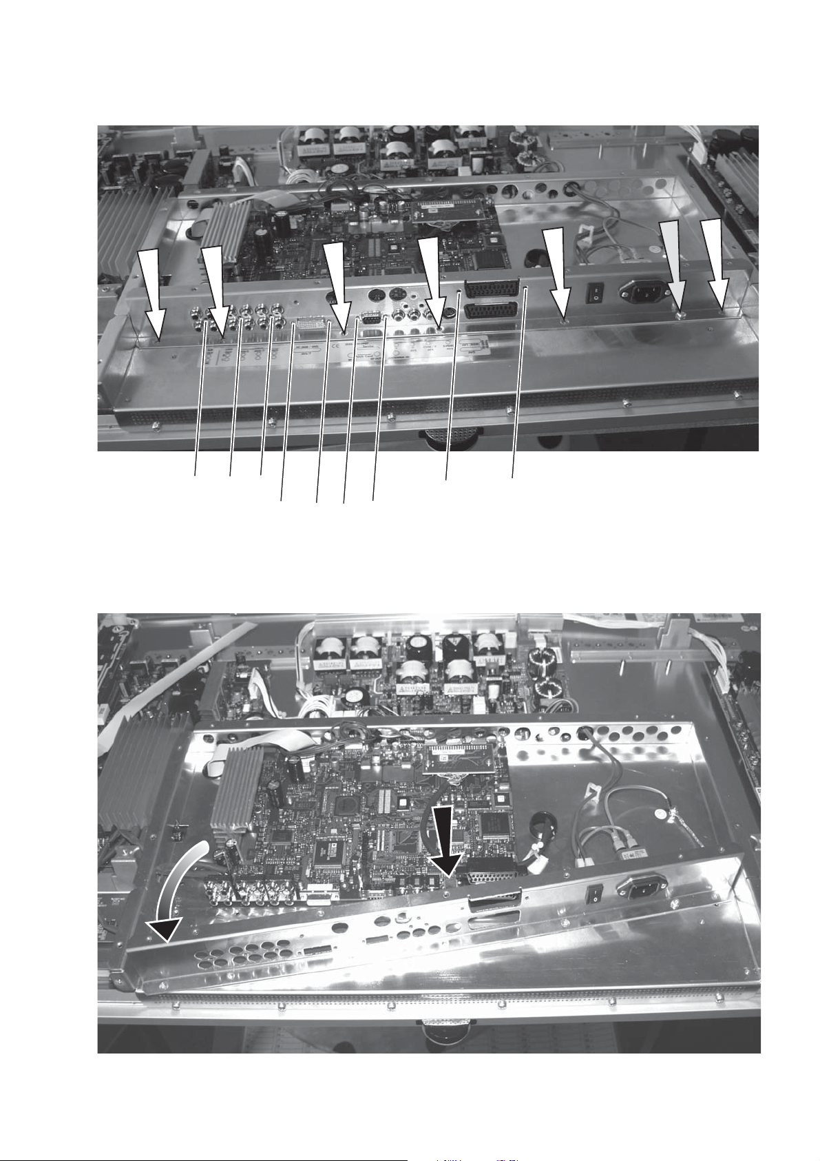
Abb. 3 / Fig. 3
b1
b2
b3
b4
b5
b6
B
a1 a2 a3
Abb. 4 / Fig. 4
a4
a5
a6
a7
a8
1
a9
9
Page 62
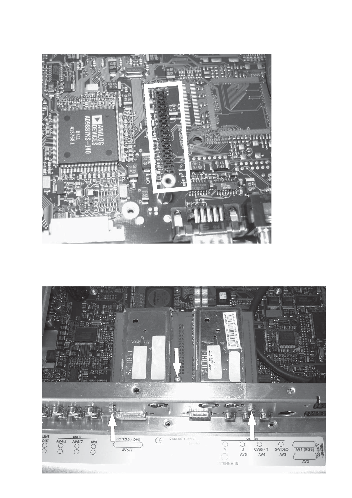
Abb. 5 / Fig. 5
Abb. 6 / Fig. 6
2
1
3
10
Page 63
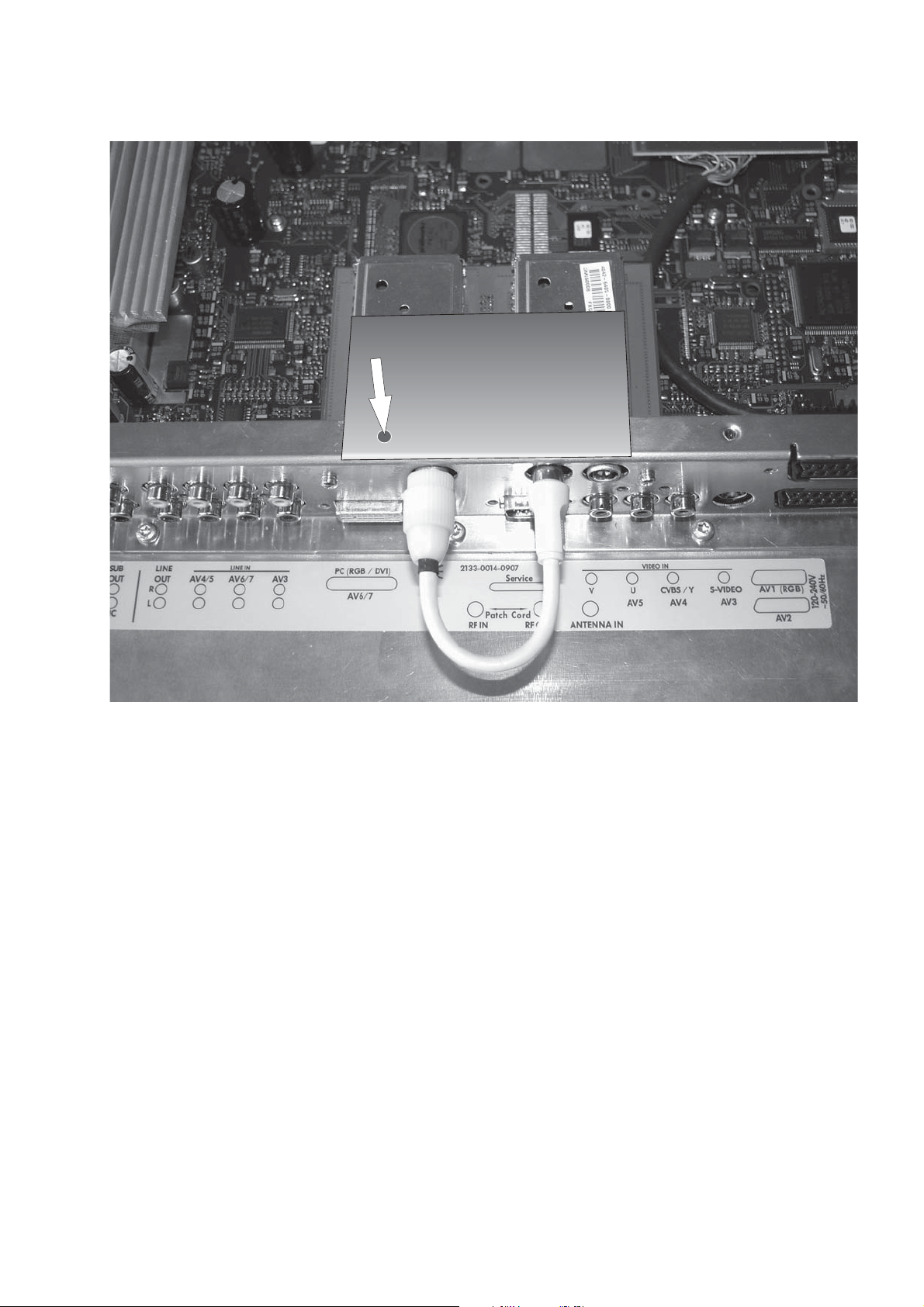
Abb. 7 / Fig. 7
11
Page 64

Loewe Opta GmbH
Postfach 1554
Industriestraße 1
D-96317 Kronach
Telefon (09261) 99-0
Telefax (09261) 95411
Hotline-Telefon (0180)5221801
e-mail: [email protected]
http: //www.loewe.de
04 - 2005
240 - 32496 000
 Loading...