

Loctite EQ RB40 series, EQ RB40 400D, EQ RB40 200D, EQ RB40 300D, EQ RB40 500D Operation Manual
EQ RB40 BENCHTOP
D-ROBOTS
OPERATION MANUAL

Table of Contents
SECTION 1: INTRODUCTION .................................................................................... 3
1.1 I
1.2 S
NTRODUCTION ...................................................................................................... 4
AFETY PRECAUTIONS........................................................................................... 4
1.3 PACKAGE CONTENTS............................................................................................. 5
1.4 CONNECTOR AND SWITCH LOCATIONS .................................................................... 6
SECTION 2: MACHINE SETUP .................................................................................. 11
2.1 UNPACKING THE ROBOT ........................................................................................ 12
2.2 SETUP .................................................................................................................. 12
SECTION 3: EQUIPMENT OPERATION .................................................................... 13
3.1 USING THE TEACH PENDANT .................................................................................. 14
3.2 CHANGING THE PROGRAM NUMBER ........................................................................ 17
3.3 CHANGING FROM TEACH MODE TO RUN MODE ........................................................ 17
SECTION 4: BASIC ERROR MESSAGES AND RESOLUTION ................................ 18
4.1 Point Closed Error ..............................................................................................................................19
4.2 Need Line Start Point ...........................................................................................................................19
4.3 Need Step & Repeat .............................................................................................................................19
4.4 Unlock Program ..................................................................................................................................19
4.5 Address Over Memory .........................................................................................................................20
4.6 Move Over Memory .............................................................................................................................20
4.7 System Error ........................................................................................................................................20
4.8 Over Speed Error .................................................................................................................................20
SECTION 5: SPECIFICATIONS .................................................................................. 21
5.1 I/O SPECIFICATIONS .............................................................................................. 22
5.2 SYSTEM SPECIFICATIONS ....................................................................................... 29
5.3 MACHINE DIMENSIONS ........................................................................................... 30
SECTION 6: MAINTENANCE, ACCESSORIES & SPARE PART .............................. 36
6.1 M
AINTENANCE ...................................................................................................... 37
6.2 ACCESSORIES & SPARE PARTS .............................................................................. 39
SECTION 7: EQUIPMENT WARRANTY ..................................................................... 40
7.1 E
SECTION
QUIPMENT WARRANTY ......................................................................................... 41
8: EC DECLARATION .................................................................................... 42
- Page 2 -

SECTION 1: Introduction
- Page 3 -

1.1 Introduction
Welcome to the Henkel Benchtop Robots operation manual, this manual is an instructional
guide designed for system operators, technicians and engineers. It provides a complete
tour for how to operate the Henkel Benchtop Robot.
Please check the Henkel Benchtop Robot software manual xxxxxx if you need instructions
for how to program.
1.2 Safety Precautions
In order to meet the requirements of the European Community (CE) safety
directives, the robot must be placed in an enclosure1 supplied by Henkel.
1.1 Make sure the robot is connected to a properly grounded power source before
operating.
1.2 Keep away from any moving parts while the robot is running.
1.3 Loading and unloading of parts and material must only be done when the robot is at a
complete stop.
1.4 Changing of fixtures or tooling must be done with the power source disconnected.
1.5 The robots should only be operated in an environment between 0 and 40 degrees
Celsius with humidity of 20 to 95 percent and no visible condensation.
1.6 Do not store or setup the robot in an area where it is directly exposed to sunlight.
1.7 Do not operate the robot where electrical noise is present.
1.8 Only use a neutral chemical for cleaning the robot. Do not use alcohol, benzene or
thinner as it may damage the paint on the robot.
1
The light curtain enclosure or safety door enclosure will prevent the operator from entering the robot’s work
area and will generate an emergency stop signal if the light curtain is interrupted or the enclosure’s door
switch is opened while the robot is running.
- Page 4 -

1.3 Package Contents
In addition to this operating manual, the following items should be included with the robot:
1. Main Unit (200D/300D/400D/500D)
2. Syringe Holder, 30-55ml, Fixed
3. External Control Shorted Connector
4. Dispensing Cable
5. Mounting Screw for Syringe Holder
6. Power Cord
7. USB memory stick
- Page 5 -
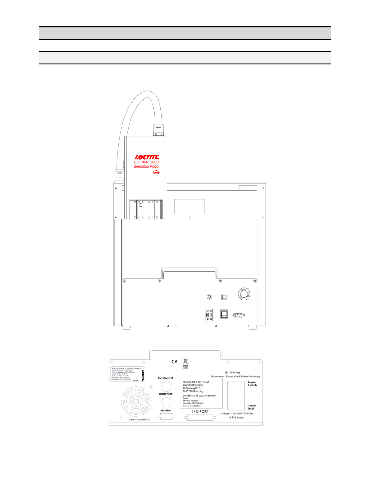
1.4 Connector and Switch Locations
1.4.1 200D
Front View
Rear View
- Page 6 -
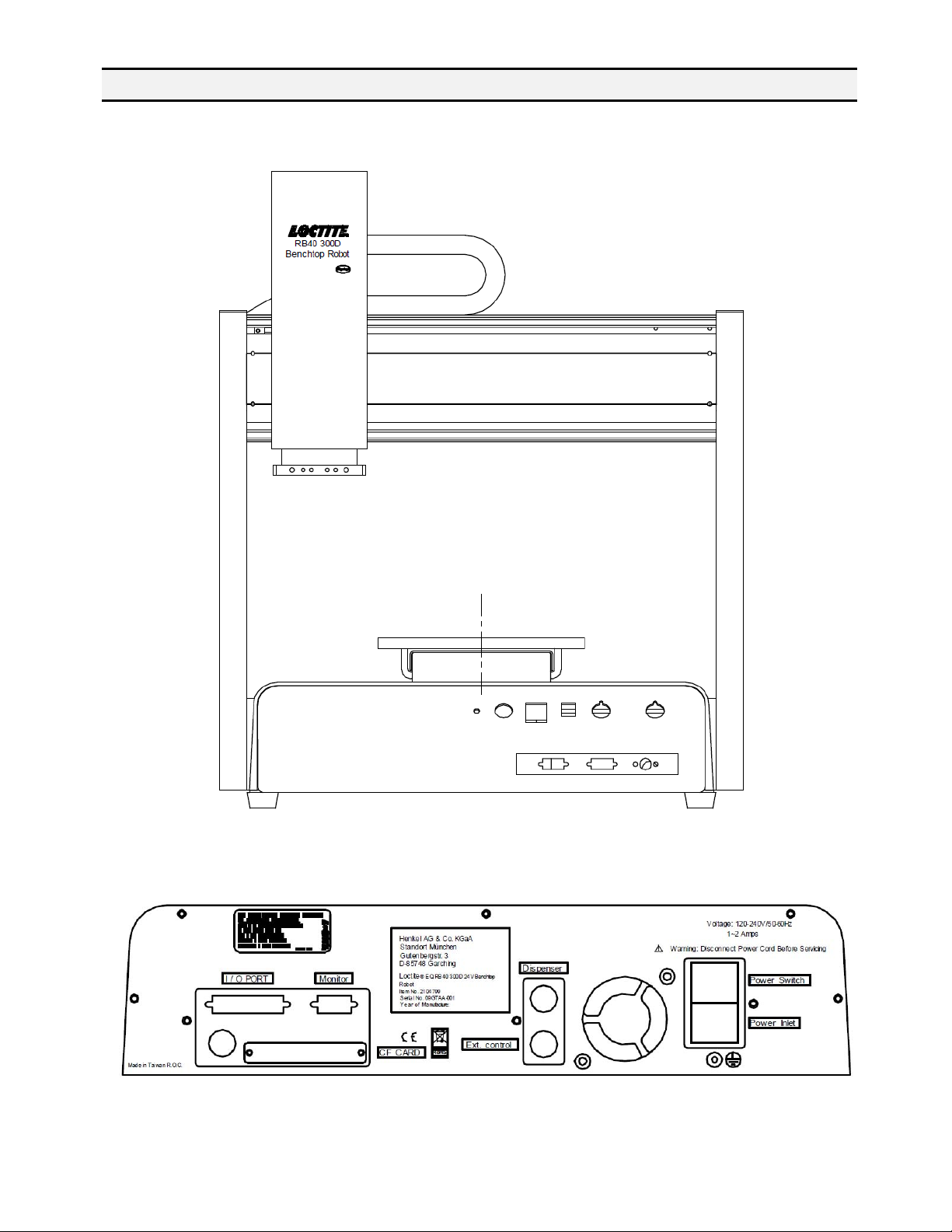
1.4.2 300D
Front View
Rear view
- Page 7 -
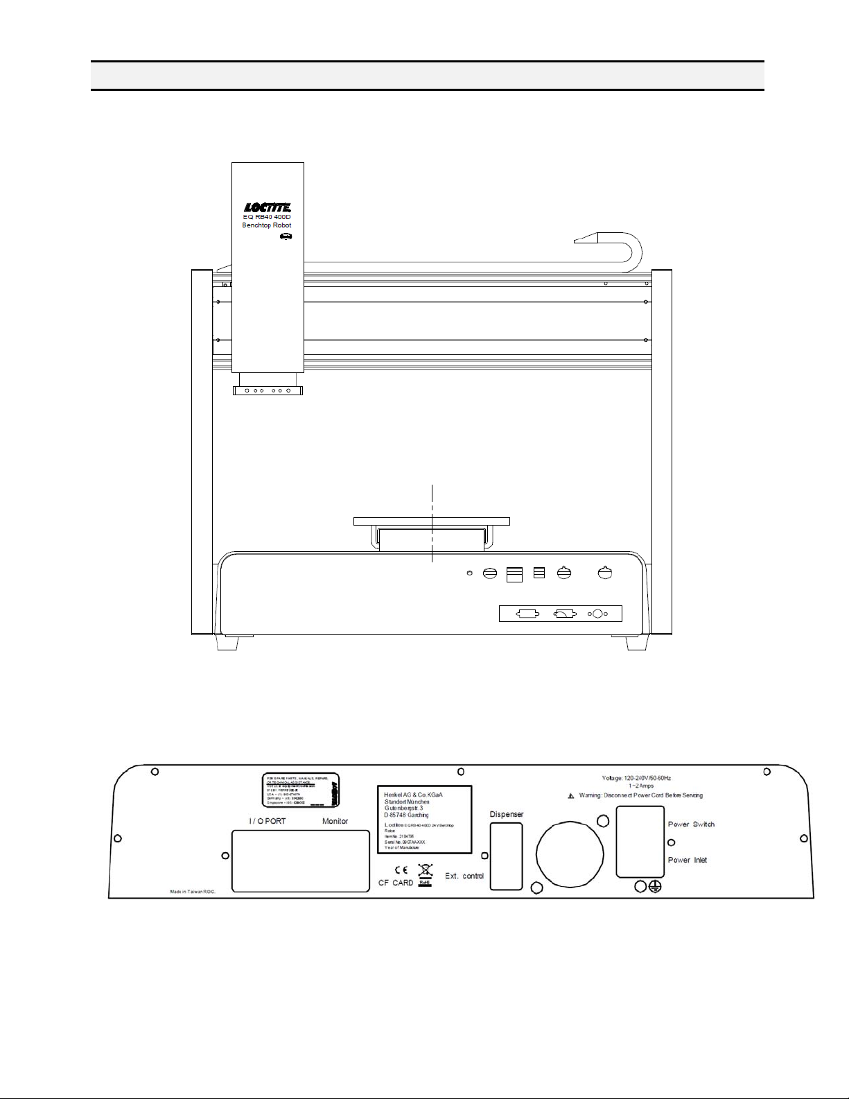
1.4.3 400D
Front View
Rear View
- Page 8 -
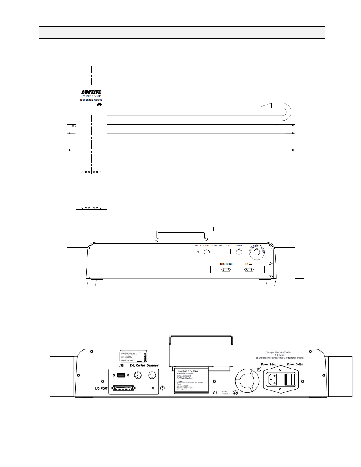
1.4.4 500D
Front View
Rear View
- Page 9 -


SECTION 2: Machine Setup
- Page 11 -

2.1 Unpacking the Robot
• Always lift the robot from its base. Never lift the robot from the cross member.
• Remove all accessories from the shipping package before attempting to remove the
robot.
• Place the robot on a stable workbench before operating.
If you can, do not discard the packing material as these items may be needed if the robot
is shipped or moved in the future.
2.2 Setup
The robots are available with different configurations. The setup of each machine with its
accessories will depend on the customer’s application.
1. Connect the external start / stop box and door switch or light curtain to the External
Control connector on the main unit. For further information, see SECTION 5.1.2:
External Control Connector.
If an enclosure is NOT being used, the enclosure door switch may be bypassed b y
connecting the plug labeled SHORTED (included in the robot accessories box) to
the External Control Connector.
2. Remove the shipping bracket2 by removing the screws that secure it. Keep the
shipping bracket and screws in a safe place for future use.
3. Connect one end of the Teach Pendant cable to the Teach Pendant and the other
end to the Teach Pendant connection on the robot.
4. Connect the power cord of the robot to the power socket on the robot. Be sure to
use the correct power cord and power source for the robot model you are using
(110 V or 220 V).
5. Tie back all cables and air lines s o that they will not interfere with the robot’s motion
when the robot is operating. Be sure that the cables and air lines do not restrict the
motion of the robot’s head and the robot’s table and make sure that they can not
become jammed as the robot moves through the work area.
2
The robots are shipped from the factory with a shipping bracket installed. The shipping bracket secures the
worktable to the X/Z head to prevent movement and damage during shipment.
- Page 12 -

SECTION 3: Equipment Operation
- Page 13 -
 Loading...