

Loctite EQ RB20 500D Operation Manual
Operation Manual
Equipment
Operation Manual
Loctite® EQ RB20 500D Dual Robot
Part Number: 2112252

Operation Manual
Table of Contents
SECTION 1: INTRODUCTION ................................................................................... 5
1.1 Please Observe the Following .............................................................................................................6
1.1.1 Em phasized Sections ............................................................................................................................6
1.1.2 For Your Safety ....................................................................................................................................6
1.1.3 Safety Precaution .................................................................................................................................7
1.2 Package Contents ................................................................................................................................7
SECTION 2: SETUP .................................................................................................... 8
2.1 Unpacking the Robot ...........................................................................................................................9
2.2 Setup ....................................................................................................................................................9
SECTION 3: TOUR OF ROBOT .................................................................................. 10
3.1 Robot Overview ...................................................................................................................................11
SECTION 4: TOUR OF TEACH PENDANT ................................................................ 12
4.1 Get Started ...........................................................................................................................................13
4.2 Teach Pendant Overview .....................................................................................................................15
4.3 Operation .............................................................................................................................................15
4.4 Key Introduction ..................................................................................................................................16
4.5 Navigation Menu .................................................................................................................................17
4.6 Jogging ................................................................................................................................................17
4.7 Data Entry ...........................................................................................................................................17
4.8 Running a Program .............................................................................................................................17
4.9 Teach Pendant Key Assignments .........................................................................................................18
SECTION 5: MENU INTRODUCTION ....................................................................... 21
5.1 F1 Menu ...............................................................................................................................................22
5.2 F2 Menu ...............................................................................................................................................25
5.2.1 Utility Menu .........................................................................................................................................26
5.3 F3 Menu ...............................................................................................................................................27
5.4 F4 Menu ...............................................................................................................................................28
SECTION 6: PROGRAMMING ................................................................................... 30
6.1 Before Program ...................................................................................................................................31
6.2 Programming Example ........................................................................................................................31
6.3 Good Programming Practices .............................................................................................................35
6.4 Editing a Program ...............................................................................................................................36
6.4.1 Changing a Point’s XYZ location ........................................................................................................36
6.4.2 Insert / Delete an Instruction ...............................................................................................................37
6.5 Changing the Program Number ...........................................................................................................38
6.6 Changing from Teach Mode to Run Mode ...........................................................................................38
6.7 Double Table Run Mode ......................................................................................................................38
SECTION 7: FUNCTION REFERENCE ...................................................................... 39
7.1 F1 Menu (Enter or F1 Key) .................................................................................................................40
7.1.1 Dispense Dot ........................................................................................................................................40
7.1.2 Line Start .............................................................................................................................................40
7.1.3 Line Passing.........................................................................................................................................41
7.1.4 Circle ...................................................................................................................................................41
7.1.5 Arc Point ..............................................................................................................................................42
7.1.6 Line End ...............................................................................................................................................42
7.1.7 End Program .......................................................................................................................................42
7.1.8 Dispense ON / OFF .............................................................................................................................43
7.1.9 GOTO Address .....................................................................................................................................44
7.1.10 Step & Repeat X ...................................................................................................................................44
7.1.11 Step & Repeat Y ...................................................................................................................................49
7.1.12 Brush Area ...........................................................................................................................................50
7.1.12.1 Brush Area: Rectangle .........................................................................................................................51
7.1.12.2 Brush Area: Circle ...............................................................................................................................52
7.1.12.3 Brush Area: Rectangle 1 ......................................................................................................................53
7.1.12.4 Brush Area: Rect. Band .......................................................................................................................54
- Page 2 -

Operation Manual
7.1.12.5
Brush Area: Circle Band .....................................................................................................................55
7.1.12.6 Brush Area: Circle 1 ............................................................................................................................56
7.1.12.7 Call Subroutine ....................................................................................................................................57
7.1.13 Call Program .......................................................................................................................................58
7.1.14 Set I/O ..................................................................................................................................................58
7.1.15 Wait Point ............................................................................................................................................59
7.1.16 Stop Point ............................................................................................................................................59
7.1.17 Home Point ..........................................................................................................................................59
7.1.18 Loop Address .......................................................................................................................................59
7.1.19 Dummy Point .......................................................................................................................................60
7.1.20 Initialize ...............................................................................................................................................60
7.1.21 Label ....................................................................................................................................................60
7.1.22 Display Counter ...................................................................................................................................60
7.1.23 Loop Counter .......................................................................................................................................60
7.1.24 Needle Adjustment ...............................................................................................................................61
7.1.25 Needle Adjustment Counter .................................................................................................................61
7.1.26 Arc Dispense Setup ..............................................................................................................................62
7.1.27 Double Table Switch ............................................................................................................................63
7.2 F2 Menu (F2 Key) ...............................................................................................................................63
7.2.1 Group E dit ...........................................................................................................................................63
7.2.1.1 Copy .....................................................................................................................................................63
7.2.1.2 Delete ...................................................................................................................................................65
7.2.1.3 Move ....................................................................................................................................................66
7.2.1.4 Line SP (Line Speed) ............................................................................................................................67
7.2.1.5 Dispense Time ......................................................................................................................................68
7.2.1.6 Offset ....................................................................................................................................................69
7.2.1.7 Offset (R.E) ..........................................................................................................................................70
7.2.2 Expand Step & Repeat .........................................................................................................................71
7.2.3 Program Name .....................................................................................................................................72
7.2.4 Z-axis Limit (mm) ................................................................................................................................72
7.2.5 Initial Output Port ...............................................................................................................................72
7.2.6 Utility Menu .........................................................................................................................................73
7.2.6.1 Program ...............................................................................................................................................73
7.2.6.2 Memory ................................................................................................................................................73
7.2.6.3 Teach Pendant .....................................................................................................................................74
7.2.6.4 Relocate Data ......................................................................................................................................74
7.2.6.5 Lock or Unlock Program .....................................................................................................................76
7.2.6.6 Password Setup ....................................................................................................................................76
7.2.6.7 Key Beep ..............................................................................................................................................76
7.2.6.8 Test Function .......................................................................................................................................76
7.2.6.9 Clear Teach Pendant Data ..................................................................................................................76
7.3 F3 Menu (F3 Key) ...............................................................................................................................77
7.3.1 Numerical Move ...................................................................................................................................77
7.3.2 Save Temp Point ..................................................................................................................................77
7.3.3 Move To Temp Point ............................................................................................................................77
7.3.4 Undo Program .....................................................................................................................................77
7.3.5 Redo Program ......................................................................................................................................77
7.3.6 Debug Program ...................................................................................................................................78
7.3.7 Move To Hom e Position ......................................................................................................................78
7.3.8 System Information ..............................................................................................................................78
7.3.9 Execute Point .......................................................................................................................................78
7.3.10 Program Name List ..............................................................................................................................78
7.4 F4 Menu (F4 Key) ...............................................................................................................................79
7.4.1 Line Speed ............................................................................................................................................79
7.4.2 Line Dispe nse Se tup .............................................................................................................................79
7.4.3 Point Dispe nse Setup ...........................................................................................................................80
7.4.4 Dispe nse End Setup .............................................................................................................................80
7.4.5 Z Clearance .........................................................................................................................................82
7.4.6 X/Y Move Speed ...................................................................................................................................83
7.4.7 Z Move Speed .......................................................................................................................................83
7.4.8 Home Position Setup ............................................................................................................................84
7.4.9 Adjust Position Setup ...........................................................................................................................85
7.4.10 Retract Setup ........................................................................................................................................87
7.4.11 Quickstep .............................................................................................................................................89
7.4.12 Auto Purge Setup .................................................................................................................................90
7.4.13 ESTOP Output Status...........................................................................................................................90
7.4.14 Acceleration .........................................................................................................................................91
7.4.15 Pause Status .........................................................................................................................................91
7.4.16 Language .............................................................................................................................................91
7.4.17 Jog Speed .............................................................................................................................................91
7.4.18 Debug Speed ........................................................................................................................................91
7.4.19 Adjust Origin .......................................................................................................................................92
- Page 3 -

Operation Manual
7.4.20
Quickstep Path .....................................................................................................................................92
7.4.21 USB Up/Down Load ............................................................................................................................92
7.4.22 Circle Delay Time ................................................................................................................................94
7.4.23 Initialize Setup .....................................................................................................................................94
7.4.24 Teach Needle Adjustment .....................................................................................................................95
7.4.25 Teach Needle Adjustment Setup ...........................................................................................................96
7.4.26 Double Table Run Mode ......................................................................................................................97
SECTION 8: SAMPLE PROGRAMS ........................................................................... 98
8.1 Dots, Lines and Arcs ............................................................................................................................99
8.2 Brush Area ...........................................................................................................................................101
8.3 Step & Repeat ......................................................................................................................................102
8.4 Input / Output Signal Processing .........................................................................................................104
8.5 Needle Calibration ...............................................................................................................................106
SECTION 9: SOFTWARE UPGRADE ......................................................................... 107
9.1 Check System Version ..........................................................................................................................108
9.2 Upgrade Software ................................................................................................................................108
SECTION 10: ERROR MESSAGES AND SPECIFICATIONS ...................................... 109
10.1 Point Closed Error ..............................................................................................................................110
10.1.1 Need Line Start Point ...........................................................................................................................110
10.1.2 Need Step & Repeat .............................................................................................................................110
10.1.3 Unlock Program ..................................................................................................................................110
10.1.4 Address Over Memory .........................................................................................................................111
10.1.5 Move Over Memory .............................................................................................................................111
10.1.6 System Error ........................................................................................................................................111
10.1.7 Over Speed Error .................................................................................................................................111
10.2 I/O Specification ..................................................................................................................................112
10.2.1 Dispenser Connector ...........................................................................................................................112
10.2.2 Ext. Control Connector ........................................................................................................................112
10.2.3 Output Signals .....................................................................................................................................113
10.2.4 Input Signal ..........................................................................................................................................115
10.2.5 Input/Output Schematic .......................................................................................................................116
10.2.6 Input/Output Power Specifications ......................................................................................................116
10.3 System Specifications ...........................................................................................................................117
10.4 Machine Dimensions............................................................................................................................118
SECTION 11: MAINTENANCE ACCESSORIES & SPARE PARTS ............................. 119
11.1 Maintenance ........................................................................................................................................120
11.1.1 General Consideration ........................................................................................................................120
11.1.2 Check Cycles &Points .........................................................................................................................120
11.1.3 Check Methods .....................................................................................................................................121
11.2 Accessories & Spare Parts ..................................................................................................................122
SECTION 12: EQUIPMENT WARRANTY ................................................................... 124
12.1 Equipment Warranty ............................................................................................................................125
- Page 4 -

Operating Manual
SECTION 1: Introduction
- Page 5 -
Operating Manual
1.1 Please Observe the Following
1.1.1 Emphasized Sections
WARNING!
Refers to safety regulations and required measures that protect the operator or other persons
from injury or danger to life.
Caution!
Emphasizes what must be done or avoided so that the unit or other property is not damaged.
Notice:
Gives recommendations for better handling of the unit during operation or adjustment, as
well as for service activities.
1.1.2 For Your Safety
For safe and successful operation of the unit, read these instructions completely. If the
instructions are not observed, the manufacturer can assume no responsibility. Be sure to
retain this manual for future reference.
WARNING!
Always wear temperature resistance gloves before touch the housing of dispensing head or
pre heater.
WARNING!
Never remove the cover of the unit without first switching the power off and unplugging the
power cord.
WARNING!
Damage to the power cord or the housing can result in contact with live electrical parts.
Check the power cord and housing before each use. If the power cord or unit is damaged, do
not operate.
The unit may be repaired only by a Loctite® authorized service technician.
- Page 6 -

Operating Manual
1.1.3 Safety Precaution
In order to meet the requirements of the European Community (CE) safety directives, the
robot must be placed in an enclosure1 supplied by Henkel.
• Make sure the robot is connected to a properly grounded power source before operating.
• Keep away from any moving parts while the robot is running.
• Loading and unloading of parts and material must only be done when the robot is at a
complete stop.
• Changing of fixtures or tooling must be done with the power source disconnected.
• The RB20 500D Dual Benchtop Robot should only be operated in an environment between
10 and 40 degrees Celsius with humidity of 20 to 95 percent and no visible condensation.
• Do not store or setup the robot in an area where it is directly exposed to sunlight.
• Do not operate the robot where electrical noise is present.
• Only use a neutral chemical for cleaning the robot. Do not use alcohol, benzene or thinner as
it may damage the paint on the robot.
1.2 Package Contents
In addition to this operating manual, the following items should be included with the robot.
1. RB20 500D Dual Robot
2. Dispense Cable (3 to 9 pin)
3. Teach Pendant Cable (9 pin to 9pin)
4. Syringe Holder
5. Shortage 7-pin
6. Power Cord
7. Screws for Syringe Holder
8. USB Memory Stick
9. The Robot Needle Calibration Kit
- Page 7 -

Operating Manual
SECTION 2: Setup
- Page 8 -

Operating Manual
2.1 Unpacking the Robot
• Always lift the robot from its base. Never lift the robot from the cross member.
• Remove all accessories from the shipping package before attempting to remove the robot.
• Place the robot on a stable workbench before operating
If you can, do not discard the packing material as these items may be needed if the robot is shipped
or moved in the future.
2.2 Setup
• Remove the shipping bracket by removing the screws that secure it. Keep the shipping
bracket and screws in a safe place for future use.
• Connect one end of the Teach Pendant cable to the Teach Pendant and the other end to the
Teach Pendant connection on the robot.
• Connect the power cord of the robot to the power socket on the robot. Be sure to use the
correct power cord and power source for the robot model you are using (220 V).
• Tie back all cables and air lines so that they will not interfere with the robot’s motion when
the robot is operating. Be sure that the cables and air lines do not restrict the motion of the
robot’s head and the robot’s table and make sure that they cannot become jammed as the
robot moves through the work area.
- Page 9 -

Operating Manual
SECTION 3: Tour of Robot
- Page 10 -
Operating Manual
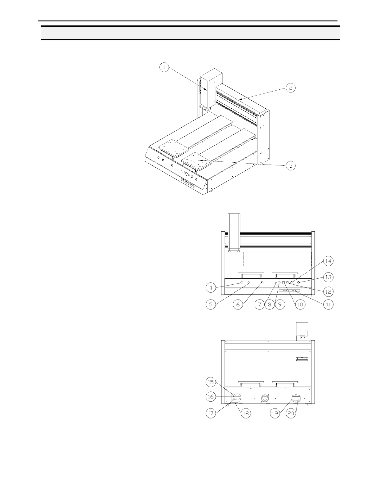
3.1 Robot Overview
1. Z-Axis
2. X-Axis
3. Y-Axis
4. START Button
5. START Button(Left Table)
(Use with START Button)
6. Table Left/Right Switch
7. Power Indicator
8. Purge Button
9. Teach Pendant Connector
10. PROG. No.
11. RS 232
12. RUN/TEACH Mode Switch
13. EMO (Emergency Stop)
14. START Button(Right Table)
(Use with START Button)
15. External Control Port
16. Dispenser Control Port
17. USB Port
18. I/O Port
19. Power Inlet
20. Power Switch
- Page 11 -

Operating Manual
SECTION 4: Tour of Teach Pendant
- Page 12 -
Operating Manual
4.1 Get Started
A program consists of a series of instructions stored in the main memory unit. Each instruction is
stored in a numbered memory address. A memory address may record a point location with an X,
Y1,Y2 and Z-axis value and point type or it may store an instruction, which sets a parameter, such
as a dispensing time or line speed.
When the program is executed, the robot will go through each memory address in sequence and
execute the instruction found there. If the memory address contains a point location, the robot will
move the X, Y1,Y2 and Z axes to that location. Depending on the type of point registered at that
location, the robot may also perform other functions, such as turn the dispenser on or off.
The most commonly used point types are Dispense Dot, Line Start, Line Passing, Arc Point, and
Line End.
To program the robot to dispense a ‘dot’ of material, the dispensing tip must be jogged to the
desired XYZ location, then that location is registered as a DISPENSE DOT point type by pressing
the appropriate keys on the Teach Pendant.
Dispense Dot
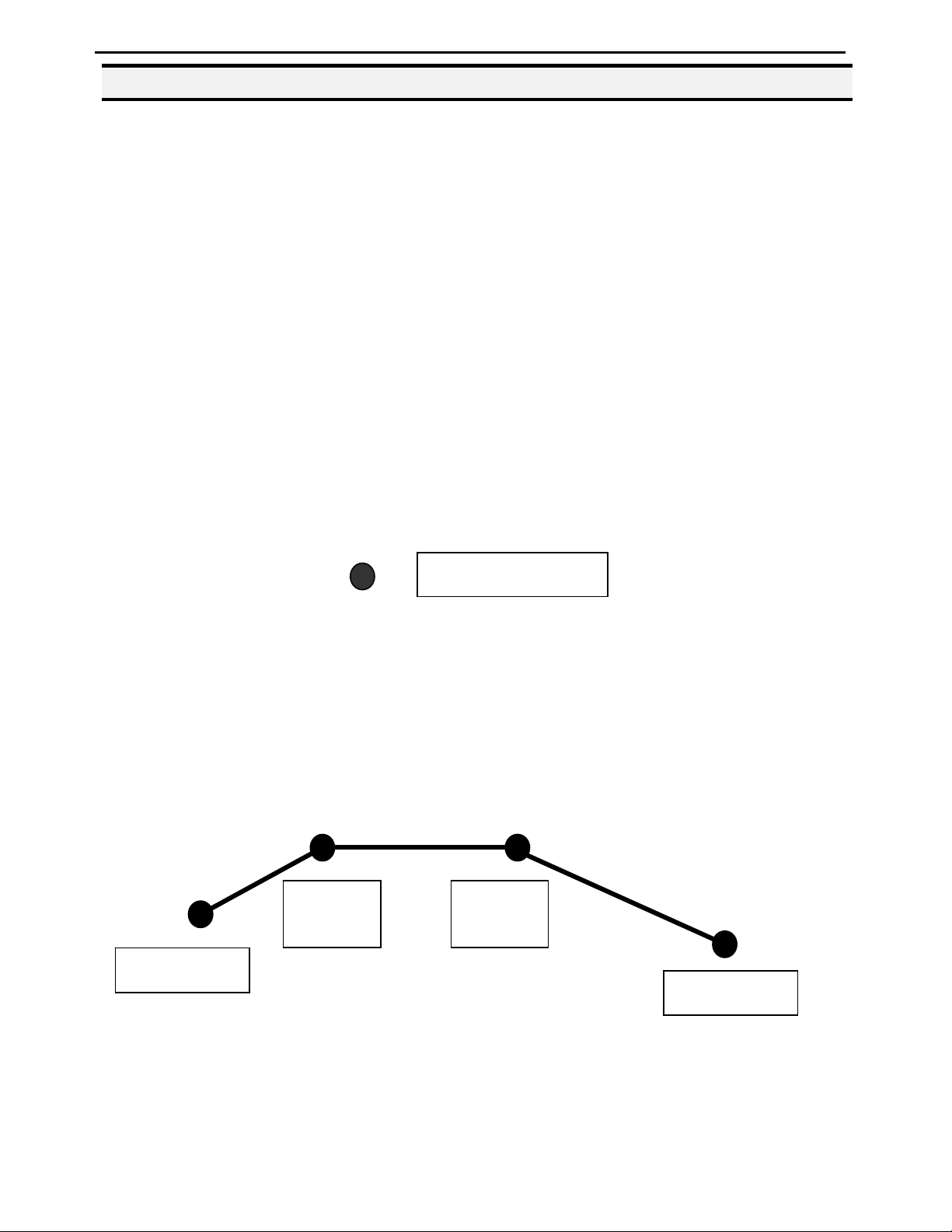
To program the robot to dispense a bead of material along a linear path, the XYZ location of the
start of the line is registered as a LINE START point type. The locations where the tip changes
direction are registered as LINE PASSING points. The end of the line is registered as a LINE END
point:
The LINE START has already included DISPENSE ON function and the LINE END has already
included DISPENSE OFF function.
Line
Passing
Line
Passing
Line Start
Line End
- Page 13 -

Operating Manual
To dispense a bead of material in an arc, the XYZ location of the start of the line is registered as a
LINE START point type. The high point of the arc is registered as an ARC POINT. The end of the
arc is registered as a LINE END point:
Arc Point
Line Start Line End
Lines and arcs can also be combined to dispense a bead of material along a complex path: You
cannot have 2 consecutive arc points in a program.
Arc Point
Line Passing
Line Passing
Arc Point
Line End
Line Start
Once the required point locations for your program have been taught, the teach pendant is no longer
required. The unit can be switched to RUN mode and operated using the buttons and switches on
the main unit control panel.
- Page 14 -

Operating Manual
4.2 Teach Pendant Overview
The teach pendant enables the user to jog the robot to input program data.
4.3 Operation
There are several functions assigned to most keys on the Teach pendant. When a key is pressed
alone, the function shown in the dark grey colored area on the key is executed. For example, Ins,
Del, Jump, Clear and Esc are the default key functions, which are executed when that key is
pressed alone.
To access the function shown in the light grey area at the top of a key, press and release the Shift
key first (the LED on the Shift key will be flashing), then press the desired key. For example, to
select the Speed function, press and release Shift, then press the Speed key.
When a number is required, the teach pendant will automatically switch to numeric entry mode.
The number represented by each key is shown in the lower right corner of the key.
- Page 15 -
Operating Manual
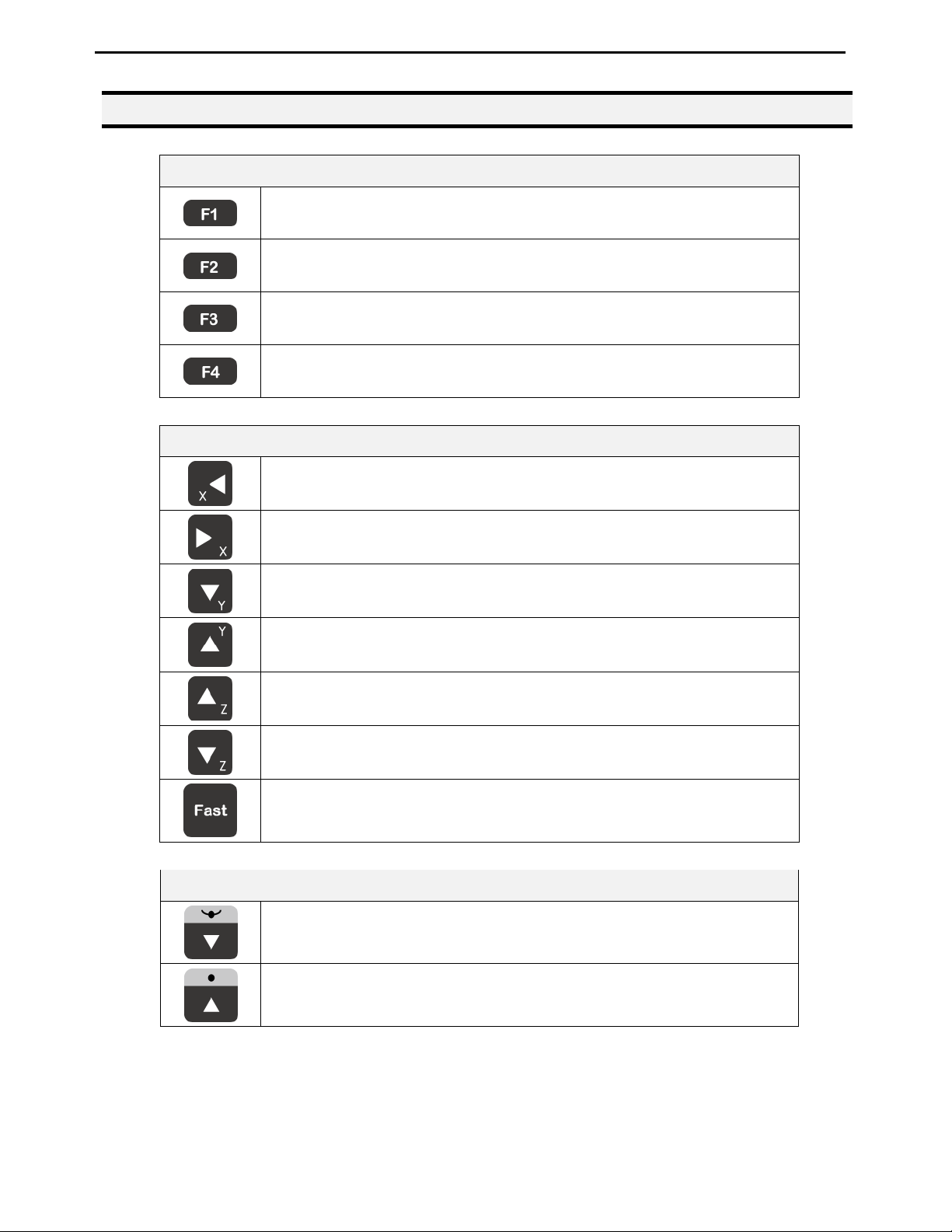
4.4 Key Introduction
Opens the Point registration menu.
Select the options shown on the display.
Opens F2 Menu.
Select the options shown on the display.
Opens F3 Menu.
Select the options shown on the display.
Opens the F4 Setup menu.
Select the options shown on the display.
Menu Keys
Jog Keys
Jogs the X-axis in the left direction.
Jogs the X-axis in the right direction.
Jogs the Y-axis in the backward direction.
Jogs the Y-axis in the forward direction.
Jogs the Z-axis UP.
Jogs the Z-axis DOWN.
Accelerates jog speed – used with X+, X-. Y+, Y-, Z Up, Z Down.
Navigation Display
Moves forward (1) memory address.
Moves backward (1) memory address.
- Page 16 -
Operating Manual
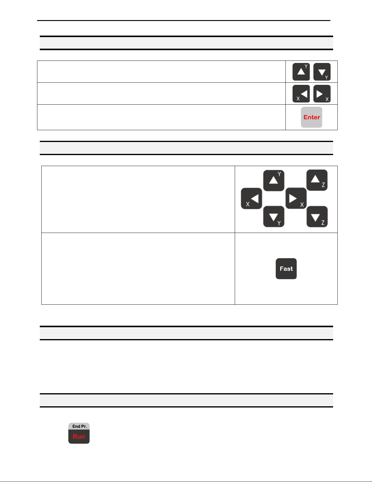
4.5 Navigation Menu
Once the menu is open, use the up and down arrows to move through the items on
the menu.
Use left and right arrows to change to the next page or previous page of the menu.
Press ENTER to select the current item.
4.6 Jogging
The tip is jogged by pressing the jog buttons.
If the FAST button is pressed and held first, then one of the j og
buttons is pressed, the axis will be jogged at the maximum jog
speed.
If one of the jog buttons is pressed first, then the FAST button
is pressed, the jog motion will accelerate.
If the FAST button is released, the jog motion will decelerate.
4.7 Data Entry
If a numeric value is required, the teach pendant will automatically switch to numeric mode. Use
the keys 0 – 9, (.) and the minus sign (-) to enter numbers.
4.8 Running a Program
Press the
- Page 17 -
key to run the program.
Operating Manual
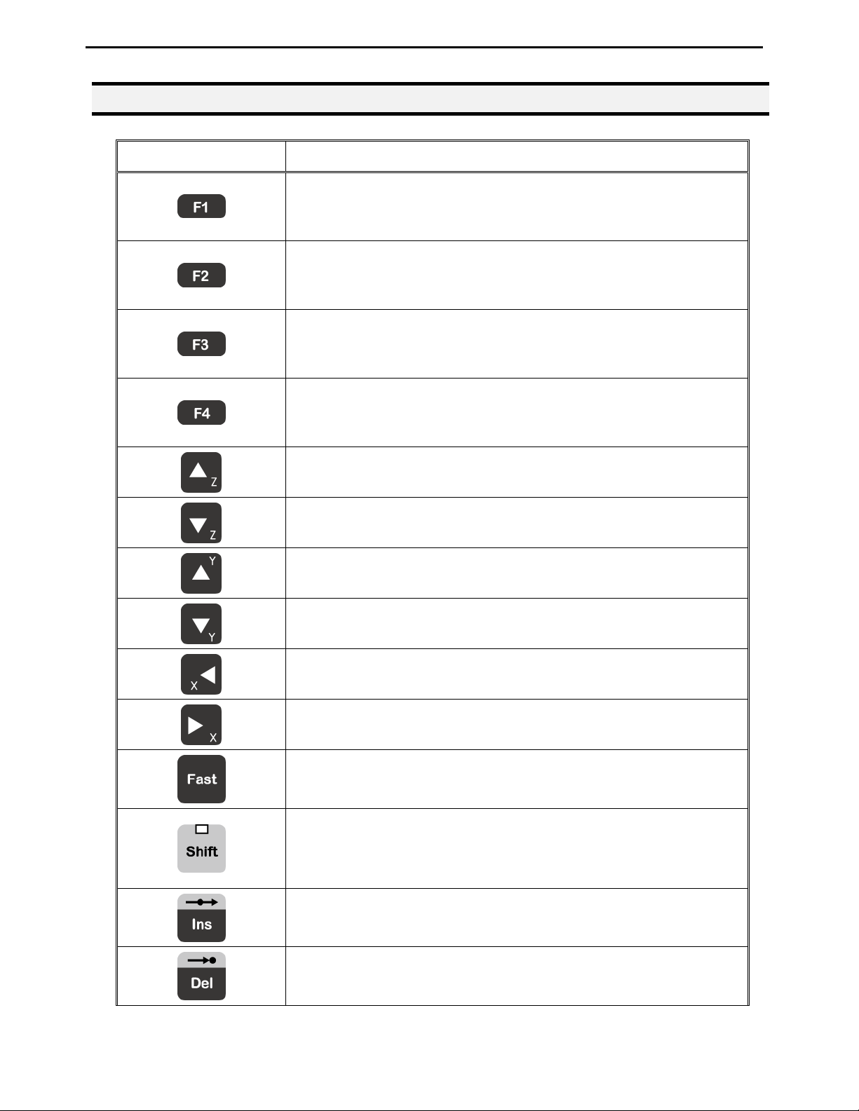
4.9 Teach Pendant Key Assignments
Key Function
Opens the F1 Point registration menu.
Used to select options shown on the display.
The use of this key depends on the current menu displayed.
Opens the F2 Menu.
Used to select options shown on the display.
The use of this key depends on the current menu displayed.
Opens the F3 Menu.
Used to select options shown on the display.
The use of this key depends on the current menu displayed.
Opens the F4 Setup Menu.
Used to select options shown on the display.
The use of this key depends on the current menu displayed.
Jogs the Z-axis UP.
Jogs the Z-axis DOWN.
Jogs the Y-axis in the forward direction.
Jogs the Y-axis in the backward direction.
Jogs the X-axis in the left direction.
Jogs the X-axis in the right direction.
Accelerates the jog speed when used with X+, X-. Y+, Y-, Z Up,
Z Down.
If Shift is pressed and released, then another key is pressed, the
secondary function of that key (shown in light grey) will be
executed.
Inserts a memory address before the current address.
Deletes the current memory address.
- Page 18 -
Operating Manual
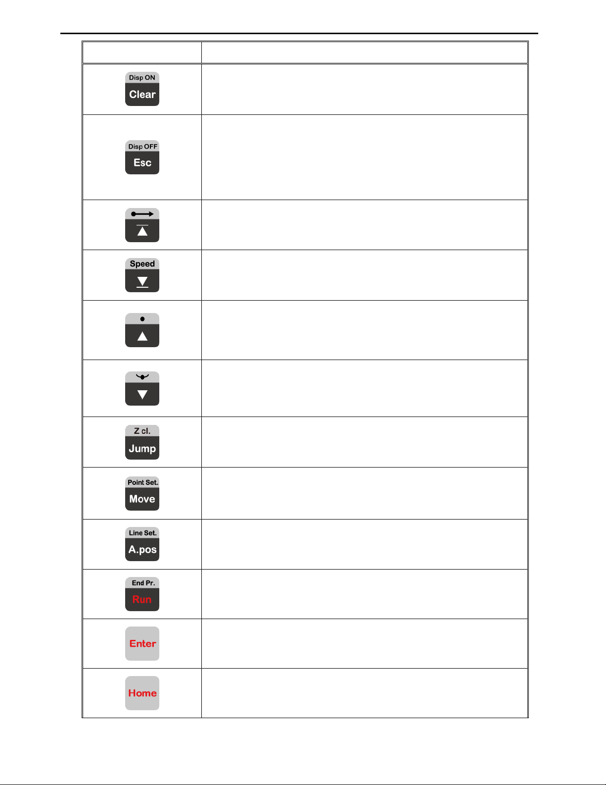
Key Function
Clears / erases the numeric value currently shown in the display.
If pressed once, clears the current numeric value.
If pressed twice, cancels the current function.
If a program is running, cancels the running program.
Changes from Point List display mode to Single Point display
when teaching point data.
Changes the display to memory address number 1.
Changes the display to the last memory address used in the
program.
Moves back (1) memory address.
After opening a menu, use this key to move Up inside the menu.
Moves forward (1) memory address.
After opening a menu, use this key to move Down inside the
menu.
Jumps to a specified memory address.
Moves the tip to the point location currently in the display.
Adjusts the tips position after a barrel change.
Runs the program.
(Enter)–used to confirm data entries.
Opens the Point registration menu.
Homes the robot. Initializes all axes and moves the head to the
- Page 19 -
position (0, 0, 0).
Operating Manual
Key Function
+
+
+
+
+
Registers a DISPENSE DOT point.
Registers a LINE START point.
Registers a LINE PASSING point.
Registers a LINE END point.
Registers an ARC POINT.
+
+
+
+
+
+
+
Registers a Point Dispense Setup command.
Registers a Line Dispense Setup command.
Registers a Line Speed command.
Registers the End Program command.
Registers a Z Clearance command.
Set the dispenser “Off”.
Set the dispenser “On”.
Dry Run Program.
+
- Page 20 -
The use of this key depends on the current menu displayed.
The use of this key depends on the current menu displayed.

Operating Manual
SECTION 5: MENU Introduction
- Page 21 -

Operating Manual
5.1 F1 Menu
Below is a list of Point Types, which are found under the Enter or F1 key (F1 Menu):
Function Description
Dispense Dot
Line Start
Line Passing
Circle
Arc Point
Line End
End Program
Dispense On / Off
Registers the current XYZ location as a Dispense point for dot
dispensing.
Registers the current XYZ location as a Line Start point for line
dispensing.
This function is also includes DISPENSE ON function.
Registers the current XYZ location as a Line Passing point. This is
a location on the line where the tip changes direction, such as at
the corner on a rectangle.
Registers a circle with the circle center at the current XYZ
location. The display will prompt the user for the circle diameter.
Registers the current XYZ location as an Arc point. Arc points are
used to dispense material in an arc or circle.
Registers the current XYZ location as a Line End point.
This function also includes DISPENSE OFF function.
Registers the current memory address as the end of the program.
Registers an instruction which turns the dispenser on or off at the
current XYZ location.
GOTO Address
Causes the program to jump to the specified memory address.
Registers an instruction that will re-run a selected group of
memory addresses, stepping by a user-defined distance in the X or
Y-axis after each copy. The matrix of parts is defined by specifying
the number of rows, the number of columns, the X offset and the Y
Step & Repeat
offset.
Step & Repeat X indicates that the robot will give priority to the
X-axis, running the parts along the X-axis first.
Step & Repeat Y indicates that the robot will give priority to the Yaxis, running the parts along the Y-axis first.
- Page 22 -

Operating Manual
Function Description
Brush Area
Call Subroutine
Call Program
Set I/O
Wait Point
Stop Point
Home Point
Causes the tip to ‘paint’ the defined area. The painted area can be
in the form of a rectangle or a circle / spiral.
Causes the machine to jump to a specified memory address and
execute the instructions found there. When the end program
instruction is reached, program execution will continue at address
just after the call Subroutine instruction.
Jumps to the specified program number from within the current
program.
Registers an instruction, which either sets the value of an output
signal or checks the status of an input signal.
After executing the current point (Line start, passing, etc) the robot
will wait a specified amount of time before moving to the next
command.
After executing the current point (Line start, passing, etc), the
robot will wait until the start button is pressed before moving to
the next command.
Registers an instruction to ‘home’ all axes, sending them to the
home position. See the F4 Menu for instructions on changing the
location of the home position.
Loop Address
Dummy Point
Initialize
Label
Display Counter
Loop Counter
Causes the program to execute a group of memory addresses a
user-specified number of times.
Registers the current XYZ location as a Dummy point. The tip will
simply pass through this point. Useful for avoiding obstacles on
the work piece.
Registers an Initialize point. Causes the robot to perform a
mechanical initialization.
Registers a label that can be used as a reference when used with
the GOTO address, Loop address, Set I/O, Step & repeat X, Step &
repeat Y and Call Subroutine commands.
Shows a counter at the bottom of the teach pendant screen while a
program is running.
To setup the “Loop Counter” to “Keep” or “Clear”.
- Page 23 -
Operating Manual
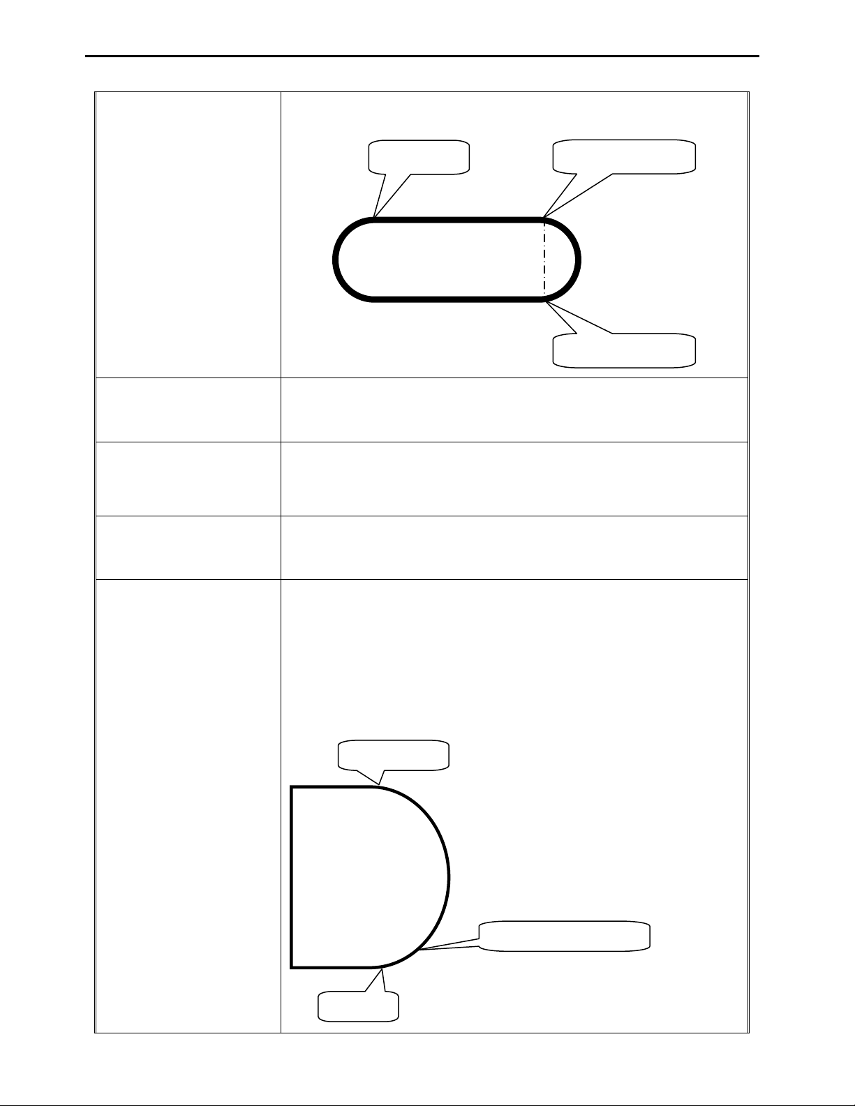
Registers the current memory address as the end of the “Stadium”
path setting:
Line Start
Line Passing
Line End 1
Dispense Output Setup
Needle Adjustment
Needle Adjustment
Counter
1
2
3
Line End 1
Register the assigned output port (0 – 8) ON or OFF controlled by
LINE START and LINE END (same as dispenser port).
Register the “Needle Adjustment” command in the first address.
System will perform Needle calibration automatically before
Dispensing.
Set up needle adjustment counter numbers. When the number is
reached, the system performs needle calibration.
Set up valve on time for arc dispensing. The Tail Length is
fictional but it’s controlled by times.
Arc Dispense time can control valve pre-shut off during arc
dispensing. i.e. If dispense time for a complete arc needs 5 sec, and
set 4 sec in arc dispense time, the valve will pre-shut off 1 sec
before end point.
Arc Start
Arc Dispense Setup
Arc Dispense Time
Arc End
- Page 24 -

Operating Manual
Set GPIO
Double Table Switch
GPIO Configure
Select left/right table when programming
5.2 F2 Menu
Below is a list of functions, which are found under the F2 key (F2 Menu):
Function Description
Allows a function to be applied to a user-defined group of
Group Edit
Expand Step & Repeat
memory addresses. Functions include copy, delete, move,
multiply line speed, multiply dispense times, apply X Offset,
apply Y Offset, apply Z Offset.
Expands the memory address locations which would be
performed at a Step & Repeat instruction so individual
memory addresses of the repeated instructions can be edited.
Program Name
Z-axis Limit (mm)
Initial Output Port
Utility Menu
Allows the user to register a name for the current program
number.
Sets the MAXIMUM Z-axis value (the lowest tip position).
Once the Z-axis limit is set, the robot will prevent the tip
from jogging below the set location.
Sets the status of the output signals when the machine is
initialized.
Opens the Utility Menu. See 5.2.1 Utility Menu.
- Page 25 -

Operating Manual
5.2.1 Utility Menu
Below is a list of functions, which are found under F2 Menu -> Utility Menu:
Function Description
Program
Memory
Teach Pendant
Relocate Data
Lock Program
Password Setup
Key Beep
Opens the Program utility menu. Allows programs to be
copied, backed up, restored, or cleared.
Opens the Memory utility menu. Allows the robot memory
to be backed up, restored, or cleared.
Opens the Teach Pendant utility menu. Allows the current
program to be copied to the Teach Pendant for transferring
to another robot.
Allows the position of a program to be corrected using two
reference points. Corrects for X offset, Y offset and angle of
rotation.
Locks or unlocks a program to enable or disable program
editing.
Allows the password to be set or reset for the current
program. Protects the program from unauthorized editing.
Enabling Key Beep to produce a beep every time a key in
the Teach Pendant is touched.
Test Function
Testing the Robot Sensor, Panel Connector, Input Output
signal, Teach Pendant and Motor.
- Page 26 -

Operating Manual
5.3 F3 Menu
Below is a list of functions, which are found under the F3 key (F3 Menu):
Function Description
Numerical Move
Save Temp Point
Move To Temp Point
Undo Program
Redo Program
Debug Program
Move To Home Position
System Information
Execute Point
Allows the tip to be positioned numerically by entering a
number for the X, Y and Z values.
Saves the current XYZ position in a temporary memory area
numbered 1 – 9.
Retrieves a XYZ position, which was stored with Save Temp
Point.
Cancels the last change to the program. Returns to the
program state prior to the last change.
Restores the last change to the program, which was canceled
with Undo.
Runs the program in Debug mode starting at the current point
location.
Causes the tip to move to the home position. The default home
position is X=0, Y=0, Z=0.
Displays system information, including software version
number, work area size and control board version.
Runs a selected command.
Program Name List
Displays the program list with program number and program
name.
- Page 27 -

Operating Manual
5.4 F4 Menu
Below is a list of functions, which are found under the F4 key (F4 Menu):
Function Description
Registers the LINE SPEED used for all lines from the current
Line Speed
Line Dispense Setup
Point Dispense Setup
memory address forward until another Line Speed instruction
is found.
Registers the LINE DISPENSE SETUP values which sets
dispensing wait time at the start of lines (‘head’ time), wait
time at the passing points (‘Node’ time) and waiting time at
the end of lines (‘tail’ time). The registered values will be used
from the current memory address forward until another Line
Dispense Setup instruction is found.
Registers POINT DISPENSE SETUP values, which sets
dispensing time and waiting time at the end of dispensing
(‘tail’ time) for dots. The registered values will be used from
the current memory address forward until another POINT
DISPENSE SETUP instruction is found.
Dispense End Setup
Z Clearance
XY Move Speed
Z Move Speed
Home Position Setup
Function Description
Adjust Position Setup
Registers the height and speed the tip should raise at the end
of dispensing. The registered values will be used from the
current memory address forward until another DISPENSE
END SETUP instruction is found.
Registers the additional distance the tip should rise, beyond
the height set in Dispense End Setup, to allow obstacles to be
cleared as the tip moves from one figure to another. Values
will be used until another Z Clearance instruction is found.
Sets the movement speed of the X and Y axes when moving
from one figure to another in the program.
Sets the movement speed of the Z-axis when moving from
one figure to another in the program.
Changes the position the robot moves to at the end of a
program cycle.
Registers the current XYZ location as the Adjust Position.
This reference point can later be used to correct the program
location after the dispensing tip has been changed.
- Page 28 -

Operating Manual
Function Description
Retract Setup
Registers Retract values at the current XYZ location. Retract
causes the tip to move up and back over the dispensed bead
after line dispensing.
Quickstep
Auto Purge Setup
ESTOP Output Status
Acceleration
Pause Status
Language
Jog Speed
Debug Speed (mm/s)
Adjust Origin
Quickstep Path
Causes the robot to move very fast from one point to another
reducing the time of the dispensing cycle.
Automatically purges the system at the end of the program.
After receiving the emergency stop signal, ESTOP Output
Status can modify the status of all the outputs or leave them as
before receiving the emergency signal.
Parameter that controls the robot’s acceleration
Sets the position to which the tip moves after pressing the
Start button. The tip can go to the Home position or will stay
at the position where the Start button was pressed.
Opens MENU for selecting the Language.
Allows the user to set the tip jog speed for teach mode: Low,
Middle or High jog speed can be selected.
Sets the speed used when running in Debug mode.
See Section 7.4.9 “Adjust Position Setup”.
To setup the move up shape of Z-axis. “Triangle Shape” or
“Normal Shape” .
Need to use with function “Quickstep”.
USB Up/Down Load
Circle Delay Time
Initialize Setup
Upload and Download program files via USB port.
See Section 7.4.21
Set up dispensing delay time if used over angle at Circle
command.
Allow machine to perform HOMING at each cycle.
Allow the user to set up the location of needle calibration
Teach Needle Adjustment
tools.
See Section 7.4.24
Needle Adjustment Setup
Double Table Run Mode
Setup Needle calibration method and calibrate repeat times.
See Section 7.4.25
To define the run mode of dual-table.
See Section 7.4.26
- Page 29 -

Operating Manual
SECTION 6: Programming
- Page 30 -
 Loading...