

Loctite 2257357, EQ CL30 Operating Manual

1
2257357 EQ CL30 LED Quad Controller
Operating Manual

2
Table of Contents
1 Please Observe the Following ................................................................................................... 3
1.1 Emphasized Sections ........................................................................................................... 3
1.2 For Your Safety ..................................................................................................................... 3
1.3 Unpacking and Inspection .................................................................................................. 5
1.4 Packing List ........................................................................................................................... 5
1.5 Features ................................................................................................................................. 5
1.6 Usage ..................................................................................................................................... 6
2 Description ................................................................................................................................... 6
2.1 Theory of Operation .................................................................................................................. 6
2.2 Display, operating elements and connections ...................................................................... 7
3 Technical Data ............................................................................................................................. 8
4 Installation .................................................................................................................................... 9
4.1 Environmental and Operating Conditions .............................................................................. 9
4.2 Connecting the Unit .................................................................................................................. 9
5 Operation ...................................................................................................................................... 9
5.1 Electrical Connection ................................................................................................................ 9
5.2 Turn on the Unit ...................................................................................................................... 10
5.3 Main Page ................................................................................................................................ 10
5.4 Parameter Setting Page ......................................................................................................... 11
5.5 Language Selection page ....................................................................................................... 14
5.6 Control Operation Page .......................................................................................................... 15
6 Application Hints ....................................................................................................................... 15
7 Troubleshooting ......................................................................................................................... 15
8 Care and Maintenance ............................................................................................................. 15
9 Accessories and Spare Parts ................................................................................................... 15
10 Diagrams .................................................................................................................................... 17
3
11 Warranty ..................................................................................................................................... 19
12 Declaration of Conformity ........................................................................................................ 20
1 Please Observe the Following
1.1 Emphasized Sections
Warning!
Refers to safety regulations and requires safety measures that protect the operator
or other persons from injury or danger to life.
Caution!
Emphasizes what must be done or avoided so that the unit or other property is not
damaged.
Notice:
A notice gives recommendations for better handling of the unit during operation or
adjustment as well as for service activities.
1.2 For Your Safety
For safe and successful operation of the unit, read these instructions
completely. If the instructions are not observed, the manufacturer can assume no
responsibility.
Do not expose the connecting cable to heat, oil, or sharp edges.
Make sure the Unit stands stable and secure.
Use only original equipment replacement parts.
Always disconnect the power supply before servicing the unit.
Observe general safety regulations for the handling of chemicals such as
Loctite® adhesives and sealants. Observe the manufacturer’s instructions as stated
in the Safety Data Sheet.
While under warranty, the unit may be repaired only by an authorized Loctite
service representative.

4
WARNING!
It is the responsibility of the user to ensure that all devices being driven by the LED Flood
Controller are set-up in a safe manner.
‘
The manufacturer is in no way responsible for injuries or damage to persons or property
resulting from devices being driven by the LED Flood Controller.
For safe and successful operation of the unit, read these instructions completely. If the
instructions are not observed, the manufacturer can assume no responsibility.
Removing, bypassing or putting out of operation any of the safety devices can result in
radiation damage to persons and damage to the unit and is therefore prohibited!
Do not look directly at LED-UV light, or at LED-UV light reflected in a mirror or other
reflective surface. Doing so could cause eye damage.
Install the LED head in a way that humans are not exposed to LED-UV light.
Exposure could injure the skin or cause other injury.
If there is a risk of the LED-UV light being exposed to UV reflective light, place the product
inside a cover with proper reflectance and heat characteristics to block that reflected light.
When operating the controller, set up the system so that the path of the LED-UV light is not
at eye level.
It is strongly recommended to place a protective barrier around the product so that people
cannot approach it while it is operating.
Wear protective UV glasses and other protective clothing during operation.
Never operate this product in a manner not described in this manual. Doing so risks
exposure to LED UV light.

5
Damage to the power cord or the housing can result in contact with live electrical parts.
Check the power cord and the unit before each use. If the power cord or the unit is
damaged, do not operate! Replace a damaged power cord with a new one.
The unit may be opened and repaired only by authorized service personal.
1.3 Unpacking and Inspection
Carefully unpack the Loctite® CL30 LED Quad Controller and examine the items
contained in the carton. Inspect the unit for any damage that might have occurred in
transit. If such damage has occurred, notify the carrier immediately. Claims for
damage must be made by the consignee to the carrier and should be reported to the
manufacturer.
1.4 Packing List
1.4.1 CL30 LED Quad Controller x 1
1.4.2 Equipment Manual x 1
1.4.3 Power Cord x 1
1.5 Features
1.5.1 Capacity for up to four UV LED Heads.
1.5.2 Works with Loctite CL30 Flood Heads.
1.5.3 Touch screen HMI
1.5.4 3 running modes: Timer, Level and Advance.
1.5.5 3 languages available: English, Chinese and Japanese.
1.5.6 Friendly UI

6
1.6 Usage
The Loctite CL30 quad controller is used with the CL30 365nm, 380nm, and 405nm
LED flood heads for use with light cure products that cure when exposed to
ultraviolet and/or visible light. The system can be operated manually, operated with
the integrated timer, or controlled with an external switch. The system is designed
for intermittent or constant duty cycle.
2 Description
2.1 Theory of Operation
The CL30 LED Flood Controller provides electrical power to the LED’s through the
connecting cable (not included).
Indicator lights located on the front panel of the power supply provide visual confirmation
that the LED’s are in or out of their acceptable range. In the event of temperature fault the
power supply will automatically shut down to protect the LED array.
When the cure cycle is initiated, light is immediately irradiated at or near maximum intensity
from the LED’s.
The curing process begins when the adhesive is placed under the LED’s. The two primary
variables that control the curing process are the time of exposure and the strength of the
light (irradiance). For a given irradiance, the exposure time required to fully cure the
adhesive depends primarily on the properties of the adhesive and the optical properties of
the substrate that the light is transmitted through.
7
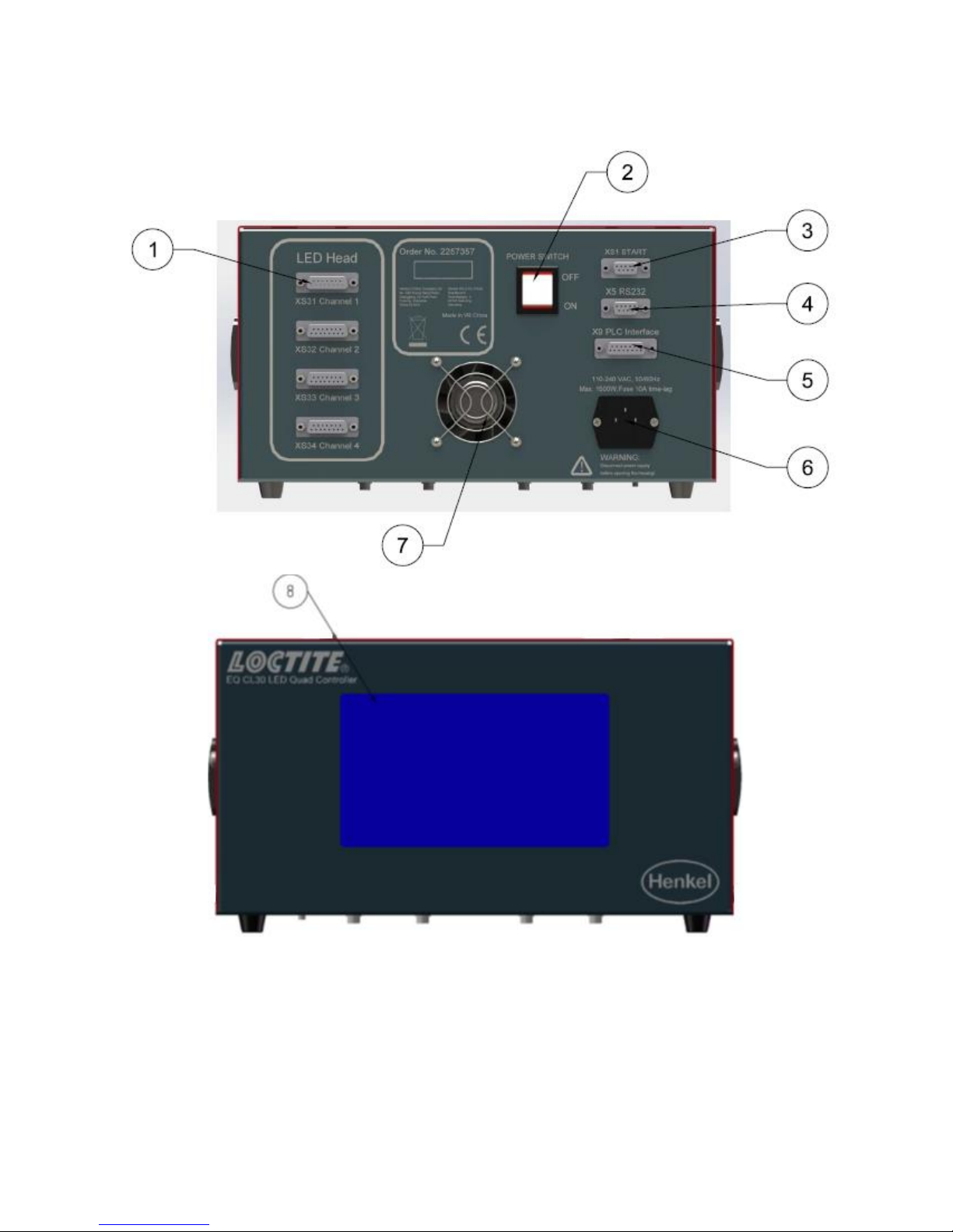
2.2 Display, operating elements and connections
1. Socket XS3: LED Head
2. Power Switch ON/OFF
3. Socket XS1: Start (The footswitch is connected here).
 Loading...