

Loctite CL15 UV Operation Manual
EQUIPMENT
CL15 UV Wand System
Item No. 1661548
Operation Manual
_
+
Enter
Warning: UV Energy is transmitted from the end of the
light guide. Protective eyewear equipped with side shields
are required that meet ANSI Z80.3 & Z87.1 Certification.
Loctite® CL15 UV Curing Wand System
Part Number: 1661548

TABLE OF CONTENTS
1. PLEASE OBSERVE THE FOLLOWING
1.1 EMPHASIZED SECTION
1.2 ITEMS SUPPLIED
1.3 FOR YOUR SAFETY
1.4 FIELD OF APPLICATION, (INTENDED USA GE)
2. DESCRIPTION
2.1 THEORY OF OPERATION
2.2 OPERATING ELEMENTS AND CONNECTIONS
3. TECHNICAL DATA
4. INSTALLATION
4.1 SPACE REQUIREMENTS
4.2 CONNECTIONS
5. OPERATING THE UNIT
6. INSERTING AND REMOVING LIGHT GUIDES
6.1 INSTALLING SINGLE LIGHT GUIDE
6.2 BALANCING MULTI-POLE LIGHT GUIDES
7. CARE AND MAINTENANCE
7.1 REPLACING THE LAMP
8. TROUBLE SHOOTING
9. PIN CONNECTIONS
10. REPLACEMENT PARTS AND ACCESSORIES
11. WARRANTY

1. Please Observe the Following
1.1 Emphasized Sections
WARNING!
Refers to safety regulations and required measures that protect the operator or other
persons from injury or danger to life.
Caution!
Emphasizes what must be done or avoided so that the unit or other property is not
damaged.
Notice:
Gives recommendations for better handling of the unit during operation or adjustment,
as well as for service activities.
1.2 Items Supplied
Curing unit
High pressure mercury short arc bulb, (installed in curing unit)
Footswitch
UV safety glasses
Manual
Power Cord
1.3 For Your Safety
For safe and successful operation of the unit, read these instructions completely. If the
instructions are not observed, the manufacturer can assume no responsibility. Be sure
to retain this manual for future reference.
WARNING!
Always wear the included UV safety glasses or glasses that conform to ANSI
Z87.1/CSA Z94.3 when operating the unit.
WARNING!
Always cover hands, face and other parts of the body that may be exposed to UV light.
WARNING!
Never look into the end of the light guide.
WARNING!
Never open the shutter mechanism without the light guide installed.
WARNING!
Never remove the cover of the unit without first switching the power off and
unplugging the power cord.
WARNING!
Damage to the power cord or the housing can result in contact with live electrical parts.
Check the power cord and housing before each use. If the power cord or unit is
damaged, do not operate.

1. Please Observe the Following (continued)
Caution!
Never turn the unit on without the lamp connected to the power supply.
Caution!
The energy emitted from the end of the light guide can heat any surface that it is
directed at. Care must be taken to determine the proper offset distance and exposure
time.
Caution!
Turning the lamp on and off frequently will cause the UV output of the lamp to
decline at a faster rate. It is recommended that the unit be left on during breaks and
short down times.
Caution!
Avoid making sharp bends in the light guide, as this will cause a loss of UV energy or
possibly cause permanent damage. To prevent permanent damage, the minimum
bend radii are 2.4 inches for a single light guide and 1.6 inches for a dual light guide.
The unit may be repaired only by a Loctite® authorized service technician.
1.4 Field of Application, (Intended Usage)
This Loctite® UV CL15 Wand System is designed for use with Loctite products that
cure when exposed to ultraviolet light produced by the unit. The UV energy is
directed towards the product through a liquid filled light guide that is ordered
separately. Several configurations of light guides are available from Loctite®,
including single and dual ended types. The unit is also capable of interfacing with an
external relay or PLC circuit.
2. Description
2.1 Theory of Operation
When the unit is switched on, electrical power is imm
ignition should occur within several seconds. As soon as the lamp has completed the warm
up cycle, an internal relay will change state, making a closure across pins 3 and 4 of the
footswitch connector, (located on the rear panel of the unit). The front panel display will
indicate the progress at the warm-up period. Curing takes place when the shutter is opened,
allowing UV light to be directed from the end of the liquid filled light guide to the adhesive.
The curing parameters, (UV irradiance and exposure time) must be determined before use.
The UV irradiance, (the strength of the UV light), at the adhesive surface can be varied by
adjusting the distance of the light guide from the bond. If the light guide is moved to within
½ inch of the adhesive surface, vapors from the curing process may build up on the end of
the light guide, reducing the UV intensity over time. The UV exposure time required to
complete the curing process depends primarily on the UV irradiance and the properties of the
adhesive product.
ediately supplied to the lamp and

2. Description, (continued)
UV lamps undergo a gradual reduction in UV output over time and it is recommended that
the lamp output be monitored on a regular basis. Frequently turning the main power on and
off will increase the rate that the lamp degrades, therefore, it is recommended that the unit be
left on during short work breaks such as lunch and other idle periods.
The digital display is the user interface to the system. It is used to set and view the shutter
ON/OFF time, number of cycles, lamp hours, and system hours. During a cure cycle the time
and duration will be shown counting down for user viewing.
The timed exposure cycle starts by momentarily engaging the footswitch or when an
externally operated device such as a PLC makes a relay closure across pins 1 and 9 of the
nine pin foot switch connection, XS-1, on the rear panel. In the manual operating mode, the
shutter remains open for as long as the footswitch or alternate external device maintains
contact between pins 1 and 9.
Notice: The hour meter should only be reset when a new lamp is installed.
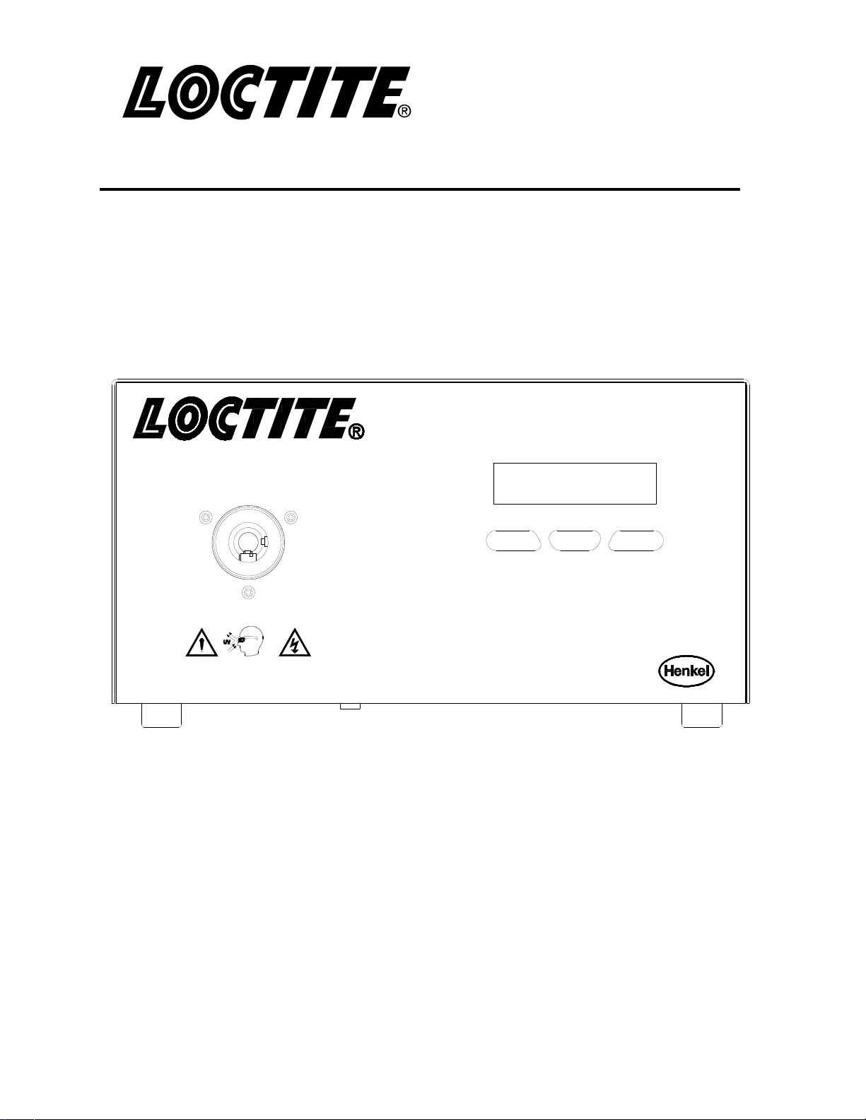
2.2 Operating Elements and Connections
The front panel is a membrane control pad with an LCD display. The keypad controls all
the major operating features.
Light Guide Receptacle Back Lit LCD Display
CL15 UV Wand System
Item No. 1661548
_
Down Button
Warning: UV Energ y is transmitted from the end of the
light guide. Protective eyewear equipped with side shields
are required that meet ANSI Z80.3 & Z87.1 Certification.
Up Button
Enter Button
+
Enter

2. Description (continued)
LCD Display
The digital display s
ON/OFF time, number of cycles, lamp hours, and system hours. During a cure cycle the
time and duration will be shown counting down for user viewing.
ENTER Button
The OK button allows the user to scroll through the levels of set-up param
used to accept any changes that are made to the current set of parameters.
UP Button (+)
The Up Button (+) allows the user to either select options on the left hand side of the screen
or increase values of set-up parameters.
Down Button (-)
The Down Button (-) allows the user to either select options on the right hand side of the
screen or decrease values of set-up parameters.
erves as the user interface. It is used to set and view the shutter
eters. It is also
2. Description (continued)
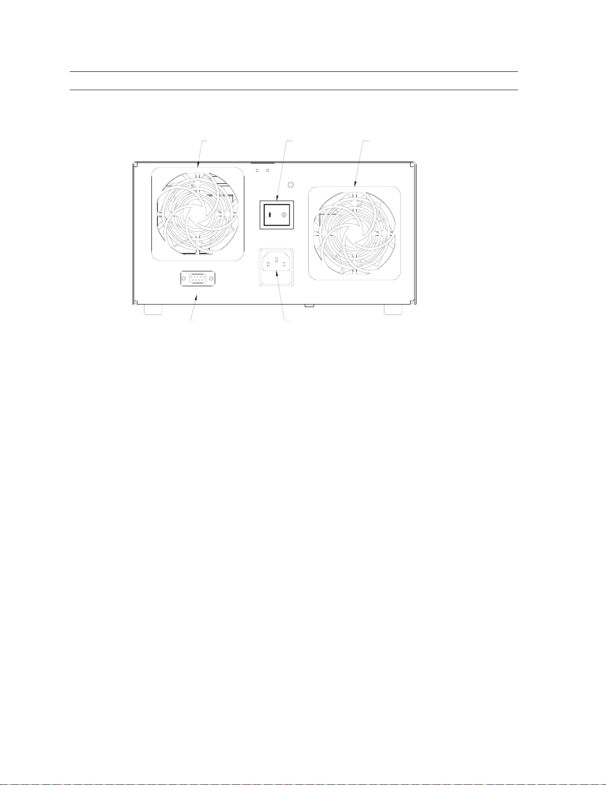
Back Panel
Intake Fan Exhaust Fan
90-240VAC
XS-1 T4AL250V CLEAN FILTER REGULARLY
Foot Switch
Connection
Main Power Switch
MADE IN USA
INPUT:
50/60Hz
Power Entry Module
Cooling Fans
The fan system is used to maintain the optimum temperature of the lamp while cooling the
optics and electronics. One fan is used for intake and the other fan is used for exhaust. The
intake fan has a removable filter that should be cleaned regularly, depending on the
environment.
Footswitch Connector (XS-1)
Nine pin D-sub with pins 1 and 9 being the start signal and pins 3 and 4 being the “lamp on”
signal, (relay contacts closed when lam
p is on).
 Loading...