

Loctite 980160 Operating Manual
®
EQUIPMENT
OPERATION MANUAL
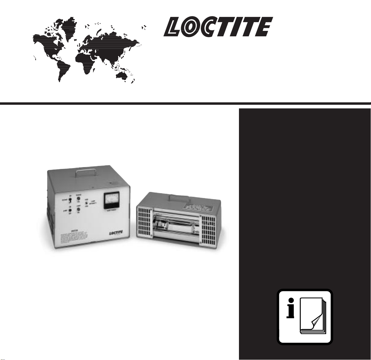
Loctite
High Intensity
Ultraviolet
Source
®
980160

Contents
Page No.
1 Please observe the following . . . . . . . . . . . . . . . . . . . . . . . . . . . . . . . . . . . . . . 1
1.1 Emphasized Sections . . . . . . . . . . . . . . . . . . . . . . . . . . . . . . . . . . . . . . . . . . . . . 1
1.2 Items Supplied . . . . . . . . . . . . . . . . . . . . . . . . . . . . . . . . . . . . . . . . . . . . . . . . . . 1
1.3 For Your Safety. . . . . . . . . . . . . . . . . . . . . . . . . . . . . . . . . . . . . . . . . . . . . . . . . . 1
1.3.1 Ultraviolet Light Safety. . . . . . . . . . . . . . . . . . . . . . . . . . . . . . . . . . . . . . . . . . . . . 1
1.3.2 Ozone Safety . . . . . . . . . . . . . . . . . . . . . . . . . . . . . . . . . . . . . . . . . . . . . . . . . . . 2
1.3.3 Thermal Safety . . . . . . . . . . . . . . . . . . . . . . . . . . . . . . . . . . . . . . . . . . . . . . . . . . 2
1.3.4 Electrical Safety . . . . . . . . . . . . . . . . . . . . . . . . . . . . . . . . . . . . . . . . . . . . . . . . . 2
2 Description . . . . . . . . . . . . . . . . . . . . . . . . . . . . . . . . . . . . . . . . . . . . . . . . . . . . 3
2.1 Field of Operation . . . . . . . . . . . . . . . . . . . . . . . . . . . . . . . . . . . . . . . . . . . . . . . . 3
2.2 Theory of Operation . . . . . . . . . . . . . . . . . . . . . . . . . . . . . . . . . . . . . . . . . . . . . . 3
2.3 Operating Elements and Controls . . . . . . . . . . . . . . . . . . . . . . . . . . . . . . . . . . . . 5
3 Installation. . . . . . . . . . . . . . . . . . . . . . . . . . . . . . . . . . . . . . . . . . . . . . . . . . . . . 5
3.1 Utility and Space Requirements . . . . . . . . . . . . . . . . . . . . . . . . . . . . . . . . . . . . . . 6
3.2 Initial Set Up . . . . . . . . . . . . . . . . . . . . . . . . . . . . . . . . . . . . . . . . . . . . . . . . . . . . 6
3.3 Additional Cooling . . . . . . . . . . . . . . . . . . . . . . . . . . . . . . . . . . . . . . . . . . . . . . . . 6
4 Operation. . . . . . . . . . . . . . . . . . . . . . . . . . . . . . . . . . . . . . . . . . . . . . . . . . . . . . 7
4.1 Start Up . . . . . . . . . . . . . . . . . . . . . . . . . . . . . . . . . . . . . . . . . . . . . . . . . . . . . . . 7
4.2 Shut Down . . . . . . . . . . . . . . . . . . . . . . . . . . . . . . . . . . . . . . . . . . . . . . . . . . . . . 7
4.3 Idle Time. . . . . . . . . . . . . . . . . . . . . . . . . . . . . . . . . . . . . . . . . . . . . . . . . . . . . . . 7
5 Care and Maintenance. . . . . . . . . . . . . . . . . . . . . . . . . . . . . . . . . . . . . . . . . . . . 8
5.1 Cleaning the Lamp and Reflector. . . . . . . . . . . . . . . . . . . . . . . . . . . . . . . . . . . . . 8
5.2 Removing the Lamp . . . . . . . . . . . . . . . . . . . . . . . . . . . . . . . . . . . . . . . . . . . . . . 8
5.3 Removing the Reflector. . . . . . . . . . . . . . . . . . . . . . . . . . . . . . . . . . . . . . . . . . . . 8
6 Troubleshooting . . . . . . . . . . . . . . . . . . . . . . . . . . . . . . . . . . . . . . . . . . . . . . . . 9
7 Recommended Spare Parts and Accessories . . . . . . . . . . . . . . . . . . . . . . . . 10
8 Warranty . . . . . . . . . . . . . . . . . . . . . . . . . . . . . . . . . . . . . . . . . . . . . . . . . . . . . 11
9 Appendix . . . . . . . . . . . . . . . . . . . . . . . . . . . . . . . . . . . . . . . . . . . . . . . . . . . . . 12
9.1 Figure 2 Lamp Unit . . . . . . . . . . . . . . . . . . . . . . . . . . . . . . . . . . . . . . . . . . . . . . 12
9.2 Figure 3 Electrical Schematic. . . . . . . . . . . . . . . . . . . . . . . . . . . . . . . . . . . . . . . 13

1 Please observe the following
1.1 Emphasized Sections
WARNING!
Refers to safety regulations and required safety measures that protect the operator or other
persons from injury or danger to life.
Caution!
Emphasizes what must be done or avoided so that the unit or other property is not damaged.
☞
Notice:
Gives recommendations for better handling of the unit during operation or adjustment as well as
for service activities.
1.2 Items Supplied
Carefully remove the system from its shipping carton and inspect it for any signs of damage. Any
damage should be reported immediately to the carrier. Refer to the list of supplied parts below
and compare to the contents. Report any missing parts promptly to the Loctite customer service
department at 1-800-LOCTITE or 1-800-562-8483.
(1) Power Supply with attached input power line cord and output cable with connector to
irradiator.
(1) UV Lamp and Irradiator (reflector) Assembly.
(1) Pair UV Safety Glasses.
(1) Instruction manual.
1.3 For Your Safety
IMPORTANT!
Do Not operate the unit before reading this section.
1.3.1 Ultraviolet Light Safety
The Loctite®High Intensity Ultraviolet Source is a source of long wavelength ultraviolet light
used to cure light sensitive products. It produces intense ultraviolet (UV) light, which can cause
serious burns to the skin and eyes. The light is similar to that which causes sunburn but is
much stronger. Like a sunburn, UV burns of the eyes or skin are not felt until several hours
after the burn occurs. All personnel involved in the operation of the High Intensity Ultraviolet
Source should be familiar with the safety guidelines described in this manual. The following
guidelines should be followed at all times to ensure protection from the ultraviolet light.
1. The High Intensity Ultraviolet Source has no shielding. The user must provide shielding to
prevent exposure of operating personnel to direct or first bounce reflected light. Refer to
Section 3 of this manual for additional information.
2. UV protective glasses with side shields should be worn when working with and around the
lamp system. Glasses should meet ANSI Z87.1 certification.
1
1 Please observe the following (continued)
3. Potentially exposed skin should be covered. Long sleeves and protective gloves should be
worn when placing and removing parts from under the lamp.
4. Never look directly at the output from the lamp or directly into the lamp/reflector.
5. Removing the glass filter from the lamp housing may speed up the cure of some products,
however, this will also speed injury to eyes and unprotected skin. DO NOT OPERATE THE
LAMP WITH THE FILTER REMOVED.
UV safety is the responsibility of the user, especially when operating the unit in a non-standard
configuration. When in doubt about UV safety, consult a Loctite technical specialist at
1-800-LOCTITE OR 1-800-562-8483.
1.3.2 Ozone Safety
3
A secondary hazard is the ozone (O
< 240 nanometers with atmospheric oxygen. Use this equipment with adequate ventilation.
The current (Feb. 1999) threshold limit value (TLV) for ozone is 0.1 ppm (parts per million).
There are several techniques for monitoring ozone concentrations. One of the simplest, is
equipment supplied by National Draeger, Inc., of Pittsburgh, PA. Their devices employ a direct
reading, disposable detection tube which is capable of measuring ozone concentrations of 0.05
ppm to 14 ppm.
Ozone concentrations can be minimized with good local ventilation. Ozone generation can be
prevented entirely by the use of an oxygen-excluding nitrogen atmosphere under the lamp or by
using an “ozone free” lamp. “Ozone free” lamps have a quartz sleeve or tube which blocks
wavelengths < 240 nanometers. See the Spare Parts List on page 10 of this manual for the part
number of the “ozone free” lamp.
). Ozone is generated by reaction of UV light of wavelength
1.3.3 Thermal Safety
A third safety concern with medium-pressure mercury light sources is heat. UV lamps generate
significant amounts of energy in the infrared region. Infrared radiation heats all nearby objects. In
addition, the quartz sleeve of the UV lamp must be maintained at between 600°C and 800°C to
vaporize the mercury in the lamp. The user must supply sufficient cooling and/or heat shielding
to keep the system at a safe temperature for the operators. The cooling must also keep the parts
being cured at a safe operating temperature.
1.3.4 Electrical Safety
1. Connect the unit to a three-wire (grounded) outlet with correct ampere capacity.
2. The power supply enclosure contains a high voltage transformer which supplies high lamp
starting voltages. This unit should be serviced only by qualified electricians or by a Loctite
Service Technician.
2

2 Description
2.1 Field of Application
The High Intensity Ultraviolet Source is a ultraviolet energy source designed for a wide range of
applications involving the curing of Loctite®ultraviolet activated adhesives and coatings. With the
proper ultraviolet light shielding, and cooling, and venting this light source can be used in both
prototype and production applications.
2.2 Theory of Operation
The Ultraviolet Source is designed for the curing of Loctite®UV activated adhesives and
coatings. It is ideal for adapting to customers' current production equipment; the lamp unit can
be mounted to existing conveyors and indexing equipment (UV shielding isrequired to protect
the operator). Aseparately packaged power supply is powered by 120 VAC, 20 Amp, 60 Hz
electrical power and can be located up to 5 feet from the lamp. Power can be monitored with the
built-in watt meter. A high/low intensity switch (300 w/inch to 200 w/inch) located on the front
panel of the power supply unit allows the lamp to idle at low power when not in use.
The lamp unit should be located approximately 5 inches above the curing plane. When placed at
this height, the curing area will be approximately 4.5 inches x 6 inches for a single UV Source.
Multiple sources can be used for larger curing area.
3
 Loading...