

Loctite 97211 Operating Manual

1
Operating Manual
Bedienungsanleitung
Online Preamplifier
Online-Vorverstärker
97211
2
R
97123
R
97123
ESC
97211
Loctite Deutschland GmbH
Made in Germany
cat. no. 97211
R
97211
Output
1V
5V
10V
97152
1-2x
1x
97153
1
ESC
Num
0
9
6
-
8
Start
3
P
4
5
2
7
A
B
C
D
97153
+
1-4x
1x
97113/97295
97114/97295
97138
97140
97152
ESC
Start
A
B
97204
97204

3
Content
English.....................................................................................................................................4-31
Deutsch..................................................................................................................................32-57

4
Content
1 Please observe the following .................................................................................6
1.1 Emphasized Sections ....................................................................................................... 6
1.2 Items Supplied .................................................................................................................7
1.3 For Your Safety................................................................................................................7
1.4 Field of Application (Intended Usage) ............................................................................ 7
2 Description.............................................................................................................8
2.1 Theory of Operation......................................................................................................... 8
2.2 Displays, Operating Elements and Connections............................................................ 11
3 Technical Data.....................................................................................................12
4
Installation ...........................................................................................................13
4.1 Enviromental and Operating Conditions ....................................................................... 13
4.2 Space Requirements.......................................................................................................13
4.3 Connecting the Unit....................................................................................................... 14
4.3.1 Automatic Controller 97123 .......................................................................................... 14
4.3.2 Dual Channel Automatic Controller 97152................................................................... 14
4.3.3 Multi Channel Automatic Controller 97153.................................................................. 15
4.3.4 Pressure Sensor.............................................................................................................. 16
4.4 Disconnect the Pressure Sensor ..................................................................................... 17

5
Content
5 Measuring.............................................................................................................18
5.1 Adjusting of the Dispense Quantity................................................................................18
5.2 Adjusting the Preamplifier 97211...................................................................................19
5.3 Setup and Storing a Reference at the Controller ............................................................20
5.4 Monitoring......................................................................................................................21
5.5 Software Interface for Statistic Process Control (SPC)..................................................23
6 Care, Cleaning and Maintenance .........................................................................24
7
Troubleshooting ...................................................................................................24
8
Annex...................................................................................................................25
8.1 Spare Parts......................................................................................................................25
8.2 Pin Assignment...............................................................................................................26
8.2.1 4 pin Plug for Connection to Controller.........................................................................26
8.2.2 4 pin Socket for Connection to the Pressure Sensor.......................................................26
8.2.3 PLC Interfaces XS 5 Controller 97123 and
XS 10Controller 97152 (internal voltage)......................................................................27
8.2.4 PLC Interfaces XS 5 Controller 97123 and
XS 10 Controller 97152 (external voltage) ....................................................................28
8.2.5 SPS-Interface to Controller 97153 .................................................................................28
8.3 Declaration of Conformity..............................................................................................29
6
1 Please observe the following
For safe and successful operation of the unit, read these instructions completely.
If the instructions are not observed, the manufacturer can assume no responsibility.
Be sure to retain this manual for future reference.
Refer to the technical data sheet for the LOCTI TE
®
product used at www.loctite.com or contact
your local technical department.
1.1 Emphasized Sections
WARNING!
Warning is the signal word used to indicate a potentially hazardous situation which, if not
avoided, could result in death or severe injury.
CAUTION!
Caution is the signal word used to indicate a potentially hazardous situation which, if not
avoided, could result in moderate or minor injury.
☞
Note!
Gives recommendations for better handling of the unit during operation or adjustment as well as
for service activitie s.
The numbers printed in bold in the text refer to the corresponding position numbers in the
illustration on page 11.
• The point emphasizes an instruction step.
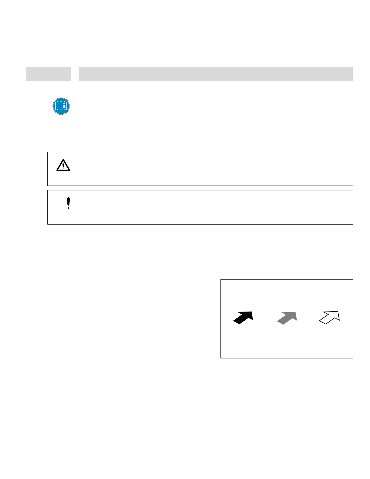
Instruction steps in the illustrations are
indicated with arrows.
When several instruction steps are indicated
in an illustration, the shading of the arrow has
the following meaning:
Black arrow = 1
st
step
Grey arrow = 2
nd
step
White arrow = 3
rd
step
7
1 Please observe the following
1.2 Items Supplied
1 Preamplifier 97211, Order Code No. 215992 1 Connection Cord Preamplifier to
1 Operating Manual 97211 Controller
Purchasing the Preamplifier 97211 includes the permission to use the monitor software of the
controller 97123, 97152 and 97153
☞
Note!
As a result of technical development, the illustrations and descriptions in this instruction manual
can deviate in detail from the actual unit delivered.
1.3 For Your Safety
WARNING!
Only an authorized Henkel service representative may repair the unit.
Observe manufacturer’s instructions!
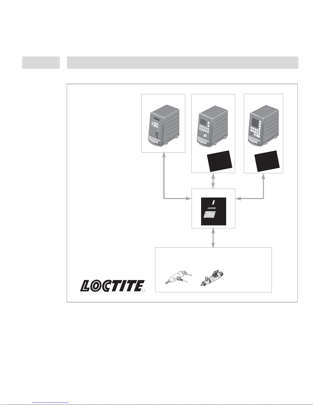
1.4 Field of Application (Intended Usage)
The integrated flow monitor of a Loctite controller in connection with the Preamplifier Online
Monitor 97211 is used for monitoring the quality and quantity of adhesive dispensed on parts, i.e.
the flow monitor recognizes and evaluates dispensing defects with respect to quality and quantity.
Such defects include:
– Air bubbles in the dispensing system
– Pressure changes in the dispensing system
– Lost or clogged dispensing nozzle
– Touch down of dispensing nozzle onto substrate.
It has been designed specifically for applications requiring high accuracy in dispensing Loctite
adhesives. It is an ideal tool for quality assurance. The flow monitor is used mainly in the
following types of workstations:
– Manual work stations handling precision manufacturing jobs or safety relevant parts.
– Assembly lines with robot stations.
– Assembly lines with automatic in-feed and out-feed.
– CNC workstations.
Necessary LOCTITE
®
controllers:
– Automatic Controller 97123 or
– Automatic Controller 97152 or
– Multi Channel Automatic Controller 97153
In order to integrate such a monitoring system in the production process a special dispensing
valve with an integrated pressure sensor is required.
8
2 Description
2.1 Theory of Operation
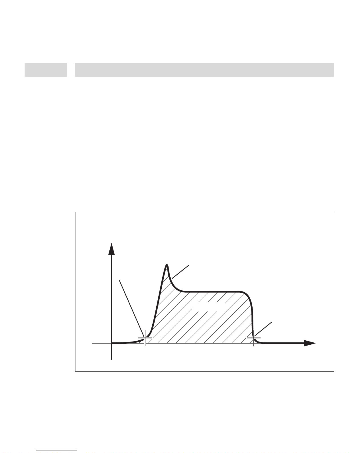
The integrated flow monitor of the Loctite® controller in connection with the Preamplifier 97211
measures the dispense pressure characteristic by means of a pressure sensor and stores this
parameter. The pressure sensor is integrated in the dispensing valve. The measuring time
corresponds with the dispense time sequence. The controller compares the measured pressure
characteristic with a previously stored reference characteristic, based on four different criteria:
– Dispensing time
– Integral of pressure characteristic; corresponds with quantity of product dispensed
– Length of envelope curve for pressure characteristic
– Center of gravity
If the measured values are within the pre-set tolerance zone in comparison to the reference value,
this dispensing cycle is recognized as o. k. and the ready signal will be available. If the deviation
is outside the tolerance zone, this dispensing cycle is detected as an error, and a fault is signaled.
This message is indicated on the display at the controller. It is also provided as a signal at the
PLC interface of the LOCTITE
®
controllers.
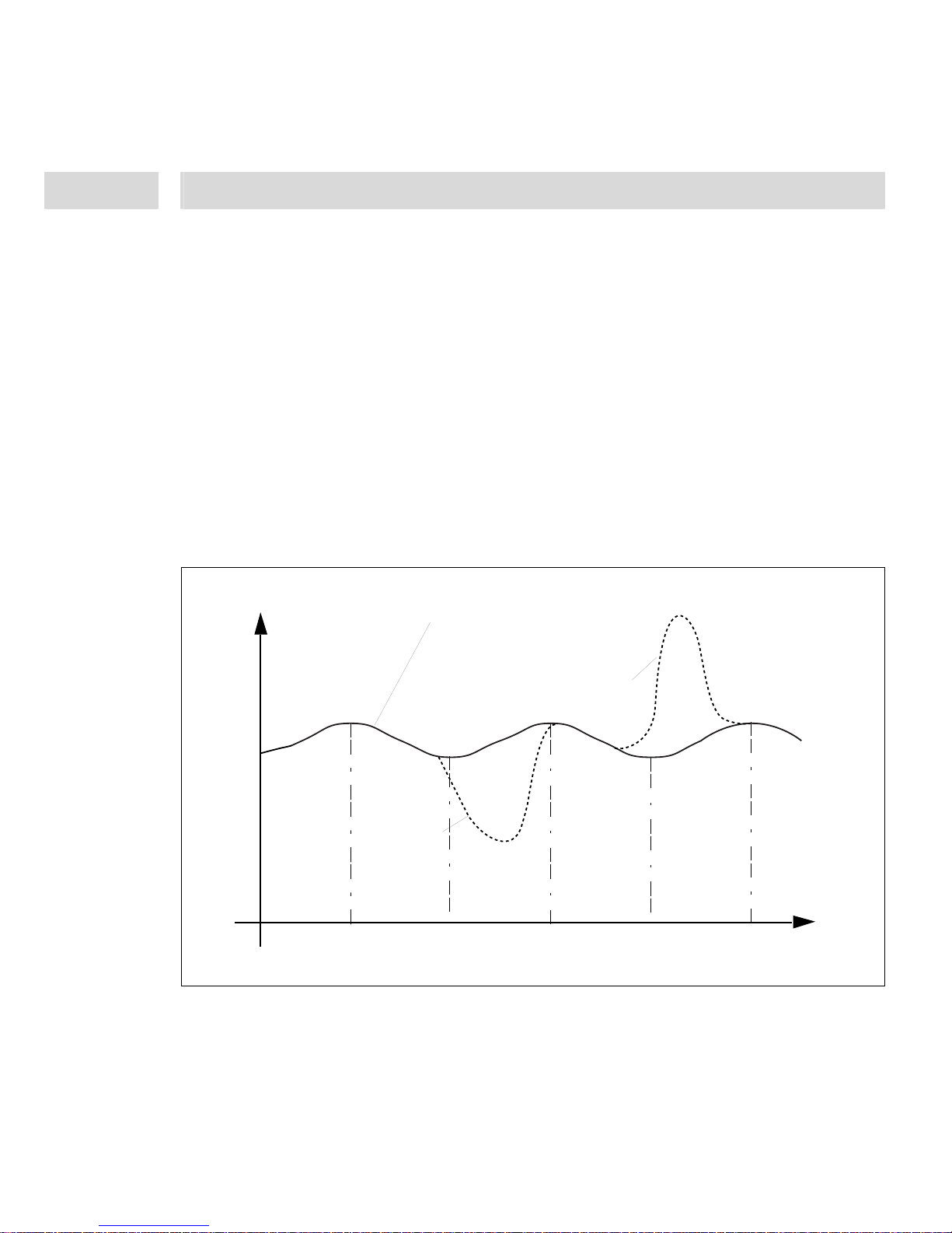
Integral (I)
P
Gesamtdosierzeit (T)
Total Dispensing Time
t
Hüllkurve (H)
Envelope Curve1. Offset
1
st
Offset
2. Offset
2
nd
Offset
Normaler Druckverlauf mit einem Dosierventil
Typical Pressure Characteristic with a Dispensing Valve
9
2 Description
It measures the last preceding dispensing cycle relative to a reference measurement previously
recorded and found to be o. k. The main adjustments have to be done in the setup menu of the
controller, to make sure that authorized personnel can store this reference value only. Depending
of the used controller the tolerance can be adjusted in 3 preadjusted ranges (low = 15%, middle =
35% or high = 55%) or from 1 to 99% to define the optimum between frequent false alarms and
reliable fault detection, see operating manual of the used controller. This value affects the
tolerance of the monitored parameters of integral and length of envelope curve.
Referred to the length of the envelope curve the tolerance value actually indicates accuracy in %.
An air bubble, a clogged needle or a needle touchdown each has a very strong effect on the
envelope curve length of the pressure characteristic. Therefore this is generally the governing
parameter for dispense monitoring.
If the controller 97152 or 97153 is used several different dispense quantities can be monitored.
The order of storing is fixed, but the reference can be selected per user’s own choice. The
advantage is, that different quantities on various work pieces can be preselected according to the
user’s requirement via the seri al inte rfac e.
P
t
Luftblase
Air bubble
Aufsetzer
Needle touch-down
Normaler Druckverlauf mit Schneckenpumpe
Normal Pressure characteristic with Rotor Pump
250 ms
500 ms
750 ms
1000 ms
1250 ms

10
2 Description
At the Preamplifier Online Monitor 97211 the amplification factor has to be adjusted to get an
optimum signal for correct interpretation at the Loctite controller.
Before each new start of a dispensing cycle, the controller generates a ready signal or error
signal. This happens at the end of each dispensing cycle. In case of failure of the sensor, no
measuring signal corresponding to the reference measurement can be generated. For this reason,
whenever a failure occurs, the system will always generate a fault signal at the end of the
dispensing cycle. Therefore the complete system is fail-safe if linked to a Loctite controller, i.e.
even in case of partial or complete failure no dispensing cycle will pass unchecked.
The type sensors used in the system are absolute pressure sensors. Variations in atmospheric
pressure such as they may result from weather conditions will affect measurements in a slight but
negligible degree. Temperature fluctuations have an effect on viscosity and consequently on
product dispensing where pressure reservoir/valve systems are used.
The integrated flow monitor of the Loctite controller recognizes the consequences of these
influencing factors, such as changes in the quantity of material dispensed.
To achieve absolutely constant dispensing results would actually require adapting the dispense
pressure to the temperature and thus to the viscosity. In the field, these variations in quantity due
to temperature fluctuations can mostly be tolerated.
However, if the dispensing result deviates too much from the desired bead configuration due to
major temperature variations, the displayed error rate will increase, and the dispensing pressure
will have to be adapted by authorized personnel. In this case a new reference measurement has to
be made.
Therefore, a seasonal check and, if required, adaptation of settings may be advisable.
Monitoring specifications:
– The sample rate is 1 kHz, (1000 measuring points per second).
– The minimum and maximum time of measurement are 0,03 and 15 seconds.
11
2 Description
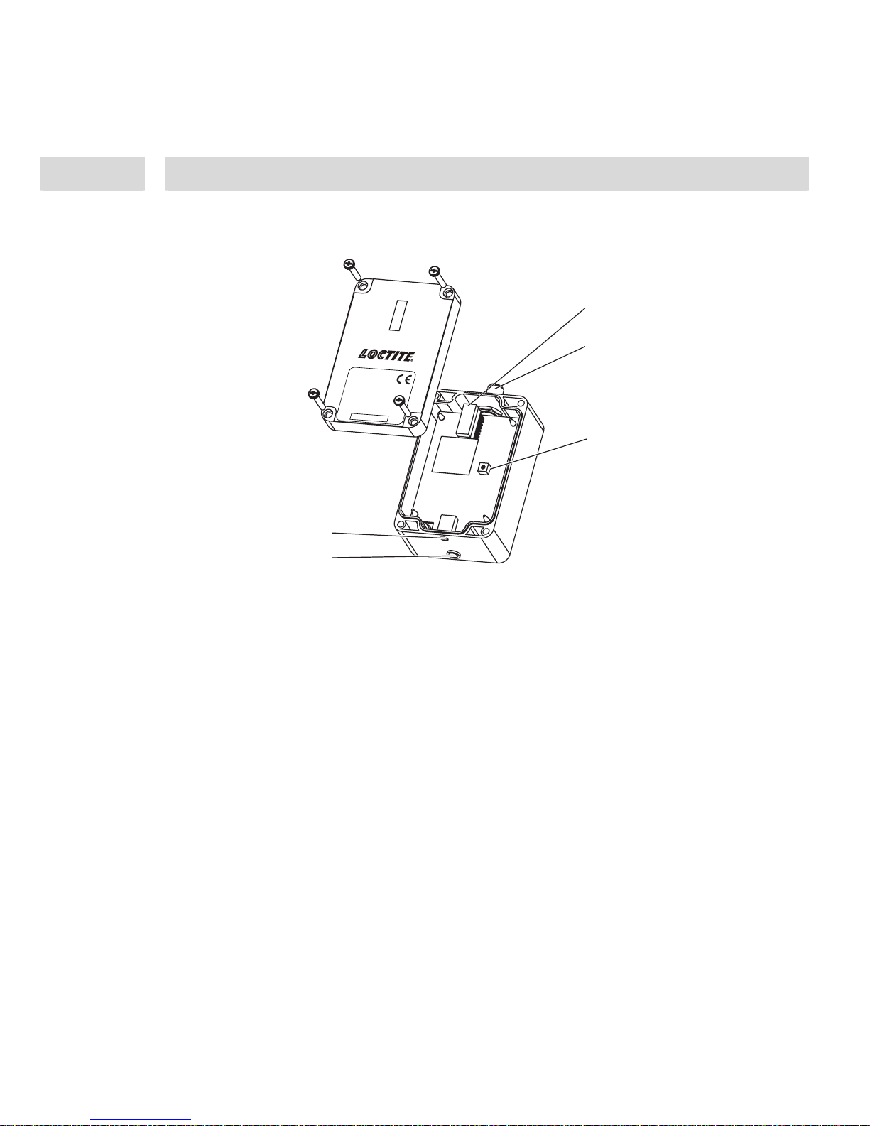
2.2 Displays, Operating Elements and Connections
1
LED Row 1-10 V OUTPUT
displays the measured and amplified signal from the sensor while measuring. The best adjustment
can be done by means of flushing the dispensing valve.
LED display:
– no dispensing: 0-2 LED lights,
– during flushing: 2 LED or more should light up additionally, but a few LED should not light.
This means that all LED must not light.
– during dispensing (or flushing) with clogged dispensing needle: it should light up at least 2
LED more, maximum all.
2
4 pin Plug for connection to controller
The supplied connection cord is connected here (Pin assignments see Section 8.2).
3
Potentiometer R10 to adjust the amplification factor
It is necessary to adjust the amplification factor for getting an optimum signal for the
interpretation at the Loctite controller.
4
Service Socket, for Loctite service only
5
4 pin Socket for connecting the pressure sensor
The cable of the pressure sensor is connected here (Pin assignments see Section 8.2).
1
2
3
4
5
Output
97211
10 V
5 V
1 V
Henke
l AG
& Co. KGaA
Standort M
ünchen
Gutenbergs
tr. 3
D-85748 Ga
rching b. M
ün
Order Code No. 215992
Made in Germany
Place for Serialnumbersticker

12
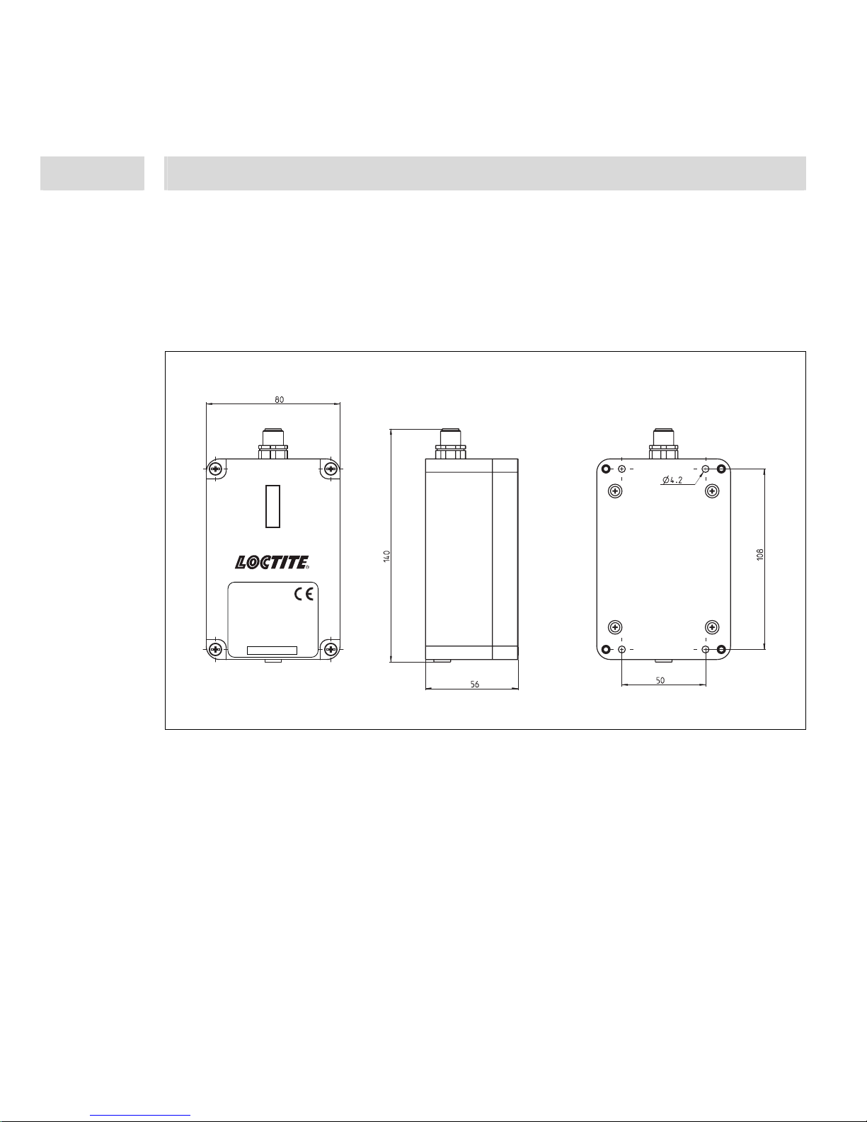
3 Technical Data
Power input 24 VDC
Signal output 1 – 10 VDC
Protection grade IP 65
Dimensions W x H x D: 80 mm x 57 mm x 141 mm:
Operating temperature +10 °C to +40 °C (+50 °F to +104 °F)
Storage temperature -10 °C to +60 °C (+14 °F to +140 °F)
Weight 0,24 kg
Max Length of the cable between Pressure
Sensor and Preamplifier
5 m
Max Length of the cable between Preamplifier
and Controller
10 m
13
4 Installation
4.1 Environmental and Operating Conditions
– Non-condensing humidity.
– No splash water.
– Housing may not get in touch with solvent!
4.2 Space Requirements
Output
97211
10 V
5 V
1 V
Henkel AG & Co. KGaA
Standort München
Gutenbergstr. 3
D-85748 Garching b. München
Order Code No. 215992
Made in Germany
Place for Serialnumbersticker
14
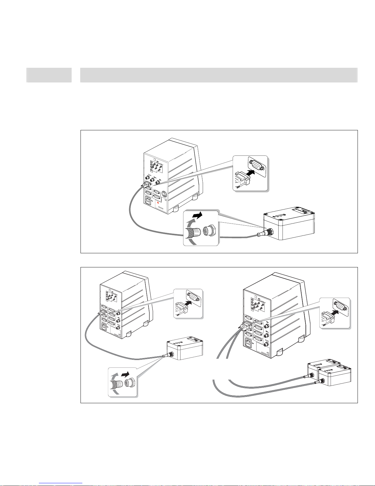
4 Installation
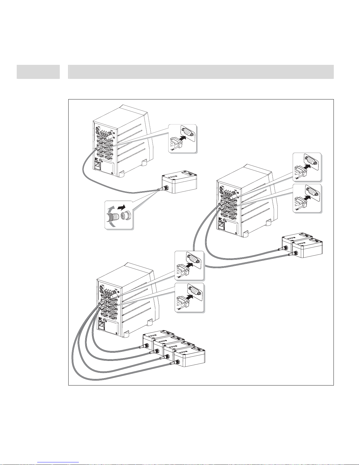
4.3 Connecting the Unit
• Use only the cable supplied
4.3.1 Automatic Controller 97123
4.3.2 Automatic Controller 97152
90-260 VAC
47-63 Hz
Phase = 1
XS1 Start
XS2 Reservoir
XS3 Flow Monitor
XS5 PLC Interface
XS4 RS232
2 AM
cat. no. 97123
Loctite (Ireland) Ltd.
Tallaght Business Park
Whitestown
Tallaght, Dublin 24, Ireland
Made in Germany
Power consumption max. 60 W
A
B
P in 6-8 bar
XS6
XS7
XS8
0
1
XS3 Flow Monitor
9
0
-2
6
0
V
A
C
47-63 H
z
P
h
a
se
=
1
XS1 S
tart
XS2 R
ese
rvoir
XS3 Flow Monitor
XS5 PLC Interface
XS4 R
S232
2
A
M
Type No. 97152
Henkel KGaA
Standort München
Gutenbergstr. 3
D-85748 Garching b. München
Made in Germany
Power consum
ption ma
x. 60 W
A
B
P in 6-8
bar
0
1
X
S
1
0
X
S
1
1
X
S
9
XS5 PLC Interface
XS5 PLC Interface
XS5 PLC Interface
P out
Order No. XXXXX
XS3
Flow Monitor
XS 3
A
B
90-260 VAC
47-63 Hz
Phase = 1
XS1 Start
XS2 Reservoir
XS3 Flow Monito
r
XS5 PLC
Interface
XS4 RS232
2 AM
Type No. 97152
Henkel KGaA
Standort M
ünchen
Gutenbergstr. 3
D-85748 Garching b.
München
Made in Germany
Power consumption max. 60 W
A
B
P in 6-8 bar
0
1
XS10
XS11
XS9
XS5 PLC
Interface
XS5 PLC
Interface
XS5 PLC
Interface
P out
Order No.
XXXXX
XS3 Flow Mo
nitor
XS 3
2 x 97211 with
1 x Splitter Cable 97529
15
4 Installation
4.3.3 Multi Channel Automatic Controller 97153
XS3 Flow Mo
nitor
XS4 Flow Mo
nitor
A
B
XS 3
XS 4
A
B
C
D
XS3 F
low Mo
nitor
XS4 F
low Mo
nitor
XS 3
XS 4
XS3
Flow Monitor
XS 3
4 x 97211 with
2 x Splitter Cable 97529
16
4 Installation
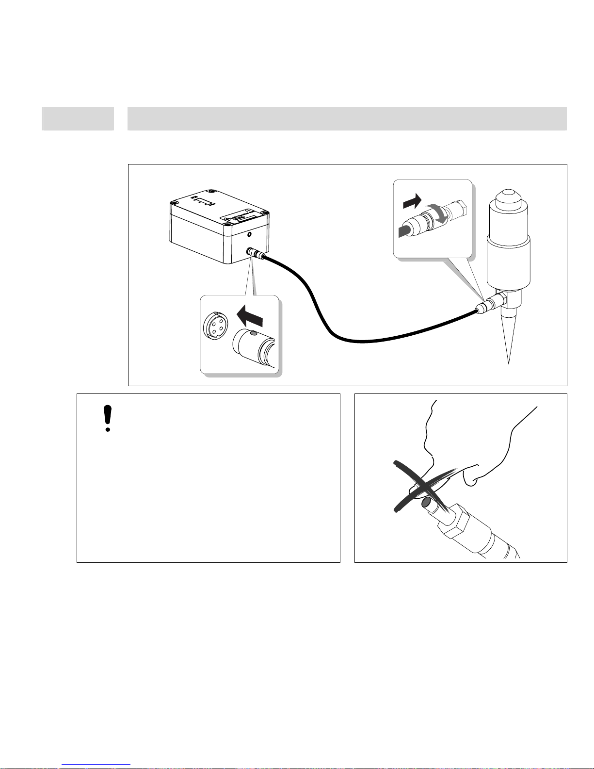
4.3.4 Pressure Sensor
Caution!
Handle sensor with absolute care!
No scratching or touching of the
membrane!
Never exceed a pointed pressure load in
the extremely thin and sensitive sensor
diaphragm.
Otherwise the sensor will be destroyed!
Apply the tightening torque:
min. 0.4 Nm, max. 0.6 Nm
17
4 Installation
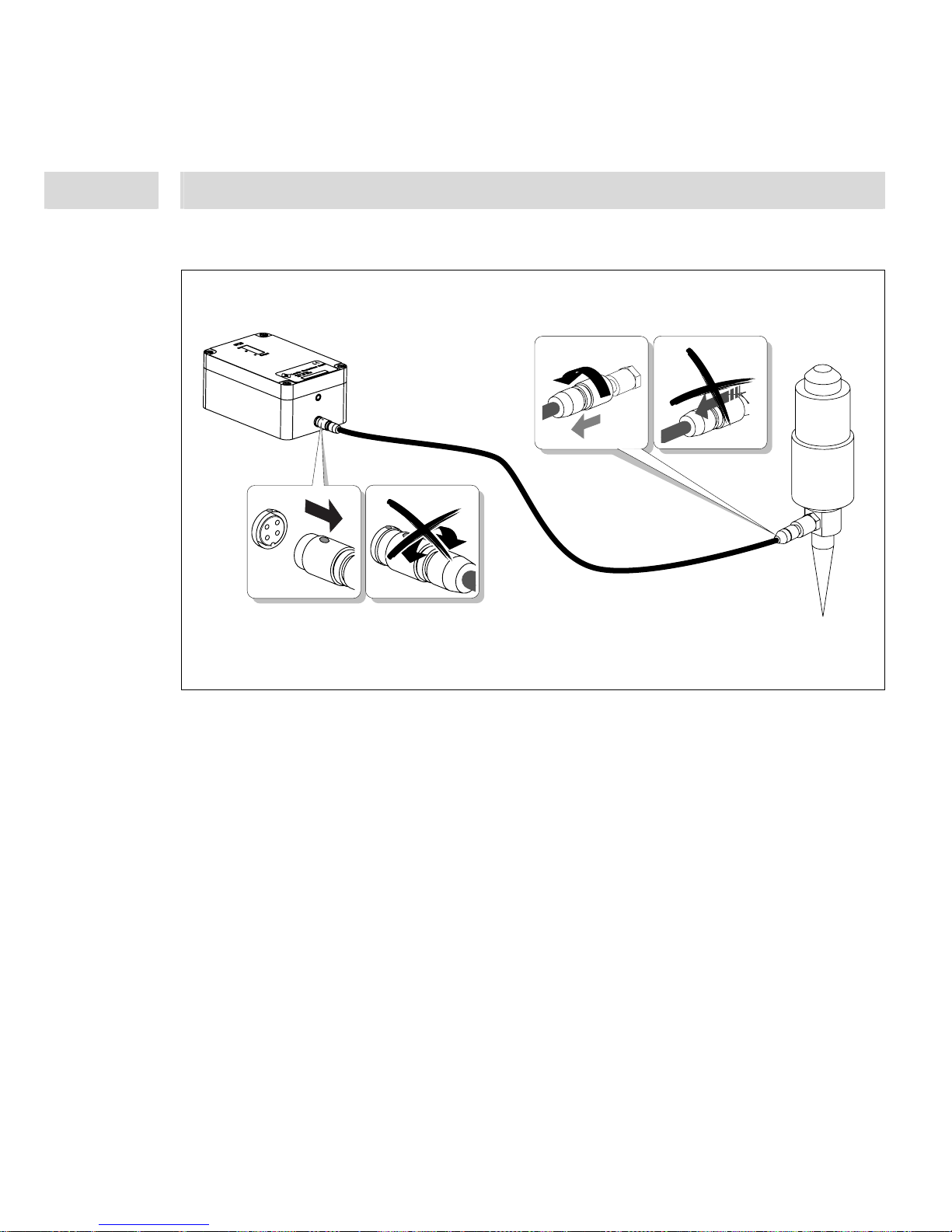
4.4 Disconnect the Pressure Sensor
 Loading...