

Loctite 97135, 97136 Operation Manual
EQUIPMENT
Operation Manual
Loctite
®
Diaphragm Valve
Part Numbers 97135/97136

Contents
Page No.
1 Please Observe the Following . . . . . . . . . . . . . . . . . . . . . . . . . . . . . . . . . . . . . . . . . 1-2
1.1 Emphasized Sections . . . . . . . . . . . . . . . . . . . . . . . . . . . . . . . . . . . . . . . . . . . . . . . . . . . 1
1.2 Items Supplied . . . . . . . . . . . . . . . . . . . . . . . . . . . . . . . . . . . . . . . . . . . . . . . . . . . . . . . . 1
1.3 For Your Safety. . . . . . . . . . . . . . . . . . . . . . . . . . . . . . . . . . . . . . . . . . . . . . . . . . . . . . . . 2
1.4 Field of Application (Intended Usage) . . . . . . . . . . . . . . . . . . . . . . . . . . . . . . . . . . . . . . 2
2 Description . . . . . . . . . . . . . . . . . . . . . . . . . . . . . . . . . . . . . . . . . . . . . . . . . . . . . . . . . . 3
2.1 Theory of Operation . . . . . . . . . . . . . . . . . . . . . . . . . . . . . . . . . . . . . . . . . . . . . . . . . . . . 3
2.2 Operating Elements and Connections . . . . . . . . . . . . . . . . . . . . . . . . . . . . . . . . . . . . . . 3
3 Technical Data. . . . . . . . . . . . . . . . . . . . . . . . . . . . . . . . . . . . . . . . . . . . . . . . . . . . . . . . 4
4 Installation . . . . . . . . . . . . . . . . . . . . . . . . . . . . . . . . . . . . . . . . . . . . . . . . . . . . . . . . . 5-6
4.1 Connecting to the Product Reservoir . . . . . . . . . . . . . . . . . . . . . . . . . . . . . . . . . . . . . . . 5
4.2 Connecting to the Controller. . . . . . . . . . . . . . . . . . . . . . . . . . . . . . . . . . . . . . . . . . . . . . 6
5 Dispensing . . . . . . . . . . . . . . . . . . . . . . . . . . . . . . . . . . . . . . . . . . . . . . . . . . . . . . . . . . 7
5.1 Priming the Diaphragm Valve. . . . . . . . . . . . . . . . . . . . . . . . . . . . . . . . . . . . . . . . . . . . . 7
5.2 Adjusting the Dispensed Quantity . . . . . . . . . . . . . . . . . . . . . . . . . . . . . . . . . . . . . . . . . 7
5.3 Shutdown . . . . . . . . . . . . . . . . . . . . . . . . . . . . . . . . . . . . . . . . . . . . . . . . . . . . . . . . . . . . 7
5.4 Returning to Operation . . . . . . . . . . . . . . . . . . . . . . . . . . . . . . . . . . . . . . . . . . . . . . . . . . 7
5.5 Upgrading the Feed Line/Fitting . . . . . . . . . . . . . . . . . . . . . . . . . . . . . . . . . . . . . . . . . . . 7
6 Care, Cleaning, and Maintenance . . . . . . . . . . . . . . . . . . . . . . . . . . . . . . . . . . . . . 8-10
6.1 Cleaning . . . . . . . . . . . . . . . . . . . . . . . . . . . . . . . . . . . . . . . . . . . . . . . . . . . . . . . . . . . . . 8
6.2 Maintenance . . . . . . . . . . . . . . . . . . . . . . . . . . . . . . . . . . . . . . . . . . . . . . . . . . . . . . . . . . 8
6.2.1 Disassembly . . . . . . . . . . . . . . . . . . . . . . . . . . . . . . . . . . . . . . . . . . . . . . . . . . . . . . . . . . 9
6.2.2 Assembly . . . . . . . . . . . . . . . . . . . . . . . . . . . . . . . . . . . . . . . . . . . . . . . . . . . . . . . . . . . 10
7 Troubleshooting . . . . . . . . . . . . . . . . . . . . . . . . . . . . . . . . . . . . . . . . . . . . . . . . . . . . . 11
8 Annex . . . . . . . . . . . . . . . . . . . . . . . . . . . . . . . . . . . . . . . . . . . . . . . . . . . . . . . . . . . 12-13
8.1 Accessories and Spare Parts . . . . . . . . . . . . . . . . . . . . . . . . . . . . . . . . . . . . . . . . . . . . 12
8.2 Manufacturer’s Declaration. . . . . . . . . . . . . . . . . . . . . . . . . . . . . . . . . . . . . . . . . . . . . . 13
9 Warranty (Excluding Germany) . . . . . . . . . . . . . . . . . . . . . . . . . . . . . . . . . Back Cover

1. Please Observe the Following
1
1.1 Emphasized Sections
Warning!
Refers to safety regulations and required safety measures that protect the operator or other
persons from injury or danger to life.
Caution!
Emphasizes what must be done or avoided so that the unit or other property is not damaged.
Notice:
Gives recommendations for better handling of the unit during operation or adjustment as well as
for service activities.
The numbers printed in bold in the text refer to the corresponding position numbers in the
illustration on page 3.
• The point emphasizes an instruction step.
Instruction steps in the illustrations are indicated
with arrows.
When several instruction steps are indicated in
an illustration, the shading of the arrow has the
following meaning:
Black arrow = 1st step
Grey arrow = 2nd step
White arrow = 3rd step
1.2 Items supplied
(1) Diaphragm Valve 97135 or (1) Diaphragm Valve 97136
(1) Product Feed Line 1/4 inch
(1) Needle Variety Kit 97262
(1) Operating Manual
As a result of technical development, the illustrations and descriptions in this instruction manual
can deviate in detail from the actual unit delivered.
☞
☞
1. Please Observe the Following (continued)
1.3 For Your Safety
For safe and successful operation of the unit, read these instructions completely. If the instructions
are not observed, the manufacturer can assume no responsibility.
If chemical products are not properly handled, damage to health can result!
• Observe general safety regulations for the handling of chemicals!
• Observe manufacturer’s instructions!
• Request a safety data sheet for the Loctite
®
product used!
• When working with pressurized air, wear protective glasses!
1.4 Field of Application (Intended Usage)
The Diaphragm Valves 97135/97136 are suitable for the exact application of Loctite®products.
They show no suckback.
The Diaphragm Valve 97135 is equipped with an internal product bore of ø 2 mm. It is used for
anaerobic products up to a viscosity of 2,500 mPas.
The Diaphragm Valve 97136 is equipped with a internal product bore of ø 3 mm. It is used for
anaerobic thixotropic products up to a viscosity of 5,000 mPas.
For each product and corresponding application of the dispense valves, various dispensing needle
types and sizes are available:
- Conical dispensing needles, made of polyethylene, for viscous products and large
dispensed quantities.
- Stainless steel needles for thin fluids and UV curing products.
- Flexible dispensing needles of polyethylene.
For high flow rates, the diaphragm valve can be upgraded from feed line 1/4" to 3/8" by the feed
line upgrade kit 97220.
The diaphragm valve is used as a stationary applicator unit. It is mounted directly at the
dispensing position. The free end of the product feed line is connected to the product reservoir.
As product reservoirs, 0.5 liter and 2 liter tanks are available.
The control of the diaphragm valve is provided by a Loctite
®
control unit.
2
2. Description
2.1 Theory of Operation
The Loctite®product is transported through a product feed line to the diaphragm valve by the
dispensing pressure in the product reservoir. At the shut off valve assembly, PTFE material is used
for the area in contact with the adhesive to prevent curing of adhesive in this part of the
diaphragm valve. The opening of the diaphragm valve takes place by pressurizing an internal
single acting cylinder. In the inactive position, the diaphragm valve is closed by spring force.
Sealing in idle position is achieved by a piston pushing against a diaphragm which seals off the
product bore in the valve.
The floating mounted diaphragm enables easy repair and service. As a result the diaphragm valve
is not suitable for moisture sensitive product like cyanoacrylates.
The amount of product dispensed is controlled by:
- The amount of pressure in the reservoir.
- The length of time the shut off valve remains open.
- The dispensing needle.
The more precise and constant the amount of Loctite
®
product, the longer the dispensing time and
the lower the dispensing pressure.
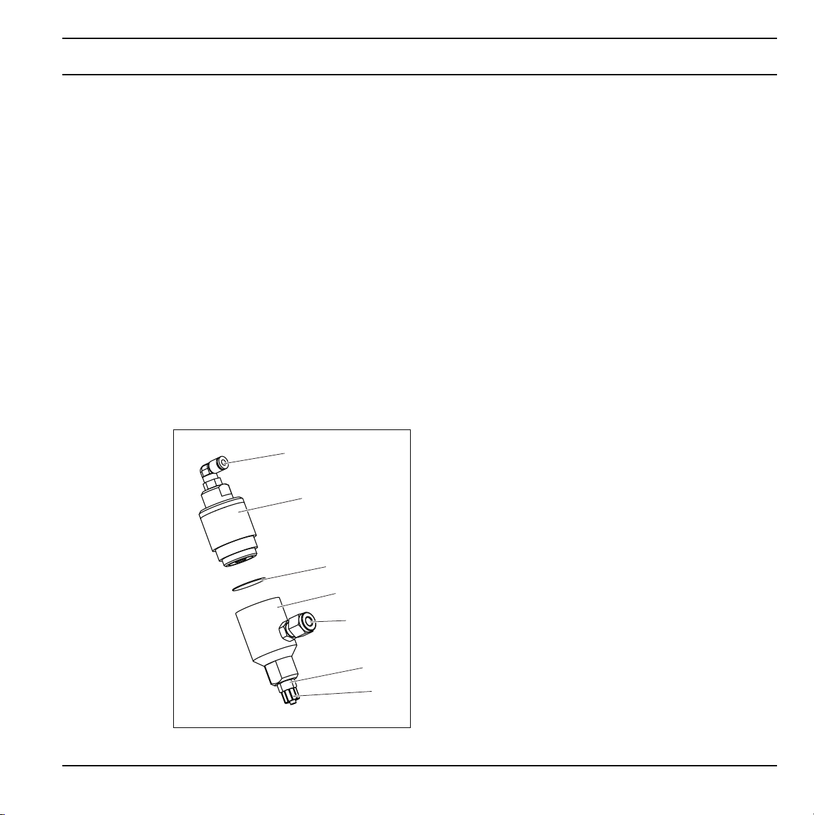
2.2 Operating Elements and Connections
1
2
3
4
5
6
7
1 Pressure hose connection
2 Actuator assembly
3 Diaphragm
4 Shut off valve assembly
5 Product feed line connection
6 Luer-Lok adapter
7 Luer-Lock
3
 Loading...