

Loctite 97111, 97112, 97116 Operation Manual
WORLDWIDE
EQUIPMENT
OPERATION MANUAL
Hand-held
Applicator
97111
97112
97116
GLOBAL AVAILABILITY
GLOBAL SERVICE

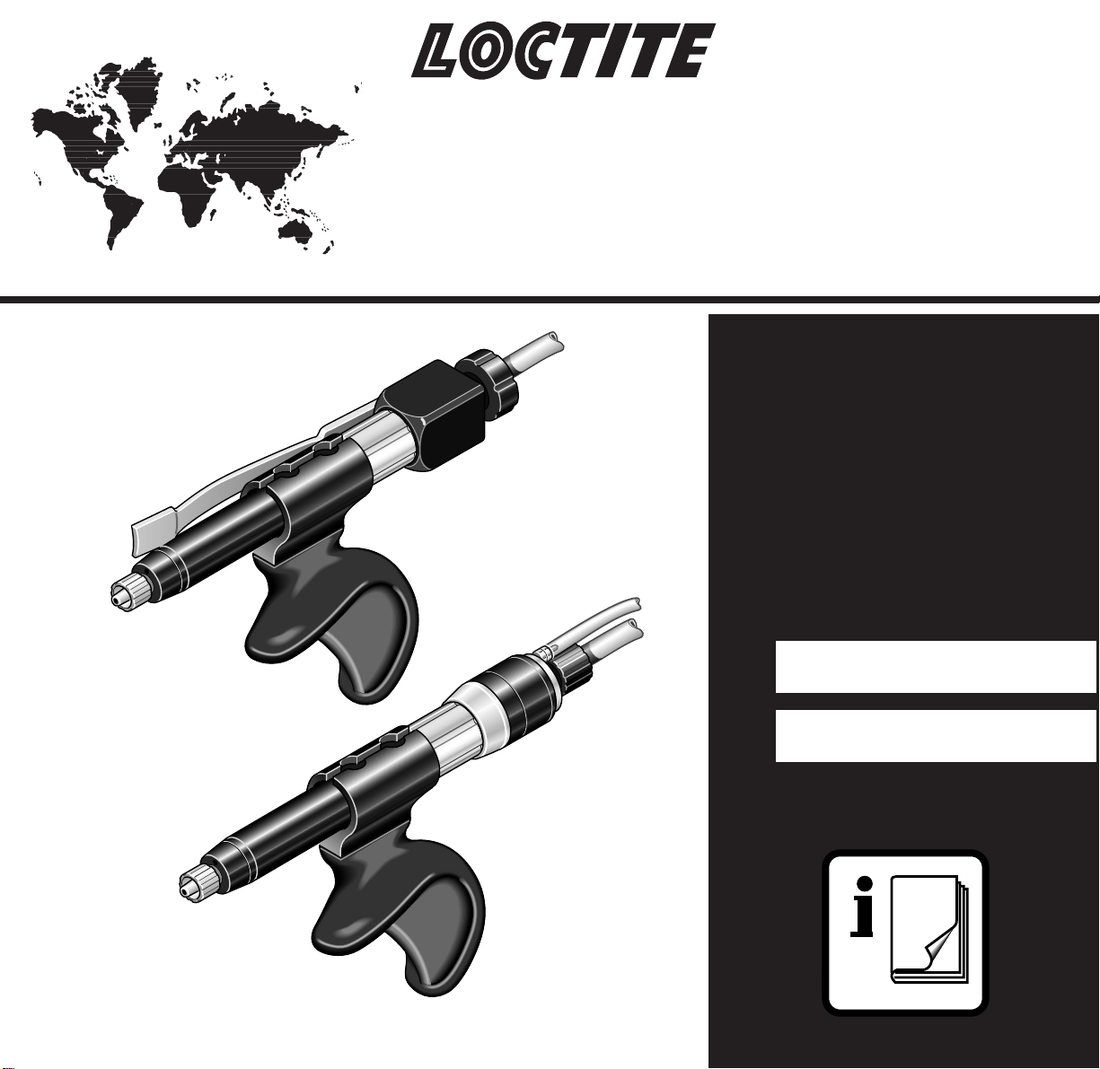
HAND-HELD APPLICATOR
97111/97112/97116
AN INTEGRATION OF ADHESIVE AND EQUIPMENT TECHNOLOGY
FEATURES
• Ergonomically designed for hand comfort and application control
• Low actuation force to reduce hand fatigue
• Designed with a suck-back feature for dispensing accuracy and control
• Adaptable to optional reservoirs based on product package
• Dispenses Loctite
innovative chemistries up to 50,000 cPs
• Worldwide Availability
• Worldwide Service
• Application support for integrating both the adhesive and equipment interface
For additional information on Loctite Worldwide Adhesives and
Equipment, please contact your local Loctite representative for a
copy of the Loctite Design Handbook.
1
2
3
4
4
6
11
10
6
97116
97111
97112
97116
5
6
6
8
9
7
5
R
97110
Change
Off
On
Power
Refill
Empty
RR
RR
97105
R
97110
Change
Off
On
Power
Refill
Empty
RR
RR
R
97102
CONT
bar
psi
R
0,5
1
1,5
1,6
5
10
15
20
23
psi
bar
10
20
40
60
80
100
120
140
psi
bar
2
4
6
8
97101
97113/14.Titel Raster
97113/14.Titel Raster
R
97103
ESC
A
B
A
B
B
A
R
R
START CONT
bar
psi
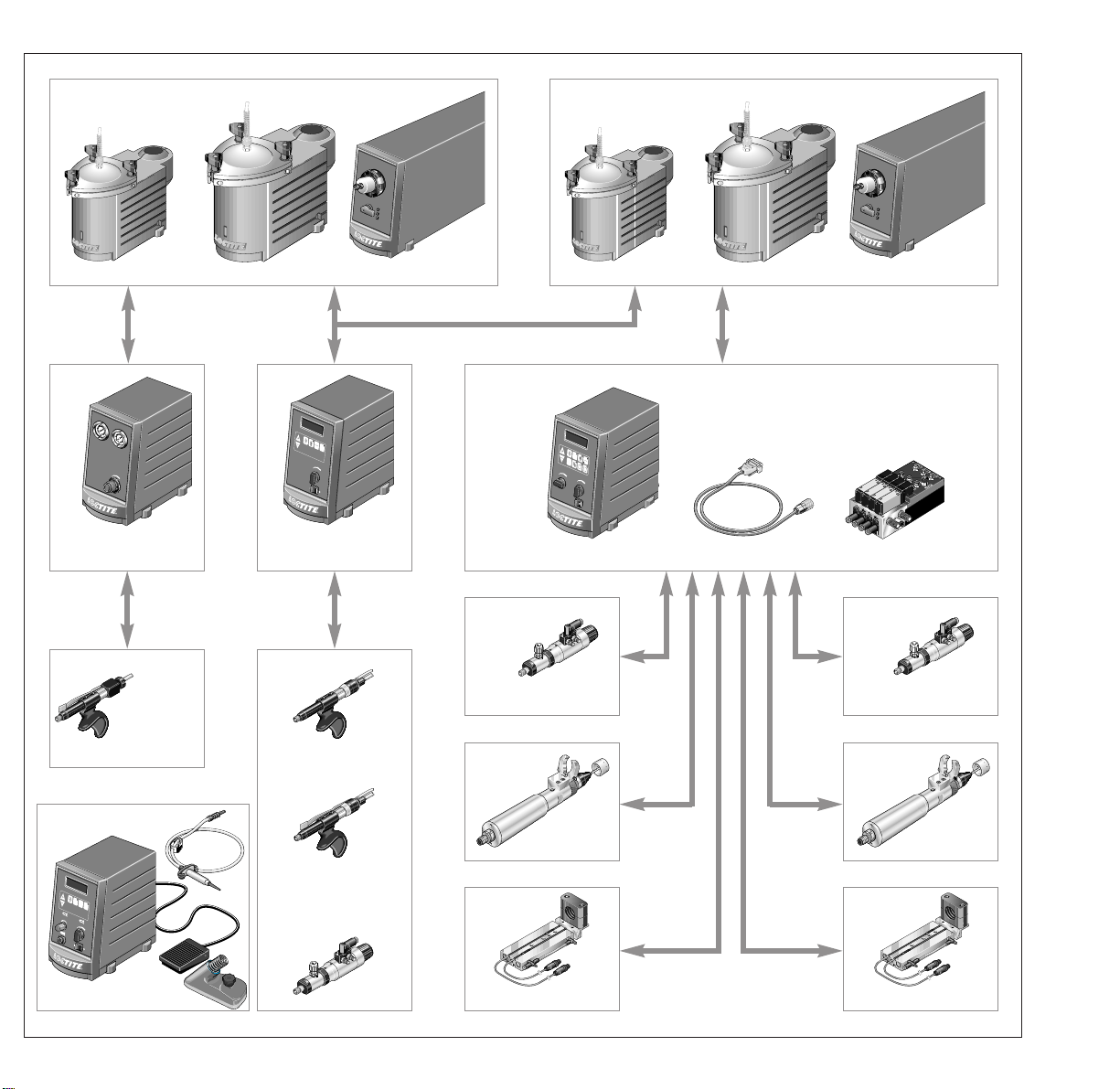
97006
97107
97109
97106
97108
97110
1x
97101
Manual Controller
97111
Hand-held
Applicator
Reservoir Options
97102
Semi-Automatic
Controller
97112
97116
1x
1x
97103 + 97204
97113
97114
Dispense Valve
97115
Reservoir Options
2x
Automatic Controller
97113
97114
Dispense Valve
97115
97006
Syringe System
97113
97114
Rotospray
97118
97119
Advancing Slide
Rotospray
97118
97119
Advancing Slide

Contents
Page No.
1 Please observe the following
1.1 Emphasized Sections 1
1.2 Items Supplied 1
1.3 For Your Safety 2
1.4 Usage 2
2 Description
2.1 Operating Elements and Connections 2, 3
2.2 Theory of Operations 3
3 Technical Data 4
4 Installation
4.1 Connecting the Unit 5, 6
4.2 Mounting the Hand Grip 7
5 Dispensing
5.1 First Operation 7
5.1.1 Priming the Hand-held Applicator 7
5.1.2 Adjusting the Dispensed Quantity 8
5.1.2.1 Adjusting the Suck-Back Effect (Piston Stroke) 8
5.1.2.2 Mounting the Feedtube Adapter 9
5.2 Shutdown 10
5.3 Returning to Operation 10
5.4 Valve Assembly Replacement 10
6 Troubleshooting 11
7 Accessories and Spare Parts 12
8 Equipment Warranty 13

Please observe the following1
1.1 Emphasized Sections
Warning!
Refers to safety regulations and requires safety measures that protect the operator or other
persons from injury.
Caution!
Emphasizes what must be done or avoided so that the unit or other property is not damaged.
Notice
☞
Gives recommendations for better handling of the unit during operation or adjustment as well as for
service activities.
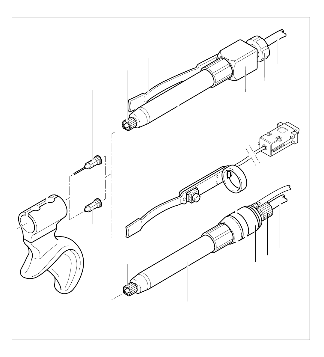
The numbers printed in bold in the text refer to the corresponding position numbers in the illustration
on the front fold-out page (see Section 2.1).
Instruction steps in the illustrations are
indicated with arrows.
When several instruction steps are
indicated in an illustration, the shading of
the arrow has the following meaning:
Black arrow = 1st step
Grey arrow = 2nd step
White arrow = 3rd step
1.2 Items Supplied
1 Hand-held Applicator 97111 (mechanical) or
Hand-held Applicator 97112 (pneumatic footswitch) or
Hand-held Applicator 97116 (fingerswitched);
1 Pencil Holder;
Accessory Items;
1 Needle Kit;
1 Instruction Manual.
☞
As a result of technical development, the illustrations and descriptions in this instruction manual can
deviate in detail from the actual unit delivered.
1

Please observe the following1
1.3 For Your Safety
For safe and successful operation of the unit, read these instructions completely.
If the instructions are not observed, the manufacturer can assume no responsibility.
● Observe general safety regulations for the handling of chemicals!
● Observe manufacturer’s instructions! Request a safety data sheet for the product used!
● When working with pressurized air, wear protective glasses!
1.4 Usage
The Hand-held Applicators are suitable for dispensing Loctiteproducts in a manual or semiautomatic process.
This ergonomically designed applicator provides hand comfort and application control to eliminate
hand fatigue and improve dispensing accuracy.
The applicators can be used in a hand-held fashion or mounted in a stationary manner that allows
easy production line integration for fulfilling your dispensing needs.
Loctite provides a selection of product reservoirs that could be used with the various Hand-held
applicators that are available.
Description2
2.1 Operating Elements and Connections
☞
2
● Fold out the illustration inside the front cover!
97111
1 Pistol grip
2 Dispensing needle
3 Luer-Lok tip cap
4 Luer-Lok adapter
5 Manual actuator assembly with trigger lever
6 Valve assembly with 6.3 mm product feedline
7 Adjustment knob (for the stroke of the shutoff piston)
 Loading...