

Loctite 97008, 97007, 97010, 97009 Operating Manual

Operating Manual
Bedienungsanleitung
2 l Semi-Automatic Dispense System
2 l-Halbautomatisches Dosiersy stem
97007/97008/97009/97010

2

3
English......................................................................................................................6-28
Deutsch...................................................................................................................29-53

4
Contents
1 Please observe the following......................................................................................6
1.1 Emphasized Sections.....................................................................................................6
1.2 Items Supplied................................................................................................................6
1.3 For Your Safety ..............................................................................................................7
1.4 Field of Application (Intended Usage) ............................................................................8
2 Description....................................................................................................................9
2.1 Theory of Operation........................................................................................................9
2.2 Operating Elements and Connections..........................................................................10
3 Technical Data............................................................................................................13
3.1 Energy Requirements...................................................................................................13
3.1.1 Electric’s.......................................................................................................................13
3.1.2 Pneumatics...................................................................................................................13
3.2 Connections and Dimensions.......................................................................................13
3.3 Other Data....................................................................................................................14
3.4 Safety Device ...............................................................................................................14
4 Installation ..................................................................................................................14
4.1 Environmental and Operating Conditions.....................................................................14
4.2 Space Requirements....................................................................................................15
4.3 Connecting the Unit......................................................................................................15
5 Dispensing..................................................................................................................15
5.1 First Operation..............................................................................................................15
5.2 Filling and Refilling the Product Reservoir....................................................................16
5.3 Adjusting the Dispensed Quantity ................................................................................17
5.3.1 Time Controlled Mode..................................................................................................17
5.3.2 Continuous Mode.........................................................................................................18
5.4 Shutdown for Longer Periods of Non-use ....................................................................19
5.5 Returning to Operation after Longer Periods of Non-use.............................................19

5
Contents
6 Care and Maintenance............................................................................................... 19
7 Troubleshooting ........................................................................................................ 20
7.1 Troubleshooting...........................................................................................................20
7.2 Replacing the Rupture Disk......................................................................................... 22
8 Special Adjustments (for Service Personal only)................................................... 23
8.1 Adjusting the Level Sensor (only 97009).................................................................... 23
8.2 External Connection Empty Signal (only 97009) ........................................................ 24
9 Annex..........................................................................................................................25
9.1 Spare Parts.................................................................................................................. 25
9.2 Pin assignment............................................................................................................26
9.3 Declaration of EC Conformity......................................................................................28

6
1 Please observe the following
1.1 Emphasized Sections
Warning!
Refers to safety regulations and requires safety measures that protect the operator or other
persons from injury or danger to life.
Caution!
Emphasizes what must be done or avoided so that the unit or other property
is not damaged.
Notice
Gives recommendations for better handling or adjustment of the unit during operation as well as
for service activities.
The numbers printed in bold in the text refer to the corresponding position numbers in the
illustration on page 10-12.
• The point emphasizes an instruction step.
Instruction steps in the illustrations are
indicated with arrows.
When several instruction steps are indicated in
an illustration, the shading of the arrow has the
following meaning:
Black arrow = 1st step
Grey arrow = 2nd step
White arrow = 3rd step
1.2 Items Supplied
– Semi-automatic Dispense System
– Foot switch (97007 and 97010 only)
– Tube “Silicone Grease”
– Bottle nesting basket (97009 only)
– Drip cup (3)
– Power cord
– Operating manual
As a result of technical development, the illustrations and descriptions in this instruction manual
can deviate in detail from the actual unit delivered.
7
1 Please observe the following
1.3 For Your Safety
For safe and successful operation of the unit, read these instructions completely. The
manufacturer cannot be held responsible for damage or injury of any kind because of misuse or
improper application or because of failure to observe safety instructions or warnings.
Be sure to retain this manual for future reference.
Request the technical data sheet and the safety data sheet (acc. to the EC Directive 91/155/EC)
for the LOCTITE
®
-product used at
Henkel Loctite Deutschlan d GmbH
www.loctite.com for US and Canada version of data sheets
+49 89 92 68 11 67 for English version of data sheets;
089-92 68 11 22 for German version of data sheets.
FOLLOW UNCONDITIONALLY THE INSTRUCTIONS OF THESE DATA SHEETS!
If chemical products are not properly handled, damage to health can result!
Observe general safety regulations for the handling of chemicals!
Observe manufacturer’s instructions!
Request a safety data sheet for the LOCTITE-product used!
When working with pressurized air, wear protective glasses!
Damage to the power cord or the housing can result in contact with live electrical parts.
Check the power cord and the unit before each use.
If the power cord or the unit is damaged, do not operate!
Replace a damaged power cord with a new one.
The unit may be opened and repaired only by an authorized service personal.
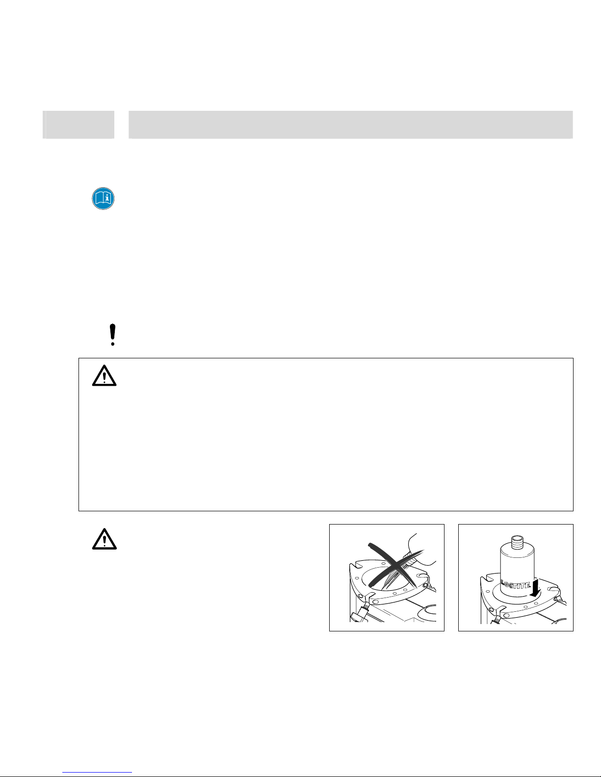
Never fill the product directly into the
Product Reservoir!
The pneumatic safety devices would
become clogged and therefore
ineffective!
Insert only products packaged in
original LOCTITE containers!

8
1 Please observe the following
1.4 Field of Application (Intended Usage)
The Semi-automatic Dispense System is suitable for the exact application of LOCTITE products
at manual workstations such as in workshops, laboratories and industrial installations.
It is designed for a product application position.
– The Semi-automatic Dispense System 97010 is equipped with precision pressure regulator
0-1 bar (0-15 PSI).
– The Controller 97007 is equipped with a pressure regulator 0-8 bar (0-115 PSI).
– Both, 97008 and 97009 are equipped with a precision pressure regulator
0-4 bar (0-60 PSI).
– The Controller 97009 additionally has a low level sensor.
With the Semi-automatic Dispense System, anaerobic, UV curing and cyanoacrylate adhesives
can be dispensed.
The capacity of the integrated reservoir is:
– 500 gr. bottle for CA Products – 1 lb. bottle
– 250 ml bottle for Anaerobics – 1 Liter bottle
– Bottle with a ø 124 mm and – 2 kg bottle
a height of 250 mm

9
2 Description
2.1 Theory of Operation
The Semi-automatic Dispense System is connected to an external pneumatic supply. It regulates
the adjusted dispensing pressure and controls the dispensing during the selected dispensing
time.
An uncovered bottle of LOCTITE product is placed directly into the integrated reservoir, and the
reservoir lid is clamped in place.
It is then pressurized using clean, filtered dry air. Air within the reservoir will push down on the
liquid in the bottle and force it through the product feedline to the dispensing valve.
The amount of product dispensed is controlled by three main factors:
– Amount of pressure in the reservoir
– Length of time the dispensing valve remains open
– Dispensing needle size
Additional Features (97009 only)
Two additionally features are available from batch no. 2FFE0001.
EMPTY:
If the reservoir is empty the contact of the level sensor opens. A beeping tone indicates the
message and the sign “U” is displayed.
READY:
If the dispensing cycle is finished and the reservoir is not empty closes a contact.
Both signals are available as dry contacts at the XS 1 start interface for optional connection to a
higher-ranking controller or a warning light.
The start of a dispensing cycle is not locked when EMPTY is indicated.
Pay attention if cyanoacrylate is dispensed – Air in the feedline results in curing of the product!
When the user quits the EMPTY message and the beeping tone with the button ENTER the
signal at the interface XS 1 is quit, too.
The READY signal will only be indicated, when the reservoir is refilled and the sensor is
activated.
 Loading...