

Loctite 883976 Operation Manual
EQUIPMENT
Operation Manual
Loctite
Part Number 883976
Benutzerhandbuch
Loctite Digitales
Kartuschendosiergerät
Artikelnummer 883976
Digital Syringe Dispenser
Manual de operación
Loctite Dosificador
digital tipo jeringa
Número de parte 883976

Table of Contents 2
1. Safety - Please Observe the Following 3
1.1 Emphasized Sections
1.2 For Your Safety
1.3 Unpacking and Inspection
1.4 Items Supplied
2 Description 4
3 Technical Data 6
4 Installation 6
5 Operation 7
5.1 Set up Instructions
Manual Mode
5.2 Dispense Cycle Setting
Time Mode
Incremental Mode with Teach Function
Cycle Counter Reset
6 Troubleshooting 10
7 Maintenance & Operational Tips 11
8 Accessories and Spare Parts 11
9 I/O Configuration & Pneumatic Diagram 12
10 Warranty 13
11 Declaration of Conformity 15
2
1 Please Observe The Following
1.1 Emphasized Sections
Warning!
Refers to safety regulations and requires safety measures that
protect the operator or other persons from injury or danger to
life or property
Caution!
Emphasizes what must be done or avoided so that the unit or
other property is not damaged.
Notice:
Gives recommendations for better handling of the unit
during operation or adjustment as well as for service
activities.
1.2 For Your Safety
For safe and successful operation of the unit, read these
instructions completely. If the instructions are not observed,
the manufacturer can assume no responsibility.
Do not operate the unit in excess of rated capacities.
Do not use the unit to dispense flammable or corrosive
fluids.
Do not use in wet or exposed environments.
Observe general safety regulations for the handling of
®
chemicals such as Loctite
adhesives and sealants. Observe
the manufacturer’s instructions as stated in the Material
Safety Data Sheet (MSDS).
Make sure the Unit stands stable and secure.
3

1.3 Unpacking and Inspection
Carefully unpack the Loctite® Digital Syringe
Dispenser and examine the items contained in the
carton. Inspect the unit for any damage that might
have occurred in transit. If such damage has
occurred, notify the carrier immediately. Claims for
damage must be made by the consignee to the carrier
and should be reported to the manufacturer.
1.4 Items supplied
(1) Digital Syringe Dispenser 883976
(1) Universal Power Cord and Adapter
902520
(1) Foot Switch 902521
(1) Syringe Stand 901459
(1) 10ml and (1) 30ml Airline Adapter
(1) Dual Unit Stacking Lock Pin 8900574
(1) Air line Support Mast 8900575
(1) Needle Sample Kit
(1) Inlet Air Hose (6mm OD x 6ft) & Fitting
Kit 902523
2 Description
The Loctite® Digital Syringe Dispenser 883976 is semi
automatic dispensing system designed for adhesives and
fluids packaged in syringe barrels. The unit has digital
timing control, with decimal control to .001 seconds for
increased precision over typical pressure time systems. An
adjustable pressure regulator controls a pulse of air, and
when used in conjunction with a airline adapter attached to
an adhesive syringe barrel, it will provide a controlled
dispense of that adhesive. Additional features include
Vacuum suck-back that can effectively control
product dripping or stringing.
4
Timed or Incremental Mode to allow adhesive to be
applied at once or in an incremental fashion.
Convenient “Teach Mode” to help determine time
required when the dispense amount is not known.
Cycle counter option displays clearly in LCD screen
The unit can also be integrated into PLC
programming to facilitate a continuous operation.
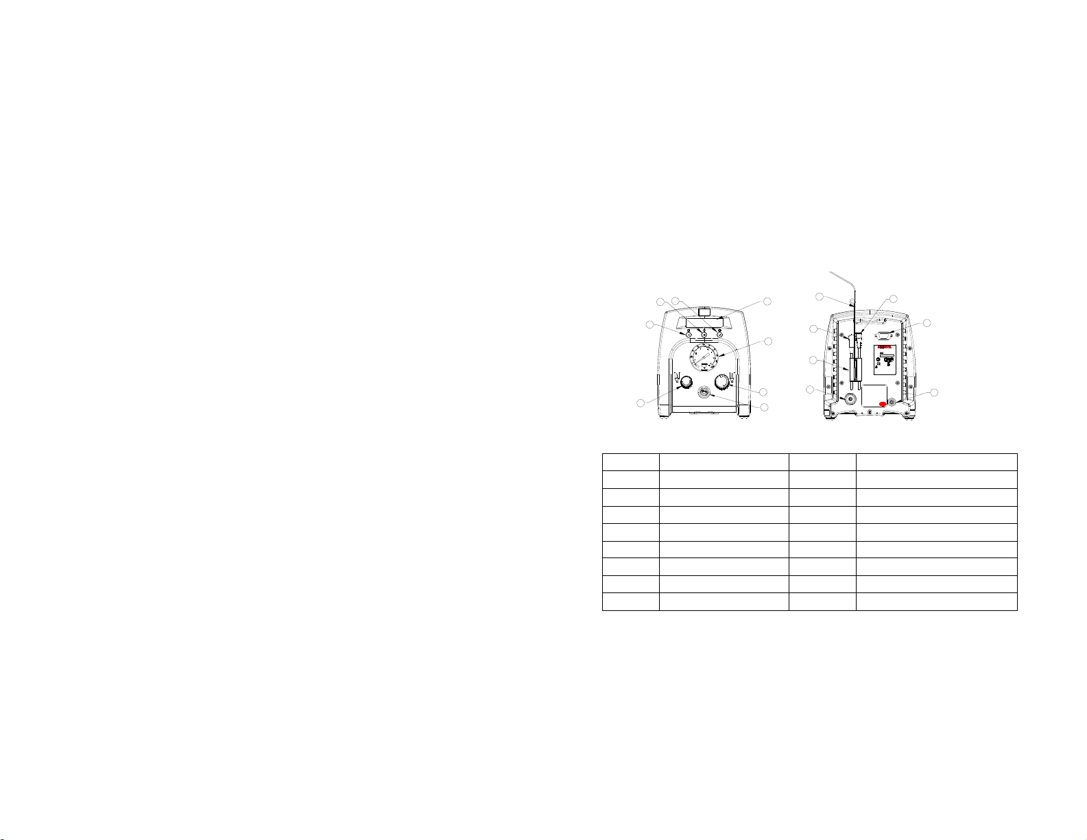
2.1 Feature Descriptions
3
2
1
4
5
8
6
7
9
10
15
Corporation Contact Locations
For North America:
14
Henkel Corporation
One Henkel Way
Rocky Hill, CT 06067
For Other Worldwide Locations:
Henkel AG & Co. KGaA
Site Munich
Gutenbergstr. 3
85748 Garching
Germany
Label # 8900577
Items Description Items Description
1
2
3
4
5
6
7
8
Power Button
Mode Button
Set up/Save Button
Display
Air Pressure Gauge
Air Pressure Regulator
Pulsed Air Outlet
Vacuum Control
9
10
11
12
13
14
15
Receiver head air hose mast
Foot Switch Receptacle
Power Receptacle
I/O Connection
Exhaust Port
Air Inlet
Cord Lock
Fig 2.1
Digital Syringe Dis p en ser
Item # 98666
24V
S/N:
Pro
S
m
t
y
d
e
uct
onit
f
a
t
ed
or
ion
S
t
es
ed
VT
U
PRODUCT SERVICE
NRTL
C
US
CAUTION:
Please refer to the instruction
manual before installation
MADE IN CHINA
www.equipment.loctite.com
11
12
10W 100PSI
VU
T
SUD
geprufte
Sicherheit
13
5
3 Technical Data
)
152mm X 165mm X
Size
Weight 1.2 kg (2.6lbs
Minimum
Dispense
Time
Input Voltage 24VDC Vacuum 406mm (16”) of Hg
Rated Power 10W Timer 0.020 – 60.000 seconds
Air Input 100 psi (6.9 bars) Max. Cycle Mode Timed, Incremental, Manual
Pollution
Degree
Installation
Category
Indoor Use
Operating
Temperature
178mm
(6” X 6.5” X 7.0”)
0.020 Seconds
II
I
Altitude up to 2,000m
(6,562ft)
0˚C to 50˚C (32˚F to
122˚F)
Max.
Relative
Humidity
Air Output 0-100 psi (0-6.9 bars)
Maximum
Dispense
Time
Timing
Repeat
Tolerance
Cycle Rate 600 cycles/min
LCD 16 X 2 display segments
Storage
Temperature
80% for temperature up to
31˚C (87.8˚F) Decreasing
linearly to 50% relative
humility at 40˚C (104˚F)
60.000 seconds
+/- 0.001%
-10˚C to 60˚C (14˚F to
140˚F)
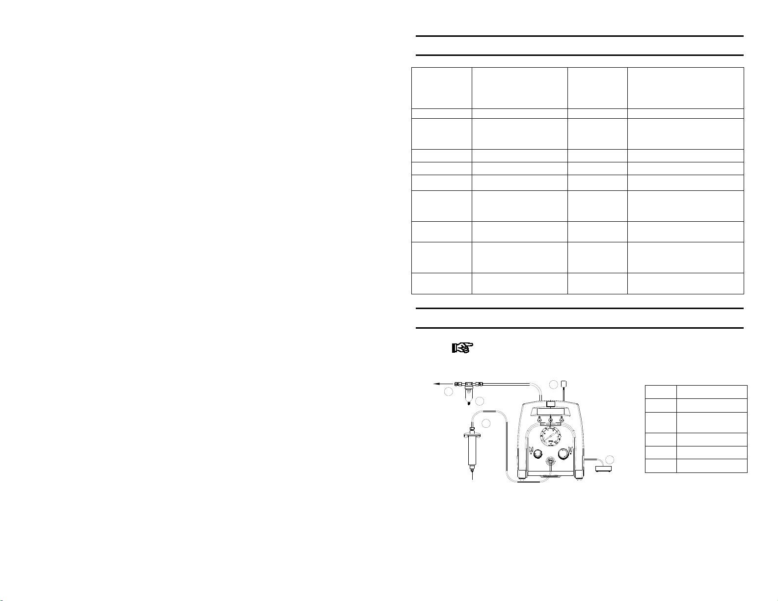
4 Installation
Use 5 micron Filter –Regulator –Loctite 985397 or
equivalent for inlet air supply
1
2
5
3
4
Items Description
1 To Air Source
Air Filter –sold
2
3 Power Adapter
4
5 Syringe Adapter
separately
Foot Switch
Fig. 4.1
4.1 10ml or 30ml syringe adapter attaches to Pulsed Air
Outlet (7) and syringe barrel.
6

5 Operation
5.1 Set up Instructions – Manual Dispense Cycle Setting
The Manual Mode allows the unit to pulse for the duration
that the foot switch is depressed. It is typically used to start up and
purging through a dispense needle.
The unit is factory pre-set with a dispense time of 0.1
seconds. Manual mode will not function unless there is time set
in the time display. (00.000 time setting will not allow the unit to
dispense in manual mode)
5.1.1 Turn on the unit by pressing the Power button (1).
5.1.2 Press the Mode button (2) until Manual Mode appears
on the display.
5.1.3 Turn up the air pressure by rotating the Air Pressure
Regulator knob (6) until the desired pressure is indicated on
the Air Pressure Gauge (5).
5.1.4 After filling the barrel or using pre-packaged adhesive,
attach the syringe to the syringe adapter. Make certain that
the syringe locks into place.
5.1.5 Connect the plug end of the receiver head assembly to
the Air Dispense Outlet (7).
5.1.6 If vacuum “suck back” is needed, rotate the Vacuum
Regulator (8) counter clockwise until the desired vacuum
pressure is obtained.
5.1.7 Press and hold the Footswitch to activate the dispense
cycle. (The Manual Mode is now activated)
5.2 Dispense Cycle Setting – See Figure 5.1
Push the Mode button (2) to select Timed Mode or
Incremental Mode.
Timed Mode: Allows the unit to dispense for the
the complete amount of time set on the timer
when the foot switch is initiated
Incremental Mode: Allows the unit to dispense
for as long as the foot pedal is depressed and will
continue till the set time is reached. This allows a
7

5.2.1 Setting the Timer in the Timed Mode
5.2.1.1 From the Timed Mode , press and hold button the
5.2.1.2 Pressing the Set button (3) from this point moves
5.2.1.3 Press the (+) and (-) button to set the time for
5.2.1.4 When your desired time has been entered, press
5.2.2 Setting the Timer in the Incremental Mode
5.2.2.1 From the Incremental Mode, press and hold the
5.2.2.2 Press and hold down the foot switch. Product
5.2.2.3 Press and hold the Set button (3) for two seconds
pre-determined amount of product to be
incrementally added in steps if desired.
Set button (3) for 2 seconds. The unit will enter
the Set- up Mode and allow each or the time
digits to be set.
the the cursor to the next digit and back till the
desired time has been set
each digit desired. (You can not go past 0 with
either button.) Minimum dispense time is 00.020
seconds
and hold the Set button (3) for two seconds to
save the data.
Setting the timer from the Incremental mode, “Teach
Mode” is helpful in determining dispense time
required when dispense output is unknown. The timer
will continue to accumulate time as long as the foot
pedal is depressed, allowing the user to “teach” the
unit the exact time needed
Set button (3) to enter the “Teach Mode”. The
unit will still read Set-up, however the time will
show “0.000” in the LCD.
will dispense and time will accumulate. Continue
to release and press the foot switch till the desired
quantity has been dispensed.
to save the data.
8

5.2.2.4 Press the Mode button (2) to switch the Timed or
Incremental Mode as desired. The dispenser is
now ready to dispense this new time cycle
5.2.3 Resetting the Cycle Counter
The cycle counter records the numbers of automatic
dispense cycles being activated. Up to 65,535 cycles
can be recorded. This number is shown at the lower
right hand corner of the LCD. To reset the counter;
5.2.3.1 Press and hold the Set button (3) for two seconds
to enter the Set up mode.
5.2.3.2 Then re-press and hold the Set button (3) for three
to five more seconds to reset the counter. After
two seconds the screen will first show “Saving
Data” but continue holding till the cycle counter
resets to 00000 .
Prog
POWER
MODE
Counter
Time
SET
MODE
SETUP MODE
2.25
P1 00004
SETUP MODE
22.2 5
P1 00004
TIMED MODE
P1 2.251 00004
SETUP MODE
22.2 5
P1 00004
:Press then release
:Press and hold for approximately 4 seconds then release
OFF
TIMED MODE
2.250
P1 00004
Power ON/OFF
0
0
1
:Press and hold for approximately 2 seconds then release
Normal Operation
Setup
TIMED MODE
P1 2.250 00004
SETUP MODE
22.2 5
P1 00004
0
TIME SETTING
SETUP MODE
22.2 5
P1 00004
1
Save and Exit...
COUNTER RESET
Save and Exit...
Fig 5.1
TIMED MODE
2.250
00004
INCREMENTAL MODE
2.250
P1P100004
MANUAL MODE
*************************
Change Mode
Time setting
in TIMED mode
SETUP MODE
22.250
P1 00004
SETUP MODE
22.25
P1 00004
0
SETUP MODE
22.25
P1 00004
1
TIMED MODE
P1 2.251 00000
9

6 Troubleshooting
PROBLEM POSSIBLE CAUSE CORRECTION
LCD does not
light
System will not
actuate
System will not
pressurize
System will not
pull vacuum
Inconsistent
dispensing
No power input
Foot switch not
plugged in or
improperly plugged
in
Defective foot switch
Broken wire or loose
connection inside
unit
Defective solenoid
Defective PC board
Insufficient air
pressure
Air hoses not
plugged in
Regulator defective
Vacuum setting is
too low
Defective solenoid
Defective vacuum
venturi
Defective vacuum
needle valve
Air bubbles in
adhesive
Dispense time is too
low
Dispense needle
started to clog
Check power cord
connections
Turn on power
Check foot switch
connection
Foot switch needs to be
repaired or replaced
Unplug power cord and
disconnect air supply.
Remove cover and check
for broken wires or loose
connections
Replace solenoid
Replace PC board
Increase air supply
pressure
Check connection
Replace regulator
Increase vacuum setting
Replace solenoid valve
Replace venturi
Replace needle valve
Reduce vacuum setting
Increase dispensing time
Replace needle
10
7 Maintenance & Operational Tips
Use Loctite® Universal Power Supply 902520 only.
Always disconnect the power supply before servicing the unit.
If using to dispense from syringes without pistons,
optional In-Line Filter 984650 should be installed with the
Air Line Adapter to prevent fluids from entering the unit
Use 5 micron Filter –Regulator –Loctite 985397 or
equivalent for inlet air supply
The dispenser is designed and built to be relatively
maintenance free. To assure trouble free operation, the
following recommendations should be followed:
1. Make certain air supply is clean and dry.
2. When not in use turn vacuum off or disconnect air supply
to unit. Failure to do so could result in adhesive being
pulled back into the unit and rendering it non-functional.
3. Avoid turning barrels upside down or laying barrel so
that material may run through airline to internal
components.
4. Avoid connecting air supply exceeding 100 psi (6.9 bars)
5. Use only Amyl Alcohol to clean outside surface of the
main housing.
6. Use only soft cloth to clean the LCD.
While under warranty, the unit may be
repaired only by an authorized Henkel service
representative.
8 Accessories and Spare Parts
Universal Power Cord and Adapter 902520
Foot Switch 902521
Syringe Stand 901459
Dual Unit Stacking Lock Pin 8900574
Air line Support Mast 8900575
6mm Inlet Air Tubing (10 meters) 902523
11
Needle Kits and Air Line Adapters – check Disposable
Dispense Components listing at
www.equipment.loctite.com
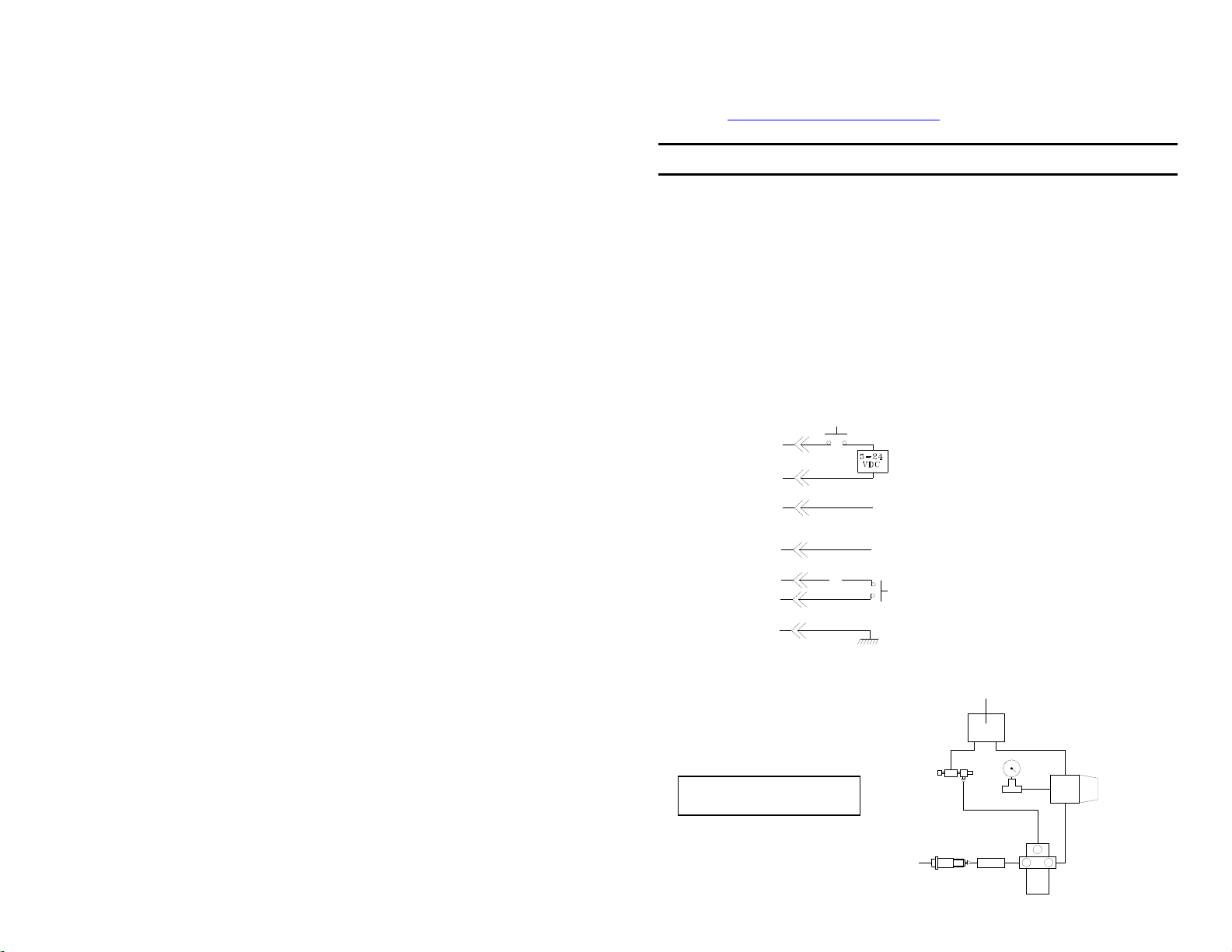
9 I/O Configuration & Pneumatic Diagram
Upon completion of a dispense cycle, an open collector circuit
closes and remains closed until the next dispense cycle. This
circuit can be used to signal back to a host computer, start
another device in sequence, or drive any other operations that
need to be tied to the completion of the dispense cycle. Upon
closure, (end of dispense cycle), power from an external source
is allowed to pass through the circuit to operate a 5 to 24 VDC
load. Power consumption must not exceed 250 mA. The load
could be a relay, solenoid, counter, LED, or any device that will
operate within a 5 to 24 VDC range and a maximum of 250 mA.
PIN 1
PIN 2
PIN 3
PIN 4
PIN 5
PIN 6
PIN 5
Pin 7, 8 and 9 = available
Pneumatic Diagram
To init ia te a dispense cy cle
During cycle = GRO U N D
End of cycle = OPEN
During cycle = GRO U ND
End of cycle = OPEN
To ini tia te a dispense cy cl e
with con ta c t clo su r e
Chasis Ground
NEEDLE VALVE
AIR OUTLET
AIR INLET
AIR MANIFOLD
PRESSURE REGULATOR
3
21
SOLENOID VALVE
12

10 Warranty
Henkel expressly warrants that all products referred to in this
Instruction Manual for the Loctite
Dispesner (hereafter called “Products”) shall be free from defects in
materials and workmanship. Liability for Henkel shall be limited, as
its option, to replacing those Products which are shown to be
defective in either materials or workmanship or to credit the
purchaser the amount of the purchase price thereof (plus freight and
insurance charges paid therefor by the user). The purchaser’s sole
and exclusive remedy for breach of warranty shall be such
replacement or credit.
A claim of defect in materials or workmanship in any Products shall
be allowed only when it is submitted in writing within one month
after discovery of the defect or after the time the defect should
reasonably have been discovered and in any event, within (12)
months after the delivery of the Products to the purchaser. This
warranty does not apply to perishable items, such as, but not limited
to: (o-rings, seals, washers, filters, lights, etc.). No such claim shall
be allowed in respect of products which have been neglected or
improperly stored, transported, handled, installed, connected,
operated, used or maintained. In the event of unauthorized
modification of the Products including, where products, parts or
attachments for use in connection with the Products are available
from Henkel, the use of products, parts or attachments which are not
manufactured by Henkel, no claim shall be allowed.
No Products shall be returned to Henkel for any reason without prior
written approval from Henkel. Products shall be returned freight
prepaid, in accordance with instructions from Henkel.
NO WARRANTY IS EXTENDED TO ANY EQUIPMENT
WHICH HAS BEEN ALTERED, MISUSED, NEGLECTED, OR
DAMAGED BY ACCIDENT, OR IF THE SYSTEM WAS USED
TO DISPENSE ANY LIQUID MATERIAL OTHER THAN
LOCTITE® PRODUCTS.
®
883976 Digital Syringe
13

EXCEPT FOR THE EXPRESS WARRANTY CONTAINED IN
THIS SECTION, HENKEL MAKES NO WARRANTY OF ANY
KIND WHATSOEVER, EXPRESS OR IMPLIED, WITH
RESPECT TO THE PRODUCTS.
ALL WARRANTIES OF MERCHANTABILITY, FITNESS FOR
A PARTICULAR PURPOSE, AND OTHER WARRANTIES OF
WHATEVER KIND (INCLUDING AGAINST PATENT OR
TRADEMARK INFRINGEMENT) ARE HEREBY DISCLAIMED
BY HENKEL AND WAIVED BY THE PURCHASER.
THIS SECTION SETS FORTH EXCLUSIVELY ALL OF
LIABILITY FOR HENKEL TO THE PURCHASER IN
CONTRACT, IN TORT OR OTHERWISE IN THE EVENT OF
DEFECTIVE PRODUCTS.
WITHOUT LIMITATION OF THE FOREGOING, TO THE
FULLEST EXTENT POSSIBLE UNDER APPLICABLE LAWS,
HENKEL EXPRESSLY DISCLAIMS ANY LIABILITY
WHATSOEVER FOR ANY DAMAGES INCURRED DIRECTLY
OR INDIRECTLY IN CONNECTION WITH THE SALE OR USE
OF, OR OTHERWISE IN CONNECTION WITH, THE
PRODUCTS, INCLUDING, WITHOUT LIMITATION, LOSS OF
PROFITS AND SPECIAL, INDIRECT OR CONSEQUENTIAL
DAMAGES, WHETHER CAUSED BY NEGLIGENCE FROM
HENKEL OR OTHERWISE.
14
11 Declaration of Conformity
Conforms with the protection requirements of Council Directive
89/336/EEC, relating to Electromagnetic Compatility by the
appication of the following EMC Standards:
EN61326 / A3:2003
IEC61000-3-2:2000
IEC61000-3-3/A1:2001
Conforms to Council Directive 72/23/EEC (Low Voltage
Directive) by the application of the following standard:
IEC61010-1:2001 (2nd Edition)
Complies to RoHS Directive 2002/95/EC given by The
European Parliament and The Council of 27 January 2003 on the
restriction of the use of certain hazardous substances in electrical
and electronic equipment
Complies to European Waste Electrical and Electronic
Equipment (WEEE) Directive 2002/96/EC
Meets the requirements of the German Equipment and Product
Safety Act
Conforms to the following certification marks:
15

Henkel Corporation
Engineering
Adhesives
USA
Henkel Corporation
One Henkel Way
Rocky Hill, CT 060673910
For all world wide
locations
Visit www.loctite.com
Canada
Henkel Canada
Corporation
2515 Meadowpine
Boulevard
Mississauga, Ontario L5N
6C3
Canada
For Equipment in North
America visit
www.equipment.loctite.com
Mexico
Henkel Capital, S.A. de C.V.
Blvd Magnocentro No8 Piso 2
Interlomas
52760, Huixquilucan, Edo de
Mexico
Loctite is a registered trademark of Henkel Corporation © Copyright 2006. All rights reserved. Data
in this operation manual is subject to change without notice
Manual P/N: 8900580, Rev D, Date: 08/07/2014
16
 Loading...