

Loctite 1390322, 1390321 Operation Manual
EQUIPMENT
Operation Manual
Loctite Integrated Semi-Automatic Dispenser
Dual Channel with Low Level Sensor
Part Numbers
1390322, 0 – 1 Bar
1390321, 0 – 7 Bar
1

Table of Contents
1. PLEASE OBSERVE THE FOLLOWING..................................................................................................... 3
1.1 EMPHASIZED SECTIONS ............................................................................................................................... 3
2. DESCRIPTION ................................................................................................................................................ 3
2.1 OPERATION.................................................................................................................................................. 3
2.3 ITEMS SUPPLIED........................................................................................................................................... 5
2.4 OVERALL DIMENSIONS................................................................................................................................6
2.5 CONTROL PANEL (FRONT & BACK OF CONTROLLER).................................................................................. 7
3. TECHNICAL DATA........................................................................................................................................ 8
3.1 SPECIFICATIONS .......................................................................................................................................... 8
4. INSTALLATION..............................................................................................................................................9
4.1 UNPACKING AND INSPECTION...................................................................................................................... 9
4.2 ENVIRONMENTAL AND OPERATING CONDITIONS ........................................................................................ 9
4.3 CONNECTING THE UNIT ............................................................................................................................... 9
5. OPERATION.................................................................................................................................................. 10
5.1 FUNCTION OF THE CONTROL PANEL:......................................................................................................... 10
5.2 XS1 CONNECTION SIGNAL: ....................................................................................................................... 11
5.3 START UP THE SYSTEM: ............................................................................................................................ 11
5.4 RUN: AUTO MODE...................................................................................................................................... 11
5.5 RUN: MANUAL MODE ................................................................................................................................11
5.6 RUN: CONTINUOUS MODE.......................................................................................................................... 12
5.7 SET: TIME (AUTO) MODE .......................................................................................................................... 12
5.8 SET: DELAY (AUTO) MODE ....................................................................................................................... 12
5.9 SET: OUTPUT MODE .................................................................................................................................. 12
5.10 SET: LOW LEVEL MODE ............................................................................................................................ 13
5.11 SET: LOCK-OUT MODE.............................................................................................................................. 13
5.12 ADJUST THE LEVEL SENSOR ...................................................................................................................... 13
6. TROUBLESHOOTING................................................................................................................................. 14
7. CARE AND MAINTENANCE...................................................................................................................... 15
7.1 CARE ......................................................................................................................................................... 15
7.2 MAINTENANCE .......................................................................................................................................... 15
8. DOCUMENTATION ..................................................................................................................................... 16
8.1 ELECTRICAL SCHEMATIC........................................................................................................................... 16
8.2 PIN CONNECTIONS..................................................................................................................................... 18
9. ACCESSORIES, SPARE PARTS & SYSTEM COMPONENTS SOLD SEPARATELY......................19
2

1. Please Observe The Following
1.1 Emphasized Sections
Warning!
Refers to safety regulations and requires safety measures that protect the operator or other
persons from injury or danger to life.
Caution!
Emphasizes what must be done or avoided so that the unit or other property is not damaged.
Notice:
Gives recommendations for better handling of the unit during operation or adjustment as well as
for service activities.
Warning!
Never fill the product directly into the Product Reservoir! Insert only products packaged in
original Loctite® containers!
2. Description
2.1 Operation
The Loctite® Integrated Semi-Automatic Dispenser combines a dual channel dispense
controller and reservoir into a single system. The controller provides 2 independent digital
timing channels that provide control of 2 pneumatic outputs. These outputs can be used to
control dispense valves, advancing slides or any other pneumatic device. The controller can be
actuated either by a footswitch, finger switch or external signal. It is capable of operating in a
manual or time mode for dot or bead dispensing applications. The reservoir can accommodate
50ml, 250 ml, 500 gram, 1 liter, 2 kg and 200 gram adhesive packages which deliver adhesive
to dispensing valves. The system is also equipped with low level sensor which can notify the
operator that the adhesive package needs to be replaced.
- The Integrated Semi-Automatic Dispenser 1390322 is equipped with a precision pressure
regulator 0-1 bar (0-14 PSI).
- The Integrated Semi-Automatic Dispenser 1390321 is equipped with a pressure regulator 0-
7 bar (0-100 PSI).
With the Integrated Semi-Automatic Dispense System, anaerobic, UV Curing and
cyanoacrylate adhesive can be dispensed.
The capacity of the Integrated Semi Automatic Dispenser is:
- 500 gr. bottle for CA Product - 1 lb. bottle
- 250 ml bottle for Anaerobics - 1 Liter bottle
- Bottle with a Ø 124mm and - 2kg bottle
a height of 250mm
3

2.2 Theory of Operation
The Loctite® Integrated Semi-Automatic Dispenser is connected to an external pneumatic
supply. It regulates the adjusted dispensing pressure and controls the dispensing during the
selected dispensing time.
®
An uncovered bottle of LOCTITE
product is placed directly into the integrated reservoir, the
tube is inserted into the product, and the reservoir lid is clamped in place.
It is then pressurized using clean, filtered dry air. Air within the reservoir will push down on
the liquid in the bottle and force it through the product feed line to the dispensing valve.
The amount of product dispensed is controlled by three main factors:
– Amount of pressure in the reservoir
– Length of time the dispensing valve remains open
– Dispensing needle size
Time Mode:
1. Press the footswitch to activate the system.
2. The dispensing timer will be activated and start to dispense with preset dispensing time.
3. After the dispensing timer has reached the preset dispensing time, the dispensing will be
stopped.
Manual Mode:
1. Press the footswitch to activate the system.
2. The system will start to dispense and the dispensing timer will start to count the
dispensing time.
3. Once the footswitch is released, the dispensing will be stopped.
Additional Features:
EMPTY Signal:
If the reservoir is empty the contact of the level sensor opens. Three different types of Empty
Signal can be selected to indicate.
Mode 1: Digital Only
Mode 2: Digital + Lamp
Mode 3 : Digital + System Stop
READY Signal :
If the dispensing cycle is finished and unit is not dispensing, a contact is closed and a
<READY> signal is communicated. The ready signal only indicates that the dispensing is either
on (busy) or off (ready). This signal is independent of any other system conditions.
Both EMPTY and READY signals are available as dry contacts at the XS1 start interface for
optional connection to an external PLC. Any external sources need to be programmed to suit
end user requirements.
In Mode 3, the ready signal will be communicated even though an Empty signal may be
communicated, however, the system will not dispense.
4

Caution!
Pay attention if cyanoacrylate is dispensed – Air in the feed line results in curing of the product!
2.3 Items Supplied
- Integrated Semi-Automatic Dispenser, Dual Channel, 0-1 Bar, Order No. 1390322 or
- Integrated Semi-Automatic Dispenser, Dual Channel, 0-7 Bar, Order No. 1390321
- Footswitch (1)
- Reservoir Fitting (1)
- Bottle Nesting Basket (1)
- Anti-Bubbler Fitting and Tubing Kit
- ¼” NPT to 6mm tube connector (1)
- Power Adapter with Cord (1)
- Operating Manual CD (1)
5
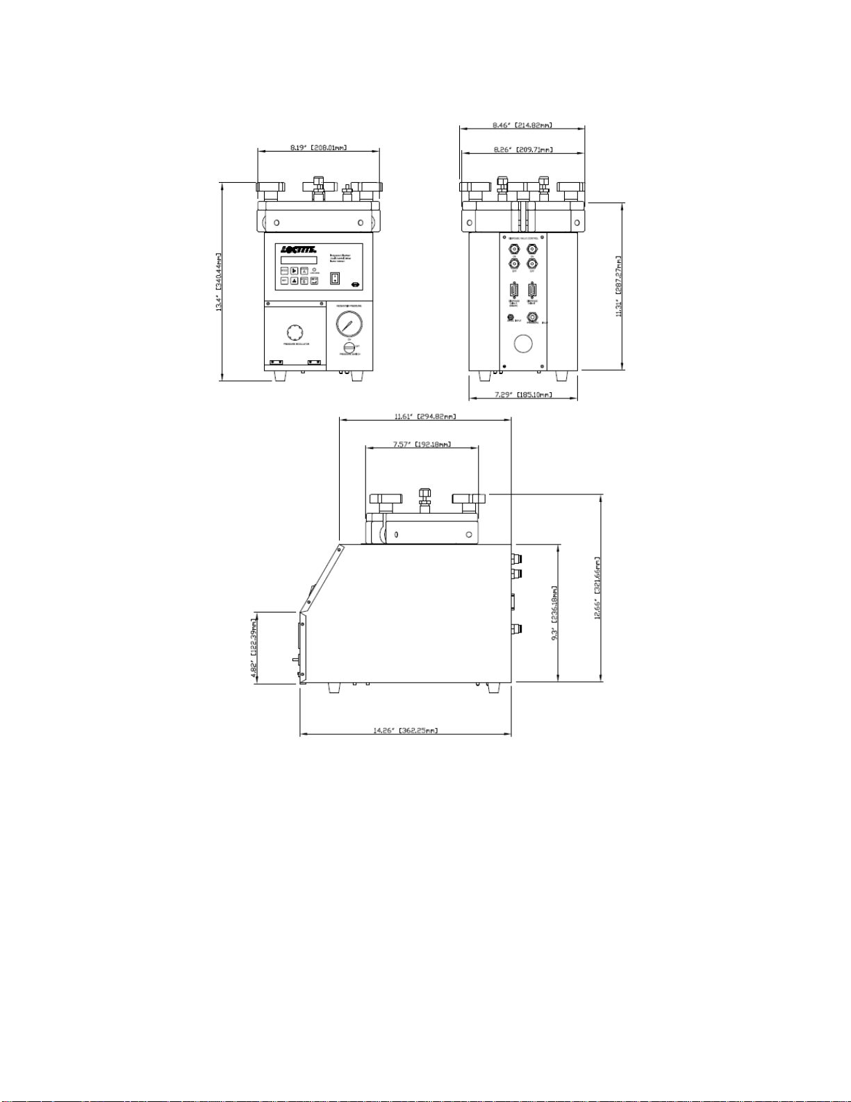
2.4 Overall Dimensions
6
 Loading...