

Page 1
SL-DC-I-O Rev A
Solar Differential Control
Installation and Operation
Manual
WARNING:
This manual must only be used by a qualified heating
installer/service technician. Read all instructions,
before installing. Perform steps in the order given.
Failure to comply could result in severe personal
injury, death, or substantial property damage.
Page 2

Contents
HAZARD DEFINITIONS .................................................... 2
1. INTRODUCTION
Application and Safety Instructions ................................... 3
Main Characteristics ........................................................... 4
Technical Characteristics ................................................... 4
Display ............................................................................. 5-6
2. SERVICE
Language ........................................................................... 7
Time and Date .................................................................... 7
Systems 1-8 .................................................................... 8-9
Extra ................................................................................ 10
Thermostat Function ................................................. 10
Cooling Function ....................................................... 10
Diffcontrol Function ................................................... 11
Antistagnation Function ............................................ 11
External sensor ............................................................... 12
Protection Function .................................................... 12-13
Maximum Temperature............................................. 12
Cooling/ Recooling ................................................... 13
Overheat/ Freeze Protection .................................... 13
Sensor Options . . . . . . . . . . . . . . . . . . . . . . . . . . . . . . . 14-15
Impulse Flow Meter .................................................. 14
GDS1 ........................................................................ 14
GDS2 ........................................................................ 15
Energy Measurement ...................................................... 15
Warm sensor ........................................................... 15
Cold sensor ............................................................. 16
Flow 2 ...................................................................... 16
Pump P1/ Pump P2 ........................................................ 17
Glycol and Glycol Mix...................................................... 18
Factory Setting ................................................................ 18
Reset operation time ....................................................... 18
Time graph temperature .................................................. 19
Time graph operation ...................................................... 19
Calibration Sensors ......................................................... 19
Priority Tank .................................................................... 19
P1 // P2 function in system 5 .......................................... 19
3. SETTINGS MENU
Maximum Temperature tank 1 ........................................ 20
dTMaximum tank 1 .......................................................... 20
dTMinimum tank 1 ........................................................... 20
dTMaximum return .......................................................... 20
dTFs ................................................................................ 20
dTMinimum tank 1 ........................................................... 20
Minimum rev pump .......................................................... 20
Minimum Temperature collector ...................................... 21
Maximum Temperature tank 2 ........................................ 21
dTMaximum tank 2 .......................................................... 21
dTMinimum tank 2 ........................................................... 21
Delay P2 .......................................................................... 21
Extra Functions ........................................................... 22-23
Thermostat Function ................................................. 22
Start 2 Hysteresis ..................................................... 22
Cooling Function ....................................................... 22
Cooling Hysteresis .................................................... 22
Differential Control Function ..................................... 23
Maximum cold tank ................................................... 23
Minimum warm tank ................................................. 23
Antistagnation Function ............................................. 23
Start/ Stop/ Output Option ........................................ 23
4. OPERATION MENU
Automatic and OFF operation ......................................... 24
Manual Testing ................................................................ 24
Operation Hours Menu ............................................... 24-25
Data logger “SD card” ......................................... 25-28
5. TEMPERATURES MENU .......................................... 29
6. SPECIAL FUNCTIONS.............................................. 30
Dimmer ..................................................................... 30
Security ..................................................................... 30
Others ............................................................................... 30
Notes ................................................................................ 31
Revision Notes ................................................. Back Cover
Hazard definitions
The following defined terms are used throughout this manual to bring attention to the presence of hazards of various risk levels or
to important information concerning the life of the product.
DANGER
WARNING
CAUTION
CAUTION
NOTICE
2
DANGER indicates an imminently hazardous situation which, if not avoided, will result in death or serious
injury.
WARNING indicates a potentially hazardous situation which, if not avoided, could result in death or serious
injury.
CAUTION indicates a potentially hazardous situation which, if not avoided, may result in minor or moderate
injury.
CAUTION used without the safety alert symbol indicates a potentially hazardous situation which, if not
avoided, may result in property damage.
NOTICE indicates special instructions on installation, operation, or maintenance that are important but not
related to personal injury or property damage.
Page 3

1 Introduction
SL-DC lnstallation and Operation Manual
WARNING
WARNING
WARNING
Before starting work the installer should carefully read this Installation & Operation Manual, and
make sure all instructions contained there in are understood and observed.
The Solar controller should be mounted, operated and maintained by trained personnel only.
Personnel in the course of training are only allowed to handle the product under the supervision of
an experienced fitter.
All instructions in this Installation & Operation manual should be observed when working with
the controller. Any other application shall not comply with the regulations. The manufacturer shall
not be liable in case of incompetent use of the control. Any modifications and amendments are not
allowed for safety reasons.
Application Safety Instructions
■ The Solar controller is intended for Solar heating
systems. The temperature of the water in the tank is
controlled by the temperature difference “dt” between
solar collector and tank.
■ The controller is normally used in conjunction with a
pumping station which includes a circulation pump and
a safety valve.
WARNING
Before starting work disconnect
power supply! All installation and
wiring work related to the controller
must be carried out only when
de-energized. The appliance should
be connected and commissioned by
qualified personnel only. Make sure
to adhere to valid safety regulations.
■ The controllers have been designed for use in dry
environments. For example, they are used in residential
rooms, office spaces and industrial facilities.
■ Verify that the installation complies with existing
regulations before operation to ensure proper use of the
installation.
CAUTION
WARNING
The controllers are neither splashnor drip-proof. Therefore, they must
be mounted in a dry place.
Do not interchange the connections
of the sensors and the 120V
connections under any circumstances!
Interchanging these connections
may result in life endangering electrical
hazards or the destruction of the
appliance and the connected sensors
and other appliances.
3
Page 4
1 Introduction
Main Characteristics
SL-DC Installation & Operation Manual
■ Large graphic display with backlight
■ Easy to use interface (4 keys with scroll menu)
■ Several languages available
■ Energy measuring with SD card interface to save the
recordable statistics (Temperatures, Power, Energy, Time
operation) and Parameters
■ Graphic view for temperature, power, energy, operating
time and temperature
■ 8 working systems with several extra functions possible
■ 5 inputs for temperature sensors (PT1000 type)
■ 1 logical input for impulse flow meter input
(for energy measurement)
Technical Characteristics
Table 1A Technical characteristics
Operating Temperature
Electrical Protection
Installation Category
Pollution Degree
Fusible
Power Supply
Maximum Power Consumption
(with all outputs activated)
Outputs:
P1 (Main pump with standard or PWM speed regulation)
P2 (Pump with standard or PWM speed regulation, Booster
pump, valve)
P3 (Extra, Additional heat, cooling . . . )
Inputs:
T1 (Collector 1)
T2 (Tank 1)
T3 (Extra sensor)
T4 (Extra sensor, Tank2, Collector2)
T5 (Collector return)
■ 2 analog inputs for VFS / VPS sensor inputs
(flow, pressure and temperature sensor)
■ 2 pump outputs (standard PWM) with pump exercise
function
■ 1 extra output (to control additional heat, cooling system,
differential control or anti-stagnation function )
■ Automatic, OFF or Manual test mode
■ Sensor auto checks (short circuit and breaks)
■ Collector type choice (tube or panel)
■ Collector protection (freeze or overheat)
■ Permanent memory storage
32°F - 122°F
IP20
II
2
Max T5AH250VAC
120 VAC 60Hz
4.2A (~ 504W)
Triac 1A 120 VAC.
Triac 1A 120 VAC
Relay 2A 120 VAC
PT 1000 type
PT 1000 type
PT 1000 type
PT 1000 type
PT 1000 type
T6 (Flow meter)
GDS1 (Flow meter)
GDS2 (Pressure sensor)
Sensors delivered with the product:
2 Collectors
1 Tank
1 Extra
Software Version
Impulse type (low voltage 5V)
Analog type
(VFS)
Analog type
(VPS)
PT 1000 (1.5M 356°F)
PT 1000 (3M 221°F)
PT 1000 (3M 221°F)
Displayed during the initial start-up
Version xxxxxx
4
Page 5

1 Introduction (continued)
Display
SL-DC Installation & Operation Manual
Figure 1-1 Display, keys
1: Simplified drawing of the installation.
- The logos of pumps turn when they are activated.
- The filled triangles on the valve logo indicate the circulation direction.
2: Solar system is working.
3: SD card storage is active.
4: Temperature of different sensors, Pumps speed indications, Power and Energy quantity stored.
1 2 3
T1
T3
T2
A
T1_ _ _°F
T2_ _ _°F
SD
T3_ _ _°F
T4_ _ _°F
P1_ _ _ %
_ _ _ BTU/h
4
_ _ _ BTU
A. Keypad description:
Figure 1-2 Keypad
Navigation key up or plus key
(+)
Navigation key down or minus key
Navigation key right
Navigation key left
(►)
(◄)
(-)
5
Page 6

1 Introduction
Main Menu Display
Figure 1-3 Main menu
SL-DC Installation & Operation Manual
Information
Services
Settings
Operation
Operation h
Temperatures
Press (►) to enter the navigation menu. (The title of the
active menu is high lighted in black on the top of the display.
When you enter the navigation menu you can choose
another submenu by moving the selection cursor with the
keys (+) or (-), then you can enter this submenu with ( ►).
From all menus you can press (◄) to return to the previous
menu.
-
NOTICE
IMPORTANT
To prevent mistakes after installation,
all critical parameters (system and Extra
function) are not accessible after 4 hours
power on. If you want to modify these
parameters, you must unplug and plug in
the controller. No settings are lost when
unplugging, or after a power failure.
After 4 hours you can still change all
the other parameters to optimize your
system.
Not all submenus, selection, or options
discussed in this manual are available on
all systems. The figures are representative
of what the screen on the control will
look like when the described procedures
are followed.
6
Page 7

SL-DC Installation & Operation Manual
2 Service
Languages
With (+) or (-) select the line “ENGLISH” and press ( ►) to highlight the line. Now that you can change the language with (+)
or (-), there are several choices: English, German, Dutch, Spanish, French, Italian, Portuguese, and Hungarian.
Figure 2-1 Language screen
Service---- --- -
English
Time and date
US version yes
System
Extra off
External sensor no
Protection func.
Figure 2-2 Time and Date
---
Time 6:41
Month 12
With (+) or (- ) select the line TIME and DATE and press
( ►) to enter the submenu Time and Date.
Now you can select the date and time line with (+) or
(- ), then press ( ►) to highlight the value which must
be adjusted.
NOTE: If power supply is lost, the hours will be saved
for 24 hours. After this time the clock will need to be
readjusted.
Time and Date
--- -
20 yaD
1002 raeY
Figure 2-3 U.S. version
Service---- --- -
English
Time and date
US version yes
System
Extra off
External sensor no
Protection func.
YES: °F, 12H am/pm, GPM, BTU and BTUh
NO: °C, 24H, Liter, KW and KWh
On this menu you can choose the displayed units.
7
Page 8

2 Service
SL-DC Installation & Operation Manual
Systems
When the line is selected, press ( ►) to enter the submenu. You
have the choice between 8 systems with the possibility to add
different functions.
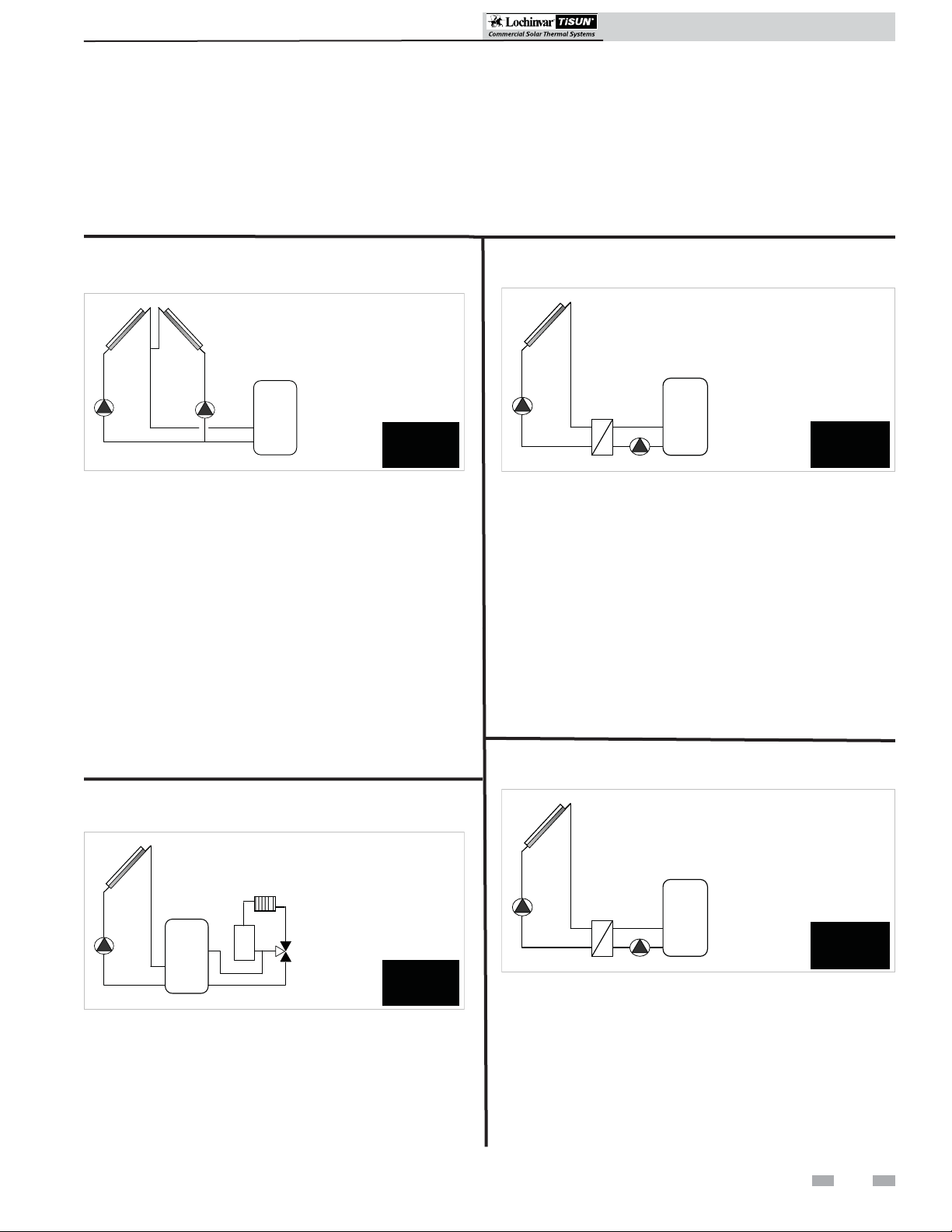
System 1
This is a basic system, with 1 tank, 1 pump, 1 collector array and
2 sensors. With this system you can add extra functions with 1 or
2 sensors (Booster pump, Thermostat, Cooling, Antistagnation
or Diffcontrol function).
Figure 2-4 System 1
T1
P1
The loading of the tank is authorized by the control if the
temperature difference “dt” between the collector (T1) and the
tank (T2) is greater than the value programmed for “dt”.
System 2
This is a system with 2 tanks, 1 pump, 1 valve, 1 collector array
and 3 sensors. With this system you can add an extra function
with 1 sensor (Thermostat, Cooling, Antistagnation).
T2
T1 _ _ _°F
T2 _ _ _°F
P1 _ _ _ %
System
1
System 3
This is a system with 2 tanks, 2 pumps, 1 collector array and 3
sensors. With this system you can add an extra function with
1 sensor (Thermostat, Cooling, Antistagnation).
Figure 2-6 System 3
T1
T1 _ _ _°F
T2 _ _ _°F
T4 _ _ _°F
P1 _ _ _ %
P2 _ _ _ %
P2P1
T2 T4
System
3
The loading of the tanks is authorized by the control if the
temperature difference “dt” between the collector (T1) and
the tanks (T2, T4) is greater than the value programmed for
“dt”. You can choose different possibilities for the priority
of the tank loading. See chapter “Priority Tank” for more
information.
System 4
This is a system with 1 tank, 1 pump, 1 valve, 2 collector
arrays with 2 different cardinal directions (East/ West) and 3
sensors. With this system you can add an extra function with
1 sensor (Thermostat, Cooling, Antistagnation).
Figure 2-7 System 4
Figure 2-5 System 2
T1
T1 _ _ _°F
T2 _ _ _°F
T4 _ _ _°F
P2
P1 _ _ _ %
P1
T2 T4
System
2
The loading of the tanks is authorized if the temperature
difference “dt” between the collector (T1) and the tanks (T2,
T4) is greater than the value programmed for “dt”. You can
choose different possibilities for the priority of the tank loading.
See chapter “Priority Tank” for more information.
8
T1
T4
T1 _ _ _°F
T2 _ _ _°F
P2
T4 _ _ _°F
P1 _ _ _ %
P1
T2
System
4
The loading of the tanks is authorized by the control if the
temperature difference “dt” between the collectors (T1, T4)
and the tank (T2) is greater than the value programmed
for “dt”. The valve direction of P2 is routed to the warmer
collector.
Page 9
2 Service (continued)
SL-DC Installation & Operation Manual
System 5
This is a system with 1 tank, 2 pumps, 2 collector arrays with
2 different cardinal directions (East/ West) and 3 sensors.
With this system you can add an extra function with 1 sensor
(Thermostat, Cooling, Antistagnation).
Figure 2-8 System 5
T1 T4
T1 _ _ _°F
T2 _ _ _°F
T4 _ _ _°F
P1 _ _ _ %
P1 P2
T2
P2 _ _ _ %
System
5
The loading of the tank (T2) is authorized by the control if the
temperature difference “dt” between the collectors (T1, T4)
and the tank is greater than the value programmed for “dt”.
The tank will be loaded with the warmer collector (T1, T4) if
parameter “P1 II P2 = no” (default setting).
The tank can be loaded from both collector fields at the same
time, if parameter “P1 II P2 = yes”. See chapter “Protection
Function”.
System 6
This is a system with 1 collector array, 1 solar tank, 1 pump,
1 valve and 4 sensors. With this system you can add an extra
function with 1 sensor (Thermostat, Cooling, Antistagnation.)
System 7
This is a system with 1 collector array, 1 solar tank, 2 pumps and
1 external heat exchanger. With this system you can add an extra
function with 1 sensor (Thermostat, Cooling, Antistagnation
and Diffcontrol function).
Figure 2-10 System 7
T1
T1 _ _ _°F
T2 _ _ _°F
P1 _ _ _ %
P2 _ _ _ %
P1
T2
P2
The loading of the tank is authorized by the control if the
temperature difference “dt” between the collector (T1) and the
tank (T2) is greater than the value programmed for “dt”. You
can choose a time delay for the start up of the pump between
the heat exchanger and the tank. Default value is 1 minute to
give the heat exchanger time to heat up. See section “P2 delay”.
System
7
System 8
This is a system with 1 tank, 2 pumps, 1 collector array, 3
sensors and 1 external heat exchanger. With this system you
can add an extra function with 1 sensor (Thermostat, Cooling,
Antistagnation.)
Figure 2-11 System 8
Figure 2-9 System 6
T1
T1 _ _ _°F
T2 _ _ _°F
T3 _ _ _°F
T4 _ _ _°F
P1 _ _ _ %
System
P1
T3
T2
T4
P2
6
The loading of the tank (T2) is authorized by the control if the
temperature difference “dt” between the collectors (T1) and
the tank (T2) is greater than the value programmed for “dt”. If
the “dt” between tank (T3) and the space heating return (T4)
is sufficient, the space heating return will be preheated through
tank 1. This saves energy at the external heating source.
T1
T1 _ _ _°F
T2 _ _ _°F
T4 _ _ _°F
P1 _ _ _ %
P1
T4
P2
P1 starts if the temperature difference “dt” between the collector
(T1) and tank (T2) is sufficient.
The loading of the tank with P2 is authorized by the control if
the temperature difference “dt” between the heat exchanger (T4)
and the tank (T2) is greater than the value programmed for “dt”.
The operation of the P1 & P2 pumps is independent.
T2
P2 _ _ _ %
System
8
9
Page 10

2 Service
SL-DC Installation & Operation Manual
Extras
When the line is selected, press ( ►) to highlight the line.
You have the choice between 4 extra functions . The choices
are not the same with all systems, see the specific system
details for available extras.
Figure 2-12 Extras menu
Service---- --- -
English
Time and date
System
Extra off
External sensor no
Protection func.
Sensor options
Thermostat Function
This function is generally used to control an additional heat
source to load up your primary solar tank in case solar energy
is lacking. (See the Extra Function section.)
Cooling Function
The cooling function is generally used for cooling down
the primary solar tank at time of high solar radiation. With
this function you could dissipate excess energy to another
heat zone. (Swimming pool or other basins for example, as
illustrated in FIG. 2-14 below.) ( See Extra Function section.)
Figure 2-14 Function used to warm basin
T1
Extra Function used to
control the pump to
warm up another basin.
T3
P1
T2
P3
Suggestions:
- Pump controls for Fuel or Gas burner. . .
- Electrical element inside the solar tank. (Important:
in this case you must connect a relay for switching
the output.) (See FIG. 2-13 below.)
Figure 2-13 Extra function and external burner
T1
Extra Function to control
the pump coupled with
an external burner.
T3
P1
T2
P3
10
Page 11

2 Service (continued)
SL-DC Installation & Operation Manual
Diffcontrol Function
The Diffcontrol function can be used to transfer the heat
energy of one tank to another tank separately from the solar
loading function. With this extra function you can control the
temperature on both tanks and you can choose the different
setting levels to adapt this function to your needs. (See
examples in FIG. 2-15 and 2-16 below and refer to the Extra
Function section for more information.)
Figure 2-15 Function used to warm secondary tank
T1
Extra Function used to control
the pump to warm up another
tank with temperature control
on this tank.
TC = T3
P1
TW = T4
P3
Antistagnation Function
At high solar radiation the solar fluid is protected from
stagnation, where solar fluid would turn into vapor. If the
solar circuit (T1, T4 (when two collector fields)) is heated
over 230°F (default value, changeable), the relay output P3
and the pump P1 are switched ON. You can choose whether
or not to use the antistagnation function.
After the solar circuit is cooled down to 194°F (default,
changeable), the P1 and P3 outputs are switched off.
Figure 2-17 Function used with free heat storage or
underground discharge loop
T1
Antistagnation function build with 1 extra pump “P3”
used to discharge the collector in free heat storage or
under ground discharge loop...
Free heat
P3
P1
storage
T2
Figure 2-16 Function used to warm primary tank if
there is insufficient solar energy
T1
Extra Function used to control
the pump to warm up the
primary tank in case of energy
solar is no sufficient.
P1
TC = T3
P3
T2
TW = T4
Other heating system with tank.
(Fuel, pellets, wood ….)
T2
Underground
loop
Figure 2-18 Function uses P3 to build and P1
manages liquid circulation
T1
Antistagnation function build with 1 extra valve “P3”, the
primary pump “P1” will manage the liquid circulation.
P3
Free heat
P1
T2
storage
Underground
loop
11
Page 12

2 Service
SL-DC Installation & Operation Manual
External Sensor
Figure 2-19 Select External Sensor
Service---- --- -
English
Time and date
US version yes
System
Extra off
External sensor no
Protection func.
Select the line “External sensor” and press ( ►) to highlight
the line. Now select with (+) or (-) for “yes” if your
installation uses evacuated tube collectors. This choice can be
used with the flat collector when the sensor is mounted on the
external part of the collector.
This function can be used if the collector sensor is not
directly mounted inside the collector. This function works
by activating the pump every 30 minutes for 30 seconds to
measure the correct temperature of the collector to avoid
short charge cycles.
Protection Function
Figure 2-20 Select Protection Function
Service---- --- -
English
Time and date
US version yes
System
Extra off
External sensor no
Protection func.
Once the line is selected, press ( ►) to enter the submenu.
Figure 2-21 Enter submenu
Protection func.------------ -
Collector
Max temp 230°F
Cooling no
Overheat prot. yes
Freeze prot no
Maximum temperature
Set the level to start the overheat protection for the collector
array. (It is adjustable 230°F to 300°F with factory setting
value at 230°F.) This value is referenced in the “Cooling” and
“Overheat Protection” functions on page 13.
12
Page 13

2 Service (continued)
SL-DC Installation & Operation Manual
Cooling
When the “cooling” function is set to “Yes,” it is also possible
to activate the “Recooling” function.
Figure 2-22 Select Cooling from submenu
Protection func.------------ -
Collector
Max temp 230°F
Cooling yes
Recooling no
Overheat prot. yes
Freeze prot no
This option is used to protect the collector fluid. It activates
the solar pump P1 or P2 if temperature on the collector
arrays T1 or T4 exceeds the “Max Temp” value even if the
set maximum temperature in the tank is exceeded. The
circulation stops when temperature has dropped 10°F. The
pumps will be stopped if the water temperature in the tank
reaches 200°F.
Recooling
Freeze protection
This option will keep the solar panel temperature T1 or T4
above the freeze setpoint (see below) by activating the pump
P1 or P2.
This option could be used to reduce snow accumulation on
the panel and increases the efficiency during the day or to
avoid solar liquid damages.
CAUTION
Figure 2-23 Select Freeze Protection from submenu
It is preferable not to use this function
in very cold regions in order not to use
too much of the energy stored in the
tank.
Protection func.------------ -
Collector
Max temp 230°F
Cooling yes
Recooling no
Overheat prot. yes
Freeze prot yes
Freeze prot temp 37°F
When the water temperature inside the tank is above the “Max
Temp tank 1” and the collector temperature is 10°F below,
the pump is activated to cool the tank through the collector
array (during the night, or under cloudy conditions). The
pump will be turned off when the water temperature inside
the tank has dropped to the setting level “Max Temp tank
1”or when the difference between the tank and collector array
temperature is below 2°F.
Overheat protection
This function will stop all collector circulations (P1 and P2)
when the collector temperature increases above “Max Temp”
plus 10°F. This function is used to protect the elements of the
installation (pipe, fitting, seals, etc. . . ).
WARNING
For safety reasons, this function
must always be set to “Yes” to avoid
overheating the system.
To activate the freeze and snow protection, press (+) or (-)
to select the “Freeze Prot” line and press ( ►)to activate
“Yes”. Now you have the ability to adjust the Freeze setpoint
(adjustable -4°F to 45°F with a factory value of 37°F).
13
Page 14

2 Service
SL-DC Installation & Operation Manual
Sensor Options
Impulse flow meter
The flow meter is used for energy measuring and monitoring.
If no flow meter is installed (factory setting), you must
manually enter (+) or (-) the flow rate in gallon / minute
(GPM).
Generally you can see this value on the pump marking. It is
adjustable .26 to 26.5 GPM with factory value at 1.0 GPM.
Figure 2-24 Sensor Options sub screen
Sensor options --- -
Imp. Meter no
Flow (gal/min) 1.0
GDS1 NC
GDS2 NC
If the impulse flow meter is installed (on T6 / PF) select
“Yes”, then you must enter with (+) or (-) the flow meter
characteristics in gallon / impulsion. It is adjustable 0.2 to 6.6
Gal / imp with a factory setting of 1.0 Gal / imp.
*When you use an impulse flow meter for energy measuring,
generally you should connect the T5 sensor mounted on the
collector return to have a more accurate calculation. (See the
“Energy Measurement” section for more information.)
GDS1 (Grundfos Direct Sensor)
Your controller has 2 special inputs for analog sensor type VFS
flow sensor or VPS pressure sensor. Generally the flow sensor is
used for energy measuring and supervision, the pressure sensor
is used only to supervise the pressure on the primary circuit.
Figure 2-25 VFS/ VPS option
Sensor options
Imp. Meter no
Flow (gal/min)
GDS1 VFS 1-12 l/min
GDS2 NC
You have the choice between flow or pressure sensor with
different scales.
■ “VPS 0 – 4 bar” (0 -60 PSI) Pressure sensor
■ “VPS 0 – 6 bar” (0 - 87 PSI) Pressure sensor
■ “VPS 0 – 10 bar” (0 - 145 PSI) Pressure sensor
■ “VFS 1 – 12 l/min” (.26 - 3 GPM) Flow sensor
■ “VFS 2 – 40 l/min” (.5 - 10.5 GPM) Flow sensor
■ “VFS 5 – 100 l/min” (1.3 - 26.5 GPM) Flow sensor
■ “VFS 10 – 200 l/min” (2.6 - 53 GPM) Flow sensor
You can check the measuring value of the sensor in the submenu
“Manual testing”. (See the “Operation” section.)
1.0
14
Note: The Grundfos Direct sensors also have the ability to
measure the temperature. This is why if you choose the GDS1
input to connect a flow sensor “VFS”, you will have the ability
to use the VFS sensor for energy measurement. (See the
“Energy measurement” section for more information.)
CAUTION
To avoid electrical damage to controller
and sensor, check the installation
manual before electrical connection.
Don’t forget to remove the power supply
before connecting the sensors.
Page 15

2 Service (continued)
SL-DC Installation & Operation Manual
GDS2 (Grundfos Direct Sensor)
Figure 2-26 GDS2 VPS
Sensor options --- -
Imp. Meter no
Flow (gal/min) 1.0
GDS1 NC
GDS2 VPS 0-4 bar
GDS2 input is only reserved to connect a pressure sensor
for supervision of the primary circuit. It is available with
theGRUNDFOS VPS type with different scale.
■ “VPS 0 – 4 bar” (0 - 60 PSI) Pressure sensor
■ “VPS 0 – 6 bar” (0 - 87 PSI) Pressure sensor
■ “VPS 0 – 10 bar” (0 - 145 PSI) Pressure sensor
See the installation manual for more information on electrical
connections.
Warm sensor
On this menu you can choose the sensor used for the “warm”
point temperature measure. To change the sensor, press ( ►)
to highlight the line and select your choice with (+) or (-).
(With default value on “Auto”.)
Figure 2-28 Energy measurement submenu
Energy measurement --- -
Temperatures
Warm sensor Auto
Cold sensor Auto
Flow Auto
– “Auto”
The controller will automatically choose the
corresponding hot sensor according to the system used
(T1 or T4 collector sensors).
Energy Measurement
In this menu you can configure the sensors to be used for
energy calculation.
Energy metering calculation logic:
– To calculate the energy, the controller needs two temperature
measurement points: “Warm” and “Cold,” along with flow
rate.
Figure 2-27 Solar energy metering
Warm point
Function use for solar
energy metering.
P1
– “T3”
The controller will use the PT1000 sensor T3 or T5
according to your choice.
– “GDS1”
The controller will use the temperature sensing element
of the Grundfos vortex sensor “VFS type”.
Cold point Flow meter
15
Page 16

2 Service
SL-DC Installation & Operation Manual
Cold sensor
On this menu you can choose the sensor used for “cold” point
temperature measure. To change the sensor, press ( ►) to
highlight the line and select your choice with (+) or (-). (The
default value is set on “Auto”.)
Figure 2-29 Energy measurement cold sensor
Energy measurement --- -
Temperatures
Warm sensor Auto
Cold sensor Auto
Flow Auto
– “Auto”
The controller will automatically choose the corresponding
tank sensor according to the system used (T2 or T4 tank
sensors).
– “T5”
The controller will use the PT1000 sensor T5.
Flow
On this menu you can choose the sensor used for the “flow”
measure. To change this sensor, press ( ►) to highlight the
line and select your choice with (+) or (-). (The default value
is set on “Auto”. )
Figure 2-30 Energy measurement flow
Energy measurement --- -
Temperatures
Warm sensor Auto
Cold sensor Auto
Flow Auto
– “Auto”
The controller will use the theoretical flow (gal/min)
manually entered in the “Sensor options” section.
– “Impulse meter”
The controller will use impulse meter connected on the
input “T6”.
– “GDS1”
The controller will use the temperature sensing element
of the Grundfos vortex sensor “VFS type”.
– “GDS1”
The controller will use the flow sensing element
of the Grundfos vortex sensor “VFS type”.
16
Page 17

2 Service (continued)
pump
r
pump
SL-DC Installation & Operation Manual
Pump P1
In this menu you can choose the type of the pump used on
the output P1. To change the type of the pump press ( ►) to
highlight the line and select your choice with (+) or (-).
Figure 2-31 Service_P1
Service---- --- -
System
Extra off
External sensor no
Protection func.
Sensor options
Energy measurement
Pump P1 No SC
You will have 3 possibilities:
– “No SC” - No speed control or electric valves. Power
relays are also possible. (>1W electric valves with
additional resistor can be used.)
– “PhAC SC” - For standard pump with speed control. The
speed regulation is done by TRIAC (phase control).
Please check the following before changing:
- Your pump can work with this type of speed regulation.
- The minimum speed rating of the pump.
- The speed selector on your pump must be put on the
maximum position.
You will have 4 possibilities:
– “No SC” - See description under “P1”.
– “Phase SC” - See description under “P1”.
– “PWM SC” - See description under “P1”.
– “Boost xmin” - For Booster pump.
Use this function when a second pump is installed in
series, on the primary circuit to help the first pump to
start the flow in the hydraulic circuit.
Figure 2-33 Service_P2_Boost
Service---- --- -
Extra off
External Sensor no
Protection func.
Sensor options
Energy measurement
Pump P1 No SC
Pump P2 Boost 1min
You can choose the duration for the running time of P2 with
(+) or (-). It is adjustable 1 to 10 minutes.
Figure 2-34 P2 used as a Booster pump
Collector
T1 (°F)
Tan k1
T2 (°F)
Maxtemp
Tank1
dT = T1 –T2
– “PWM SC” - For high efficiency PWM pumps with speed
control. The speed regulation is done by PWM control
(0-10V), available with Grundfos “Solar PM” type.
Pump P2
In this menu you can choose the type of the pump used on
the output P2. To change the type of the pump press ( ►) to
highlight the line and select your choice with (+) or (-).
Figure 2-32 Service_P2
Service---- --- -
Extra off
External Sensor no
Protection func.
Sensor options
Energy measurement
Pump P1 No SC
Pump P2 No SC
P1
Main
P2
Booste
dTMax
dTMax
100%
0%
Boost time
(P2 running time)
dTMin
dTMax
17
Page 18

2 Service
SL-DC Installation & Operation Manual
Glycol
This is a type of solar fluid used in the installation. Pay
attention to this parameter if you use the energy calculation;
it has a direct impact on the energy calculation.
Figure 2-35 Service menu_Glycol
Service---- --- -
External sensor no
Protection func.
Sensor options
Energy measurement
Pump P1 No SC
Pump P2 No SC
Glycol No
- “no” Water liquid only
- “Dowfrost HD” Water/ Glycol mix
Glycol mix
The quantity of Glycol in the fluid can be adjusted from 0 to
50%.
Figure 2-36 Service menu_Glycol mix
Factory setting
Figure 2-37 Service menu_Factory setting
Service---- --- -
Sensor options
Energy measurement
Pump P1 No SC
Pump P2 No SC
Glycol No
Glycol Mix 0%
Factory setting no
NOTICE
If you want to reload all parameters with factory values, press
( ►) to highlight the line. Then select “yes” with (+) key.
Now, press ( ◄) repeatedly to return to the main menu.
Reset operation time
Figure 2-38 Service menu_Reset OP time
For the purpose of error protection the
chosen system and the time settings will
not be reset.
Service---- --- -
Protection func.
Sensor options
Energy measurement
Pump P1 No SC
Pump P2 No SC
Glycol No
Glycol Mix 0%
Service---- --- -
Energy measurement
Pump P1 No SC
Pump P2 No SC
Glycol No
Glycol Mix 0%
Factory setting no
Reset op time no
If you want to reset all operation hours press ( ►) to
highlight the line. Then select “yes” with the (+) key.
Now, press ( ◄) again to return to the main menu.
CAUTION
This function will reset all stored data
(power, energy, temperature. . . etc.)
18
Page 19

2 Service (continued)
SL-DC Installation & Operation Manual
Time graph temperature
See “Temperatures” section of menu for more information.
Time graph operation
See “Operation h” section of menu for more information.
Calibration sensors
Figure 2-39 Service_Calibration
Service---- --- -
Glycol No
Glycol Mix 0%
Factory setting no
Reset op time no
Time graf temp 1m
Time graf op 1h
Calib sensors
Figure 2-40 Sensor T1
Sensor---- --- -
Sensor T1 0°F
Sensor T2 0°F
Sensor T3 0°F
Sensor T4 0°F
Sensor T5 0°F
In this submenu you can calibrate all temperature sensors
connected to your system.
NOTICE
Priority Tank
This is available only with two tank systems (2 and 3). In
this menu you can choose a primary tank for the priority of
loading.
Check the actual value of the sensors
with a calibrated thermometer before
adjusting. (The calibration range is -6°F
to 5°F with a factory value of 0°F.)
Figure 2-41 Priority Tank
Service---- --- -
Glycol No
Factory setting No
Reset Op time No
Time graph temp 5m
Time graph Op 1h
Calib sensors
Prio tank
You will have 3 possibilities:
– “No Prio” - No priority on the tanks. The two tanks are
loaded independently; the only condition is that the “dt”
value is sufficient to authorize the loading.
– “1” - The primary tank will be the tank managed by the
sensor T2. It will be named with a small number “1” in the
tank on the main screen.
– “2” - The primary tank will be the tank managed by the
sensor T4. It will be named with a small number “2” in the
tank on the main screen.
The primary tank will be loaded in priority and the second
tank will be loaded when:
- The “Min Temp Prio” level is reached. (See the
corresponding part.)
- The primary tank will reach the “Max Temp Tank 1”
value adjusted on “setting” menu.
- The collector temperature is under the primary tank
temperature.
In these cases the tank will be loaded up to the “Max Temp
tank 2”.
No Prio
P1 // P2 function in system 5
Use this function to authorize running 2 pumps P1 and P2
at the same time. (The tank will be loaded through the two
collectors.)
Figure 2-42 P1 // P2
Service---- --- -
Glycol No
Factory setting No
Reset Op time No
Time graph temp 5m
Time graph Op 1h
Calib sensors
P1 // P2
No
To activate the function, press (+) or (-) to select “P1 // P2”
line and press ( ►) to activate “yes” with (+) or (-).
19
Page 20

3 Settings Menu
p
SL-DC Installation & Operation Manual
On this menu you have all the adjustable parameters of your
installation. Several parameters are not available with all
systems.
Maxtemp tank 1
Maximum value of desired water temperature on the tank1
during normal operation. (It is adjustable from 59°F to 203°F
with factory value set at 149°F.)
dTMax tank 1
This is the difference between collector temperature T1 and
tank1 temperature T2 used to start the main pump P1. (It is
adjustable from 7°F to 72°F with factory value set at 12°F.)
dTMin tank 1
This is the difference between collector temperature T1 and
tank1 temperature T2 used to stop the main pump P1. (It is
adjustable from 3 to dTMax tank1 -3°F with factory value set
at 3°F.)
dTMax return
Available only with system 6. This is the difference between
tank1 temperature T2 and external space heating return T4
to start the preheating of this external space heating return
through tank1. (It is adjustable between 7°F to 72°F; the
default value is 12°F.)
Minimum rev pump
This is available only if “Phase Speed Control” is selected on
the pump menu, as shown in FIG. 3-2 below.
Figure 3-2 Min rev pump_screen
Settings ----------------- -- -----
Maxtemp tank1 149°F
dT Max tank1 45°F
dT Min tank1 37°F
Maxtemp tank2 149°F
dT Max tank2 45°F
dT Min tank2 37°F
Min rev pum
With (+) or (-) select the line “Min rev pump” and press
( ►). Now you can choose the minimum speed of the pumps
with (+) or (-). (It is adjustable 30 to 100% with factory value
set at 50%.)
The speed of the pump is variable when the value of dt is
between “dtFs” and “dtMin”.
Note: Be sure to start the pumps correctly. The start-up speed
will always be 100% for two seconds.
Figure 3-3 Speed regulation with standard pump _
Phase speed control
50%
dTMin return 1
Available only with system 6. This is the difference between
tank1 temperature T2 and external space heating return T4 to
stop the preheating of the external circuit. (It is adjustable 3°F
to (dTMax return -3°F) with factory value at 5°F.)
dTFS: Fullspeed
This is the difference between collector temperature T1 and
tank temperature T2 to have the speed (100%) of the pump.
(It is adjustable between minimum “dTMax tank1” and
maximum 90°F. The default value is 50°F.)
Figure 3-1 dTMax_Min graph
Collector
T1 (°F)
Tan k1
T2 (°F)
P1
Maxtemp
Tank1
100%
0%
dT = T1 –T2
dtMax
dt Fs
85%
dtMin
dt Fs
dtMax
100%
Pump startup
Min rev pump
30%
Controlled
dTMax
dTFs dTFs
dTMin
Figure 3-4 Speed regulation with high efficiency solar
pump _PWM variation 0-10V
100%
Pump startup
Controlled
0%
dTMax
dTFs
dTFs
dTMin
OFF
100%
Control
100%
Control
100%
OFF
20
Page 21

3 Settings menu (continued)
SL-DC Installation & Operation Manual
Mintemp collector
This setting level is used to define a minimum temperature of
the collector to authorize the solar loading. (It is adjustable
between 32°F and 210°F. The default value is 32°F.)
Figure 3-5 Mintemp_screen
Settings ----------------- -- -----
Maxtemp tank1 149°F
dT Max tank1 45°F
dT Min tank1 37°F
Min rev pump 50%
dT Fs 86°F
Mintemp coll. 32°F
Maxtemp tank2
This is available only in systems with two tanks (2 and 3). This
is the maximum value of desired water termperature on tank2.
(It is adjustable 59°F to 203°F with a factory value 149°F.)
Delay P2
This is available only in system 7. This is the delay time for the
start up of P2 after the pump P1 start up.
- With (+) or (-) select the line “delay P2” and press ( ►).
- Now you can choose the delay for the P2 start up with (+)
or (-). (It is adjustable 0 to 30 minutes with factory value set
at 1 minute.)
Figure 3-6 P2 delay_screen
Settings ----------------- -- -----
dT Max tank1 68°F
dT Min tank1 41°F
Min rev pump 50%
dT Fs 86°F
MinTemp coll. 32°F
delay P2 1min
dTMax tank2
This is available only in systems with two tanks (2 and 3).
This is the difference between collector temperature T1 and
tank2 temperature T4 to start the main pump P1 with system
2 or pump P2 with system 3. (It is adjustable 7°F to 72°F with
factory value 12°F.)
dTMin tank2
This is available only in systems with two tanks (2 and 3).This
is the difference between collector temperature T1 and tank2
temperature T4 used to stop the main pump P1 with system 2
or pump P2 with system 3. (It is adjustable from 3 to dTMax
tank2 -3°F with factory value set at 3°F.)
Note: With a system with two tanks, you can choose a priority
tank in the “Service” menu, submenu “Priority tank”. You
can also choose the time of the loading cycle for the secondary
tank in the submenus “Prio tank load” and “Prio tank break”.
21
Page 22

3 Settings menu
Extra Functions
SL-DC Installation & Operation Manual
Thermostat function
This is available only if the extra function “Thermostat” is
selected in submenu “Extra”.
Figure 3-7 Thermostat
Water temperature on top of tank1 T3 ( F)
T3 start +
hysteresis
T3 start
Extra P3
0
Start
This is the setpoint to start the additional pump P3 when
the water temperature on top of the tank T3 falls under this
setpoint. (It is adjustable 68°F to 194°F with factory value
104°F.)
Hysteresis
Cooling function
This is available only if the extra function “cooling” is selected
on submenu “Extra”.
Figure 3-8 Cooling cycles
Cooling start
Cooling stop
(start – hysteresis)
Water temperature on top of tank1
P3
T3 (°F)
Start
This is the setpoint to start cooling the tank (by activating P3
output) to another heat storage, for example, when the water
termperature in the top of the tank (T3) is above the setpoint.
(It is adjustable 68°F to 194°F with factory value 104°F.)
Hysteresis
The value of the hysteresis stops the additional pump P3 when
the water temperature on the top of the tank T3 is more than
start temperature plus hysteresis value. (It is adjustable 3°F to
54°F with factory value 18°F.)
The value of the hysteresis to stop the cooling of tank1 when
the water temperature on top of the tank (T3) is under
Cooling start temperature minus hysteresis value. (It is
adjustable 3°F to 50°F with factory value 18°F.)
22
Page 23

3 Settings menu (continued)
SL-DC Installation & Operation Manual
Antistagnation function
This is available only if the extra function “anti-stagnation” is
selected on submenu “Extra”.
Figure 3-10 Antistagnation Cycles
Start level
Stop level
Standard
loading cycle
Antistagnation cycle
if P1 authorised
Collector (T1°F)
P3
Tank (T2°F)
P1
Start level
The setpoint on collector (T1) will start the function. The
pump P1 will be turned on to discharge the warm temperature
of the collector through the output(s) P1 and P3. (It is
adjustable 32°F to 392°F with factory value 230°F.)
Stop level
Differential control function
This is available only if the extra function “diff control” is
selected on submenu “Extra”.
Figure 3-9 Diff_control
MaxCold
Tank
MinWarm
tank
dTMax
dTMin
Extra P3
Warm storage TW
Cold storage
TC
Max cold tank
This is the maximum level on tank1 to stop the exchange
function (T3 = TC). (It is adjustable 59°F to 203°F with
factory value 149°F.)
Min warm tank
This is the minimum level on tank 1 to start the exchange
function (T4 = TW). (It is adjustable 32°F to 203°F with
factory value 59°F.)
The setpoint on collector (T1) will stop the antistagnation
function, the output(s) P1 and P3 will be turned off. (It is
adjustable 32°F to 302°F with factory value 194°F.)
Ouput option
The output(s) will be activated if the antistagnation function
is started (P1 and P3 ,or P3 only).
dTMax
This is the value of the difference between cold and warm
storage to start the exchange function. (It is adjustable 5°F to
72°F with factory value 18°F.)
dTMin
The is the value of the difference between cold and warm
storage to stop the exchange function. (It is adjustable 3°F to
54°F with factory value 3°F.)
23
Page 24

4 Operation Menu
_
r
_
r
SL-DC Installation & Operation Manual
Figure 4-1 Operation menu screen
Operation----------------- -- -----
Automatic (Active)
OFF
Manual testing
Automatic and OFF operation
- To put your system in Automatic operation, press (+) or
(-) to select the “Automatic” line. Then, press ( ►) to
activate this working mode.
- To put your system in OFF mode, repeat the same
sequence of above. A small “OFF” icon will be displayed
on the main screen.
Manual testing operation
Figure 4-2 Select manual testing
Operation----------------- -- -----
%0 1 pmuP
Pump 2 (or valve) 0%
%0 knaT
T1 _ _ °F T2 _ _°F
T3 _ _ °F T4_ _°F
T5 _ _ °F
GT
°F F _ _ gal/min P _ _ Ba
Figure 4-3 Select manual testing
Operation----------------- -- -----
%09 1 pmuP
Pump 2 (or valve) 0%
%0 knaT
T1 _ _ °F T2 _ _°F
T3 _ _ °F T4 _ _°F
T5 _ _ °F
°F F _ _ gal/min P _ _ Ba
GT
Note: When you exit this menu all outputs are turned off.
Press ( ◄) repeatedly to return to the main menu.
Operation hours menu
In this menu you can see the graph for operation hours, dT,
power and energy registered by your controller.
Figure 4-4 Operation hours screen
*
Operation h-------------- -- --- --
Operation _ _ h
F°_ _ Td
Power _ _BTU/h
Energy _ _BTU
gal _ _ olumeV
SD card OFF
Figure 4-5 Op hours chart
In this mode you can check the status of Pump1,
Pump2/Valve and extra outputs. You can also check the
values of all sensor inputs.
Note: The sensor inputs not used are noted with the maximum
value.
- To activate the output select the desired line with (+) or
(-) and press ( ►) to highlight this line. Now with (+) or
(-) you can test the different ouputs.
Pump activation starts with the minimum value xx% adjusted
on the “Setting” menu (see below “Pump speed”) and you
can increase this value up to 100% by 5% steps with (+) key.
24
-+
Operation 0.0h
The graph symbol seen in FIG. 4-4 and FIG. 5-1
*
indicates that there is a chart of this data recorded over
time. It can be set in the “Service / Time graph Op”
menu on page 19. To view graph press (►).
0d 00h
Page 25

4 Operation menu (continued)
SL-DC Installation & Operation Manual
- With (+) or (-) select the line “Time graf op” and
press ( ►) to highlight the line.
- Now you can change the scale with (+) and (-). It is
adjustable 1 to 48 hours with factory value 1h.
- Pres ( ◄) repeatedly to return to the main menu.
Data logger “SD card”
Your controller also has the ability to store all data and
parameters of the installation on an SD card. This feature is
very useful for viewing and analyzing the efficiency of your
solar installation, and it can also configure your installation in
your computer.
Once the SD card is inserted, you must activate it.
- Select the SD card line with (+) or (-) and press ( ►) to
highlight this line.
- Now with (+) or (-) you can turn ON or turn OFF the
SD card.
SD card ON => the SD card is already
working
SD card OFF => the SD card is out or
deactivated
Note: The storage of data on the SD card will be effective only
when the SD card is inserted and activated. All data previously
registered by the solar controller will not be visible on the
computer. A small SD card logo on the main screen is visible
when the SD card is inserted and activated.
IMPORTANT
To check the settings and logged data, plug the SD card into the
SD card slot on your computer
NOTICE
The software for reading the logged files on the SD card is preinstalled on the SD card from the factory.
If the window in Figure 4-6 (below) does not automatically
open, select the SD card slot driver under the “My Computer”
menu. Make sure that the log files WExxxx.dat and WEPARA.
ini are in this folder. If not, the SD card was not activated to log
data from the controller.
Do not extract the SD card before
deactivation.
Software is not compatible with Apple /
MAC computers.
Figure 4-6 Log files screen
WExxxx.dat
WEPARA.ini
25
Page 26

SL-DC Installation & Operation Manual
4 Operation Menu
- Double-click on “DataViewer” application to run software and select “OK” on start screen, as shown in Figure 4-7.
Figure 4-7 DataViewer screen
You have two tabs to choose from: “Charts” and “Settings” (Figure 4-8).
By selecting the “Charts” tab, you are able to view temperature, pump, flow and energy curves. By selecting or un-selecting
check-boxes, you can activate or deactivate different curves.
Figure 4-8 Charts screen
On the right-hand side of the “Charts” tab you can change the time period shown in the graphs. You can also select different
sensors, pumps, flow-sensors and energy values that you want to see in the graph. This is shown in Figure 4-9 on page 27.
26
Page 27

4 Operation menu (continued)
Figure 4-9 Charts screen_handling
SL-DC Installation & Operation Manual
The “Settings” tab allows you to view all of the available settings of your control unit. It also allows you to change different values
for programming the differential control. Definitions and explanations of values can be found in this manual.
Figure 4-10 Settings screen
27
Page 28

SL-DC Installation & Operation Manual
4 Operation Menu
Make the necessary changes to the control setting by choosing values from the drop down menu. Once the settings are to your
satisfaction, press the “Write” button and the changes will be saved to the SD card.
Figure 4-11 Write to SD card
After closing the software you can safely remove the SD card
from your computer and plug it back into the SD slot of the
differential control unit.
Once the SD card is installed in the differential control, you
will be asked if you want to update the control unit to apply
the new settings. Choose “YES” if you want to do so. Once
“YES” has been selected, the differential control unit has been
updated with the values you selected from Figure 4-11.
Note: For trouble-shooting the log files WExxxx.dat and
WEPARA.ini can be emailed to the Lochinvar / TiSUN service
partner of your choice to help you maintain and optimize your
solar system.
28
Page 29

5 Temperatures Menu
SL-DC Installation & Operation Manual
Figure 5-1 Temperatures menu screen
Temperatures --- --
Collector 1 _ _°F
Collector 2 _ _°F
Tank1 Bottom _ _°F
Tank1 Top _ _°F
In this menu you can see the instantaneous values of all sensors
connected.
– With (+) or (-) you can select a sensor and see its time
graph by pressing ( ►).
– For information about the graph symbol in FIG. 5-1 see
the bottom of page 24.
Figure 5-2 Temperatures time graph
82
50
18
-+
Collector1 _ _°F
0 :00
Figure 5-3 Temperatures time graph screen
Service------------- - ------
Pump P2 No SC
Glycol No
Glycol Mix 0%
Factory setting no
Reset op time no
Time graf temp 5m
Time graf op 1h
- With (+) or (-) select the line “Time graf temp” and press
( ►) to highlight the line.
- Now you can change the scale with (+) or (-). (It is
adjustable 1 to 60 minutes with factory value 5m.)
- Press (◄) repeatedly to return to the main menu.
- Move the time cursor with (+) or (-) to view the complete
scale. When you reach the end of the first window, the
graph will change to show another 100 points.
- You can change the scale of these graphs on the “Service”
menu in the submenu “Time graph temp”.
29
Page 30

6 Special Functions
SL-DC Installation & Operation Manual
Pump exercise function
If pumps were not activated during the previous 48 hours,
they will be activated for 15 seconds to avoid seizing of the
pumps.
Dimmer function
For better energy efficiency, the controller backlight is
switched OFF when no key is pressed for 15 minutes.
Security function
To prevent mistakes after installation, all critical parameters
(system and extra function) are not accessible after 4 hours
power ON. If you want to modify these parameters, you must
unplug the controller, then plug it back in. No settings are lost
when unplugging, or after a power failure.
After 4 hours you can still change all the other parameters to
optimize your system.
Others
Corresponding value for sensor PT1000:
(To be checked with an Ohmmeter, only when the sensor is
disconnected.)
-10°C / -14°F 960 ohms
0°C / 32°F 1000 ohms
10°C / 50°F 1039 ohms
20°C / 68°F 1077 ohms
30°C / 86°F 1116 ohms
40°C / 104°F 1155 ohms
50°C / 122°F 1194 ohms
60°C / 140°F 1232 ohms
70°C / 158°F 1271 ohms
80°C / 176°F 1309 ohms
90°C / 194°F 1347 ohms
100°C / 212°F 1385 ohms
120°C / 248°F 1461 ohms
140°C / 284°F 1535 ohms
30
Page 31

Notes
SL-DC Installation & Operation Manual
31
Page 32

Revision Notes: Revision A (ECO C06520)
initial release.
SL-DC-I-O Rev A
9/10
 Loading...